Embed Size (px)
Citation preview
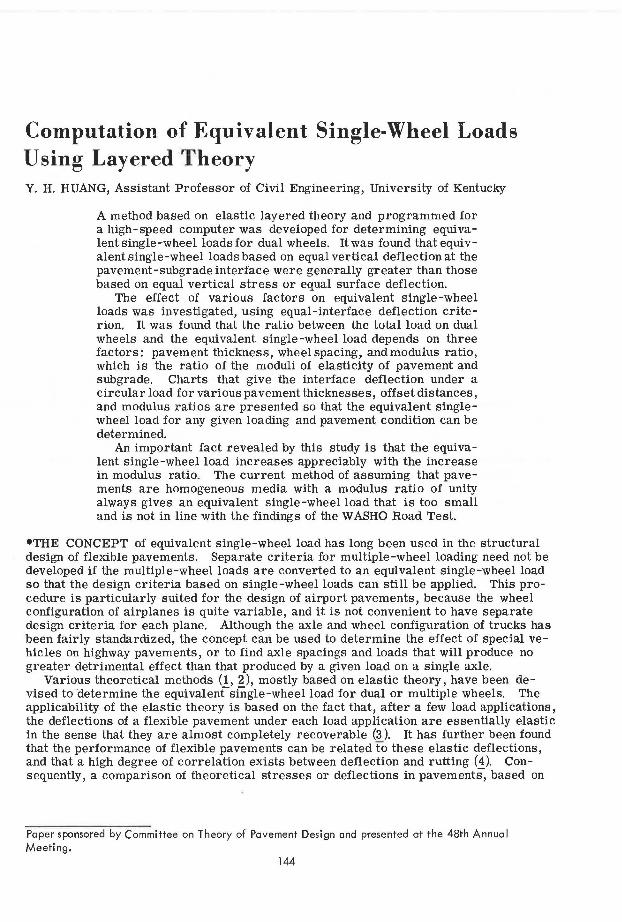
Computation of Equivalent Single-Wheel Loads Using Layered Theory Y. H. HUANG, Assistant Professor of Civil Engineering, University of Kentucky
A method based on elastic layered theory and programmed for a high-speed computer was developed for determining equivalent single-wheel loadsfor dual wheels. Itwas found that equivalent single-wheel loads based on equal vertical deflection at the pavement-subgrade interface were generally greater than those based on equal vertical stress or equal surface deflection.
The effect of various factors on equivalent single-wheel loads was investigated, using equal-interface deflection criterion. IL was found that the ratio between the total load on dual wheels and the equivalent single-wheel load depends on three factors: pavement thickness, wheelspacing, andmodulus ratio, which is the ratio of the moduli of elasticity of pavement and subgrade. Charts that give the interface deflection under a circular load for various pavement thicknesses, offset distances, and modulus ratios are presented so that the equivalent singlewheel load for any given loading and pavement condition can be determined.
An important fact revealed by this study is that the equivalent single-wheel load increases appreciably with the increase in modulus ratio. The current method of assuming that pavements are homogeneous media with a modulus ratio of unity always gives an equivalent single-wheel load that is too small and is not in line with the findings of the WASHO Road Test.
•THE CONCEPT of equivalent single-wheel load has long been used in the structural design of flexible pavements. Separate criteria for multiple-wheel loading need not be developed if the multiple-wheel loads are converted to an equivalent single-wheel load so that the design criteria based on single-wheel loads can still be applied. This procedure is particularly suited for the design of airport pavements, because the wheel configuration of airplanes is quite variable, and it is not convenient to have separate design criteria for each plane. Although the axle and wheel configuration of trucks has been fairly standardized, the concept can be used to determine the effect of special vehicles on highway pavements, or to find axle spacings and loads that will produce no greater detrimental effect than that produced by a given load on a single axle.
Various theoretical methods (1, 2 ), mostly based on elastic theory, have been devised to ·determine the equivalent single-wheel load for dual or multiple wheels. The applicability of the elastic theory is based on the fact that, after a few load applications, the deflections of a flexible pavement under each load application are essentially elastic in the sense that they are almost completely recoverable (3 ). It has further been found that the performance of flexible pavements can be related fo these elastic deflections, and that a high degree of correlation exists between deflection and rutting (4). Consequently, a comparison of theoretical stresses or deflections in pavementS, based on
Paper sponsored by Committee on Theory of Pavement Design and presented at the 48th Annual Meeting.
144

elastic theory, will give a general indication of the equivalency between single- and multiple-wheel loads as related to pavement performance.
REVIEW OF PAST WORK
145
The study of equivalent single-wheel loads was first initiated by the U. S. Corps of Engineers during World War Il, when the B-29 bombers were introduced with dualwheel assemblies. A theoretical consideration of the vertical and shear stresses in an elastic half space and an experimental measurement of the vertical deflections at the interface between pavement and subgrade were used by Boyd and Foster (5) in presenting a semirational method of determining equivalent single-wheel loads, which had been used by the Corps of Engineers to produce dual-wheel design criteria from single-wheel criteria. The method assumes that the equivalent single-wheel loadvaries with the pavement thickness. For thicknesses smaller than half the clearance between dual wheels, the equivalent single-wheel load is equal to half of the total load. However, for thicknesses greater than twice the center-to-center spacing of wheels, it is equal to the total load. By assuming a straight-line relationship between pavement thickness and wheel load on logarithmic scales, one can readily obtain the equivalent single-wheel load for any intermediate thickness. The same method has been used by the Federal Aviation Administration for the design of flexible airport pavements (1).
The application of the method and the subsequent completion of accelerated traffic tests revealed that design criteria based on the foregoing method were not very safe, and an improved method was developed by Foster and Ahlvin (2). In this method, the pavement is considered as a homogeneous, elastic, and semi-infinite half space., so that the vertical deflections at a depth equal to the thickness of pavement can be obtained from available solutions (6). A singlE?-wheel load that has the same contact radius as one of the dual wheels and results in a maximum deflection equal to that caused by the dual wheels is designated as the equivalent single-wheel load (ESWL).
In a previous paper (7 ), the author extended the work of Foster and Ahlvin by considering the pavement as a two-layer elastic system, thus taking the ratio of the moduli of elasticity of the pavement and subgrade into account. A chart was developed by which the ESWL for any combinations of pavement thickness, modulus ratio, wheel spacing, and contact radius could be obtained by a simple calculation and interpolation. It was shown that the ESWL increased appreciably with the increase in modulus ratio and that the use of layered theory would give a larger equivalent wheel load that was more in line with traffic data. However, the chart is limited because it is applicable only to dual wheels, or to multiple wheels that can be approximated by a set of duals. Furthermore, the computation was based on equal contact radius instead of equal contact pressure (i.e., the single wheel and each of the dual wheels have the same contact radius instead of the same contact pressure), although it is illustrated that the ESWL's based on equal contact radius are not too much different from those based on equal contact pressure.
The purposes in this study are (a) to develop a method for computing ESWL's based on equal contact pressure and Burmister's two-layer elastic theory (8); (b) to compare the ESWL's computed on the basis of the criteria of equal interface stress, equal surface deflection, and equal interface deflection; (c) to find the effect of various factors on ESWL's by using one of the criteria considered to have the most potential; (d) to compare the theoretical findings with traffic data to ascertain the limitations of the theory; and (e) to present a set of stress or deflection charts by which ESWL's for any given pavement thickness, modulus ratio, and axle and wheel configuration can be determined.
DESCRIPTION OF METHOD
The computation of ESWL can be based on either equal -stress or equal-deflection criteria. Assume, for example, that the maximum stress or deflection that occurs under a set of dual wheels is known. A single wheel that has the same contact pressure and results in a stress or deflection of the same amount is said to be equivalent to these duals.
146
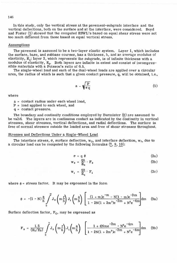
In this study, only the vertical stress at the pavement-subgrade interface and the vertical deflections, both on the surface and at the interface, were considered. Boyd and Foster (5) showed that the computed ESWL's based on equal shear stress were not too much different from those based on equal vertical stress.
Assumptions
The pavement is assumed to be a two-layer elastic system. Layer 1, which includes the surface, base, and subbase courses, has a thickness, h, and an average modulus of elasticity, E1; layer 2, which represents the subgrade, is of infinite thickness with a modulus of elasticity, E 2• Both layers are infinite in extent and consist of incompressible materials with a Poisson's ratio of 0. 5.
The single-wheel load and each of the dual-wheel loads are applied over a circular area, the radius of which is such that a given contact pressure, q, will be obtained, i.e.,
where
a_J:P l'iCL
a = contact radius under each wheel load, P = load applied to each wheel, and q = contact pressure.
(1)
The boundary and continuity conditions employed by Burmistcr (8) are assumed to be valid The layers are in continuous contact as indicated by the continuity in ve1·tical stresses, shear stresses, vertical deflections, and radial deflections. The surface is free of normal stresses outside the loaded area and free of shear stresses throughout.
Stresses and Deflections Under a Single-Wheel Load
The interface stress, a, surface deflection, w0 , and interface deflection, w1, due to a circular load can be computed by the following formulas (J.., ~' 10):
a=qB
w0 ~. F E2 o
~·F E i 2
where a = stress factor. It may be expressed in the form
(2a)
(2b)
(2c)
a = -(1 - N) ~ !"' J (m!) J (m~) [ (1 + m)e -m - N(l - m)e -3m ]dm (3a) h o h i h 1 - 2N(l + 2m2)e -2m + N2e -4,
0
Surface deflection factor, F 0 , may be expressed as
[ 1 + 4Nme -2m - N2e -4m ~dm
-2m -4m 1 - 2N(l + 2m2 )e + N2e
(3b)

Interface deflection factor, F 1 , is
where
(E / E2
) - 1
(EJ E2 ) + 1 '
E/E2 = modulus ratio ,
[
-m -3m ] (1 + m )e - N(l - m)e dm
1 - 2N(1 + 2m2)e -2m + N2e - 4m m
J 0 and J 1 = Bessel function of the first kind, order 0 and 1 respectively,
147
(3c)
r = radial distance from the center of loaded area to the point where the stress or deflection is to be sought,
a = contact radius, h = thickness of layer 1, and m = a parameter.
The infinite integrals in Eq. 3 were evaluated by a numerical method programmed for an IBM 360 computer at the University of Kentucky. Because the maximum stress or deflection due to a single -wheel load always occurs under the center of the wneel, the maximum stress or deflection can be obtained by letting r = 0 in the evaluation.
In the case of dual -wheel loads, the maximum stress or deflection can be obtained by superposition. The stress or deflection due to each wheel load was computed independently and then superposed to obtain that due to all wheels. For instance, the stress or deflection factor under a set of dual wheels at a point having a distance ri from the left wheel and rr from the r ight is the sum of two factor s, each obtained by s ubstituting r = r 1 and r = l'r respectively into Eq. 3. Because the maximum stress or deflection occw·s at some point between one wheel and the centerline of the dual , the stress or deflection at several points must be computed and the maximum value obtained. The ESWL can then be determined by a graphical method (!).
COMPARISON OF CRlTERIA
To compare the ESWL's computed on the basis of different criteria, a conventional 32,000-lb tandem-axle load was chosen. This type of loading was used in both the WASHO and the AASHO Road Tests, so the resulting information obtained from these tests can be used to compare the theoretical findings presented here.
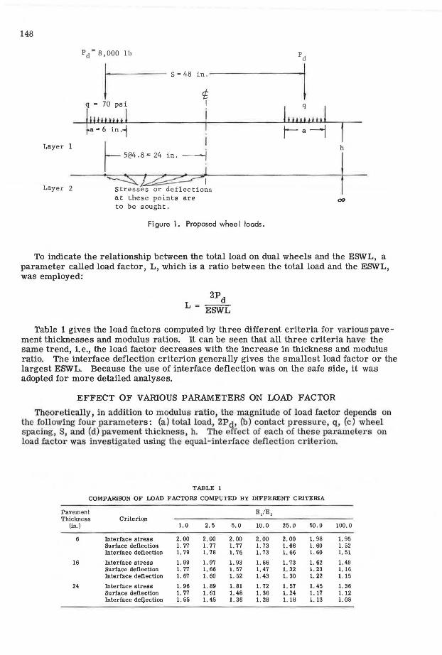
Figure 1 shows the proposed wheel loads applied to a two-layer system. The load on each axle is 16,000 lb and that on each wheel is 8,000 lb. Although the actual wheel loads are applied over dual tires , assume that they are applied on a single tire over a circular area. It can be shown that this assumption has very little effect on the ESWL, as long as the single-wheel load is also assumed to be applied on a single tire. Since the contact pressure is 70 psi, the contact radius can be determined from Eq. 1,
- f§;ff§§_ 6 . ad = f 1TX70 = m.
Under the given loads, it was found that on the surface the maximum deflection occurred under one wheel; at the interface, however, the maximum stress or deflection occurred anywhere between one wheel and the centerline of the two wheels. A computer program was developed to compute the vertical stresses and deflections at the six points shown in Figure 1 and obtain the maximum values.
148
Layer 1
Layer 2
q = 70 psi
llfW tlUl a= 6 in.1 r- [email protected] 24 '"· --!
·~~I Stresses or deflections at these points are to be sought.
Figure 1. Proposed whee I loads.
I h
I 00
To indicate the relationship between the total load on dual wheels and the ESWL, a parameter called load factor, L, which is a ratio between the total load and the ESWL, was employed:
Table 1 gives the load factors computed by three different criteria for various pavement thicknesses and modulus ratios. It can be seen that all three criteria have the same trend, i.e., the load factor decreases with the increase in thickness and modulus ratio. The interface deflection criterion generally gives the smallest load factor or the largest ESWL. Because the use of interface deflection was on the safe side, it was adopted for more detailed analyses.
EFFECT OF VARIOUS PARAMETERS ON LOAD FACTOR
Theoretically, in addition to modulus ratio, the magnitude of load factor depends on the following four parameters: (a) total load, 2Pa , (b) contact pressure, q, (c) wheel spacing, S, and (d) pavement thickness, h. Tbe effect of each of these parameters on load factor was investigated using the equal-interface deflection criterion.
TABLE 1
COMPAIUSON OF LOAD FACTORS COMPUTED BY DIFFERENT CRITERIA
Pavement E/E 2 Thickness Criteriqn
(in.) 1. 0 2.5 5. 0 10. 0 25. 0 50 . 0 100. 0
6 Interface stress 2.00 2.00 2. 00 2. 00 2. 00 l. 98 l. 95 Surface deflection 1. 77 l. 77 1. 77 1. 73 l. 66 1. 60 l. 52 Interface deflection 1. 79 l. 78 1. 76 l. 73 1. 66 1. 60 1. 51
16 Interface stress l. 99 l. 97 1. 93 l. 86 1. 73 1. 62 l. 49 Surface deflection 1. 77 l. 66 1. 57 1. 47 l. 32 1. 23 1. 16 Interface deflection 1. 67 1. 60 1. 52 l. 43 1. 30 1. 22 l. 15
24 Interface stress 1. 96 l. 89 1. 81 1. 72 l. 57 1. 45 l. 36 Surface deflection 1. 77 1. 61 1. 48 1. 36 1. 24 1. 17 l. 12 Interface deijeclion 1. 55 1. 45 1. 36 1. 28 l. 18 1. 13 l. 08
T ota l L oad (kip)
4
16
32
Contact Pressure
(psi)
40
70
110
180
1.9
TABLE 2
EFFECT OF TOTAL LOAD ON LOAD FACTOR
E / E ,
1. 0 2 . 5 5. 0 10 . 0 25. 0 50 . 0
1. 67 1. 63 1. 54 1. 45 1. 33 1. 22
1. 67 1. 62 1. 54 1. 45 1. 32 1. 22
1. 67 1. 60 1. 52 1. 43 1. 30 1. 22
1. 63 1. 57 1. 50 1. 40 1. 28 1. 20
TABLE 3
EFFECT OF CONTACT PRESSURE ON LOAD FACTOR
1. 0
1. 64
1. 67
1. 67
1. 70
E / E ,
2.5 5. 0 10. 0 25. 0
1. 57 1. 51 1. 41 1. 29
1. 60 1. 52 1. 43 1. 30
1. 61 1. 54 1. 44 1. 31
1. 63 1. 56 1. 45 1. 33
TOTAL LOAD • 16, 000 lb CONTACT PRESSURE • 70 psi PAVEMENT THICJi:NESS • 16 in.
50. 0
1. 21
1. 22
1. 22
1. 23
100 . 0
1. 16
1. 15
1. 15
1. 14
100.0
1. 14
1. 15
1. 15
1. 17
l.o'--~-'-..o.c:::.--1.~~.L-~....1.-~-1.~~.L-~-1-~--1.~~..._~~
0 10 20 30 40 50 60 70 80 90 100
WHEEL SPACING (in,)
Figure 2. Effect of wheel spacing on load factor.
149
150
1. 7
1. 5
1.4
1.3
1. 2
1.1
1.0 0
Effect of Total Load
10 20 30 40
TOTAL LOAD • 16,000 lb CONTACT PRESSURE • 70 psi WHEEL SPACING • 48 in.
so 60 70 80 90
PAVEMENT THICKNESS (in.)
Figure 3. Effect of pavement thickness on load factor.
100
Table 2 gives the effect of total load on load factor. The computation was based on average conditions with q = 70 psi, S = 48 in., and h = 16 in. The load factor decreases slightly with the increase in total load. An eight-fold increase in total load only causes a decrease in load factor by not more than 0. 06. This is the reason the load factor, in -stead of the ESWL, was used because the load factor is practically independent of the total load, whereas the ESWL changes with the total load.
Effect of Contact Pressure
Table 3 gives the effect of contact pressure on load factor. The computation was based on Pa= 8,000 lb, S = 48 in., and h = 16 in. The load factor increases slightly with the increase in contact pressure. However, under the given pavement and loading conditions, the effect of contact pressure is not significant.
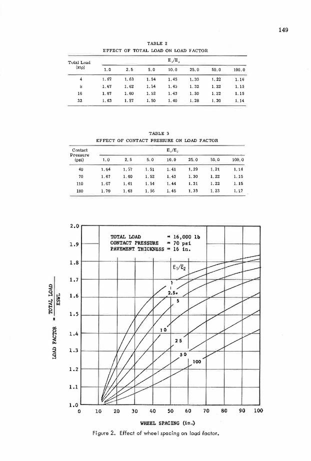
Effect of Wheel Spacing
Figure 2 shows that wheel spacing has a tremendous effect on load factor. The larger the wheel spacing, the greater the load factor. For smaller modulus ratios, the effect of wheel spacing is more conspicuous at smaller spacings as indicated by a rapid change in the slope of the curves. For larger modulus ratios, the effect is more conspicuous at larger spacings because of the superior load-distributing characteristics of the pavement.
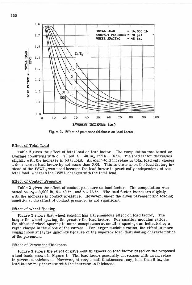
Effect of Pavement Thickness
Figure 3 shows the effect of pavement thickness on load factor based on the proposed wheel loads shown in Figure 1. The load factor generally decreases with an increase in pavement thickness. However, at very small thicknesses, say, less than 6 in., the load factor may increase with the increase in thickness.
151
COMPARISON WITH ROAD TESTS
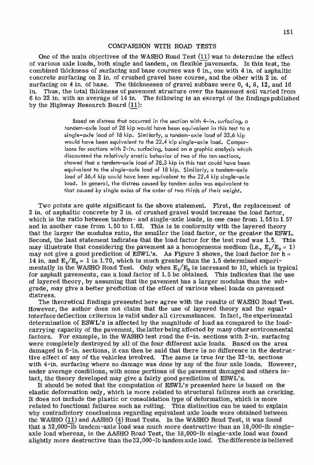
One of the main objectives of the WASHO Road Test (11) was to determine the effect of various axle loads, both single and tandem, on flexiblepavements. In this test, the combined thickness of surfacing and base coutses was 6 in., one with 4 in. of asphaltic concrete surfacing on 2 in. of crushed gravel base course, and the other with 2 in. of surfacing on 4 in. of base. The thicknesses of gravel subbase were O, 4, 8, 12, and 16 in. Thus, the total thickness of pavement structure over the basement soil varied from 6 to 22 in. with an average of 14 in. The following is an excerpt of the findings published by the Highway Research Board (!_!):
Based on distress that occurred in the section with 4-in. surfacing, a tandem-axle load of 28 kip would have been equivalent in this test to a single-axle load of 18 kip. Similarly, a tandem-axle load of 33.6 kip would have been equivalent to the 22.4 kip single-axle load. Comparisons for sections with 2-in. surfacing, based on a graphic analysis which discounted the relatively erratic behavior of two of the ten sections, showed that a tandem-axle load of 28.3 kip in this test could have been equivalent to the single-axle load of 18 kip. Similarly, a tandem-axle load of 36.4 kip could have been equivalent to the 22.4 kip single-axle load. In general, the distress caused by tandem axles was equivalent to that caused by single axles of the order of two thirds of their weight.
Two points are quite significant in the above statement. First, the replacement of 2 in. of asphaltic concrete by 2 in. of crushed gravel would increase the load factor, which is the ratio between tandem - and single-axle loads, in one case from 1. 55 to 1. 57 and in another case from 1. 50 to 1. 62. Thi1s is in conformity with the layered theory that the larger the modulus ratio, the smaller the load factor, or the greater the ESWL. Second, the last statement indicates that the load factor for the test road was 1. 5. This may illustrate that considering the pavement as a homogeneous medium (i.e., E1/E2 = 1) may not give a good prediction of ESWL's. As Figure 3 shows, the load factor for h = 14 in. and E/E2 = 1 is 1. 70, which is much greater than U1e 1. 5 determined experimentally in the WASHO Road Test. Only when E/E2 is increased to 10, which is typical for asphalt pavements, can a load factor of 1. 5 be obtained This indicates that the use of layered theory, by assuming that the pavement has a larger modulus than the subgrade, may give a better prediction of the effect of various wheel loads on pavement distress.
The theoretical findings presented here agree with the results of WASHO Road Test. However, the author does not claim that the use of layered theory and the equalinterface deflection criterion is valid under all circumstances. In fact, the experimental determination of ESWL's is affected by the magnitude of load as compared to the loadcarrying capacity of the pavement, the latter being affected by many other environmental factors. For example, in Ute WASHO test road the 6-in. sections with 2-in. surfacing were completely destroyed by all of the four different axle loads. Based on the area damaged in 6-in. sections, it can then be said that there is no difference in the destructive effect of any of the vehicles involved. The same is true for the 22-in. sections with 4-in. surfacing where no damage was done by any of the four axle loads. However, under average conditions, with some portions of fue pavement damaged and others intact, the theory developed may give a fairly good prediction of ESWL's.
It should be noted that the computation of ESWL's presented here is based on the elastic deformation only, which is more related to structural failures such as cracking. It does not include the plastic or consolidation type of deformation, which is more related to functional failures such as rutting. This distinction can be used to explain why contradictory conclusions regarding equivalent axle loads were obtained between the WASHO (11) and AASHO (4) Road Tests. In the WASHO Road Test, it was found that a 32,000-lb tandem-axle load was much more destructive than an 18,000-lb singleaxle load whereas, in the AASHO Road Test, the 18,000-lb single-axle load was found slightly more destructive Utan the 3 2, 000-lb tandem axle load. The difference is believed
152
to be caused by the use of pavement serviceability index in the AASHO Road Test fo1· the determination of equivalent wheel loads. In addition to cracking and patching, this index is based on slope variance and rut depth, which were not considered in the WASHO Road Test. Because the ESWL based on layered theory is greater than that obtained from the AASHO Road Test, the use of layered theory is on the safe side.
The suggestion of using layered theory to compute ESWL's should not imply that the equivalencies obtained from the AASHO Road Test are no longer valid. In fact, if a pavement is overdesigned and its serviceability is of major concern, the equivalent loads as determined from the AASHO Road Test are quite adequate and should be used. On the other hand, if the pavement is underdesigned and the prevention of failures is a majol' factor, as is in the case of military or airport construction, the use of Bw·mister' s two-layer theory, instead of Boussinesq's single-layer theory, is suggested.
CONCLUSIONS
In this study, a method was developed for computing equivalent single-wheel loads for dual wheels. The method is based on Burmister's two-layer elastic theory and assumes that both single and dual wheels have the same contact pressure. Three criteria-equal interface stress, equal surface deflection, and t!qual interface deflec tion-were investigated. It was found that, for a conventional 32,000-lb tandem-axle load, the equivalent single-axle loads determined by the equal-interface deflection criterion were generally the largest, whereas those determined by the equal-interface stress were the smallest. Because the use of the equal-interface deflection criterion was on the safe side, it was adopted for more detailed analyses.
To indicate the relationship between the total load on dual wheels and the ESWL, a parameter called load factor, which is a ratio of the total load and the ESWL, was em -ployed. It was found that total load and contact pressure had a relatively small effect on load factor. However, the load factor decreases, or the ESWL increases appreciably, with an increase in pavement thickness and modulus ratio, or with a decrease in wheel spacing.
An important fact revealed by this study is that the ESWL increases appreciably with an increase in modulus ratio, E/E2• The current method of considering pavements as homogeneous media (i.e., E/E2 = 1) always gives an ESWL that is too small and is not in line with the findings of the WASHO Road Test.
ACKNOWLEDGMENTS
The study reported herein was part of a faculty research program sponsored by the Department of Civil Engineering, University of Kentucky. The support given by the University of Kentucky Computing Center through the use of the IBM 360 computer and related technical service is appreciated.
REFERENCES
1. Yoder, E. J. Principles of Pavement Design. John Wiley and Sons, pp. 41-48, 358, and 341, 1959.
2. Foster, C. R., and Ahlvin, R. G. Development of Multiple-Wheel CBR Design Criteria. Jour. Soil Mech. and Found. Div., ASCE, pp. 1647-12, May 1958.
3. Wbiffin, A. C., and Lister, N. W. The Application of Elastic Theory to Flexible Pavements. Proc. Internat. Conf. on Structural Design of Asphalt Pavements, Univ. of Michigan, pp. 499-521, 1962.
4. The AASHO Road Test: Report 5-Pavement Research. Highway Research Board Spec. Rept. 61E, p. 137, 1962.
5. Boyd, W. K, and Foster, C. R. Design Curves for Very Heavy Multiple-Wheel Assemblies. In Development of CBR Flexible Pavement Design Method for Airfields-A Symposium. Trans. ASCE, Vol. 115, pp. 534-546, 1950.
6. Foster, C. R., and Ahlvin, R. G. Stresses and Deflections Induced by a Uniform Circular Load. HRB Proc., Vol. 33, pp. 467-470, 1954.
153
7. Huang, Y. H. Chart for Determining Equivalent Single-Wheel Loads. Jour. Highway Div., ASCE, pp. 115-128, Nov. 1968.
8. Burmister, D. M. The Theory of Stresses and Displacements in Layered Systems and Applications to the Design of Airports Runways. HRB Proc., Vol. 23, pp. 126-144, 1943.
9. Fox, L. Computation of Traffic Stresses in a Simple Road Structure. Road Research Tech. Paper No. 9, HMSO, London, 1948.
10. Huang, Y. H. Stresses and Displacements in Viscoelastic Layered Systems Under Circular Loaded Areas. PhD dissertation, Univ. of Virginia, 1966.
11. The WASHO Road Test: Part 2-lfest Data, Analyses , Findings. HRB Spec. Rept. 22, 1955.
Appendix
DEFLECTION CHARTS
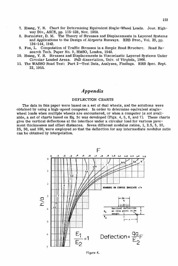
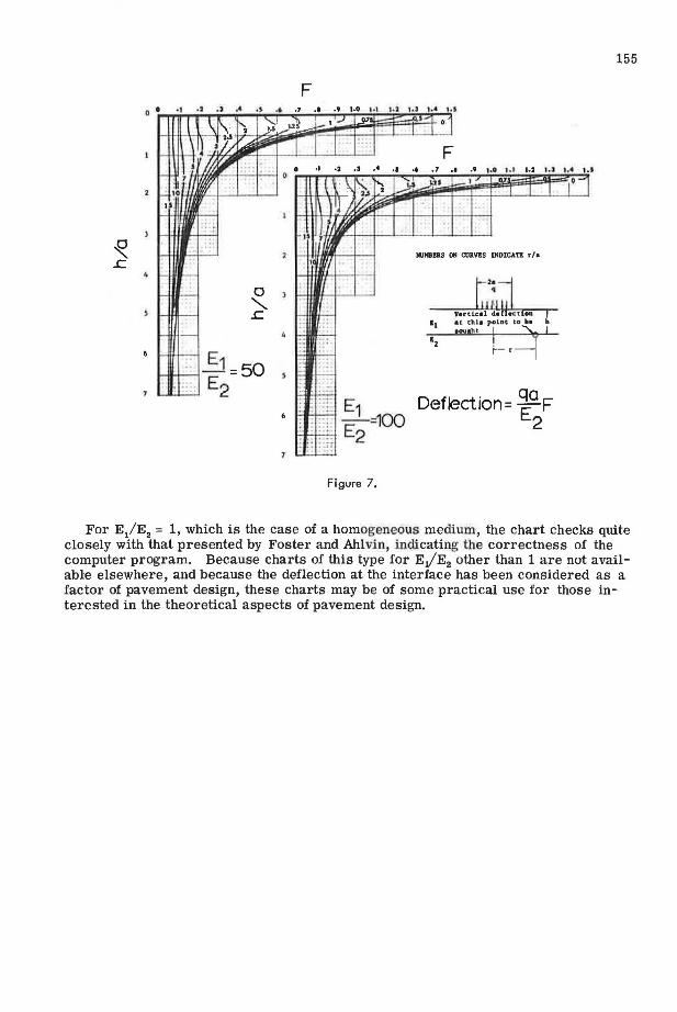
The data in this paper were based on a set of dual wheels, and the solutions were obtained by using a high-speed computer. In order to determine equivalent singlewheel loads when multiple wheels are encountered, or when a computer is not available, a set of charts based on Eq. 3c was developed (Figs. 4, 5, 6, and 7 ). These charts give the vertical deflections at the interface under a circular load for various pavement thicknesses and offset distances. Seven different modulus ratios, 1, 2. 5, 5, 10, 25, 50, and 100, were employed so that the deflection for any intermediate modulus ratio can be obtained by interpolation.
F 0 •l .2 ,3 .4 .s .6 o7 .1 o9 1.0 1·1 1•2 lol 1.4 l•S
0
\ \ lJ v o.s"' /
' i,0.7l 0 ,....
l I
/ . t:::::: ) s v/ [....-"" .........-:'.
2 1.5 V;, ~ ~:::?: .. I 2.5
I· ..,,... .... I VA ~ [?.' .
· ~
4 /J t';f.j ff'' I ·.~ llUMB!RS ON CURVES IllDICATE r /a - s
: f~ ti! : : >- 7
1- 101 h w. .. t12;1j j ....
' ''!/). .. i s . :A : ..
Ve r tleal d~fl eot loa ~ 'I , . ....
at thia point c.o be .. £1 ... oought ! ~ I ....
. . J : .. .. . 12 . ... I' ,, ... .. ..
:
E1 Deflection= qaF - =1 E2 E2
Figure 4.

154
F
. E1 -: -E =2.5
~ ... ~._,__.· 2
0 ..........
E s:; - 1 =10 E2
F
_,_ Figure 5.
25
Figure 6.
F
Deflection= ~a F 2
NUHBUS Otl CURVES lllDlCATI r/a
Deflection= ~a F 2
a
"" ..c
F
Figure 7.
,.2 1.J ,... '·"
F •• .1 .• ·' ,.o •.• 1.2 '·' ••• ..,
NUHB!RS OH CURVIS IHDICATB r/a
Yertiul dd •ct oa at thh point ta ba h
1ou1ht ! ~ I r-- •
Deflection= ~a F 2
155
For E/E2 = 1, which is the case of a homogeneous medium, the chart checks quite closely with that presented by Foster and Ahlvin, indicating the correctness of the computer program. Because charts of this type for EJE2 other than 1 are not available elsewhere, and because the deflection at the interface has been considered as a factor of pavement design, these charts may be of some practical use for those interested in the theoretical aspects of pavement design.