Embed Size (px)
Citation preview
173
4
Deploying IS-IS Networks
Now that you understand the IS-IS routing protocol and are
familiar with the concepts of multi-area routing and routing
domains, you are ready to deploy IS-IS on a network. This
chapter provides information about deploying IS-IS within a
network, and answers questions such as Where do you place
routing domain boundaries? Why? And how do you deal with
IP route summarization?
Domains and Hierarchical Network Design
One for the first questions you need to ask is “Where should I
put the L1/L2 borders in a network?” In other words, how do
IS-IS domains overlay onto a network’s hierarchical structure?
Of course, before answering this question, we need to ask yet
another—what sort of hierarchy is the network built on? Figure
4-1 illustrates the two most common types.
Traditionally, hierarchical network designs have three layers of
intermediate systems: the core, distribution, and access layers.
Each of these layers serves a specific purpose in the network,
splitting network design into three smaller problems.
•
The network
core layer
is tasked with forwarding
packets between the different sections of the network as
quickly as possible. Core intermediate systems are
5288_ch04 Page 173 Tuesday, September 10, 2002 4:01 PM

174
Chapter 4 Deploying IS-IS Networks
normally connected through a full-mesh, partial-mesh,
or some sort of ring topology to other core intermediate
systems throughout the network.
•
The intermediate systems within the
distribution layer
act as a place to aggregate traffic and to summarize
routes between the access and core layers of
intermediate systems.
•
The
access layer
is where customers (or end users)
actually connect to the network.
Many very large networks are built using this three-level hierar-
chy, since it tends to scale well and is well understood. There is
another model used in situations where latency through interme-
diate systems must be reduced (generally by using fast intermedi-
ate systems and by reducing the actual number of intermediate
systems a packet must pass through to make it through the net-
work), or in smaller networks. This alternate approach is the two-
tier model, which is also illustrated in Figure 4-1.
•
The core serves the same purpose in a two-layer design
as it does in a three-layer design—it forwards packets
Core
Three-Level Hierarchy
Two-Level Hierarchy
DistributionCore
Aggregation
Access
Fig 04 01
Figure 4–1 Two models of hierarchical networks
5288_ch04 Page 174 Tuesday, September 10, 2002 4:01 PM

Domains and Hierarchical Network Design
175
between the different sections of the network as quickly
as possible (or gets the packets routed to a peer network
as quickly as possible).
•
The
aggregation layer
serves as a combined distribution
and access layer: It sets policies for traffic entering the
network, offers a summarization point for reachable
destinations within the aggregation layer, and provides
traffic aggregation.
With these two models of network hierarchy in mind, let’s
examine several different options for laying out domains within
a network.
Putting the Network in One Routing Domain
One of the most common ways to design a large-scale IS-IS net-
work is to place all the intermediate systems in one domain.
Although this approach might not seem optimal at first glance,
the following list includes some of the many reasons to design
an IS-IS network this way.
•
Configuring the intermediate systems in a single domain
network is much simpler. All area addresses remain the
same, and there is no need to consider which interfaces
are in which level or domain.
•
Designing a single domain network is much simpler.
The network designer doesn’t need to consider where IP
address summarization will take place, for instance, or
where domain borders should be.
•
The network designer does not need to consider next
hop reachability for BGP, tunnels, or any other
applications. Since all the endpoints are in the same
domain, and all the intermediate systems within a
domain share the same topology databases and
5288_ch04 Page 175 Tuesday, September 10, 2002 4:01 PM

176
Chapter 4 Deploying IS-IS Networks
reachability information, there is no need to deploy
route leaking or any other mechanism to ensure the
next hops are always reachable.
In fact, most of the currently deployed large-scale IS-IS net-
works have been designed and configured as a single large level
1 or level 2 domain and have up to 1,000 intermediate systems.
Single domain networks have some disadvantages as well.
•
A flooding storm or other IS-IS problem can bring down
the entire network, not just some small part of it.
•
There is no border on which to summarize IP prefixes or
otherwise hide information; all LSPs must be flooded
throughout the network.
Before we go on, it is important to note that most of the existing
IS-IS networks were built and deployed by service providers
many years before the idea of route leaking was implemented.
This is relevant because the network designers could only build
a single domain network if they wanted to maintain reachability
and optimal routing for destinations learned through BGP. In
other words, a single domain was the only real option at the
time. By taking advantage of the route leaking enhancement,
many networks are now able to enjoy the benefits of separating
the network into multiple domains.
If you do put all the intermediate systems in a single domain,
what type of domain should it be? The network can be config-
ured as a single level 1 routing domain, a single level 2 routing
domain, or a single overlaid level 1/level 2 routing domain.
Configuring all the intermediate systems within a network to
run both level 1 and level 2 routing causes all reachability and
topology information to be flooded throughout the network
twice—once as level 1 routing and topology information, and
5288_ch04 Page 176 Tuesday, September 10, 2002 4:01 PM

Domains and Hierarchical Network Design
177
once as level 2 routing and topology information. This result
does not improve scalability, so we do not suggest running an
overlaid level 1/level 2 routing domain.
It’s also possible to configure all the intermediate systems in the
same domain as level 1–only intermediate systems, so the
entire network appears to be a single level 1 routing domain. All
the reachability and topology information would be flooded
once, as level 1 reachability information, rather than being
flooded twice. This is the traditional way large-scale IS-IS net-
works were initially configured. The only problem with config-
uring all the intermediate systems as level 1–only intermediate
systems is that if you ever decide to move to a two-level hierar-
chy, it can be difficult to move from a single level 1 domain to a
level 1/level 2 design with a level 2 domain and level 1 domains
connected to it.
Finally, you can configure all the intermediate systems to be
within the level 2 routing domain—while all the intermediate
systems would be in the same domain, they would be config-
ured for only level 2 routing. Adding a second level of hierarchy
would be easy with this sort of a design; since the level 2
domain is already contiguous, you can just add level 1 domains
off the network or reassign nodes to them. The main problem
with configuring a large network as a single level 2 domain is
providing reachability to CLNS end systems. If there are any
CLNS end systems within the network, there won’t be a level 1
domain for them to reside in, so static CLNS routes will need to
be configured to provide reachability to them.
The Pure Level 2 Core
If you have decided you don’t want to place all the intermedi-
ate systems in your network into a single routing domain, then
5288_ch04 Page 177 Tuesday, September 10, 2002 4:01 PM
178
Chapter 4 Deploying IS-IS Networks
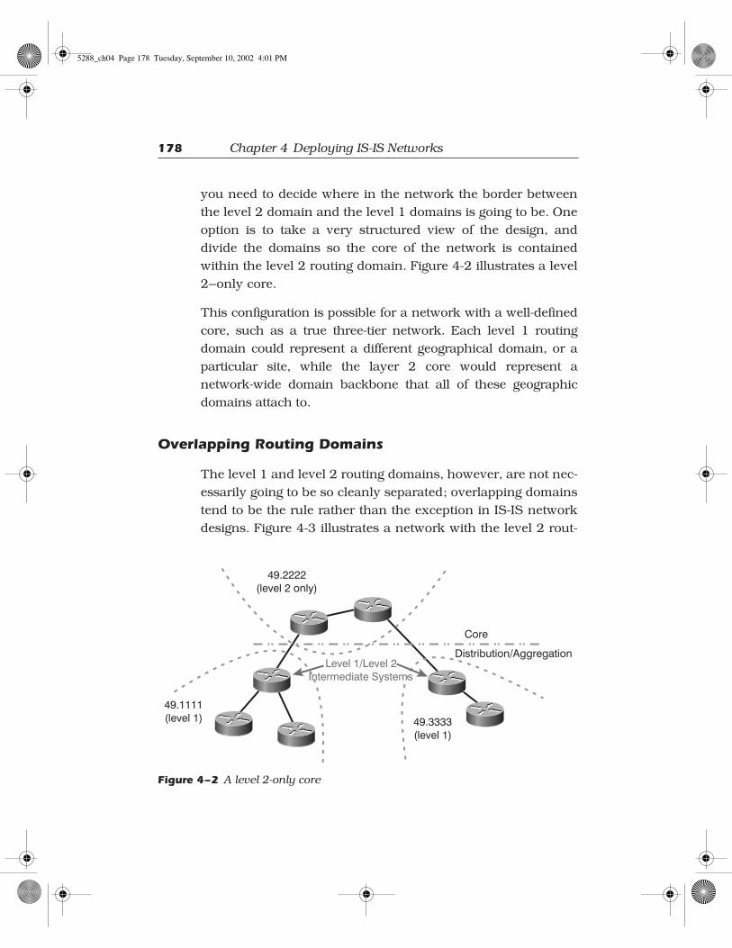
you need to decide where in the network the border between
the level 2 domain and the level 1 domains is going to be. One
option is to take a very structured view of the design, and
divide the domains so the core of the network is contained
within the level 2 routing domain. Figure 4-2 illustrates a level
2–only core.
This configuration is possible for a network with a well-defined
core, such as a true three-tier network. Each level 1 routing
domain could represent a different geographical domain, or a
particular site, while the layer 2 core would represent a
network-wide domain backbone that all of these geographic
domains attach to.
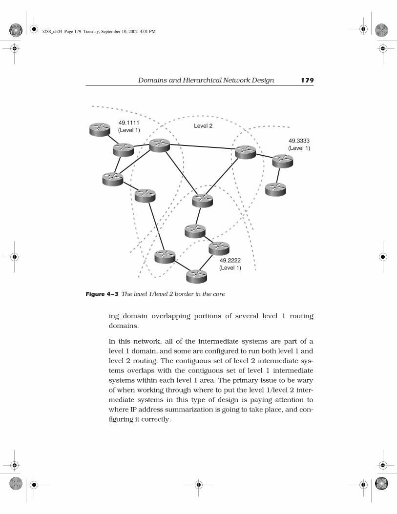
Overlapping Routing Domains
The level 1 and level 2 routing domains, however, are not nec-
essarily going to be so cleanly separated; overlapping domains
tend to be the rule rather than the exception in IS-IS network
designs. Figure 4-3 illustrates a network with the level 2 rout-
Core
Distribution/Aggregation
49.1111(level 1) 49.3333
(level 1)
Level 1/Level 2Intermediate Systems
49.2222(level 2 only)
Figure 4–2 A level 2-only core
5288_ch04 Page 178 Tuesday, September 10, 2002 4:01 PM
Domains and Hierarchical Network Design
179
ing domain overlapping portions of several level 1 routing
domains.
In this network, all of the intermediate systems are part of a
level 1 domain, and some are configured to run both level 1 and
level 2 routing. The contiguous set of level 2 intermediate sys-
tems overlaps with the contiguous set of level 1 intermediate
systems within each level 1 area. The primary issue to be wary
of when working through where to put the level 1/level 2 inter-
mediate systems in this type of design is paying attention to
where IP address summarization is going to take place, and con-
figuring it correctly.
49.1111(Level 1)
49.2222(Level 1)
49.3333(Level 1)
Level 2
Figure 4–3 The level 1/level 2 border in the core
5288_ch04 Page 179 Tuesday, September 10, 2002 4:01 PM

180
Chapter 4 Deploying IS-IS Networks
Domain Border Considerations
When deciding where to place the level 1/level 2 border, you
need to consider the following factors.
•
The physical topology of the network. If there is a
natural place in which to create a pure level 2 routing
domain, then you should probably consider creating
one.
•
Domain partitions. Consider the result of single- and
double-link failures. If a single-link failure would cause
a level 2 partition, you should carefully consider how
to either increase or decrease the size of the level 2
routing domain to avoid this possibility.
•
Domain sizes and flooding diameters. In Chapter 3 we
noted that the primary reason for breaking a network
up into smaller domains is to reduce the amount of
information any given intermediate system must
handle when a network topology change occurs, which
also results in a reduction of the flooding scope. If your
network has a number of large level 1 routing domains,
and a “no intermediate system” level 2 routing domain
(in other words, no L2-only nodes exist), it might be
worth considering changing the location of the level 1/
level 2 border to balance the flooding domains.
•
IP address summarization. You should consider the IP
addressing within the network, and where it can be
best summarized. You can only summarize IP
addresses at domain borders.
•
Traffic flow. You should consider the paths that traffic
will normally take through the network, and how
domain borders will affect that traffic flow. For
5288_ch04 Page 180 Tuesday, September 10, 2002 4:01 PM

Other Design and Deployment Issues
181
instance, if there is a large data center that most traffic
will flow to and from, it might make sense to place this
data center entirely in the level 2 routing domain.
Other Design and Deployment Issues
Beyond deciding whether or not to divide an IS-IS network into
multiple domains, and where the domain borders should be if
you decide to separate the domain, what other issues should
you look for when designing and deploying an IS-IS network?
There are a few things that you should look at regardless of
what routing protocol you are using, such as summarizing IP
prefixes or dialer interfaces, while there are others, which are
more specific to IS-IS, such as tuning the various IS-IS timers.
Summarizing IP Prefixes
One of the most important issues to address when designing or
deploying an IP network is prefix summarization. Summariza-
tion is a very simple concept—the basic premise is to reduce the
amount of information that intermediate systems must handle
while computing the best paths through the network by hiding
information about reachable destinations. For instance, in the
network illustrated in Figure 4-4, each time intermediate sys-
tems B and C need to run SPF, they have to compute the best
path to all 16 of the networks illustrated, even though they are
all reachable only through Router A.
Since all of these networks are reachable through a single point,
why not describe them with a single prefix (or advertisement),
rather than 16? That is exactly what summarization does—rather
than advertise a large number of destinations, they are summa-
rized into a single prefix at intermediate system A, which then
5288_ch04 Page 181 Tuesday, September 10, 2002 4:01 PM

182
Chapter 4 Deploying IS-IS Networks
advertises it towards B and C. In this case, 10.1.0.0/21 would
include all of the destinations from 10.1.0.0 through 10.1.15.255.
Calculating IP Summaries
IP summarization, although simple in principle, is a con-
fusing topic to many people. The general idea is to
shorten the prefix length (the number of bits set in the
subnet mask) so a single advertisement covers, or repre-
sents, more address space. For instance, in the network
illustrated in Figure 4-4, we begin with 16 different desti-
nations, each with a 24-bit mask.
A
B
C
10.1
.0.0
/24
10.1
.1.0
/24
10.1
.2.0
/24
10.1
.3.0
/24
10.1
.4.0
/24
10.1
.5.0
/24
10.1
.6.0
/24
10.1
.7.0
/24
10.1
.8.0
/24
10.1
.9.0
/24
10.1
.10.
0/24
10.1
.11.
0/24
10.1
.12.
0/24
10.1
.13.
0/24
10.1
.14.
0/24
10.1
.15.
0/24
All intermediate systems are L2
Figure 4–4 A highly summarizable address space
5288_ch04 Page 182 Tuesday, September 10, 2002 4:01 PM
Other Design and Deployment Issues
183
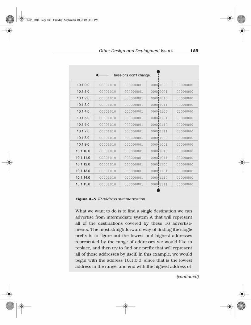
Figure 4–5
IP address summarization
What we want to do is to find a single destination we can
advertise from intermediate system A that will represent
all of the destinations covered by these 16 advertise-
ments. The most straightforward way of finding the single
prefix is to figure out the lowest and highest addresses
represented by the range of addresses we would like to
replace, and then try to find one prefix that will represent
all of those addresses by itself. In this example, we would
begin with the address 10.1.0.0, since that is the lowest
address in the range, and end with the highest address of
00001010
00001010
00001010
00001010
00001010
00001010
00001010
00001010
00001010
00001010
00001010
00001010
00001010
00001010
00001010
00001010
10.1.0.0
10.1.1.0
10.1.2.0
10.1.6.0
10.1.12.0
10.1.4.0
10.1.10.0
10.1.8.0
10.1.14.0
10.1.3.0
10.1.7.0
10.1.13.0
10.1.5.0
10.1.11.0
10.1.9.0
10.1.15.0
000000001
000000001
000000001
000000001
000000001
000000001
000000001
000000001
000000001
000000001
000000001
000000001
000000001
000000001
000000001
000000001
00000000
00000001
00000010
00000110
00001100
00000100
00001010
00001000
00001110
00000011
00000111
00001101
00000101
00001011
00001001
00001111
00000000
00000000
00000000
00000000
00000000
00000000
00000000
00000000
00000000
00000000
00000000
00000000
00000000
00000000
00000000
00000000
These bits don’t change.
(continued)
5288_ch04 Page 183 Tuesday, September 10, 2002 4:01 PM

184
Chapter 4 Deploying IS-IS Networks
Summarization in IS-IS can only be configured at the intermedi-
ate system that is injecting the IP destinations or at a domain
border. For instance, in Figure 4-4, the specific routes are static
routes in intermediate system A, so it is the only node that
could summarize the routes into a single advertisement. To con-
figure a summary on a Cisco router in IS-IS, use the
summary-
address
command within the
router isis
submode.
!router isis summary-address 10.1.0.0 255.255.240.0 redistribute static metric 10 level-2 net 49.0001.1111.1111.1111.00!
Once these commands are configured on A, its routing table will
show the 16 individual 24-bit prefixes plus the single 21-bit
summary prefix.
router-a#show ip route.... 10.0.0.0/8 is variably subnetted, 16 subnets, 2 masksS 10.1.11.0/24 [115/10] via 10.1.11.1, Serial11S 10.1.10.0/24 [115/10] via 10.1.10.1, Serial10S 10.1.9.0/24 [115/10] via 10.1.9.1, Serial9
10.1.15.255. Is there any prefix we can use to represent
this entire address range? If we were to lay all of these
addresses out in binary, we would find that the top 20
bits of every address remain the same throughout the
entire address range.
So, we can use a single prefix with 20 bits set in its sub-
net mask to represent all of the addresses covered by the
16 individual prefixes, each with 24 bits set in their sub-
net masks. This 20-bit prefix is called a
summary
.
5288_ch04 Page 184 Tuesday, September 10, 2002 4:01 PM

Other Design and Deployment Issues
185
S 10.1.8.0/24 [115/10] via 10.1.8.1, Serial8S 10.1.14.0/24 [115/10] via 10.1.14.1, Serial14S 10.1.13.0/24 [115/10] via 10.1.13.1, Serial13S 10.1.12.0/24 [115/10] via 10.1.12.1, Serial12S 10.1.3.0/24 [115/10] via 10.1.3.1, Serial3S 10.1.2.0/24 [115/10] via 10.1.2.1, Serial2S 10.1.1.0/24 [115/10] via 10.1.1.1, Serial1iiii ssssuuuu 11110000....1111....0000....0000////22220000 [[[[111111115555////0000]]]] vvvviiiiaaaa 0000....0000....0000....0000,,,, NNNNuuuullllllll0000S 10.1.0.0/24 [115/10] via 10.1.10.1, Serial0S 10.1.7.0/24 [115/10] via 10.1.7.1, Serial7S 10.1.6.0/24 [115/10] via 10.1.6.1, Serial6S 10.1.5.0/24 [115/10] via 10.1.5.1, Serial5S 10.1.4.0/24 [115/10] via 10.1.4.1, Serial4
Note the summary route indicated in bold type in the output
above; IS-IS automatically injects the route into the routing
table when the summary is configured on A. On intermediate
system B, issuing the
show ip route
command shows only the
summary route; none of the components are shown.
router-b#show ip route.... 10.0.0.0/20 is subnetted, 1 subnetsi L2 10.1.0.0 [115/20] via 208.0.2.5, Serial0/3
The summary route A is advertising to intermediate system B
looks like any other L2 route B is receiving.
IP Summaries and Routing Black Holes
One issue to be careful of when summarizing destinations in a
network with redundant level 1 and level 2 connections is rout-
ing black holes. Figure 4-6 illustrates a situation where a routing
black hole can occur.
This network design appears to be perfectly reasonable when it’s
initially deployed, with redundancy provided for destinations
within the 192.168.50.0/24 network. However, when the link
5288_ch04 Page 185 Tuesday, September 10, 2002 4:01 PM

186
Chapter 4 Deploying IS-IS Networks
between B and D fails, the network administrators suddenly dis-
cover that 192.168.50.0/24 is no longer reachable. Why? Since
both intermediate systems B and C are advertising the same
route to A, A must choose between the two routes when calculat-
ing the best paths through the network. In this case, we will
assume A chooses the path through the level 1/level 2 border B
for all traffic destined to 192.168.48.0/20, which includes all
the destinations on the 192.168.50.0/24 network. When the
link between intermediate systems B and D fails, there is no
reason for B to stop advertising the 192.169.48.0/20 IP sum-
mary, since it still has at least one component in the summary,
192.168.49.0/24, which is directly attached. In fact, neither B
nor C will advertise any changes in this summary at all.
Router A will continue routing all traffic for any destination
within 192.168.48.0/20 through intermediate system B, and B
B
C
D
A
192.168.50.0/24
192.168.49.0/24
192.168.48.0/20
49.1111
(Level 1)
49.2222
(Level 2)
192.168.48.0/20
Figure 4–6 A routing black hole in the making
5288_ch04 Page 186 Tuesday, September 10, 2002 4:01 PM

Other Design and Deployment Issues
187
will drop the traffic destined to 192.168.50.0/24, since it no
longer has a route to that destination network. This result is a
very common problem in network designs with redundant con-
nections between L1 and L2 domains.
How can you resolve this problem? One option is to simply not
have redundant paths between L1 and L2 domains. This is not
a very good solution, because it results in single points of fail-
ure. Another option is to simply not summarize between L1 and
L2. Again, this is not a very good option either, since it will
likely limit the scaling of your network over the long haul.
Yet another option is to provide an alternate link between the
redundant connecting intermediate systems between the
domains, as illustrated in Figure 4-7.
B
C
D
A
192.168.50.0/24
192.168.49.0/24
192.168.48.0/20
49.1111
(Level 1)
49.2222
(Level 2)
192.168.48.0/20
Figure 4–7 Resolving the routing black hole
5288_ch04 Page 187 Tuesday, September 10, 2002 4:01 PM

188
Chapter 4 Deploying IS-IS Networks
This solution provides intermediate system B with an alternate
link to reach the 192.168.50.0/24 network should the link
between B and D fail. Links of this type must be used with some
caution, however, and their capacity must be carefully planned.
Assuming that the link between B and C will only carry one
remote site’s worth of traffic probably is not a good idea. If there
are, say, 200 remote sites dual-homed between Routers B and C,
a single massive failure could redirect all of the traffic to and from
these sites across this single link. Careful network traffic flow and
capacity planning are required to make this solution work well.
Some IS-IS implementations offer still another solution: auto-
matic deaggregation. The details of the operation might be
rather involved in some cases. Both intermediate systems B and
C are part of the same level 1 and level 2 domains. Before any
failure, intermediate system B might notice that another node (C
in this example) is advertising the same summary through the
level 2 domain. At the same time, intermediate system B can
verify that C is reachable through the level 1 domain when it
runs SPF for the domain and C’s LSP is part of the resulting
tree. If the second condition changes (C is not reachable any-
more through the level 1 domain), but the first one is main-
tained, then B can deaggregate the summary and advertise the
more specific routes. Of course, C would follow a similar pro-
cess and it would also advertise the specific routes it can reach.
The result is that intermediate system A (and all the other nodes
in the level 2 domain) now have specific knowledge of which
prefixes are reachable through which entry into the level 1
domain. Once the partition is resolved, both intermediate sys-
tems will continue advertising just the summary.
Timer Tuning
Within the IS-IS protocol, there are many timers which may be
configured or set to defaults, including the flooding timers, the
5288_ch04 Page 188 Tuesday, September 10, 2002 4:01 PM

Other Design and Deployment Issues
189
hello interval, the hold interval (or multiplier), shortest path first
interval, and the link state packet generation interval. When
you are designing a network with a particular goal in mind,
such as minimum control traffic or very fast convergence times,
it is sometimes advantageous to change these timers to better fit
the network.
Routing protocols are deployed in many different situations that
can be radically different from the circumstances their designers
anticipated. Because of that, many of the default timers decided on
when routing protocols were first designed can (and should) be
reviewed against what the goals of any given intermediate system
are for possible changes that might improve network performance.
IS-IS Flooding Timers
By default, IS-IS intermediate systems reflood the LSPs they
created (self-originated LSPs) on a regular basis—about every 20
minutes. What is the purpose of this flooding? To guard against
corrupted LSPs.
But isn’t reflooding about every 20 minutes a little excessive?
What are the odds that a mistake in the database, through
packet corruption or other means, is going to surface in an IS-IS
network? At one time, the odds were believed to be reasonably
high, which is why the timers are set for such a relatively short
interval.
With network infrastructure improving all the time, however,
the chances of a packet being corrupted as it transits the net-
work, or bad information getting into and staying in the LSP
database on any one intermediate system for a long period of
time, seems unlikely. This reliability, together with recent efforts
at optimizing the use of network bandwidth (which typically
means reducing the ratio of control to user traffic passed across
a network), has resulted in some investigation into how the
5288_ch04 Page 189 Tuesday, September 10, 2002 4:01 PM

190
Chapter 4 Deploying IS-IS Networks
flooding of information through an IS-IS domain can be
reduced.
Thus, one timer that can be considered for adjustment is the IS-
IS reflooding interval. To configure the flooding interval in the
Cisco IOS Software, use the
router isis
submode command
lsp-refresh-interval:
router(config-router)#lsp-refresh-interval ? <1-65535> LSP refresh time in seconds
When configuring the LSP refresh interval, you should remem-
ber to set the
max-lsp-lifetime
value, also within the
router
isis
submode, to something a bit longer than the
lsp-refresh-
interval
value.
router(config-router)#max-lsp-lifetime ? <1-65535> Maximum LSP lifetime in seconds
A higher
max-lsp-lifetime
setting causes the intermediate sys-
tem to generate LSP’s that have a longer lifetime, which means
that the LSPs will be considered valid longer by other intermedi-
ate systems in the network. Setting
lsp-refresh-interval
to a
high value without changing the max-lsp-lifetime setting might
cause other intermediate systems to time out the LSPs received
before they have received a replacement (refreshed) LSP.
Many large-scale IS-IS networks are using the maximum time
possible as their refresh rate—about 18.7 hours. Using this large a
timer for the refresh max-lsp-lifetime value can significantly cut
the amount of traffic that IS-IS generates on a very large network.
These two timers do not need to be set the same on all the inter-
mediate systems in the network; each intermediate system can
have different lsp-refresh-interval and max-lsp-lifetime val-
ues. If you decide to change the value in your network, make
sure that max-lsp-lifetime is set to a number larger than the
lsp-refresh-interval.
5288_ch04 Page 190 Tuesday, September 10, 2002 4:01 PM

Other Design and Deployment Issues 191
Hello and Hold Intervals
In the early days of the Internet, when IS-IS and the other routing
protocols were first designed and deployed, many of the links in
the Internet (and other networks) were slow links that frequently
had high error rates on them. Furthermore, much of the traffic
carried across networks was not anywhere close to real time in
nature—that is, it didn’t matter much if there was a delay of nine
or ten seconds in delivering a given packet, or if it had to be
retransmitted several times before it was finally delivered.
In this environment, when deciding how often intermediate sys-
tems would send hellos to each other (and how long they would
wait since receiving a hello from a neighbor before timing out
and assuming the neighbor had failed), slightly longer intervals
of time seemed more appropriate than shorter intervals of time.
Who cared if it took nine seconds for an IS-IS intermediate sys-
tem to discover that its peers were down, and it needed to
reroute traffic?
Today’s networks are generally designed assuming much
higher speeds and more reliable links, and today’s traffic is
much less tolerant of a nine-second delay in rerouting traffic.
Therefore, it seems that these timers should be reconsidered,
and possibly shortened. In fact, on most links over T1 speed
(1.544Mb/s), there doesn’t seem to be much of a reason not to
set these timers to a much lower number than their default val-
ues, which are three seconds for the hello interval, and nine
seconds for the hold interval.
In the Cisco IOS Software, to set the hello interval, use the isis
hello-interval command in the interface submode.
router(config-if)#isis hello-interval ? <1-65535> Hello interval value minimal Holdtime 1 second, interval depends on multiplier
5288_ch04 Page 191 Tuesday, September 10, 2002 4:01 PM

192 Chapter 4 Deploying IS-IS Networks
As the help string states for isis hello-interval, the hold inter-
val depends on the hello multiplier, which is set using the isis
hello-multiplier command under the interface submode.
router(config-if)#isis hello-multiplier ? <3-1000> Hello multiplier value
The hello interval is multiplied by the hello multiplier to deter-
mine the hold interval. Therefore, if the hello interval is two sec-
onds, and the hello multiplier is four, the hold interval will be
eight seconds. The Hello and Hold intervals do not need to
match on all interfaces or with the settings of the neighbors, as
each Hello packet carries its own timer.
Very Fast Hellos
While running very fast hellos with low hold intervals
may seem like a very good solution for producing quick
convergence times on first examination, further scrutiny
indicates that this approach is not necessarily practical or
scalable. First, fast hellos will most likely not improve the
detection of neighbors which are no longer responding on
point-to-point links, since the operating system running
on most intermediate systems will notify IS-IS immedi-
ately of the loss of line protocol on point-to-point links.
For broadcast networks, the problem of scalability can
come into play very quickly. For instance, if you have 101
intermediate systems attached to a single broadcast net-
work, and each of them is expecting to receive a hello from
every other intermediate system on the network every sec-
ond, each intermediate system must be able to receive and
process a hello every ten milliseconds. The same problem
exists on the transmit side—an intermediate system
attached to 100 networks, each with a hello timer of 330
milliseconds, must be able to transmit a hello packet every
5288_ch04 Page 192 Tuesday, September 10, 2002 4:01 PM

Other Design and Deployment Issues 193
Shortest Path First Interval
It does not make a lot of sense, on first consideration, that a
routing protocol would want to hold information for some time
before processing it—and, in fact, no distance vector protocol,
such as the routing information protocol (RIP) or the Enhanced
Interior Gateway Routing Protocol (EIGRP), ever holds routing
information for any length of time before processing it. Why
would IS-IS hold routing information before processing it, then?
There are two reasons, one dealing with the flooding process,
and the other dealing with the shortest path first algorithm.
First, let’s deal with why holding onto SPF computations after
receiving a link state packet is desirable for flooding. Link state
protocols, generally, would prefer to flood information to all the
intermediate systems in the network, and then let all of them
compute their shortest paths through the network at the same
time. This approach is not as reasonable as it sounds, since it
would require some sort of synchronized timer running through
the network, so IS-IS does the next best thing—it tries to make
the SPF computation always run after any new information is
flooded to the other neighbors of this intermediate system.
Why? Most implementations of routing protocols run on single
processor devices; thus, the IS can only do one thing at a time. If
three milliseconds or so. Due to limitations within the tim-
ers and other architectural issues beyond the scope of this
book, these numbers are unrealistic.
An alternate mechanism, which uses protocol indepen-
dent signaling at layer 2, has been developed and is sup-
ported in some implementations. This new mechanism
allows for the subsecond detection of link failures in
shared multi-access media while avoiding the scalability
concerns mentioned above.
5288_ch04 Page 193 Tuesday, September 10, 2002 4:01 PM

194 Chapter 4 Deploying IS-IS Networks
the processor is busy running the shortest path first computation
on some new data, it cannot also be flooding that new informa-
tion to its neighbors. If an intermediate system always ran SPF
across new information before flooding it, the propagation of
information through the network would slow down dramatically;
each IS would hold the information until it had finished running
SPF. Thus, it is more efficient (in network terms) for an intermedi-
ate system to flood any link state information before it begins
running SPF over the data. In this way, its neighbors can flood
the same information and then begin running SPF in parallel.
The second reason most intermediate systems wait for some
time after receiving a link state packet before running shortest
path first is to reduce the overall load on the processor and mem-
ory. For instance, if a single link flaps, two intermediate systems
will flood new network topology information—the two intermedi-
ate systems attached to either side of the link. So, assume an
intermediate system runs SPF immediately upon receiving the
changed information generated by the IS attached to one end of a
link. While it is running SPF, it receives the second link state
packet. It cannot stop running the SPF to take the second piece of
information into account, nor can it insert the new information
into the database SPF is currently being run over. Instead, it must
wait until the current shortest path first computation is finished,
flood the new information, and run SPF again. Intermediate sys-
tems batch information (or SPF runs) by delaying the SPF run for
a period of time after receiving new link state packets.
There are actually three shortest path first interval timers in some
implementations, rather than just one. In the Cisco IOS Software,
the spf-interval command is used in the router submode.
router(config-router)#spf-interval ? <1-120> Minimum interval between consecutive SPFs in seconds
router(config-router)#spf-interval 1 ?
5288_ch04 Page 194 Tuesday, September 10, 2002 4:01 PM

Other Design and Deployment Issues 195
<1-10000> Initial wait before first SPF in millisecondsrouter(config-router)#spf-interval 1 40 ?<1-10000> Minimum wait between first and second SPF in milliseconds <cr>
The first interval is the minimum time that should elapse
between consecutive shortest path first computations. It is gen-
erally set in seconds, with the shortest interval being one sec-
ond. Even though we call this time the minimum, it really
represents the maximum time between SPF runs; this concept
will be clearer a little later.
The second timer is the number of milliseconds between the
receipt of new link state information and running SPF. While it
can be set as low as one millisecond, really low settings may
cause the intermediate system to run SPF before flooding new
information. It’s better to set it to a larger number that allows for
the flooding to occur; you might want to start with something as
high as 200 milliseconds and reduce it incrementally until you
find the network converging slower. Generally, it should be set
no lower than 40 or 50 milliseconds.
Finally, there is the minimum wait time between the first and
subsequent SPF calculations, which is set in milliseconds. This
timer addresses, in another way, the issue raised above—
receiving new data while still running SPF. Generally, it is best
to set this timer to the average (or maximum) length of a short-
est path first computation in the network. In an intermediate
system using Cisco IOS Software, this information can be
obtained from the show isis spf-log command.
❖ Note: In the Cisco IOS Software implementation of IS-IS,
the timers shown for the spf-interval command (and other
commands in this section) interact to create a backoff
algorithm, such that the interval between any two successive
5288_ch04 Page 195 Tuesday, September 10, 2002 4:01 PM
196 Chapter 4 Deploying IS-IS Networks
operations will increase until a maximum is reached. After
some time, the interval will be reset to the minimum
configured. To make this concept clearer, let’s use the
following configuration command: spf-interval 2 40 100.
As explained above, the intermediate system will wait 40
milliseconds after an LSP is received before running SPF.
If a second SPF run is needed, then the wait will be 100
ms (the third timer). If a third SPF run is needed, then the
wait will be 200 ms (or two times the third timer). For
subsequent SPF runs, the wait will keep increasing (twice
the last wait) to 400 ms, 800 ms, 1,600 ms, and so on,
until the limit set by the first option (or argument)
included with the command: 2,000 ms. The wait timer
will be reset to the original minimum value (40 ms, in this
case) when no more triggers are present for two times the
maximum value (four seconds, in this case).
It is easily observed that the effect of this algorithm is to
react quickly to a change, but to slow down if the network
is showing instability (changing too fast).
The partial route calculation (PRC) timers are similar in pur-
pose, and should be set using the same sorts of parameters as
the SPF timers above. The only difference might be in the set-
ting of the maximum wait between the first and subsequent
PRC runs. In this case, the timer can be set to a smaller number
because the PRC involves only the calculation of the leaf routes
of a particular LSP, so it takes a lot less time to execute. In the
Cisco IOS Software, the prc-interval command is used in the
IS-IS router configuration submode.
router(config-router)#prc-interval ? <1-120> Minimum PRC interval in seconds
router(config-router)#prc-interval 1 ? <1-10000> Initial wait for PRC in milliseconds
5288_ch04 Page 196 Tuesday, September 10, 2002 4:01 PM

Other Design and Deployment Issues 197
<cr>router(config-router)#prc-interval 1 40 ?<1-10000> Minimum wait between first and second PRC in milliseconds<cr>
Link State Packet Generation
Most implementations of IS-IS allow you to determine how long
after a network topology change occurs the intermediate system
should wait before building and flooding a link state packet.
This wait is to prevent a constantly flapping link (or some other
network situation which would normally generate constant
updates) from causing an intermediate system to send a mas-
sive number of link state packets through the network. In Cisco
IOS Software, the lsp-gen-interval command is used in the IS-
IS router configuration submode.
router(config-router)#lsp-gen-interval ? <1-120> Minimum interval in seconds
router(config-router)#lsp-gen-interval 1 ? <1-10000> Initial wait in milliseconds <cr>
router(config-router)#lsp-gen-interval 1 1 ?<1-10000> Wait between first and second lsp generation in milliseconds <cr>
There are, as with the SPF timers above, three timers: one for
the minimum interval between generated link state packets, one
for the minimum time between the first event and the first link
state packet being generated, and one for the minimum interval
between the first link state packet flooded in a series and subse-
quent LSPs. You would generally set these timers so the first
change will immediately cause a link state packet to be gener-
ated and flooded, while link state packets generated for an
immediate event are delayed a short time. The reason for these
5288_ch04 Page 197 Tuesday, September 10, 2002 4:01 PM

198 Chapter 4 Deploying IS-IS Networks
settings is that LSPs are generated, most often, when a change
in the state of a link (up to down or down to up) occurs. By
setting the first and third timers to the same value and the initial
wait to a low number, no penalty is given to “good” or “bad”
news in the network; both are treated equally.
Link State Packet Interval
Beyond the speed at which an intermediate system will generate
link state packets in response to topology change events, IS-IS
also limits the number of packets per second an intermediate sys-
tem can transmit. The default value is one packet every 33 milli-
seconds, which allows about 360K of data to be flooded in any
second (given the intermediate system is flooding maximum-
sized packets on 1,500 byte links). With higher speed links, this
is a rather conservative amount of information flow; in fact, pac-
ing packets at this rate can slow down network convergence.
To configure the interval between packets (packet pacing) on an
intermediate system running Cisco IOS Software, use the inter-
face submode command isis lsp-interval.
Multiple Net Statements
Given the network illustrated in Figure 4-8, what would be the
result of configuring multiple net commands in the router isis
submode of router B with the Cisco IOS Software?
The problem here is that intermediate systems A and C are in
different domains. How will intermediate system B treat these
two different domains if we enter two net statements in the
router isis submode? On B, we would have:
!router isis net 49.2222.1111.1111.1112.00
5288_ch04 Page 198 Tuesday, September 10, 2002 4:01 PM

Other Design and Deployment Issues 199
net 47.1111.1111.1111.1112.00!
Would intermediate system C learn about the 10.1.1.0/24 net-
work? Let’s look at C’s routing table to find out.
router-c#show ip route.... 10.0.0.0/20 is subnetted, 1 subnetsi L2 10.1.0.0 [115/30] via 208.0.2.9, Serial0/3
It looks like it does. Intermediate system B shows both interme-
diate systems A and C as neighbors.
router-b#sho clns neighbor
System Id Interface SNPA State Holdtime Type Protocolrouter-a Se0/2 *HDLC* Up 29 L2 IS-ISrouter-c Se0/3 *HDLC* Up 21 L1L2 IS-IS
B
C
A
10.1.1.0/24
47.1111
49.2222
Figure 4–8 Multiple net statements in the Cisco IOS Software
5288_ch04 Page 199 Tuesday, September 10, 2002 4:01 PM
200 Chapter 4 Deploying IS-IS Networks
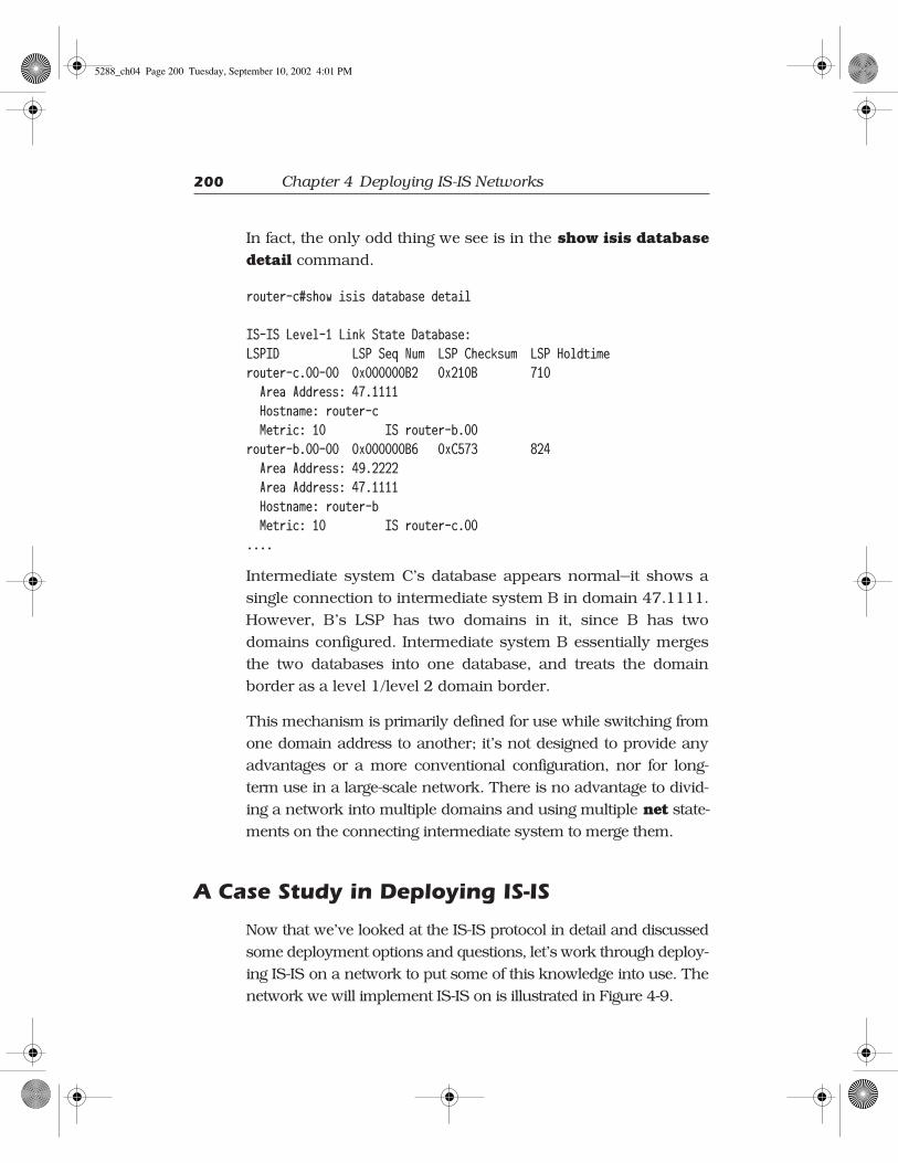
In fact, the only odd thing we see is in the show isis database
detail command.
router-c#show isis database detail
IS-IS Level-1 Link State Database:LSPID LSP Seq Num LSP Checksum LSP Holdtime router-c.00-00 0x000000B2 0x210B 710 Area Address: 47.1111 Hostname: router-c Metric: 10 IS router-b.00router-b.00-00 0x000000B6 0xC573 824 Area Address: 49.2222 Area Address: 47.1111 Hostname: router-b Metric: 10 IS router-c.00....
Intermediate system C’s database appears normal—it shows a
single connection to intermediate system B in domain 47.1111.
However, B’s LSP has two domains in it, since B has two
domains configured. Intermediate system B essentially merges
the two databases into one database, and treats the domain
border as a level 1/level 2 domain border.
This mechanism is primarily defined for use while switching from
one domain address to another; it’s not designed to provide any
advantages or a more conventional configuration, nor for long-
term use in a large-scale network. There is no advantage to divid-
ing a network into multiple domains and using multiple net state-
ments on the connecting intermediate system to merge them.
A Case Study in Deploying IS-IS
Now that we’ve looked at the IS-IS protocol in detail and discussed
some deployment options and questions, let’s work through deploy-
ing IS-IS on a network to put some of this knowledge into use. The
network we will implement IS-IS on is illustrated in Figure 4-9.
5288_ch04 Page 200 Tuesday, September 10, 2002 4:01 PM

A Case Study in Deploying IS-IS 201
While this is a simple network in many respects—for instance,
it’s a two-layer design rather than a three-layer design—it will
provide some interesting areas of consideration for implement-
ing IS-IS. We’ll first consider some fundamental questions, such
as whether or not to divide the network into domains, and then
we’ll focus on each area of the network, and consider the design
and problems we might face in each one.
To Divide or Not to Divide
The first question we need to answer when looking at
implementing IS-IS on this network is whether to divide it into
domains or leave it as one large area. Since this is a
ISP
ISP
DM
Z10
.1.12
7.0/2
4
CorporatePartner
IT Lab10.3.0.0/16
Remote Sites10.1.0.0/24 through 10.1.120.0/24 Remote Sites
10.4.128.0/24 through 10.4.250.0/24
Data Center10.2.0.0/24 through 10.2.15.0/24
Figure 4–9 Network for IS-IS implementation case study
5288_ch04 Page 201 Tuesday, September 10, 2002 4:01 PM

202 Chapter 4 Deploying IS-IS Networks
moderate-sized network (it is about 300 routers), it could easily
be placed in a single routing domain. If we decided to place it in
a single domain, would we place it in a single L2 domain or a
single L1 domain? Our choice would be to place it in a single L2
domain, for the reasons we described in “Putting the Network in
One Routing Domain,” earlier in this chapter.
However, there are a number of good reasons to break this net-
work into separate level 1 and level 2 domains. For instance,
the IT lab probably wants to be separated from the network in
some way, so any experiments going on there have minimal (or
no) impact on the rest of the network. At the same time, the IT
lab would like to receive full routing information from the net-
work, so this information can be recorded and fed into the test
networks for various purposes (rather than relying entirely on
network topology generators).
The most compelling reason to break the network into areas is,
of course, so we can discuss the process of breaking the net-
work into areas and describe how to handle the various issues
that arise when doing so. Let’s begin by determining that we
should break the network into separate level 1 and level 2 rout-
ing domains.
Dividing the Network
Once we’ve decided to divide the network, where should the
dividing lines be? Looking at Figure 4-9, there appear to be sev-
eral areas of the network which naturally fall into domains.
• The remotes sites could fall into a single L1 domain, or
two L1 domains.
• The data center could be placed within an L1 domain.
• The IT lab could be placed in its own L1 routing domain.
5288_ch04 Page 202 Tuesday, September 10, 2002 4:01 PM

A Case Study in Deploying IS-IS 203
• The DMZ and connection to the Internet and the
corporate partner could be placed in a separate L1
domain.
• The remainder of the intermediate systems, the core of
the network, could be placed in an L2 routing domain.
❖ Note: The term DMZ, or Demilitarized Zone, comes
from the common practice of having an area between two
countries which is demilitarized, or that no arms are
allowed into, with checkpoints and other safeguards
between the DMZ and the country proper. In networking,
the DMZ is the area between an untrusted network and
the internal (trusted) network where security is
implemented, or where servers and other devices are
located without compromising the integrity of the trusted
(internal) network.
With this set of domains as our background, let’s look at each
section of the network and determine what design challenges
we are going to face in each one.
Remote Sites
We’ll begin our tour of the network by examining several
issues in handling the remote sites, beginning with IP address
summarization.
Remote Site Summarization
Figure 4-10 illustrates just the remote sites with their connec-
tions to the network core for reference.
These two sets of remote sites fall within two natural IP address
ranges, 10.1.0.0 through 10.1.120.0 and 10.4.128.0 through
5288_ch04 Page 203 Tuesday, September 10, 2002 4:01 PM

204 Chapter 4 Deploying IS-IS Networks
10.4.250.0. Since we are concerned with the ability to summa-
rize IP address spaces, and summarization is possible only at an
L1/L2 border, the best place to put this border is going to be at
intermediate systems A and B in Figure 4-10, where the remote
sites converge. One of the tasks entails configuring the links
towards the remote site routers as level 1–only links, and con-
figuring the links towards the remainder of the core as level 2–
only links.
IP summaries of 10.1.0.0/17 and 10.4.128.0/17 seem to be the
most natural summaries intermediate systems A and B could
advertise: they would cover 10.1.0.0/24 through 10.1.127.0/24
and 10.4.128.0/24 through 10.4.255.0/24. There is an obvious
problem with the lower of these two summaries, 10.1.0.0/17,
since 10.1.127.0/24 is being used as the DMZ connecting this
DM
Z10
. 1.1
27. 0
/24
Remote Sites10.1.0.0/24 through 10.1.120.0/24(120 remote sites)
A
B
C
D
Remote Sites10.4.128.0/24 through 10.4.250.0/24(122 remote sites)
Figure 4–10 Remote sites
5288_ch04 Page 204 Tuesday, September 10, 2002 4:01 PM

A Case Study in Deploying IS-IS 205
network to external networks. Does the overlap mean that we
can’t summarize this address range?
No—remember that routers always make a forwarding decision
based on the longest prefix match, which means a router
switching a packet which could be switched based on two dif-
ferent learned paths will use the more specific one. Assume we
go ahead and summarize at intermediate systems A and B,
using the summaries indicated above. Intermediate system C
would then receive the following paths:
• 10.4.128.0/17, reachable through intermediate systems
A and B
• 10.1.0.0/17, reachable through intermediate systems A
and B
• 10.1.127.0/24, reachable through intermediate system D.
If intermediate system C receives a packet destined to 10.1.1.1,
for instance, it would switch it along the path available to
10.1.0.0/17, as this is the only match for the destination of the
packet. If, however, intermediate system C receives a packet
destined to 10.1.127.1, it will find that the packet’s destination
address matches both 10.1.0.0/17 and 10.1.127.0/24. Because
10.1.1127.0/24 has a longer prefix length (is more specific), C
will route the packet along that path towards that destination.
The next issues we must consider when summarizing two
points in the network are routing black holes and suboptimal
routing on link failure. Suppose that we’ve configured the
10.1.0.0/17 summary on both intermediate systems A and B,
and we then lose the link between A and some remote site, say
10.1.0.0/24, as illustrated in Figure 4-11.
Even though this link fails, intermediate systems A and B will
still be advertising the 10.1.0.0/17 summary to C and the rest of
5288_ch04 Page 205 Tuesday, September 10, 2002 4:01 PM

206 Chapter 4 Deploying IS-IS Networks
the core. Suppose that C chooses the path through A instead of
the path through B. If there is filtering of some type in place, A
simply might not know about the path through E and will drop
the packets (see the earlier section “Routing Black Holes”).
If A does know about this alternate path (which is generally the
case in an IS-IS network), it will send the packets along to E,
which will then forward the packets to B, which will then for-
ward them to the intermediate system F. Of course, if these are
truly remote sites, the links between these sites and the hubs
will most likely not be sized to handle the traffic for two sites.
For example, in this case the links between E and intermediate
systems A and B will likely become overwhelmed and either fail
or cause some traffic to be dropped.
The most common solution to routing black holes and subopti-
mal routing is to make certain that some other link, designed to
10.1.0.0/24
10.1.0.0/17
10.1.0.0/17
10.1.1.0/24
A
B
C
F
E
Figure 4–11 A routing black hole and suboptimal routing
5288_ch04 Page 206 Tuesday, September 10, 2002 4:01 PM

A Case Study in Deploying IS-IS 207
handle the traffic load, is available between intermediate sys-
tems A and B within the level 1 routing domain. Here the direct
link between A and B should be placed in the level 1 routing
domain, along with the remote sites. As a result, traffic received
by A, and destined to the remote site, will traverse the link to B
and then be routed to F.
Remote Site Optimal Routing
Finally, we need to consider suboptimal routing within the level
1 routing domain created for the remote sites. Figure 4-12 illus-
trates this scenario.
For clarity, only one remote site, 10.1.120.0/24, is shown in
Figure 4-12. If intermediate systems A and B are setting their
attached bits, each remote site IS will choose one of the two
possible exit points, or it will decide to load share between the
two exit points, depending on what the metrics of each link are
within the routing domain. Let’s assume the network adminis-
trator wants to direct the traffic towards the data center through
intermediate system A.
We could accomplish the task with a number of techniques,
including the use of static routes. However, we’d rather use
something that relies entirely on the IS-IS protocol already
deployed in the network and requires minimal configuration
and maintenance. The most straightforward way to achieve
the desired result is to leak the routes to the data center into
the level 1 routing domain at intermediate system A, and not
leak them at intermediate system B. The remote sites would
now use the leaked routes to reach the data center, and the
default routes, which result from the attached bit set on A
and B, to reach all other destinations outside the level 1
domain.
5288_ch04 Page 207 Tuesday, September 10, 2002 4:01 PM

208 Chapter 4 Deploying IS-IS Networks
Remote Site Routing Domain
After considering each of the issues outlined in the section
above, the best option for the remote site intermediate systems
is to put them all in one domain, as illustrated in Figure 4-13.
The Data Center
Next, let’s consider how to handle the data center—should it be
a single level 1 routing domain? Figure 4-14 shows just this
area of the network for closer examination.
Outside
Remote Site10.1.120.0/24
A
B
(other remote sites omitted)
Data Center10.2.0.0/24 through
10.2.15.0/24
Figure 4–12 Suboptimal routing within the remote sites level 1 domain
5288_ch04 Page 208 Tuesday, September 10, 2002 4:01 PM

A Case Study in Deploying IS-IS 209
Remote Sites10.1.0.0/24 through 10.1.120.0/24(120 remote sites)
A B
Remote Sites10.4.128.0/24 through 10.4.250.0/24(122 remote sites)
L1/L2 IS10.1.0.0/17& 10.1.128.0/17
10.1.0.0/17& 10.1.128.0/17
Area 49.0100
Leak 10.2.0.0/24 through 10.2.15.0/24
Figure 4–13 Remote site level 1 domain
Data Center
10.2.0.0/24 through 10.2.15.0/24
G
H
I J
Servers attached here
Figure 4–14 The data center
5288_ch04 Page 209 Tuesday, September 10, 2002 4:01 PM

210 Chapter 4 Deploying IS-IS Networks
There are two primary considerations when we examine this
small piece of the network. The first is those parallel links
where all the servers are attached at the top, running between
intermediate systems G and H. While it might not seem like a
big deal, as the number of links increases, the number of dupli-
cate LSPs flooded along these parallel links could become
excessive. What can we do to cut down on the amount of flood-
ing in this area of the network?
The first solution we want to explore is to mark the interfaces to
which servers are connected as passive interfaces. This setting
allows IS-IS to route to and from the server links, but not
through them. Since these links probably were not sized with
the idea of transiting traffic over them, the result is acceptable.
❖ Note: Marking an interface passive in the Cisco IOS
Software instructs the routing protocol, in this case IS-IS,
to include the interface in any reachability information it
is transmitting to other intermediate systems, but not to
run the protocol over the actual link connected to the
interface. In practice, this means IS-IS will not transmit
hello packets over an interface which is marked passive
in the Cisco IOS Software.
Another option is to use a mesh group to prevent A and B from
excessively flooding across these links. They will still route traf-
fic across (through) each of these links, but they will not flood
any information across them. For this network, we’ll choose to
configure all the server links as a mesh group, and only to for-
ward information across the one direct link between these two
intermediate systems with no servers attached. This last task is
achieved by configuring a lower metric on that link.
Should we also worry about these links flooding into the rest of
the network? No, because intermediate systems G and H will
advertise only one link between them anyway. Intermediate
5288_ch04 Page 210 Tuesday, September 10, 2002 4:01 PM

A Case Study in Deploying IS-IS 211
system G will recognize, from the information in the hello pack-
ets, that all of these parallel links are connected to H, so it will
only include in its LSP one connection to H, rather than one for
every link.
The second consideration for this area of the network is if part
of it should be L1 only, or if this entire piece should be included
in the L2 routing domain. The three primary options seem to be
• Making the entire set of intermediate systems, G, H, I
and J, all part of the L2 routing domain.
• Making intermediate systems G and H a part of an L1
routing domain, while I and J are part of the L2 routing
domain.
• Making all four intermediate systems, G, H, I and J, a
part of an L1 routing domain.
Are there any major advantages or disadvantages to each of
these approaches? In this case the decision comes down to at
which point the summarization should occur. Since the data
center appears to be a self-contained unit behind just two inter-
mediate systems (G and H), we’ll opt to place them in the L1
routing domain. We can then summarize the 10.2.0.0/24
through 10.2.15.0/24 routes into just one advertisement. In
order to give the data center room to grow, we’ll summarize
10.2.0.0/16 on intermediate systems G and H. Figure 4-15 illus-
trates the results of these decisions.
The first approach, placing all the intermediate systems in the
level 2 domain, would prevent us from summarizing the infor-
mation in the data center because it would be advertised
towards the rest of the network. All four intermediate systems
are not placed in the level 1 domain because the ideal summari-
zation point is, in this situation, where the parallel links
converge.
5288_ch04 Page 211 Tuesday, September 10, 2002 4:01 PM

212 Chapter 4 Deploying IS-IS Networks
Connections to the Outside
There are several connections to outside networks; Figure 4-16
illustrates this part of the network.
We’ve added a bit more detail in Figure 4-16 about the connec-
tions to outside networks, including routers that belong to the
Internet Service Providers or partners and their routing protocol
connections. Should this small group of intermediate systems
be placed in their own level 1 routing domain?
At first glance, it looks like there will probably be a good num-
ber of destinations learned from these various outside connec-
tions. However, all those routes (potentially full Internet routing)
Data Center
10.2.0.0/24 through 10.2.15.0/24
10.2.0.0/16
10.2.0.0/16
G
H
I J
L1/L2 IS
Servers attached here
Figure 4–15 Summarization within the data center
5288_ch04 Page 212 Tuesday, September 10, 2002 4:01 PM

A Case Study in Deploying IS-IS 213
are carried by BGP and are isolated only to the routers running
that protocol. In any case, we still need to propagate, somehow,
reachability information about the external prefixes to the rest
of the network. To avoid overloading the IS-IS databases with
that information, and because all the exits can be reached
through intermediate system K, it is easier to just propagate a
default route.
Where should the dividing point between this area and the level
2 routing domain within the core be? It could be either on inter-
mediate systems D or K, or on intermediate systems C and J.
The biggest advantage to including D in the level 1 routing
domain, but not C or J, is that all the configuration required to
block the external information within the level 1 area into the
core of the network can be placed on a single intermediate sys-
tem; we can also isolate the DMZ inside the level 1 domain.
ISP
10.2.0.0/16
default & all others
10.3.0.0/16static redistributed
leak all
10.2.0.0/16
ISP
CorporatePartner
IT Lab10.3.0.0/16
10.1.0.0/17& 10.1.128.0/17
10.1.0.0/17& 10.1.128.0/17
Area 49.0100
Area 49.0200
Area 49.0400
Area 49.0300
Leak 10.2.0.0/24 through10.2.15.0/24
Fig 04-19Figure 4–16 Connections to the outside of the network
5288_ch04 Page 213 Tuesday, September 10, 2002 4:01 PM

214 Chapter 4 Deploying IS-IS Networks
We’ll follow this design—intermediate systems D and K in the
level 1 routing domain, while C and J are not in it—for simplicity
of configuration.
The primary information we want this area to provide to the
level 2 routing domain is the default route, so that hosts and
servers within the network can reach devices connected to the
Internet and the corporate partner’s network. We can do this
using the ability to originate a 0.0.0.0/0 default route on a L1/
L2 router into a level 2 routing domain.
There is also the issue of the DMZ itself, which is the 10.1.127.0/
24 network. We summarized around this range when we were
working on the design for the remote sites, so we need to be care-
ful that we maintain reachability to this segment from the rest of
the network. In this case, the reachability to the DMZ is main-
tained automatically through the advertisement of level 1 infor-
mation to the level 2 domain by intermediate system D.
Finally, we need to consider the BGP connections, both internal
and external. It might be good to use the IS-IS ability to set the
overload bit while BGP is converging on the three border inter-
mediate systems to avoid black holing traffic unnecessarily. Fig-
ure 4-17 illustrates the results of these design decisions.
Connecting to the Lab Network
Finally, let’s consider how we should handle the connection of
the lab to the production network. This small piece of the net-
work is illustrated in Figure 4-18.
The primary issue when dealing with a network lab connected
to a production network is to protect the production part of the
network from mistakes and the constant changes propagating
from the lab. To do this, it’s best to isolate the lab network as
5288_ch04 Page 214 Tuesday, September 10, 2002 4:01 PM

A Case Study in Deploying IS-IS 215
much as possible. Rather than summarizing at the connection
point between the lab and the production network, we’ll use a
static route which is redistributed into IS-IS at the L1/L2 border.
ISPJ
D
K
C
ISP
DM
Z10
.1.1
27.0
/24
CorporatePartner
eBGP
iBGP
iBGP
iBGP
eBGP
eBGP
49.0200
L1/L2 IS default & allinformation
BGP overload bit interaction
Figure 4–17 The design of the outside connections
IT Lab10.3.0.0/16
C
L
Figure 4–18 The IT lab
5288_ch04 Page 215 Tuesday, September 10, 2002 4:01 PM

216 Chapter 4 Deploying IS-IS Networks
The redistribution will prevent any accidental inflows of infor-
mation into the level 2 routing domain and isolate all routing
changes from leaving the level 1 domain.
On the other hand, the IT lab is going to want access to the
whole routing table information from the production network,
so it can be used in testing and for monitoring. To do this, we
need to configure the level 1/level 2 border with full route leak-
ing, so the entire level 2 routing table is leaked into the lab
network.
Where should the level 1/level 2 routing domain border be
placed? The most logical place, at first glance, is on intermedi-
ate system L. However, giving the lab a little buffer intermediate
system within the level 1 routing domain, where further filtering
and access control can be placed, may not be a bad idea, so
we’ll place the level 1/level 2 border between intermediate sys-
tem A and the remainder of the core.
Final Design
Figure 4-19 illustrates the final layout of the routing domains.
Sample Configurations
This section contains sample configurations for some of the
intermediate systems in the case study. Only the L1/L2 router
configurations are included, and only the relevant parts to the
case study are shown.
hostname IS_A!! Intermediate System A: L1/L2 intermediate system in domain 49.0100. ! The routes from the Data Center are leaked through this node into the
5288_ch04 Page 216 Tuesday, September 10, 2002 4:01 PM

A Case Study in Deploying IS-IS 217
! level 1 domain. The reachability information from the remote sites is ! summarized in two blocks.!interface POS1/0 description Template for interfaces facing the core. ip router isis isis circuit-type level-2-only!interface Serial3/1 description Template for interfaces facing the remotes. ip router isis isis circuit-type level-1!router isis summary-address 10.1.0.0 255.255.128.0 summary-address 10.4.128.0 255.255.128.0 redistribute isis ip level-2 into level-1 distribute-list 101 net 49.0100.0000.0000.000a.00 metric-style wide
ISP
10.2.0.0/16
default & all others
10.3.0.0/16static redistributed
leak all
10.2.0.0/16
ISP
CorporatePartner
IT Lab10.3.0.0/16
10.1.0.0/17& 10.1.128.0/17
10.1.0.0/17& 10.1.128.0/17
Area 49.0100
Area 49.0200
Area 49.0400
Area 49.0300
Leak 10.2.0.0/24 through10.2.15.0/24
Fig 04-19Figure 4–19 Routing domain and routing layout
5288_ch04 Page 217 Tuesday, September 10, 2002 4:01 PM

218 Chapter 4 Deploying IS-IS Networks
log-adjacency-changes!! access-list that allows the leaking of only the Data Center routes.!access-list 101 permit ip 10.2.0.0 0.0.255.255 255.255.0.0 0.0.255.255!
hhhhoooossssttttnnnnaaaammmmeeee IIIISSSS____BBBB!! Intermediate System B: L1/L2 intermediate system in domain 49.0100. ! The reachability information from the remote sites is summarized in ! two blocks.!interface POS1/0 description Template for interfaces facing the core. ip router isis isis circuit-type level-2-only!interface Serial3/1 description Template for interfaces facing the remotes. ip router isis isis circuit-type level-1!router isis summary-address 10.1.0.0 255.255.128.0 summary-address 10.4.128.0 255.255.128.0 net 49.0100.0000.0000.000b.00 metric-style wide log-adjacency-changes!
hhhhoooossssttttnnnnaaaammmmeeee IIIISSSS____CCCC!! Intermediate System C: L1/L2 intermediate system in domain 49.0400. ! All routes are leaked into the level 1 domain, while all reachability ! information local to the domain is prevented from propagating into the ! core. Reachability to the IT Lab is maintained by redistributing a ! static route.
5288_ch04 Page 218 Tuesday, September 10, 2002 4:01 PM

A Case Study in Deploying IS-IS 219
!interface POS1/0 description Template for interfaces facing the core. ip router isis isis circuit-type level-2-only!interface POS2/0 description Interface facing intermediate system L. ip router isis isis circuit-type level-1!! First off, the static route (10.3.0.0/16) is redistributed only into ! level-2. All IP reachability is denied from propagating outside the ! level 1 domain and all level 2 routes are leaked into level 1.!router isis redistribute static ip level-2 redistribute isis ip level-1 into level-2 distribute-list 102 redistribute isis ip level-2 into level-1 distribute-list 103 net 49.0400.0000.0000.000c.00 metric-style wide log-adjacency-changes!! The static route points to the Null0 interface because specific ! information should be learned from intermediate system L. The route ! prevents any type of instability from being propagated into the core.!ip route 10.3.0.0 255.255.0.0 Null0!! These access lists control the flow of information between level 1 and ! level 2 (all denied by 102) and vice versa (all permitted by 103).!access-list 102 deny ip any anyaccess-list 103 permit ip any any!
hhhhoooossssttttnnnnaaaammmmeeee IIIISSSS____DDDD!
5288_ch04 Page 219 Tuesday, September 10, 2002 4:01 PM

220 Chapter 4 Deploying IS-IS Networks
! Intermediate System D: L1/L2 intermediate system in domain 49.0200. A ! default route is originated so that the whole network can reach the ! external destinations (ISPs and Corporate Partners).!interface FastEthernet0/0 description DMZ ip address 10.1.127.1 255.255.255.0 ip router isis isis circuit-type level-1!interface POS1/0 description Template for interfaces facing the core. ip router isis isis circuit-type level-2-only!! The default-information originate command creates a default route into ! the level 2 domain; in this case, into the rest of the network.!router isis default-information originate net 49.0200.0000.0000.000d.00 metric-style wide log-adjacency-changes!! IS_D is not running BGP, so it needs a default route itself to reach ! IS_K (10.1.127.2), which has full routing information.!ip route 0.0.0.0 0.0.0.0 10.1.127.2!
hhhhoooossssttttnnnnaaaammmmeeee IIIISSSS____GGGG!! Intermediate System G: L1/L2 intermediate system in domain 49.0300. ! The Data Center routes are summarized and a mesh group is used to ! prevent excessive flooding.!interface FastEthernet0/0 description Template for the server links.
5288_ch04 Page 220 Tuesday, September 10, 2002 4:01 PM

A Case Study in Deploying IS-IS 221
ip router isis isis circuit-type level-1 isis mesh-group 1!interface POS1/0 description Template for interfaces facing the core. ip router isis isis circuit-type level-2-only!! The circuit type for the POS2/0 link is the default (level-1-2). The ! link is placed in the same mesh group as the other links to prevent ! excessive flooding. Only the level-1 metric needs to be lowered (it ! is 10 by default), as we only want to favor intra-domain traffic ! between the two intermediate systems.!interface POS2/0 description Link to IS_H with no servers, lower metric. ip router isis isis metric 5 level-1 isis mesh-group 1!router isis summary-address 10.2.0.0 255.255.0.0 net 49.0300.0000.0000.0010.00 metric-style wide log-adjacency-changes!
hhhhoooossssttttnnnnaaaammmmeeee IIIISSSS____HHHH!! Intermediate System H: L1/L2 intermediate system in domain 49.0300. ! The Data Center routes are summarized and a mesh group is used to ! prevent excessive flooding.!interface FastEthernet0/0 description Template for the server links. ip router isis isis circuit-type level-1
5288_ch04 Page 221 Tuesday, September 10, 2002 4:01 PM

222 Chapter 4 Deploying IS-IS Networks
isis mesh-group 1!interface POS1/0 description Template for interfaces facing the core. ip router isis isis circuit-type level-2-only!! The circuit type for the POS2/0 link is the default (level-1-2). The ! link is placed in the same mesh group as the other links to prevent ! excessive flooding. Only the level-1 metric needs to be lowered (it ! is 10 by default), as we only want to favor intra-domain traffic ! between the two intermediate systems.!interface POS2/0 description Link to IS_G with no servers, lower metric. ip router isis isis metric 5 level-1 isis mesh-group 1!router isis summary-address 10.2.0.0 255.255.0.0 net 49.0300.0000.0000.0011.00 metric-style wide log-adjacency-changes!
Review Questions
1. What layers is a network normally divided into in a
three-layer design? A two-layer design?
2. Why does putting all of the intermediate systems in a
single domain simplify the configuration of the devices in
the network?
5288_ch04 Page 222 Tuesday, September 10, 2002 4:01 PM

Review Questions 223
3. How can you summarize IP addresses or hide
information in a network consisting of a single large
routing domain?
4. Why should you consider the results of a domain
partition when deciding how to build an IS-IS network
with multiple domains?
5. Why should you consider IP route summarization when
dividing a network into multiple routing domains?
6. What is the point of summarizing IP addresses?
7. How does the setting of the different timers affect
convergence in a network?
5288_ch04 Page 223 Tuesday, September 10, 2002 4:01 PM

5288_ch04 Page 224 Tuesday, September 10, 2002 4:01 PM