Embed Size (px)
Citation preview

-.\ .
. -'
. liMa PUBUCA TIO~S CO~ifPAcros (LEl'>.im·'G S':CTION)
COl\lThIONWEALTH OF AUSTRALIA
DEPARTMENT OF NATIONAL DEVELOPMENT
BUREAU OF MINERAL RESOURCES, GEOLOGY AND GEOPHYSICS
BULLETIN No. 35
THE INVESTIGATION OF DEEP
LEADS BY THE
SEISMIC REFRACTION METHOD
by
D. F. URQUHART
sued under the authority of Senator the Hon. W. H. Spooner, M.M. :Minister for Natioll
oal Development
r-:i-:R 8'5';(94) BUL..45 W55.
to~,~ ,I
1956

, 087668 -t-
" : COMMONWEA.l-TR,OF AUSTRALIA
:.',DEPARTMENT OF NATIONAL DEVELOPMENT, . BUREAU' of' MI~E,RA~ REsOU,~iES, GEQLOGYAND: GEOPHYSICS
BULLETIN No. 35
THE INVESTIGATION OF DEEP
LEADS BY THE , I. •
SEISMIC REFRACTION, ME!fHOD
by
D. F. URQUHART
Issued under the authority of Senator the Hon. W. H. Spooner, M.M. Minister for, National. Dev~l.op'l1en~ ,
, ,i956 , C.S523'55.
DEPARTJ\,lENT OF NATIONAL DEVELOP.tvlENT
1 ~;/. '[ ," ~ '~"-' • ,
Miiiisrer-'-"SENATOR THE HON. W. H. SPOONER, M.M.
Secretary - H G. RAGGATT, C.B.E.
BUREAU Of MINERAL RESOURCES, GEOLOGY AND GEOPHYSICS
Director-P. B. NYE, O.B.E . . ~. ··DeputyDm·cto.r - J. M. RAYNER
, ' " . . ~ '~~'. '- ~ ( . - - ~~ ~ ,.
This Bulletin was prepared in the Geophysical Section
ChIef GeophyslCist:-: R. F. THYER

CONTENTS
PAGE
ABST,RACT v,
INTRODUCTION 1
OCC~RRENCE OF DEEP LEADS IN AUSTRALIA I'
GEOPHYSICAL METHODS USED L" THE INVESTIGATION OF DEEP LEADS 2
8EIS~IIC REFRACTION METHOD 3, , I
GEOPHYSICAL SURVEYS FOR DEEP LEADS IN AUSTRALIA 10, I KALGOORLIE, WESTERN AUSTRALIA 10 ! Introduction. . 10
Geology 11' t Geophysical Problem and Methods Used 12
Results and Interpretation 13 Conclusions 17
ARDLETHAN, NEW SOUTH WALES 17 Introduction. . 17 Geology 18 Application of the Seismic Refraction Method 18 Results and Interpretation 19 Conclusions 20
WELLINGTON, NEW SOUTH WALES
Introduction .' Geology Application of the Seismic Refraction Method Results and Interpretation Drilling Recommendations Acknowledgments
REFERENCES ••
ILLUSTRATIONS
TEXT FIGURES.
1. Ray paths and time-dist1tnce curve for three-layer case
2. Ray paths and time-distance curve for two-layer case, dipping at an angle D
3. Reciprocal method for two-layer case, and error involved
20 20 21 21 22 24 24
24
PAGE
4
with interface 5
4. Change in bedrock level wit.h irregular interface (t.wo layer-case)
6
8
.' 'iii
PLATES.
1. -,-Kalgooriie, W~A. Portion of alluvial I~l'ea an~l. approxil~late loc~tion,_ of 1 gravity ancl seismic traverses
2. Kal(5?ol'lie, W.A. Seismograph ancl gravity profiles
B."Arcl!~than, - N.S.W,. -Lo~ation, of tin mines, !tp-cl seismog~'ajlh _ traverses
4. 'Arcllethan, is.s. ,,-r. S!')islUogl'lLph l)rofi!~s
5. Anllethall, N.S. ~'. Seismograph'tr:tverses and probable bedrock contours-
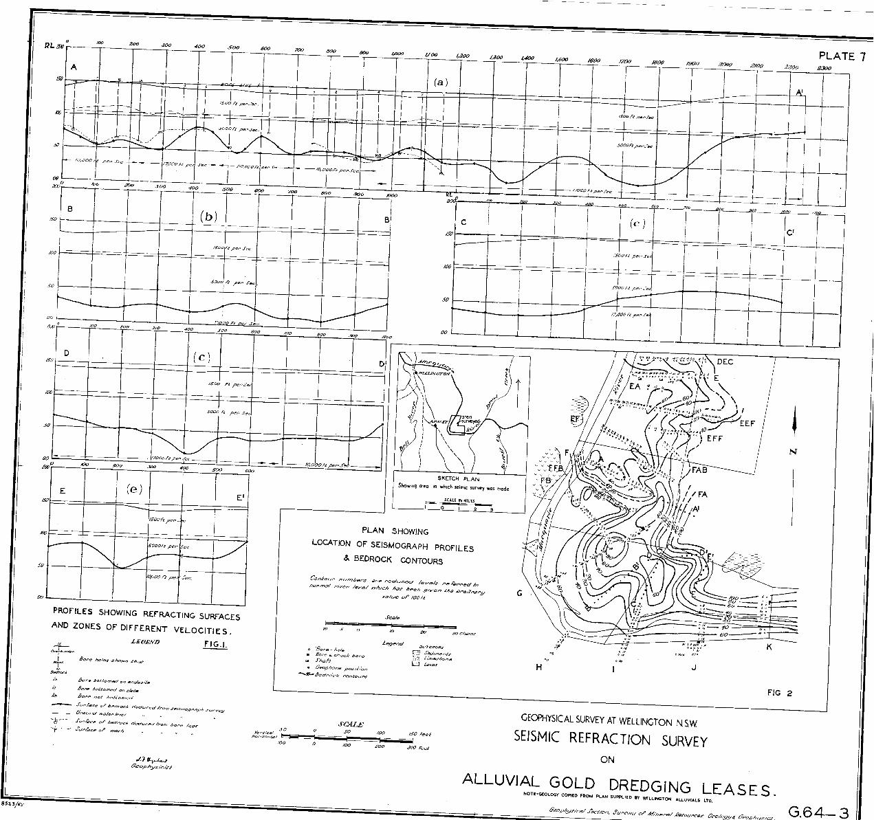
6. \\'ellington, N.S.~'. 'Geology, ,and location of seismic survey
7. Fig. ,1. ~rel,l~ngton, N.S.W.
-Fig, .2. W"JIjngton, :N.S.W. eont-olll'S
1 ::1 ; '-',::J
'S-eismograjJh profiles
'r:oca~ion' of sei~m~~r~Ph profil~~ a~d beclrock J
,',j v
At back
of :report.
ABSTRACT.
Deep alluvia'l leads of Recent, Pleistocene, and Tertiary age have been of considerable economic 'importance in Australian mineral production. Numerous basalt-covered and alluvium-covered auriferous leads have been worked in New South Wales and Victoria, but are quite rare in other states. However, important stanniferous deep leads have been worked at Herberton in North Queensland.
-, - f
Several geophysical methods can be applied to the investigation of alluvium-covered leads, the seismic refraction method being generally the most suitable. In the case of basalt-covered leads the geophysical problem is more difficult, although satisfactory results have been obtained by the magnetic -m.eJhod at Gulgong, New South Wales, and at Herberton. "
More recently (1948-49) the seismic refraction method has been applied to problems of this nature at Kalgoorlie, Western AustraJioa, and Wellington and Ardlethan in New South Wales.
At Kalgoorlie, geological evidence indicates that deep auriferous lead: .day extend ·for some distance to the south of the main Kalgoorlie lodes. At the request 'of the Western Mining Corporation, seismic refraction profiles were obtained along two 7-mile traverses. The first traverse ·(A) was about 15 miles south of the mines and the second (B) about 2 miles to the south of the "golden mile". The refraction profile revealed two deep' channels crossing traverse A and two channels crossing traverse B; the depth to bedrock on both traverses was, 'however, much greater ,than anticipated.'
For some years aHuvial gold has been dredged along the ban!<s of the Macquarie River near Wellington, New South Wales. In order to plan the course of the dredge, a considerable amount of 'advance drilling and 'sampling has to be done <by ,the company concerned. It was considered that the seismic method might be employed in order to reduce the 'amount of test drilling which ha's to be done. In 1949, the method was tried in this area but it was found to be too costly in this -application, due -tc the poor transmission qualities of the overburden which necessitated the use of -large charges or the drilling of deep shot holes. However, the limited amount of work which was done did indicate the unexpected presence of deep ground in a part of the area which had not been tested by boring.
In the past, small stanniferous lodes have been worked about 6 miles to the north-west of Ardlethan. The geological evidence suggested that alluvial tin, shed from the Bygoo deposits, might be found at shallow depth. The seismic 'refraction method was used once again, but it was found that the depth to bedrock was much greater than had 'been anticipated. However, the pre~ence of a deep gutter, running in a north-easterly direction from the old workings, was fairly well established and drilling recommendations were made to th~ company concerned.
v

INTRODUC),ION.
Alluvial gold deposits of Recent, Pleis'tocene, and Tertiary age have been of considerable economic importance in Australian mineral production, ~hen the more easily won gold from 'the R~cent and Pleistocene deposits gradually became scarcer, the metal' was tr'aced 'by the more enterprising workers into the deep - alluvial leads, These leads represent the beds of old rivers which formed the surface drainage system in middle and late Tertiary times" M,any of the'leads are covered by a thick layer of basalt and/or 'alluvium and the depth of the drifts below the surface is therefore considerable, ranging' up to several hundred -feet, hence the term" deep leads ", To the author's knowledge the term was first applied to such gold deposits in New South Wales and Victoria, and is not in general use, Deep leads have also: been the source of most ()f, AustraIia's tin 'production, A description of the, manner in ~pich deep leads are formed, including details of the mechanism by which gold-bearing gravels and drifts 'are dep9sited, has 'been given by Kenny (1924), " -
There are :several geophysical methods which c'an be appiied, under certa~n drcumstances, to the location of deep leads or to the location of'the channels in bedrock in which the leads are' found.: By the application of ,these methods, much time-wasting and costly exploratory drilling can be eliminated.
This report gives a 'brief outline' of the occurrence of some deep 'leads in Australia and of .the geophysical work which has been done up to the present time: Three fairly recent geophysical investigations o{deep -leads are aescribed in detail and an outline is given of the theory and application of the seismic refraction method which was useq in these surveys.
'OCCURRENCE OF, DE~P LEADS IN AUSTRALIA.
Many deep leads have been worked' for gold in Australia, particularly in Victoria and New South Wales.
In Victoria, numerous gold-bearing leads occur in the Bendigo-BallaratStawell area and in the Rutherglen-Beechworth 'area. Other leads occur in Central Victoria and on the Dargo High Plains. The leads range in 'age froIrl
'Recent- to Tertiary and many of the earlier ones are covered by basalt flows, The leads are as much as 700 feet below the present surface, but few have been 'worked below 300 feet"
In New South Wales, deep leads have been worked over a wide 'area of New England and the central and southern tablelands, In general, the val'leY3 of ,the rivers ,flowing westward have been the most productive, but appreciable quantities of gold have also been won- from coastal rivers such as the Clarence and the Shoalhaven, As in Victoria, many of the earlier Tertiary leads haVe been covered by basalt flows, Example of basalt-covered leads are to be found at Trunkey, Ki'andra, and Gulgong, and alluvium-covered leads have been worked in :the Forbes-Parkes district and in the upper parts of the Shoalha'ven River, At Grenfell, and in the Corowa and Albury districts, leads have been worked 'at dep~s o~ 3.00 !eet and more,
.;;j f.. ~ •
- 'In~"lQueensland, most of the alluvial' gold has coine from Recent shallow '~,deposits~r: and there' are few of the deep' basalt-covered leads which are' so
COmmOn in. Victoria ani! New South -Wales: - - ' , ,-

2
Deep leads have been of relatively 'little economic importance in the other ~tates of Australia, although some have been worked in, Western Australia, e,g.,: at Kanowna and Kurnalpi, and il: the Norseman. 'area. Some gold has also. been won from deep Tertiary learu at Lefroy and Back~Creek in Tasmania:
-Most of the tin produced in Australia has come from Recent and Tertiary alluvial deposits, one of the most important deposits being in a sub-basaltic, deep lead system at Herberton, North Queensland. . . .
In New South Wales, tin has been -obtained from deep leads covered by basalt 'and alluvium. Shallow leads have also been worked in the Ardlethan district. r
A system of deep leads, some of them basalt-covered,' in t:he Ringaroom'a River area of North-East Tasmania, has yielded significa* quantities of -tin, Other, ·:but less productive, leads occur in the north-east· and north-west o,f the State. :
. Tin has also been won from deep leads in Western Australia, principally in the Greenbushes Field, in the south-west 'of the State. '
,GEOPHYSICA~ METHODS USED IN THE INVESTIGATION OF DE]i~P . LEADS.
The geophysical methods which can be applied to t,he investigation of 'deep alluvial-covered leads" are the seismic refraction, resi,stivity, gravity and magnetic methods. The seismic method is .described later in this report, and descriptions of all methods can be found in any stanp:ard text book on geophysics. By means:" of these methods it is sometimes possible to locate and :frace the course of buded' channels in an older land surface:' The seismic and 'resistivity methods may provide quantitative information about the depth and extent of such channels. The seismic method can, however, be applied mor~ generally than the resistivity method, and the interpretation of the results is usually more straightforward. The main disadvantages of the seismic method' are that it is more costly and usually slower than the other methods.
If there is sufficient density contrast between the alluvium filling a buried channel and the surrounding rock, a detectable anom.aly -in the earth';; gravitational field may be produced at the surface. It may therefore 'be pOS$ible to focate such a' channel by mapping the gravitational field intensity over the "area to be investigated. If reliable figures are available for the 'average density of the bedrock and the alluvium, it may. even be possible to '2st~mat:e the depth and extent of ,the channel. However, reliable qu<.ntitative 'results are not likely to be obtained by the use of the gravity meth'od alone.
In some instances, magnetite or ilmenite is associated with metallif.erous leads, and may be 'present in sufficient quantity to prQduce a measurable anomaly.in the earth's magnetic field intensity at the surface.
'When leads are covered by basalt flows, the direct location of the channel is more difficult. In some instances, however, the basalt flows have been restricted to the old river channels, and a method 'of'" delineating the basalt 'covering could be a useful guide in the investigation of a system of deep leads.' This is so with the Gulgong lead system (see page)O). ,", ',.
Wher,e conditions 'are suitabre, the use ot'geophysical 'methods '~a:y '~~~~lt in substantial savings in the time arid cost involved'in the prelimin~Tyristages of an exploratory programme 'for deep ·leads. The final- testing .forngoiqsior tin values can, of course, be done only by drilling, and ·sampling. . " l.:~ , )
3:
SEISMIC REFRA CTION METHOD
The seIsmIC method is based upon the fact that the velocity of propagation of mechanically generated waves through the earth's crust varies according to the elasticity of the media traversed, with the result that the direction of propagation may be altered at a boundary between two different media.
The wave velocity is given approximately by the expression:-
V=J3; where V = wave velocity
N = rigidity mod-;u.us D'= density of the medium traversed.
Fermat's principle of minimum time paths for light waves can also be applied to seismic waves. Thus," in travelling between two points the wave will follow a path along which velocities are of such magnitude that the travel time is a minimum ".
The laws of reflection and refraction "of light are also valid for the seismic ray. Hence in passing across a boundary between two media in' which the velocities of propagation are VI and V2 , the angle of refraction of the ray will be given by the expressi<?n, :-
Sin i VI
Sin r V z
where i = aJ.lgle of incidence . r = angle of refraction.
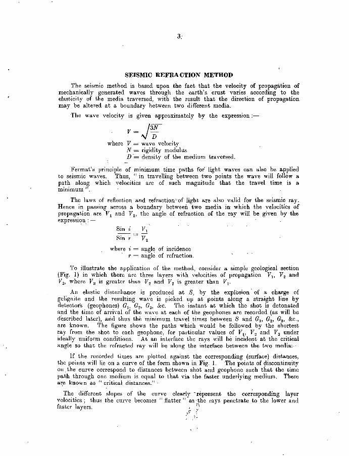
To illustrate the application of the method, consider a simple geological section (Fig, 1) in which there are three layers with velocities of propagation Vl> V2 and Va, where Va is greater than -l'2 and V2 is greater than VI'
An elastic disturbance is produced at 8, by the explosion' of a charge of gelignite and the resulting wave is picked up at points along a straight line by detectors (geophones) G1, G2 , Ga, &c. The instant at which the shot is detonated and the time of arrival of the wave at each of the geophones are recorded (as will be described later), alid thus the minimum travel times between 8 and G1, G2 , Ga, &c., are known, The figure shows the paths which would be followed by the shortest ray from the shot to each geophone, for particular values of Yl , Y 2 and 1'a under ideally uniform conditions. At an interface the rays will be incident at the critical angle so that the refracted ray will be along the interface between the two merua7-"
If the recorded times are plotted against the corresponding (surface) distances, the points will lie on a cun'e of the form shown in Fig. 1. The points of ~iscontinuity on _ the curve correspond to distances b.etween shot and geophone such that the time path through one medium is equal to that via the faster underlying medium, These a\e known as "critical distances." .
The different slopes of the curve clearly -represent the corresponding layer velocities; thus the ClUTe becomes" flatter" as -the rays penetrate to the lower and faster layers. . :"1
~~: : .. , . ,~ .

: --_ ...... --:,,' ~T
:e
~ ~
~
~ ~
~ . v,r,. . VI
-I[ ~,
, JI
H,= ~~ , SfI)L, =t'
H=~-- "V1 COJl'l
! .l(o~rl JCOJ.r]COSb,
N '
, V. 51flr1 "'" -
V,
'GI G/' Gl' G4 GS GG Gl' G8 G1 tiD Gil G'I/ 'f\ .,.d,;.L. - , , , I , TiT, r,
:' /~' _ " , '0 / r /, 'I V" I I I I I I H,
o ..;rr.:, ,. ,,',,""; .. ,',n 'L 1. I I I I I I I I' '\,<%)\ ~\\\ ~ \ \\ \ \ \ \ \ \ ~ \"\ \ \ \ \ \/ \ \)1 \ \ \/' \ ''/ \ ~.
/ / n r /i';'ff; 1 17 / / / lin 7 7 1 / 177 / / 1 // T F/I-/ / f / / /1 -shot pOint.
V,
GI,Gl etc - geophones
Fig. I.-Ray paths and time-distance curve for three-layer case.
The ,thicknesses (H1 and H 2 ) of the two top layers may be calculated from equations derived by Ewing, Crary and Rutherford (1937).
Co,
,For the, top layer:-:-. V T' H _ L 1
1 - 2 cos i1 (i)
where J\ = the intercept made on the time axis of the time-distance graph by that part of the curve representing the velocity V2 (Fig. 1)
For the second layer :-
T V '1'1V2 cos i2 H = 2 2
2 ' 2, cos r 2 2 cos r 2 C013 i1 (ii)
where 1'.2 = the intercept made on the time axis by that part of the curve corresponding to Va
, Sin i2 = Vdl'a'
5
'Iii practice it is often impossible to obtain all the 'required points on the time-distance curve by means of a single' shot (as shown, for simplicity, in 'Fig.' ,I), 'For example, with the equipment used' in the surveys :to be described here,: four geophones only could be used in t4e central spread' and it was necessary to fire a series of shots at increasing distances from' the geophone spread in order to obtain refractions from each of the surfaces, which were relevant to the particular problem. It is also necessary to increase the size of the charge as the shot point is moved farther away from the geophones.
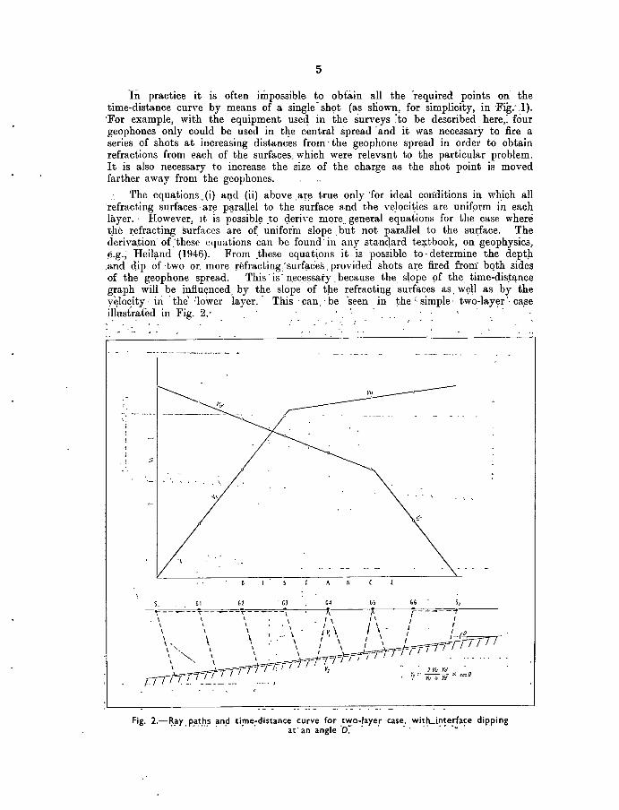
The equa,tions_(i) al,ld (ii) ,above ,are true only 'for ideal conditions in which all 'refracting surfaces' ar~ p~raUel to the surface and the velocities are unifprm in each layer" ,6:owever, It is possibl~ ,to Qeri\'e mQre .. general equations for the case where t,he r,efracting surfaces are of. unifor'm slope, but not parallel to the surface, The derivation' of .-these equations can be found' in any standard textbook, on geophysics; ¢,g,~ Heil;tnd (1946), From ,these equat~ons it is possible to' determine the deptp. ,and dip of ,two or, more refractinK'surfac'es "provided ,shots ate fired from bQth sides of the geophone spread, This' is' nec,essaty ,because the slope 9f the, time-dis~lj,nce graph will be influeI}ced. by the slope of tp.e refractillg surfaces as, w~ll as by the v~loqity' in 'the' :lower layer,' This 'pan 'be 'seen in the <simple' two-lay~r"ca.se i~ustrated in Fig, 2.' , ' ,
, '.
'\
A
. 1 Vu Vi' . ~] = VII + "i x cosO
Fig, 2.-~:ay, p_a,t,~,s ~n~tirne~distance curve for ,t'<~o-!aye!, 'case .. wit!Li~~e,':fa~e dippi ng at' an angle D.
6
'. Here, the slope of tlie time-{iistance graph gives an apparent; second-layer yclo.city .of F,,' for the' shot point at 8 1 (shooting" up-dip") and'a lower, apparent velocity Va for the shot point at 8 2 (shooting" down-dip "). The true, second-layer ~'~locity, V 2' can however, be found from the equation:- .
2VuVa .. V2 = ----- . cos D
V" + Va where D = the angle of dip ..
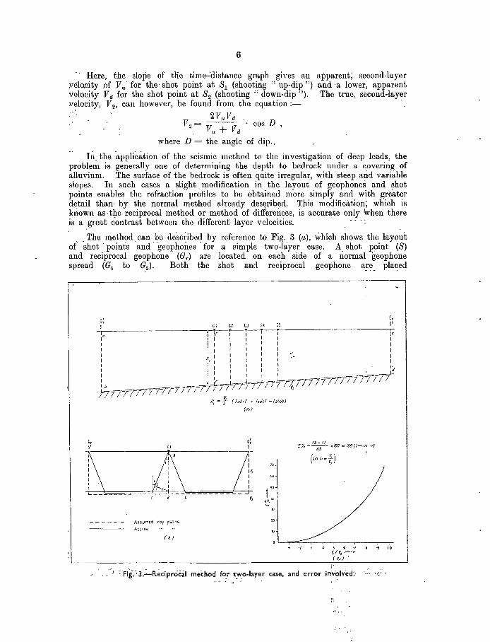
Ili. the 'application of the seismic method to the investigation of .deep leads, the problem is generally one of determining the depth to bedrock under a covering of alluvium. The surface of the bedrock is often quite irregular, with steep and variable slopes. In such cases a slight modification in the layout of geophones and shot points enables the refraction profiles to bc obtained more simply and with greater d~tail than· by the normal method already desqribed. This modification; which is known as.tl?-e reciprocal method or method of differences, is accurate only when there is a great contrast between the different layer velocities .
. . T.he method. can .. ~e described by reference to Fig .. 3 (a), which shows the layout of shot' points and geophones for a simple two-layer case. A. shot point (8) and reciprocal geophone (Gr ) are located on each side of a normal geophone spread (G1 to ~5)' Both the shot and reciprocal geophone are placed
G, S'
G; G, 5' S Gl Gl GJ G4 G;
I. .ir-Ti-i-r-------------r:. I I' I I I I I I I I ' I I I I I I I I I I I I I I I I .' I HI I I I I I I I r I I 1 I - I-: I I I I : . /
I ~" ~~1=d;rttrrrrrrr17FTl71 I b. ~ _. _ / I I T / I 7 I I I v,
-)77 n rF f I ? r; I / .
GI
JI, "'} (Tabcf -r Idef -rabde)
(<to)
G~ S
70
IV, I " I I ,10 v, ~40
'" "
AS- It[ f% --A-O- xlOO = IOO(!-CO~ vJ
(Sin v-f) ,
- - - - - - Assumed ray paths 10
Actual 10
., s "' ·1 V,/~.(c.-) :._
i'
• '0
) ~·Fig-.~3.~Reciprocal method for t.""o-Iayer case, and error in'volved:- '0"
t'

7
,beyond the critical distance so that the travel times recorded are' all for refracted rays, - A- second shot is ,fired at the point previously occupied' by the reciprocal geophone' (G r ),
If 'the velocity 1'2 is much greater than VI' the'ray paths through the upper layer will be almost ,'ertical. If this assumption IS made 'it can be seen by reference to the figrire that:~
" ,(abC! + Tedc! - T"bde = 2Tc! ' ,
, ,where Tilbcf = the recorded travel ,tjme for the path abcf,- and similll-rly for the other terms.
Hence the travel time for the path .cf is known alid if the velocity VI is also known, the depth to bedrock under the geophone Gl can be found. In the same way the depth to bedrock' under the other geophones can be calculated._
The error introduced by' the assumption of vertical ray paths depends on the ratio--Y-d-V2 and can' be easily calculated- by ·reference to Fig. 3 (b). It can be see~ from this figure that the time actually obtained by the method of differences is for the path A!!f) rather than for the r~quired distance AB. Hence the p~rcentage error '(E}-(due--to,-the assumption of vertical ray path) in the depth calculations IS
gIVen by the equation:- '
AB-AE E = 100
AB = 100, (1 - cos i)
,where sin i = Vt/V 2
This equation is plotted in Fig. 3 (c) for different values of Vt/V2 • It can be seen that if the ratio Vt/V2 is less than 0'45, the error introduced into the depth calculations will be less than 10 per cent., the calculated depth being less than the true depth by this amount. This curve can be used to make a correction to the depth calculations when the-ratio Vt/~2 is known. I
The reciprocal method can be applied in cases where .t~ere are- more than tWio layers. ,:After finding the thickness of the top layer, the shot points and l'eciproc~1 geophon~: are mO\ced out beyond the second critical distances. Vertical trahl times through the two layers are then obtained. The vertical travel time previously obtained for the' top layer is then subtracted, giving the time through the second layer and hence the thickness of that layer. The reciprocal method is particularly suitable for continuous profiling,_ beQause a separate value for the depth beneath each geophone is obtained, and once the layer velocities have been obtained fewer shots are r~quired for ,each spread than for the time-distance graph method.
The ,~lain source of error in seismic refraction metho~s is in ~~e Aetermination of the layer velocities. If there is no control provided by drilling in the survey area it is nece~sary to obtain the layer velocities from the time-distance graph. However, 'the' velocities so· obtained are for horizontal ray 'paths along the' surface of each layer, whereas the velocities, required for the depth calculations a-,:e for vertical ray
. paths ,thro~h ;each- layer.

'8
-. If there are drilLholes ayailable :in the: area of the survey it' may; be i)Qssible to measure the vertical velocity directly, either by placing a charge at the b'ottom of the drill hole and measuring the" up-hole time" to a geophone at the surface, -or, if the drill hole is to be preserved, it may be ,possible to lower a, geophone to the bottom of the hole and fire a charge at the surface,
Again, if the depth to bedrock is accurately known at certaiIi points iIi the survey area, a velocity may be assumed such that the ver~ical travel times obtained by reciprocal shooting are consistent with 'the known depth to' bedrock at those
'points. -', However, even when slich control is available, enors may be introduced by non-uniformity of the layer velocities over the region of the survey.
In shallow, refraction, shooting it ,is often possible, to, determine the trend of refracti~ surfaces beneath the shot points as well as th~ depth b~neath the geophone ~pread. The way 'in which this can be ,don~ ,can be se~n by refe!ence to the simple case illustrated in Fig. 4.
, Gd
.rl ,..I.
'f,
Gl Gl GI'
" s, " v,
v,
• Tr~~tl t"fI~S frota S. 5,
6' II S)
Fig. 4.-:-Change in bedroc:k level with irregular inte'rface (tw~-I,ayer case).
'Here, the last part of the time-distance' graph is displaced 'downwards'aS ,a result "> of th~ shallowing of the overburden between shot points '82 and 8 3,: : ,The 'chang~ in
the level of bedrock, H (relative to the surface), between 8 2 - !Lud -8 3 : is: approximate)y
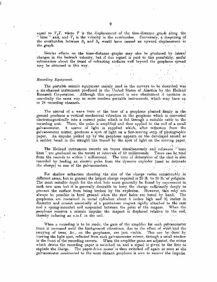
9
equal to l'tT, where T is the, displacement of the time-dista~ce ,graph ~long the " time" axis, and 1'1 is the velocity in the oyerburden. Conversely, a deepening of the overbl.lrden between 8 2 and 8a would have caused an upward displacement in the graph.
Similar effects on the time~istance ·graphs may ,also be . produced , by .lateral changes in the bedrock velocity, but, if due regard is paid to this possibility, usefril information about the trend of refracting surfaces well beyond the geophone s'pread mar be obtained in this way. ' .
Recording Equipment.
The portable seismic equipment mainly used in the surveys to be described was a six-channel instrument produced in the United States of America by the Heiland Research Corporation. Although this equipment is now obsolescent it operates in essentially the same way as more modern portable instruments, which may have up to 24 recording channels.
The arrival of a wave train at the base of a geophone planted firmly. in . the ground produces a vertical mechanical vibrat!on in the geophone which is converted electromagnetically into a current pulse which is fed through a suitable cable to the recording unit. There, the pulse is amplifie~' and then applied to the' coil of a :small galvanometer. A source of light, is supplied which, after, reflection from the galvanometer mirror, produces a spot of light on a fast-moving strip of photographic paper. An impulse picked up by the, geophone appears on the developed record as a sudden break in ~he straight line traced by the spot of light on the moving p3:per.
. -"\~, ... The Heiland instrument records six traces simultaneously and reference ," time
lines" are produced on the record at intervals of 10 milliseconds. Times can b~,'read from the records to within 1 millisecond. The time of detonation' of the shot· is' also recorded by feeding an electric pulse from the dynamo exploder (used to detonate the charge) to one of the galvanometers.
For shallow refraction shooting the size of the charge varies cohsiderably.in different areas, but in general the largest charge required is 20 lb. to 30 Ib:' of gclig[lite. The most suitable depth for the shot hole must generally be found by expeTIment in each new area but it is generally desirable to bury the charge sufficiently deeply to prevent the surface from being broken by the explosion. However, this may not always be possible in hard ground when the shot holes are bored by hand. The geophones are contained in metal cylinders, about 6 inches high and 3t inches in diameter and consist essentially of a permanent magnet rigidly attached to the case and a spring-mounted coil suspended between the poles of the magnet. ' Wh,en the geophone receives a seismic impulse the magnet is displaced relative' to the coil, the;reby inducing an e.mJ. in the coil.,
When a recording is to be made, the gain of the amplifier for each ga~vanoilleter trace is increased until the background vibrations, due to the effect of wind :and the swaying of trees; &c., on the geophones, are just visible. This cail be: do'ne' oy "iewing the light spot, reflected from each galvaJiometer mirror, through a small window i[l the front of the recording camera. When the amplifier gains are adjust"ed, the motor which drives the recording paper is s\\'itched on and a signal is given' to the' firer to explode the charge.' The paper-drive motor- is then switched off again as soon as tlie gah-anorileter conimected to the' most distant geopholHi is seen to receive'the impulse
to
GEOPHYSICAI~ SURVEYS FOR DEEP LEADS IN AUSTRALIA.
A considerable 'amount of experimental geophysical 'work, was done in Aust'ralia during 1929-1930 by the Imperi'al Geophysical Experimental Survey, and is fully described by Broughton Edge and Laby (1931). During this work four methods were tried over some of the deep leads of the Gulgong .gold field, New South Wales. Magnet~c and earth resistivity methods. were used over portions of the .leads which were covered by 'basalt, and_seismic and gravity methods were used in part of the a'rea where the covering 'of the leads was entirely alluvi'al. The most promising results were obtained by the magnetic method, which gave a good indication 'Of the boundaries 'and deepest par:ts of the basalt flows. The seismic' method did not show much. detail )n the surface 'Of the bedrock immediately below the alluvium, but this was probably due' to the II averaging out" effect of .the .time-distance· graphical method which was used.' in the depth calculations. The .reciprocal method would pr'obably have shown more detail.
. A further; more extensive magnetometer 'survey of the Gulgong . deep leads was made in 1930 by Rayner (1940). As a resul-t of this' survey it was possible to recomm~nd several unworked 'areas as being favourable for further ;t~st drilling. .,
Geophysical surveys have also been made over. the stanniferous deep leads at Tingha, N.S.W. (Rayner, 1933), Emmaville, N.S.W. (Rayner, 1937a). Stannum, N.S.W .. (Rayner, 1937b), and at Herberton in north Queensland (Thyer, Rayner and Nye, 193~). .
More recently, three geophysical .:surveys . for deep leads were carried . out by . the; Bureau of Mineral Resources.' These sU'rveys, which are fully described in the ensuing sections of this r~port, were 'at Kalgoorlie, Western Australia, 'in 1948, and at Wellington and Ardlethan in New South Wales, in 1949. In· 'all' three surveys the seismic refraction method was used, although a limited amount of gravity worri: was also done in the ~algoorlie survey.
The shallow, alluvial, ,auriferous deposit which was investigated in the Wellington survey was not, strictly speaking, a deep lead, ,out from the ge.ophysical aspe~t the problem was identical to .that ,involved in the investigation of deep lead's.
KALGOORLlE, WESTERN AUSTRALIA.
INTRODUCTION.
A preliminary seismic and gravity survey was 'made by the Bureau over an area near Kalgoorlie, Western Australi'a, in which a deep lead system
. was. believed to' .oc,c~r.
KalgoorIie, the western terminus of' the Trans-Australian R'ailway;, is approximately 320 miles east-north-east from F'erth, W.estern Australia.
Gold was discovered at Kalgoorlie· in 1893, and the area is now the greatest gold-producing centre in Australia. At present, practically all mining activity is confined to· the celebrated II Golden Mile" and, although this small area· maintains, ten different mining companies, a large proportion of the known are bodies 'has 'already been worked out. There is, therefore, 'an urgent need {or explQi-ation for further... major gold deposits in the a'rea, 'the development of which could ensure the .'future prosperity of Kalgoorlie.
1:1':
:>ri)e. rW~ern' ~Miriing . Corporation, in' . particular, . undertook·. ~ major eXploratory.programme and .the Corporation's geologists obtained much u~eful, geologi,cafdata. Ol!e aspect of this work involved the tracing of dett;ital gold: Which 'has 'been shed from the, Kalgoorlie reefs. This rep~rt deals with. the; preliminary geophysical survey which was made during the latter ~aU of. 194&, in an effort to locate 'any deep, lead wni,ch may eman.ate froJ'!l the' primary or~ bodies. , " - ,
:- The' 'writer wishes to' ackilowlE~dge the 'valuable assistance given dur.ing' 'llie c9urs~ of fhe survey by' Mr. ,D. Campbell, C,hief Geologist of Western: Mining' Corporation, and the members of his geological staff, .
',.:',The writ~r is al~o i~d~bted' to ~embers of the surVey and workshop staff of· Gold Mines of ~a'lgoorlie Ltd." for 'assistance given 'in surveying arid 'in: maintenance of the geophysical equipm~t. Also to the Western l\:finin-g', ~arage for' maintenance of the vehicle used ihlrougholJt the survey- -,
. '. . GEOLOGY •
.. . In a report by Clarke, (193~),special reference is made to the possibility that deep leads of considerable value may be found on the Western Australian goldfields. Ile points out the importance of the chains' of salt lakes running through the goldfields as a guide to an earlier drainage system, down which' eroded materIal containing' gold may have been carried. There is considerable controver~y 'as to, the true origin of these salt lakes, but Clarke suggests that the most likely theo'rY. is that they are the survival of early Cainozoic rivers. The .following extracts from his report are of interest. ' '
"EJpeirogenic l!Plift, very early'in the Cainozoic, raised 'at least all that part of the State which lies south of the Canning region. To visualize th~ amount of movement, one might take as datum a horizontal plane pdssing through 'a definite point in the prE;-Cambrian' complex, e.g .. the lOO-ft, leveJ in a mine at Kalgoorlie. During the Oretaceous submergence that plane would have' beeri' at lea'st 1,300' f~et ,lower than at present; at the climax 'of the EJocehe emergence it was cer.tainly at its present level and' probably higher. This' elevation was greatest' in' the north am! the period of emergence was long enough for the development of several consequent rivers, draining some to'the'south and some to the west."
At the maximum of the following Miocene submergence "'our imaginary datum plane would, in the north-west, be but little below sea level, while at Norseman it 'would be more than 't,OOO -fee't below it",' "','
. ," The gradual advances of tqe sea up the shallow valleys, excavated during the 'Eocene emergence, caused a re-'arrangement of the gravels, &c" iIi. those valley.!? and more detritus was add~d, :so that the valleys became partly ,filled: It is this material which forms the filling of the deep leads of the Goldfields.'"
, During the late Cainozoic emergence, '" the relative movEmient was greater in the 'south tha~ in. the,no~~ and was ?f the order o~ ?',OOO f~t." , :: .
, " The 'effect of the gradual uplift 'on the Central Goldfields was to 'cause a slow .. r.etreat of, the Miocene, sea, accompanied by' further 'working over 'of the fragmental deposits. -At the' same' time,- the depressions '6f the sea' floot.:'" direct desCendants of the early Cainozoic river 'system-became Iakes.H"~, .. -,
0.8523/55-2·

12.
'. > 'In a ·further· -reference· to these salt .lakes, ,Clarke writes .. " the remains of .'th~ Eocene drainage channels which ,'b.ad Ib~n .oniy~·partiaiIY::>-filled.hl :th~: lVliocene. "submergence 'are ·seen ,to a great degree. in the salt.}~kes~ys!;~; althotigh lateral" migration' of -some. of these . lakes has taken,. an,~ is taKmg;: place ;,..' ,:. '.' :, ,. .
. The question of the possible mIgration 'of these lakes is ·of some .imp6r~a~cd in' deciding upon a favourable area for initial prospecting for 'a buried channel. The direction of .. the··tnovetnent is known·to be from east to west-'--under the influence ·of the ~revailing westeriy. wi~ds~and 1ilthough the de:gree ~ of the·
. displacement' is not known' exactly,' it may be of tlie ·orct"er.6f-·several·miles: ,:'
The geology of the Golden Mile indicates that .the ore body: :vh.ich, is .now being. worked once ext~nded 'far' above the present erosion surface, ,and'iif 'SuC;h. is the case, considerable quantities ·of gold must have been removed fro~ : the area in ea:rlier' times. If the cnain of small salt lakes, shown in Plate: 1, to the 'south of Kalgoorlie provides a reliable'guide to the old drainage syStem; it. seems that the ma'in channel probably ran in,a south-easterly direction from Kalgoorlie and may now lie beneath the salt-bush Uats to the east of the ~alt l'akes. ,~". . '. --. -
Immediately tu .the. west of "these lakes' is a 'ridge of low hilI-s' ~~hning south-south-east U;n:ough Mt. Hunt,;and Feysville. Outcrops ·of. pni-Cambrhm greenstone· and sedim~ntsocqlF' along' tl1is :ridge. To the east ·of the hikes)s a stretch of fiat, sandy, salt-bush country terminated on the east by a"nothet . ridge consisting of. greenstone .running' through Boorara and Golden Ridge: The 'a-rea investigated consists of· a shallow valley about 7 miles wide; .lying. between the two ridges. ' .
. "/ . As. it result of extreme folding, rocks in. the area generally .dip very
.~.~~p'}y. The reg~onal strike. IS approxirriat~ly north-s.outh. ..
GEOPHYSICAL :PROBLEM AND METHODS USED.:
: ... : From the geophysicist's point of view the :problem reduces 'to th~' location' of' a huried 'chanrielor channels whiCh may'be ·anywhere beneath a- belt of fiat, alluvial cOUli.trY<ibout· 7 miles' wide, and' ·of- unknown depth .below;the present :surfaC€.· The investigation of an "area . as 'large ·as this 'would clearly be very slow and expensive by drilling alone. By locating the deep ground by geopJ:1ysical methods the drilling can.be localized_ to pla,ces where conc~ntrqtions Of -"gold could be expecterL . _ -, . : ~ '-' " . .' -' - ~ . ~
.. Th~ ul!imate ·aim of a' geophysical survey such as .this would "b~' to pr.oduce. ,a bedrock contour plan of the area:' The preliminary work which was done was -limited-- to' two traverses- (A aiid' B). aoout '9' miles -apart; runninO"
. approximately n-orth-easf across the ·shallow vaHey between 'the two . greenst6n~ ridges.' 'The position 'of' these two iraverses and a 'shorter 'one (A') - IS 'snown'
.. Qn' PIalEi'l. ;' ,. . - - - -.. .... ' .
. ;~" :·:A,;H~ilan.d 6-channel' porta'ble seismograph .was used in'the seismic su"i-vey. The shot holes· (up 'to '6 feet deep) were -put ;down with a post-hole digger: Charg~s up to 30 19. of 50 per cent. or ·60 per cent. S. N. gelignite were used and the~shot~ we.re fifed~by means of a standard dynamo exploder. Portion of :the firing· ~ulse' was Jed ',to one of the recording galvanometer~ hi order' to "register the_·zero ti~~ or shot instarit. HeHand;o{l-qainped geophol1es were tiSeo' fhrough the survey. ". . ' -' ' - '. ',:-

The field party consisted of one operator. and two field assiStants who were supplied by Gold, -Mines of Kalgoorlie Ltd. c! '
The reciprocal or difference method was used to' determine 'the depth to bedrock, and geophone spreads _ (each covering 300 ,feet) w,er,e, set up at intervals' of approximately 1,000 feet 'along the two main traverses (A and;B). In those' parts of the'traverses where the presence'of 'a channel was indicated, intermediate spreads' were added to obtain a' continuous refractIon profile in' tiio~ p'arfiCular 'sections:
. . ~ . . . 'It was 'also necessary to use short :spreads ,(geophones 10 to 20"feet,~p<1-rt)
to determine the velocity of the 'shallow sU'rface'layer whicJ:1 varied from 5 to 50 'feet in thicknesS. ' .
In' addition to traverses A and B, a refraction profile was obtained along a short traverse (A'), about three-quarters of a mile north of traverse A, (Plate 1).
Before commencing the seismic work a gravity survey was made along traverse A. Readings were taken 'at intervals of 100 feet; using a HeHand gravimeter with which changes· in gravity of less than 1 milligal can be measured with an accuracy of +0· 05 milligals. The gal (103 milligals) is the C.G.S. unit of acceleration (lcm/sec.2 ). Clianges of less than one pa~·t in a million ·of the 'earth's gravitational field can, therefore, be measured in this way. '
• . 'After 'completing the gravity traverse, seismic 'profiles were obtairied along traverses A, A' arid B, in' that order. .
For the surveying of the traverses the water level in the lakes was taken as the datum level arid given the arbitrary value of R.L.1,000 feet. ' At 'the tirii'e of the :survey there was a continuous stretch of water ,over the lake' country at the western end of traverses A and B which provided a convenient means of ,tying the levels of the two traverses.
RESULTS AND INTERPRETATION .
. - "The results of the gravity and seismic surveys are shown iri the form 'of' profiles "on Plate 2.
The gravity prOfile .
. 'The -relative gravity values observed at each station on traverse A' were corrected for drift, elevation and latitude effects, 'and after an 'arbitrari,da-ttirri~ value had been chosen, the reduced gravity values were plotted, producing the observed gravity profile on Plate 2. The outstanding feature of this ,profile ,is', the pronounced gravity" 'low" extending from the western end of the traverse to a'point,about 20,000 'feet east.:-It--is 'almost certain: that'a' gravity 'anomaly of this magnitude would be produced by a mass of relatively'light rock beneath; this section, rather than'a channel, in, the :sorface of bedrock: 'Two 'seco'itdliry-' " lows" occurring at 1l,500E and 29,!)QOE m;ly, on ,the other hand, _~present depressions' in ilie surface {j{ 'bed-rock. , Altho'l,lgh :it wouid ,have t>een. _diffi~ult. to Jna!<~ ~ny definit~ 'pre?icti~hS· oil. jh~ basi.~' pf -0.e~ ,r~ults ~lQ~e, "an.'8. tieinp.<. has been' madeAo-:carry the .analysis ot the graVIty, profile 'a little .furtiter-,in the light:o[ the results of the -seismic' work. ' 'I'l1is will ',be described, la-ter:.in':: this·report.- . " ., ' ".'" -, - , .. ',:
" .'

The seis1nic profiles.
The results of the seismic survey were, on the whole, satisfactory and~ channels in bedrock were detected at several points alo~g _travers~s A a~d B.
F~om the results ~btained, at each geophone spread, "~efraction profiles!' ~ were constructed (Plate 2), showing the boundary surfaces 'from which refracthms were obtained, and the, zones of different velocities of propagation,
, . ' "-. . . . The construction of the refraction profiles was based, on calclJl~tions:,of'
layer depth'S (by ,the reciprocal method) beneath each of the four central geophones in' each spread. Although' these stations were in many places 1,000 feet or more apart, the trend of the refracting· surfaces tn th~ regioll, between spreads could often be determined from a consideration of certain' eff~cts produced in, the time-distance graphs by the ,outer shots' ,of adjacent sprea~ds.
Over the greater part of the traverses three distinct layers were observed.
The top 'layer was found to be quite shallow over most of' the area, ranging in thickness from 1 or 2 feet to 50 feet; with an 'average value of abou't 20 'feet. The velocities observed for this layer were between 1;200 feet per sec. and 2,510 feet per 'sec. with a mean value of 1,830 feet per sec. on traverse A and' 2,010. feet per sec, on traverse B. It can be seen that 'on traverse A and the we.stern half of traverse B the top of the second layer maintains a r:early horizontal horizon at the level of the water in the lakes at the western ,end of the traverses, Due to heavy rain which fell early in 1948 there was a 'continuous stretch of water f.rom Hannan'sLake ,to Feysville at the time the survey was made.
The average velocity of the second layer was _ 6,100 feet per sec. on traverse A and -5,400 £.::'2t per sec,' on ' traverse, B. J:-!owever, towards the eastern end of traverS2' B the velocity of this layer was lower, namely 4,000 feet per sec,
The depth of the second layer ranged from a few feet to 300 -feet on traverse A and from 0 to 250 feet on traverse B.
The velocity of the third layer ranged between 11,000 and 20,000 feet per :sec. over both traverse A and traverse B, and, as the slope of the surf.ilce of this'zone was found to be very i-rregular, the velocities obtained are liable to' considerable error.
At a 'few parts of ,traverse A an interm~diate layer was detected. Velocities observed in this zone were in the range 8,000 feet per sec. to 11;000 feet ,per sec.
Interpretat'ion.
" The 'interpretation 'of the Irefraction profiIe~ was made by suh;tituting for the different velocities, geological' formations ]:taving elastic properties consistent with the' observed velocities and with ',t!Ie ,knqwn' local geology.' '
_ • • ~.'." r ~. .'. • •
'Duriqg the comparatively short history of geophysical exploraHon a' conside~.ilble amount ?f data ha·s been collected (particularly'hi. North America) concernm~ the .velOCIty characteristics of different 'sub-surface materials: ' An' analYllis, of this, information shows that .. when 'attempting' to"'diffeh~nHate" between -detrital' material and "country" rock an interpretation of. ;Yery --lbW:
and very high velocities can :generally be made 'without serious. error. For example, velocities from 600 to 2,500 feet per sec. are generally produced "?Y unconsolidated'in'oist" or dry sands, loams, clays ,and: l.90_se gravels, ,whIle velocities in the range 9,000 to 20,000 feet per sec. may',)b~'.Jta1<~n to rep~s~nt formations such 'as shale, sandstone, granite, basalt, limEtstqne, &c. Velocitie,s in the intermediate range (2,500 to 9,000 feet per s~c.~,g>r~, qn 'the. other hand, very difficult to interpret unless some local correlating data in: !h~ 'form of drill logs, &.c., is available. For example, badly, fractured or decomposed sandstones, granites or shales may have velocifies:'as low ·as 2,500 feet per ·sec. whereas some saturated or compacted sands, days and gravels have velocities as ihigh 'as 8,500 feet per sec. When sands and gravels become highly, saturated they often have a velocity ·of propagation close to that of water (,a'l>oiIt 5,000 feet per sec.)'. ' In' such cases, velocities are often f.ound to be re~~rkably constant over considerable areas, .,...:
From the observed velocities' and the examination of shot hol~s it seems ,likely that the top layer consists mainly of 'sand and clay.,
~he' second layer is in the range of velocities which is most difficl,llt to interpret, however, as, the velocity was found, fairly. consistently, to be in the region ·of, 5,000 or 6,000 feet per sec., and as the surface of the zone maintains a nearly horizontal horizon it was thought early in: the survey that the boundary between the fi'rst and second layers represented a water table. In order to ,verify this, a test shaft was 'sunk at 18300E on trliver.se.A to a depth' of 40 feet. Water started seeping into the shaft at 'about '27' feet 'ftom the surface ·and when work was abandoned on the shaft the 'water 'finally rose to within 25 feet of the surface.
The shaft revealed successive layers ·of sand, dry clay, l~terite, a heavy, white water-logged clay and, finally, a very heavy, purple clay ... Wa~er7worn pebbles found at the bottom of the shaJt established the alluvi-a1 natUre of the material. 'the layer of 'laterite' was about 4 feet thick' and occurred at 'a depth .oiabout 20 feet. This evidenceindlCates that the second layer consists of water-logged alluvium. . '
, BeCause ~il the' recorded velocities in the third' layer are. high~r' than . would be expe~ted from any type of detrituS, -this zone representS "country rock "-probably pre-Cambrian greenstones and :sediments,
, At two or three spreads on traverse A the presence ·of an intermediate layer, in which the velocity ranged fr9m 8,500 to 11,000 ,feet ·per ,sec., was detected. Velocities as high as -this cannot be attributed to alluvium- and it is possible that this zone consists of weathered" 'rock", Considerable depths of weathering are quite common on the Western Australian goldfields and it is possible that a weathered layer extends along a considerable part of traverses A, A' and B.
If the 'bedrock has become decomposed to any great exten't it will 'have lost all its o'riginal elastic properties and could have a "velocity" the same as that of the heavy, wet ,clay above. If such is the case, the depth to :bedrock along traverses A, A' and B may not be as -great. as shown in the refraction
, profiles. Furthermore, if the depth of 'weathering is extremely 'irregul~r. the d~J:l,' channels shown in the profiles may be nothing more than; deeply weathered sections of the bedrock. It 'seems unlikely, however, that osuch is the case and although the general level of the surface of bedrock may be higher than, shown 'in the refraction profile, the chamlels shoWn in the ,profil~ 8:re probably reflected in the surface of ,the decomposed bedrock at a higher
. leveL

This uncer:taintY.ill tn~ il}terpretation of the_ 'results cal!. only .. , be remo~ed , 'PY ,deep, test' drilling. " , '
Two' channels.' stand out very clearly in the profile ~n traverse' A. Thei;e ,'are between'17bOOE~;and--20000E,a,nd between' 27500E and 39500~. ,B.c>.th ~ese ':channeis ate' over !300" feet deep' (unl~s' there is, a consjdera'~le, dep.t~ ~J 'decoinposed, rock ,present). The deepeSt 'p'arts 'of both chann~l~', ~r~ ,~t 'R.L.'700 ,feet. ":, ,--:,' ."
, ,-- Three channels' can als~ "b~. se~n in the' profile' for ,traverse.B. These--are 'between 4000E and ioooE', ,between 160,oOE and 18500E} and, betWeen,'20'OOOE :and 22000E. The R.i. ,of 'the deepesijJoints 'ot these channels is 'approximately 7.70,~f~et: ' If the' channeis"located along traverses :A and B, are connect'ed: the falCfrom trruverse B to traverse A woulO, therefore,' be about' 8: feet per mile:'
The refraction profiie ats~ indicat'es' that', ,th,ere riuiy be:de~p, ,gro~n!i ,beneath the lake ,near, the wes,tern ,end of traverse :A. There' 'is also the Possibility that'deep 'ground may, exist beyond, the western' end 'Qf' traver!ie ,~, beneath Hannan's' Lake; a greenstone ,outcrop rises 'steeply -from the western
·"shores· of this lake. ' , ',' ", ',... , ' , - ,
:' 'The channel' between '17000E and' 20000E on 'traverse A was observed ,again :<ih 'traverse A', but 'displaced "about 1,000 feet t~' ,the wes't. The channel, 'theref9re, appears to 'nin in a south-easterly direction. ' "
'-:' ,: "Uaying de~ermined the tr,end, of the bedrock sl.!-aace. along 'traverse A from thEr'S~isl!J.ir;: ~rvey, it is now possible to proceed further with the inter-pretatioJ1 of,' the grayi,ty p:r;'ofile. -' , .' "
Although the large .. density anomaly'" which appears in the' '~'observed ,gravity, profile '.' does not directly concern the investigation for ,deep, leads in the area,' it partly obscures the small anomaly between 17000E and 20000E
'which; it will be seeI\, is associated with ,the channel in, bedrock which appears in the seismic profile. It is of interest however to determine, the: 'order, of, the
: changes in density of bedrock and the size ~f the rock masses' 'required' to 'produce a gravity anomaly of this kind. "
'. By dividing the sub-alluvial bedrock into sections with different densities, ,several 'gravity profiles were calculated"and compared 'with' the observ:ed' profile. The theoretical profile which gave the best "·fit" was calculated'on' the
, assumption. that, the 'bedrock beneath traverse A consisted, of four different :r?(?k'ty~es in which the main densities were'Dp D2, D:] and D ... · where D1-D" . ~O;2~'D2-Da=0·1 and D!-D,,=0·2. It was assumed that the planes of 'cpntact hetween these different rock types are vertical and extend 'to a depth"of 3,OPO feet." " . " .. ,
• 1 • ...
" ,The position of,the planes of contact is shown on Plate ~,
It has been suggested by Western Mining Corporation that the' low; density rocks might be the' Black Flag sediments and that the denser rocks .could be
" gr~nstones. . f '
, 'Density determinations' were mape on a nu~,ber ,of drill core' samples, taken train the Kalgoorlie lTlines, of Doth these -ro.c)<: ,types. 'The, density 'of
~ the Black Flag' samples, ranged from 2·71 to 2 :75; and that of the green storie sar!'tPles (including 'c,alc sc4ist and amphibqlite) r:anged from.f ·,86 to 3·23. '
--' - _. . -.." " ., • r
" , ',.,It. t4erefore seems possible that' even a complex structure, of. greenstone ,and Black Flag, .sediments could' exist beneath traverse A' aitd ,produce "a :, ~',density pattern", similar to, the .one which was assumed. in 'the calculations 'of' tne "theoretical gravity profile~ . The densities D2 and Dc' may' theref?.t'~: he
•
<'due'to a:'predominance"of' the Black Flag sediments down to a, depth~p!:3,OOO feet and the' densities Dl and· D~ may be produced by.·a predomimmce. of greenst~nes-.-~own to . the same depth." '. - "'. ~... .. .... . .
... When the theoretic~l "den,c;i~Y:' ~riom,aly ,is eliminafed from the -'observed gravity 'profile the" resultant" profile (see Plate' 2) can be seen'to correspqnd in many respects to .the refraction prpfile, In particular, the small 'anomalies (about 1 milligal) between 1700DE and 20000E and between 275QDE !\n(i 3D5DDE correspond Closely in position and width to'the· deep channels 'indicateq JI1 the refraction profile, "
Al)other small, gravity ancillaly ,occ]Jrs betw~n PDODE an~ ,125DOE and this ·also appears, to be related' to the small channel indicated, a"t 'the 'same
-place in: tne refraction profile. Although this channel 'is not ··as deep as the two main' channels' on Traverse A, it inay be: worthy of further investigation.'
'TIi~- gravity ~ork' which' ha:s ,been done estab~ishes ,the fa~t th~t', the channels which have been located' by the 'seismic method can also 'be' detected by' the gra vi ty: Ip.ethod. 'The ·la tter method may therefore prov~ very. uS,eful
" if it is' d,ecided to carr.y out a comprehensive' geophysi,c.:al survey ;Of the area · between travers~s' A and B. This large area' could be ~overed quickly 'and · ch~aply by a gravity' party and with some control provided by a liinited amount of seismic work o~ by drilling it 'should be possible to map ,the cour~ of :the channels shown on the two seismic p'rofiles, "
CONCLUSIONS.
As a ~~sult of the preliminary geophysicai surVey pf the'Kalgoorlie alluvial 'area, 'several deep channels in the' sub-alluviai bedrock have been -located at · poipts along traverses A and B. Before undertaking any further geophysical work it Was recommended 'that these charinels be drilled 'in o"rder to check the geophysi'cal ,results and'to determine' whether or not significant gold values are present, . ..,. , , .. , . '" ' ..
.. . . . . , " .It. was reco~mended that the large channel between 17DODE and 2DDDDE on
· ,trayerse,A be tested first (drill holes (1) anq (2)),. If these tesfbores cOl)firm ,the int~rpretation of' the geophysical results further drilling could 'tilen :be · done at the 'sites shown in Plates l' and 2 in order to determine' Whether or not gold deposits of economic importance are present.' -, ,
If, as a result of the test drilling, it is decided to continue with' the 'gt::0physical survey it is 'considered that a detailed gravity survey would provide most, of the information necessary to map the course of these cnaimels' and
'thus provide a 'guide for: further drilling. '. . , .. , .'
Tl}e geophysical survey indicates that the alluvial ground is too deep for dredging, and :other more costly methods of exploitatio'n of the deep leads, if .present, would have to b~' employed. ..
ARDLETHAN, NEW SOUTH WALES. INTRODUCTION.
- , . , The town of Ardlethan, on the Temo,ra-Griffith railway, is>pproximate~y
330. nii~es 'west-south~west of, Sydney. Tin was discovered near Ardlethan· in "19J,:2, and'the tot1!I'production Qf the ·field has 'b~n considerable. However; C!1I : illiiling activity' ceased 'many years before th~ ge<?physic~l invest~g~ti.ons_ w~re begUn in 1949. ' '. ' , ;: :-: ':: ; .. ' ,
·18
'-"~,~The-bulk of the payaple ore has come from the Carpathia, White Crystal, 'and' New _, Venture Mil1e_s located at Yithan, 'about 3' iniles' 'north-west of Ar'dlethan (Plate 3): Two other i'mportanf mines- are -Big "Bygoo- and Little Bygoo, 3 'and 4 miles respectiv~ly, north of the Yithan gn)lIP. Several 'Smaller companies and syndicates operated in these two areas __ w.ith varying 'qegrees of, success.
Geologists of N~rth Broken H'm Ltd. were interested in the possibility -of finding ,payable dep_osits of alluvial fin sheei.' from the: Yithan, Bygoo and' other deposits on the Ardlethan Tin Field. -
. , At the time ',of the geophysical survey (1949) iri the Bygoo area, shallow alluvial g~ound had been proved to the south of the Yithan mines. Drilling
'whiCh \Vas' carried out subsequent to the geophysical survey showed that the lead' which had been worked in the Yithan area was ly!ng on a f~lse bottom and,a qeeper lead was discovered at 160 feet, lying on bedrock., This lead has since :been developed and has yielded satisfactory values in -recent mon tm.
"
J Nothing 'was knowri, however, of the possibilities of the Bygoo area and the Iboundaries of the alluvial ground are not clearly defined. The oompany
'therefore asked the Bureau 'of Mineral, Resources to carry out a' geophysieal survey in this area in order to define the z'ones in whiCh ,accumulations of
-alluvial 'tin could occur,
GEOLOGY.
" . T~e' geology, of theATdlethan tin- field has been described in publishe,d rePQrt~ by Harper (19i9), Raggatt (1939, 1950a, and 1950b) and Garretty (1953).
,:Harp~r believed -the sedimentary rocks in the Ardle:than area to be of 'm~yonian age, but Raggatt consid,ers that some at least are Silurian or 'Oi'dpviciim, Harper describes the sediments as mainly quartzites, fine-grained micaceous sandstones, and slates . . .. . - . - . , -' The Bygoo mines are located on the eastern slopes of a range of low hills Dlnp.ing apPr'pximately north and south. These hills are ~omposed of granite, ,whi~h has intruged the :sedimentary 'rocks subsequent to their folding, and cover a belt of country;) to- 8 miies Wide, running south through the Yithan mines a_nd ·!:>~yond. "-,
, , : The Yithan mines - are ~itua ted close' to the eastern boundary, of this , griJ,nit,e_ belt, and Harp~r considers that t,his boundary between the granite and sedimentary rocks continues north and passes a little to the east of- the Bygoo min.es, _ The actual boul1dary, 'however, is completely obscured in the Bygoo area.
- , - Flat country immediately to the east of the mines consist~ of mat~rial shed from the eastern slopes of the hills 'in whicn' the, Bygoo depo'Sits were -mined. It seems likely therefore that alluvial tin may be found in this area.
ApPLICATION OF THE SEISMIC REFRACTION METHOD, , .
. : ' : 'I'he 'object- of the preliminary geophysical survey, which was carried out ,-in October, .1949, was to determine bedrock ,profiles along three traverses across ! the:aUuvial area immediately to the east of the Bygoo mines. It was hoped to finq. one'or m~re .. gl:ltters" in the sub-aliuvial bedrock in ,which concentrations of alluvial tin could be expected. . , -

The- seismic equipment used in the surVey consisted of a Heiland 12-chi:mnel mobile recorder, Heiland shooting truck and water tender, and a Failing' shot-hole drill. The field crew consisted of an operator and assistant, driller and assistant, and one shooter. A surveyor and staff man were supplied by North Broken Hill Ltd. and a company geologist remained with the party during the survey. -
Three north-south traverses, each about three-quarters of .a mil~ long, were surveyed. The position -of these traverses (A, B, and C) is shown on Plates 3 and -5.
RESULTS AND INTERPRETATION.
The refraction profiles obtained along traverses A, B, and C are shown on Plate 4. Beneath a shallow surface layer of soil and hard clay in which the velocity was found to be 2,200 feet per sec., there is a band of ihard, rocky material in which the velocity is of the order of 5,000 feet per sec. The actual thickness of this hard zone is not known, but from shot holes _ which have been
-drilled through it, i t/app-ear,s-- to--be'~genel"ally.--abou1::--20 . feet;-C",.A-rock· bit--ihad- to --be used for most of the drilling through- this rocky layer, but in some places -the rock was not quite so hard and 'an ordinaTY drilling ,bit could be used.
Below this hard zone there is a corisiderable depth of " 3,000 ieet per sec." material consisting ,of a 'heavy white ,and brown clay in which a mass of small quaTtz particles is imbedded. This material was thought to Ibe decomposed granite. The next refraction occurs at depths ranging from 30 to 260 feet, where the velocity of propagation rises sharply to approximately 19,000 feet per sec. it is now considered that this refracting surface corresponds to tihe surface of unweathered granite and that the overlying layers consist mainly of alluvium. A Zone of decomposed granite may be included in the 3,000 feet per sec.: layer, although the zone of decomposition is unlikely to extend more than 40 'feet above the surface of the unweathered granite and is unlikely 'to obscure any deep gutters in the bedrock. -
! During the early pa'rt of the survey it- was thought that the -shallow refracting layer represented the old land surface, and short geophone spreads and close shot points were used in order to trace the 'surface of this -layer. Consequently, it was not always possible, from the records so obtained. _to
-caJculate di'rectly the dePth of the deeper refracting surface. However, when a deep drill hole, put ,down at 2,400 -feet N. on traverse C, passed 30 feet of ~and at 'a depth of approximately 200 feet it seemed certain that all
-material down to this depth consisted of alluvium and that the deep refracting surface was the significant' one. This bore hole was stopped in very hard !l)ateriaol (presumably bedrock) at R.L. 195 feet. .
A wider distribution of geophones and shot points was subsequently used -on traverse ,C and a' complete profile ,of the deep refracting surface,was·obtainea. : Th_is profile is in good agreement with the bore 'hole at 2,400 feet N.
It was not convenient at the time ,to repeat the work on traverses A and B 'but it has been possible to make use of the Tecords obtained on those traverses to determine approximately the profile of the deeper refracting surface. This apprOximation involves the assumption of a value for the velocity of bedrock based on values obfained in the other paris of the area. Points -on- the profiles ,on -Plate 4 which were obtained -by th-is approximation _a~e_ 'shown by small circles and ,points kno~_ with greater certainty are shown by large dots.'. __ :_~
20
.Witit': tw:o -'exceptions, ,values obtained for the velocity in bedrock ranged _between~ :1'7:;000 :and 20,000 feet per s~c., with a mean .value of .19,000 feet per ,sec. 'On two' geophone spreads, however, a value of 14,500 feet Per sec. was :Obta,iped.,: Uiese ,spreads' were: betweeri: 1,200' ,N; ,- and, '2,400, N; on: traverses ,jf.-:: Cl:nd .B. ' It !s pos.sjble ~:that. tbis~ lower. velocity. indicates the presence 'o'f sedimentary rocks in this area. , •• ~. t" ,.
',CONCLUSIONS. ' .' .' , ,,- '. An 'i~t~rpretation of the refraction profiles is shown in ,the .. form of ~ bedrock contour plan on Plate 5. It would be possible, however, to make other slightly different interpretations of the profiles and a complete picture
.of .the configuration of bedrock in, the area cannot, be.obtained un'til further 'reffidiciri work or drIlling. has 'been done.' Nevertheless, it is considered that ~th~ presence of a gutter r'upning in' a north·easterly direction, and' {To's~ing .:tIie~, :sci'uthehl" end of traverses A, B, and C, is fairly well established. ' It is '.'aJsq ':Clear froin the contour plan that very deep ground exists at the 'northern ~eiid', of .iJpe area covered' by the seismograph survey, but the' course of' tpe c1T~hhelS'bere caimot 'pe,determineq until further work has been done. '
An'important conciusion- to be drawn from the survey is that the alluvial 'gr9lJ.11<;i .!CO: th,e'€!.a.st; of. the BygQo min~s is much deeper than had been anticipated :,fl'1d"th~1:: ,tpe, wor:!:dng of alluvial leads may prove very costly. '
,,",': On 'the 'pasis of the sei'smic results, Mr. L. W. Parkin, geologist ot' N:orih "Brok'~n '!fih- Ltd., made' a recommendation to ,his' company that a test driil :~o~e" p~·:pti.t down at' the point 1,400 feet north on traverse C. This recommendation was supported by members of the Exploration Section of the' company, but because of a change in the exploration policy of the company,
",the hole:'was never drilled. It might be well to point out that the shot·hole -arilI'-used 'in" the' seismograpj1 survey was not suitable for sampling' for' tin values. "The company proposed to use ,a churn drill -for th!s purpose.
, : Sipce the geophysical survey was carried out, payable quantities of tin h:~ye be.en found at a depth of 160 feet in the Yithan area, This discovery ,h~s 'shOWn ,that 'the previously known shallow leads were lying on a false bo~tQm and that the newly found deeper lead is lying on bedrock. This
,dis.~!=>v:~ry should revive interest in the Bygoo area, as the geophysical work h!:l'!? sh,owl\ that similar conditions exist there.
At Yithan it has been possible to make the initial investig'ations of- the deep lead by drilling, as the course, of the upper part of the channel,is quite
'well defined by outcrops of bedrock. on eiVher side. At Bygoo, however, tl1ere are no surface indications, a:ffd 'if' further investigation ,of this area is to ibe 'made 'it is considered that additional seismic work would be very useful. ,A clearer picture of the pedrock topography Would be obtained by extendip.g traverses A, B, and C, and by the addition of two traverses to the west ,of traverse A.
,WELLINGTON, NEW SOUTH WALES. , INTRODUCTION.
" -For: several years alluvial gold dredging operations have been oarried out : hy, Wellingtori Alluvials Ltd. along the banks of the Macquarie' River, near Wellington, New South Wales (Plate 6). . , .
21
The gold is found in a course wash, distribut~d along the river .vall~y. The alluvial area, along which the company holds extensive dredging ~e!l~~,
. is generally not more than one-quarter of a mile wid~ and is well defineq '!:>y high rocky outcrops along both sides of the river. The waslJ.. i~ !I) mp§.t 'parts covered by 20 to 50 feet of overburden, consisting of a '!?andy _ 'bl!i~ soil, and the surface of the wash corresponds approximately to ground,. wat~r J~v:el;
-Extensive boring along the dredgi~g leases has Tev~aled the _ pre.se_nce _<?f -a-narrow channel in the bedrock beneath the gold bearing wash along- whjcp the -M-acquarie -River flowed at an earlier time. However, 'sampling of- the -~orings has shown that the horizontal -and vertical distribution -of ,th~ gQld in ,the wash does not bear any clear relation to the position of, the ol<~ river channel. ' --
From the boring which has been done, ,bedrock contour plans hav~ ,!?een constructed by officers of Wellington Alluvials Ltd. A knowledge of. the configuration of tbedrock is of value -in planning future dredging _:ope,rations. ,It -is necessa'ry, for example, to avoid areas of very shallow ground whic~ may· not be dredgable. These contour plans are, however, incomplete -or
,unreliable in those parts of the area where little boring has been done. For this ·reason, the company requested the Geophysical Section ,of the Bureau, of
-Mineral Resources to undertake a geophysical survey of the dredging -lease's 'in order to make possible the construction of a complete bedrock contour plan'.
GEOLOGY.
The depth to bedrock over most of the area is generally not more than _100 feet and .the rocks which crop out on each side of the river are mainly andesite and 'slates with small 'areas of -limestone. .
The bore logs show that the same rocks occyr under the alluvium',
ApPLICATION OF THE SEISMIC REFRACTION METHOD,
Along the leases held by Wellington Alluvials Ltd" boring has revealed three different - layers which would be expected to possess distinct· seismic propagation properties. - , , - , -
'fIle_ overburden, cons:stingof fairly light,sandy soil, should have a:velocity of less than 2,000 feet per sec. The wash, consisting ofa water-satu'rated gravel, would he expecteq to llave a velocity close to that of water-4,000 to
'5,000 feet per sec. The yelqcity of bedrock would be relatiyely high an,9, a_s d~illing has sllqwn that very littJe decomposition has taken place, could Tange from 10,000 to 20,000 feet per sec;" depending on - whether th? _bedrock i,s
'slate, angesite or limestone. ' -
, - _Before undertaking a large scale survey of all the dredging ,leases, ·it wa's decided to test the suitability of the method -by 'obtaining one or, two bedrock p~ofile.s 'along -bore lines in order, to check the accuracy of the results. _ B'ore 'line~ E E F and F (Plate _ 7, Fig. 2) were selected,as they provided: ,fairly compl_ete' prOfiles., These lines were pegged and levelled at intervals of 50 feet
'by a com~any surveyor. Bor~ line G was, also pegged and levelled, in case -a~addition_al ,test .line w~~ ~~quired. --..... -,- -The survey was commenced in' July, 1949, on' -bore -line E -E F; usirig a . portable; six-channel- Heiland - recording camera and Apache -geop.llOnes>.-Fifty ,per' cent.,' ammonium-nitrat~ gelignite -wa~,· used for initiating -the' s~ismic
·22
waves, the, charges, being detonated electrically, using a standard dynaIJlo exploder and instantaneous detonators designed specifically . .for seismic work. The shot holes were put down with a manually operated post-hole digger. The field party consisted of a geophysicist of the Bureau and two field assistants supplied by the company. The company also supplied the ,gel~gnite used· in the preliminary tests.
The reciprocal method was tried initially on bore line E E F but it was impossible to obtain satisfactory records without using abnormally larg~ charges. Because of the thickness and poor transmission qualities of the overburden, it was necessary to use shots of 50 lb. at ,a depth of 15 feet in 'order' to obtain a good response on the reciprocal geophone. It had been anticipated that charges of 20 lb. at a depth of 6 feet would have been ,sufficient. It was immediately clear, therefore, that the survey would prove more costly and much slower than had ,been expected. The traverse along bore line E E E 'was, completed using the time-intercept method because, although this method is generally applied in surveys where the surface of bedrock has a fairly uniform ,slope, it is not necessary to shoot over such long distances as in the reciprocal method. In this way the consumption of explosives, was reduced but the results obtained Wf>re very erratic and were in error by 'as much as 50.- per cent. It was apparent, therefore, that owing to the irregularity Of the surface of the bedrock the time-intercept method ~as, not ,applicable and the reciprocal method was subsequently used _ on bore line F. ,
RESULTS AND INTERPRETATION.
The initial interpretat~on of the results obtained on bore line ~ was very disappointing, the calculated depth to bedrock being 10 ~o '50 feet greater than that shown by the bore logs. However, it was noticed that the difference between the calculated and actual values of the depth to bedrock was greatest in those parts of the .'pz:.ofile where a particularly high value was obtained' from the time-distance curves for the velocity in the wash. The values obtained were generally Ihigher .than anticipated, ranging from 5,000 to 8,000 .feet per sec. It. was thought, therefore, that the velocity in a hor:izQntal direction ne!!r the surface of th~ wash, as obtained from the slope :af the time-distapce graph, might be higher than the mean velocity in a vertical direction through the total thickness of the wash, as used in the depth calculations. In order to make a direct measurement of this value, a geophone was lowered to the bottom of a recently comploeted bore hole (No. 15 ,on bore line E 'E-F) before t.he 'casing had been removed from the hole. Another bore hole (No. 17) 2 chains away had been taken to a depth of 28 feet, i.e., nea'rly to gro~nd-wate.r level. A 'small charge was fired at the bottom of this hole and the time taken for_ the wave to travel to the geophone resting on the top of bedrock at the bottom of bore 15 was recorded. Although an exact figure could ·not be obtained for, the velocity of the wash from this experiment, it was shQwn that the value was not greater than 5,000 feet per sec. No opportunity arose for further experiments of this kind .
. -, It was also found that by using a value of 5,000 feet per sec. for th,e velocity in wash, the refraction profile on bore line F could be made to fit the known- profile quite closely, the error being less than 10 per cent. oveT mosf6f the traverse, although at one point the error was about 25 per cent. ks there was no reason to expect large errors in the depth calculations from any other source, It was considered ,that the value of 5,000 feet per sec. for the velocity in the wash below ground-water level could be used in future refraction ,work, in the area, and that the accuracy of the results could be
expected to' be 'of the same order as obtained on bore line' F.- These results were, however; not sufficiently accurate to meet the company's needs, particularly in view of the high cost of"- the survey, and upon completing the traverse,:On bore line F th~ -survey was temporarily discontinued.
Although it appeared undesirable to continue with 'a detailed seismograph survey of the dredging leases, it was considered that some useful work could oe (lone in the region of the sharp bend in the river between bore lines F and K where insufficient boring had' been done to' indicate the course followed by the 'old river channel. , : Profiles along the five traverses 'in this area were 'obtained in 'November,
1949, 'Using a large mobile plant corrsist~ng, of a shot-hole drill, water tender, shooting truck, imd a twelve-channel recording truck. By'using the ·~hot~h9Ie· drill it was possible to place tile snats at the top of the wash and so reduce the ',absorption -of energy by the overburden. A -further -economy in, the use' of explosives was made by virtue of the fact that ·twelve -geophones, could be used instead of six, thus reducing the number of shots necessary to survey ',a given lengt!l. of traverse. By~ the use of thi·s larger equipment the consu~p.tion of gelignite was reduced from approximately' 250 lb. per 1,000 -feet "of ·traverse to less than 40 lb: per 1,060 feet. The speed of working was increased f'rom approximately 250 -fee't' of traverse ,per day to more than 1,000 feet ,per day. The size of the, field party- required to operate this plant was, of course. greater than with the six-channel recorder. The crew consisted of one ,operator and assLstant, a driller and two assistants and one shooter who loaded the holes and fired the shots. . ,
In both ·surveys, the velocity in .the overburden, obtained from the time-distance graphs, was 1,200 feet per sec.; but in the later survey -a value of ,1,500 feet per sec. was obtained from the "up-hole" times recQrded by placing' a geophone at the top of . each shot-hole. The value -of 1,500 'feet per s~c .. was used in the cakulation· of ·.the overburden correction, because"It- -wasqbtaiI1~d 'by' direct measurement. 'When this, value was applied to the" results obtained on the test line along bore line F it was found ·that' the first refractiQn was, com'ing' from, a surface at' R..~. 105 feet. As this' surface is probably -associated with ground-water level rather th~m with the top of the wash, it was assumed- that the fi-rst refraction -obtained in ,the ,area, covered by the 'later survey also occurred at'R.L .. 105 feet and. this was used in the cruculation 'of' the overburden correction' on' all profiles. It seems, unlikely ~at. any_ serio!ls error will ·be introduced by' this assumption. '. ' . . AS in the earlier' survey, values -greater than 5,000: feet' per 'sec. :were obtairi~d for tbe, vel(>City in the wash from the time:distance curves, "but 'the value of 5,000 feet per sec: was used in' the calculations as before.: "
The profiles obtained on the te~t line along bore line F and all the profiles obta!ned J,n the -later suryey are shown on Plate 7, 'Fig. 1. . The velocities obtained in the bedrock fell 'into' three distinct gr~~~s, the
mean value in each group being 10,.000, ;17,000, and 20,000 feet per sec: It is probable that' these velocities represent slate, andesite and limestone respectively.
The bedrock contour plan (Plate 7, Fig. 2) has been constructed from bore:log data' supplied by Mr. 'Canavon;, of Broken Hill Pty. Co.; and 'from the resul~ of ,t!te seismograph survey, , . ' '
,'4ter'b~ring ,on a ,new line F F B indicated the possibility of a trrbutary channel coming in f.rom the west on the 'main channel between bore -iiries ,F and F B, as indicated on the con,tour plan. _ The presence of such a channel can only be confirmed, 'however, 'by further boring or, by ,additional refraction work.
2.4
. An .unexpected: result of the later refraction survey was the indication of a channel crossing the profile D D', \yell to the east of the main channel. This. has ,been interpreted in the bedrock contour diagram 'as indicating the presence of an anabranch leaving the main channel near bore line I and rejoining it- near bore line F A as is suggested ~by the twin channels shown in profile A A' I:i~tween 1,200 feet and '1,900· feet east. It couId also be possible, however, that deep . .ground in the 'region of profile D D' is due to a tributary channel 'coming in t~ the north of tne rock outcrop near bore line K. . DRILLING RECOMMENDATIONS.
" 0 :On the assumption that a go~d-b.earing cha~nel in this regio~ ~oul~ be economically dredged, it was recommended to .the company that one or two bores be' put down along profile 'D D' to test the'r.esUlts of the seismic survey and to determine gold values.' It is understobd that. these recommeridations " w,ere not followed up by the company; as it' was considered that 0 dredging of· <;uch a channel would not be an economical proposition. ACKNOWLEDGMENTS.
00 ' It is desired to acknowledge the co-operation of the Manager. Mr. Marshmari, aii'cf staff 'Of Wellington Alluvials Ltd., who rendered every possible' assistance irl the carrying rout of the field work. The writer also 0 wishes to thank Mr': Canavon, who supplied much information in the form of plans, profiles, a,nd bore log data. Thanks are also due to Mr. Costello, Broken Hill pty. Co., who ,undertook the preliminary survey work and later rendered valua'ple aSsistance in the geophysical work. .
REFERENCES. BROUGHTON EDGE, A. B., and LABY, T. H., 1931.~THE PRINCIPLES AND PRACTICE
OF GEOPHYSICAL PROSPECTING. Cambridge University Press. '. CLARKE, -E. DE C., 1934.-Past and present physiography of Western Australia
. . (Unpublished), , , EWING, M., CRARY, A. P., and RUTHERFORD, H. M., 1937.-Geophysical investigations in
. the emerged and submerged Atlantic Coastal Plain, Pt. 1. Bull. Geol. Soc. Amer. 48 (6), 753-801., . 0
GARRETTY, M. D., 1953.-The Ardlethan Tinfield. 5th Empire Mining and Me~allurgical , 0, cOongres,s, Australia and, New Zealand, 1953, Vol. 1, Geology of, Australian Ore
Deposits, p., 955.. . HARPER, L. F., 1919.-T,he geology and mineral development of the Ardlethan oTinfield., r'o ·Dep; Mines Geol. Surv., N.S.W., Min. Resour. 29. .
HEILA-ND, C. A."o1946.-GEOPHYSICAL EXPLORATION. Prentice-Hall, New York .. KENNY, E. J., 1924.-Gold.o Dep. Min. Geol. Surv., N.S.W., Bull. 7. ' RAGGATT, H. G., 1939.-Carpathia Mine, Ardlethan Tinfield. Dep. Min. N.S.W., Ann.
o Rep. 1938, ,p. 103." RAGGA:rT,o H. G., 1950a.-WiId Cherry Mine (Vegetable Creek Tin Mining Co., N.L.l,
Ardl'ethan Tinfield. Dep. Min. Geol. Surv., N.S.W., Geological Reports'1939-1945, ~~ ,
RAGGATT, H. G., 1950b.-T. H. Smith and Party's Tin Mme, Little Bygoo, Ardlethan. . Dep. Min. Ceol. Surv., N.S.W., Geological Reports 1939-1945, p. 52.
RAYNER, J. M., 1933.-Preliminary report on Tingha-qilgal Deep Leads. Dep. Min . . " Geol. Surv.;' N.S.W., Papers 331106M (Unpublished>.
RAYNER, J. M., 1937a.-:-Geophysical survey of Vegetable Creek Deep Lead, 'Errirriaville" ,0 N.S.W. Dep. Mm., Geol. Surv., N.S.W., Papers 37/5262M (Unpublished). 0 •
RAYNER, J. M., 1937b.-Geophysical survey of Stannum peep Lead, N.S.W. Dep. Min. Geol. Surv., N.S.W., Papers 37/5404M (Unpublished),'
RAYNER, J. M., 1940.-Magnetic prospecting of the Gulgong Deep Leads. Dep. Min.:' Geol. Surv., N.S.W., Min. IResour. 38, ·Pt. II. . 0 , ,
THYER, R. F., RAYNER, J. M., and NYE, P. B." 1938.-Geophysical report on the, Herberton Deep Lead, Herberton' District, Queensland. Aer. Geol. & Geophys.
Surv. N. Aust., Rep. Qld. 41 (Unpublished), . ., .,. 0
--------------------------~ . 'By Authority: 'V. M. HOUSTON, Governme~t Prln'ter, Melbourne.
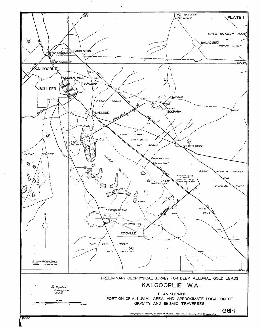
/ " / 'v' //
/ /
-----./------
?I~~ AI" FOULe , ... /Iomesu-d '.....,pLATE I
'\ \
\ • \
\ '\
'\ .... \/ ......
, , " ,
SCRUB SALTBUSH
AND
" < ". BALAGUNDI
l\, > MEDIUM TIMBER / '--<.' / \
/ \ / "-
/ ~ ----L ___ \...,,-/'" - ___ _ ./
1~----~~----~~~~~----~~--------------------------------~~~------------------------------3O·~'
I ,-.1--.----'
/1 I I , I \ ..:.".\1 .... ~ 11"\
//1\ / II
",/ 1\ ",/' , \
,." I \ LlOI-IT TIMBER I •
.... .;. \ "" .... /... \
.. ~ .. , I \ \ ~ /: I
I).. { I
\
/ ~. I. ~ / ~ .... , I '~, ~:::; \
/ ~ ..... \ 0' • .'- I':", \ ",'< I. , \ :~,'? ~ . .. I", ~ \ .... f.." ': ...... )
/ ......... ,."j' / ,.,,"" /
...... / / -- /
/ /
// ! I
/ N
A.t:'o""".nd~ d-• .1/-' 0 R_ ---
[PSS
71wo1M -- --
J} tL.,;;-~......r. G=l'h,!/&,'cI$l :JI·$·49
.... '"
~-
,.,...-----
THIN
\
'. '.
..........
" AF' S;~· ~I~ ......,,, =1,\\'. '- j'-" .........
FEYSVILLE'l ......
) I
DAMO
\ \
...... \
~
\ \ )
/
/
/ /
/
/
/ /
I
\ LIGHT \\
------;-- ------TIMBER
AND \ 50
SAL T13USN
\.r----t-----l:=:::;----"'----"--..... -----]~ PRELIMINARY GEOPHYSICAL SURVEY FOR DEEP ALLUVIAL GOLD LEADS
KALGOORLIE W.A. PLAN SHOWING
PORTION OF ALLUVIAL AREA AND APPROXIMATE LOCATION OF GRAVITY AND SEISMIC TRAVERSES.
GeophYSICB/ Secl,on, BLlrt!!Mi)L/ 01' Minorsl ROSQUrC08 (le%gy t9nd GeophyQic.s. G61-1

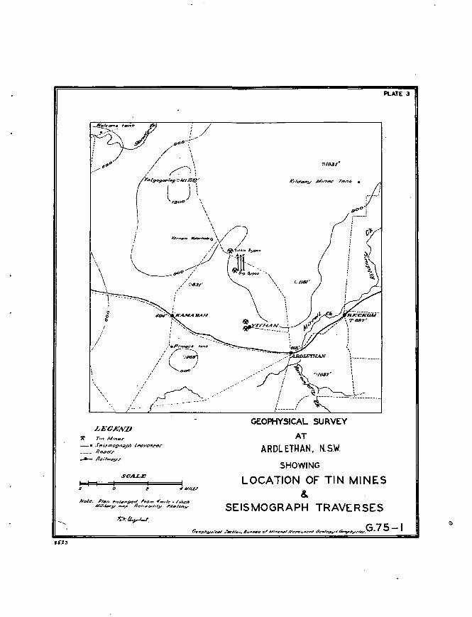
, , , ,
LECEND 'X" Tin AlIn~1J'
-II fei.rmogPeI,Ph Ip,[email protected]" ____ /lo8dr
____ /lc9ill'VrlJlYJ"
SCALE
I I e o e
Nole. PI4In rnI8,.~d "0'" .,_,/~ ... /"ch Ni/;/w;oy _p /l6hlo,ld,y J"..t'/e'hy
GEOPHYSICAL SURVEY
AT
ARDL ETHAN. N.S.W.
SHOWING
PLATE 3
LOCATION OF TIN MINES &
SEISMOGRAPH TRAVERSES
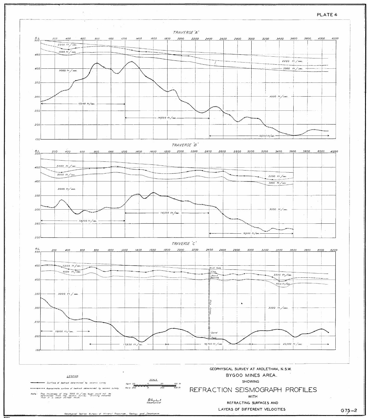


LEGEND
~ ALLUMUV RECENT
~::::n ETC.} D£YOMNI
~ SJt4U LtIoESTONE Eft.}
[2]""" SILURIAN
~SLA7F ORDOVICIAN
0UJJPRtJI'HtRE - _ROoIDS. m«ltS _.- _ /IOUIIJARES
_R.(JLJtl4T
t""-'O APPROXJ1rIATE IJOI.NIJMlr OF AREA LEASED 6Y ~ ~ ALI.LM4LS LTD. FOR /JIl£DGIiG
· SKETCH SECTION AA
SCALE IN MILES,
o . 3
GEOPHYSICAL SURVEY Al WElUIlGroN. N S. W
SEISMIC. REFRACnON SURVEY ON
ALLUVIAL GOLD DREDGING LEASE.S
LOCALITY PLAN SHOWNG GEOtOGy, PORTION OF AREA L£ASED
BY WELLINGTON ALUMAL$ LTD. .. ARCA IN WHICH SE/S1rIlC
SlRVEY WAS ItIADC NC11F -GEO<DGT CDPIED FPOM PUN