Embed Size (px)
Citation preview
This straightforward 3-D display algorithm traverses voxels slice by slice toproject each voxel on the screen. No surface detection or z-buffer is needed.
Back to-Front Display of Voxel BasedObjects
Gideon Frieder
University of Michigan
Dan Gordon
University of Cincinnati
R. Anthony Reynolds
University of Pennsylvania
With the advent of medical imaging devices such ascomputed tomography, positron emission tomography,single photon emission computed tomography, magneticresonance imaging, and ultrasound scanners, methods arewidely available for capturing the shape and other proper-ties of real objects (human organs) directly in machine-readable form. One way of presenting the information forreview is to display the organ as a three-dimensional ob-ject, using established computer graphics techniques forcreating images by projection onto a two-dimensional sur-face such as the screen of a raster-scan device.Many approaches to 3-D display are available; both
hardware and software methods have been reviewedrecently. 1,2 Most methods require some preprocessing ofthe input to reduce data and to provide object representa-tions better suited to the available display algorithms. Oneapproach that has been applied widely to medical applica-tions uses an automatic boundary-detection algorithm toextract the surface of a single connected object from thedata.3-5 A second approach extracts a set of 1-D primi-tives (contours) describing the boundaries of the object ona slice-by-slice basis. Surface representations can be ob-tained from the contours directly, or indirectly by tiling orby spline techniques.6-14 A third approach retains 3-Dvoxels (cubes or rectangular parallelepipeds) as primitivesbut achieves data compression through octree encoding,which provides an efficient object representation. 15,16
While surface representations achieve extensive datareduction, surface formation is time-consuming. In addi-tion it is not possible to explore the interior of the objectinteractively, or generate cut-away views, without form-ing a new surface. The back-to-front (BTF) methodpresented in this article displays entire solid objects com-posed of voxels without extracting the object surface firstand with a minimum of preprocessing.
Data collection and the cuberille model
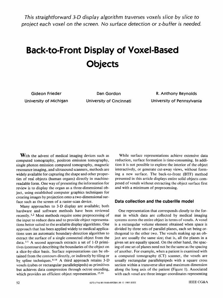
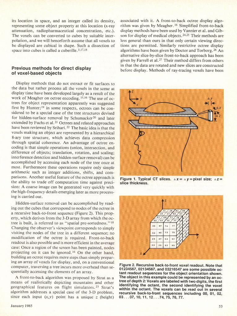
One representation that corresponds closely to the for-mat in which data are collected by medical imagingsystems stores the entire object in terms of voxels. A voxelis a rectangular volume element obtained when space isdivided by three sets of parallel planes, each set being or-thogonal to the other two. The voxels making up an ob-ject are usually the same size; that is, all the planes in agiven set are equally spaced. On the other hand, the spac-ing of one set of planes need not be the same as the spacingof another. For example, when a patient is examined witha computed tomography (CT) scanner, the voxels areusually rectangular parallelepipeds with a square crosssection within a transverse slice and maximum dimensionalong the long axis of the patient (Figure 1). Associatedwith each voxel are three integer coordinates representing
0272-1716/85/0100-0052$01.00 0 1985 IEEE IEEE CG&A52
its location in space, and an integer called its density,representing some object property at this location (x-rayattenuation, radiopharmaceutical concentration, etc.).The voxels can be converted to cubes by suitable inter-polation, and we will henceforth assume that all voxels tobe displayed are cubical in shape. Such a dissection ofspace into cubes is called a cuberille.3,17,18
Previous methods for direct displayof voxel-based objects
Display methods that do not extract or fit surfaces tothe data but rather process all the voxels in the scene atdisplay time have been developed largely as a result of thework of Meagher on octree encoding. 15,16 The use of oc-trees for object representation apparently was suggestedfirst by Hunter; 19 in some respects, octrees can be con-sidered to be a special case of the tree structures devisedfor hidden-surface removal by Schumacker20 and laterextended by Fuchs et al. 21 Octrees and related approacheshave been reviewed by Srihari.22 The basic idea is that thevoxels making an object are represented by a hierarchical8-ary tree structure, which achieves data compressionthrough spatial coherence. An advantage of octree en-coding is that simple operations (union, intersection, anddifference of objects; translation, rotation, and scaling;interference detection and hidden-surface removal) can beaccomplished by accessing each node of the tree once atmost. Furthermore these operations require only simplearithmetic such as integer additions, shifts, and com-parisons. Another useful feature of the octree approach isthe ability to trade off computation time against preci-sion: A coarse image can be generated very quickly withthe high-frequency details emerging later as more process-ing is carried out.
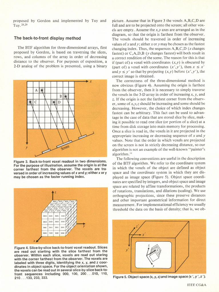
Hidden-surface removal can be accomplished by read-ing out the cubes that correspond to nodes of the octree ina recursive back-to-front sequence (Figure 2). This prop-erty, which derives from the 3-D array from which the oc-tree is built, is referred to as "spatial pre-sortedness." 18Changing the observer's viewpoint corresponds to simplyvisiting the nodes of the tree in a different sequence; nomodification of the octree is required. Front-to-backreadout is also possible and is more efficient in the averagecase: Once a region of the screen has been painted, nodesprojecting on it can be ignored. 16 On the other hand,building an octree requires more steps than simply prepar-ing an array of voxels for display, and, on a conventionalcomputer, traversing a tree incurs more overhead than se-quentially accessing the elements of an array.A front-to-back algorithm was proposed by Strat as a
means of realistically depicting mountains and othergeographical features on flight simulators.23 Strat'salgorithm addresses a special case of the 3-D problem,since each input (x,y) point has a unique z (height)
associated with it. A front-to-back octree display algo-rithm was given by Meagher. 16 Simplified front-to-backdisplay methods have been used by Vannier et al. and Gib-son for display of medical objects. 24'25 Their methods areless general than ours in that only certain viewing direc-tions are permitted. Similarly restrictive octree displayalgorithms have been given by Doctor and Torborg.26 Analternative slice-by-slice front-to-back approach has beengiven by Farrell et al. 27 Their method differs from othersin that the data are rotated and new slices are constructedbefore display. Methods of ray-tracing voxels have been
Figure 1. Typical CT slices. A x = A y = pixel size; A Z =slice thickness.
Figure 2. Recursive back-to-front voxel readout. Note that01234567, 02134567, and 03216547 are some possible oc-tant readout sequences for the object orientation shown.The object in this example could be represented by an oc-tree of depth 2: Voxels are labeled with two digits, the firstidentifying the octant, the second identifying the voxelwithin the octant. The voxels can be read out in severalrecursive back-to-front sequences including 00, 01, 02,03... .07,10,11, 12... .74, 75, 76, 77.
January 1985 53
proposed by Gordon and implemented by Tuy andTuy. 28,29
The back-to-front display method
The BTF algorithm for three-dimensional arrays, firstproposed by Gordon, is based on traversing the slices,rows, and columns of the array in order of decreasingdistance to the observer. For purposes of exposition, a2-D analog of the problem is presented, using a binary
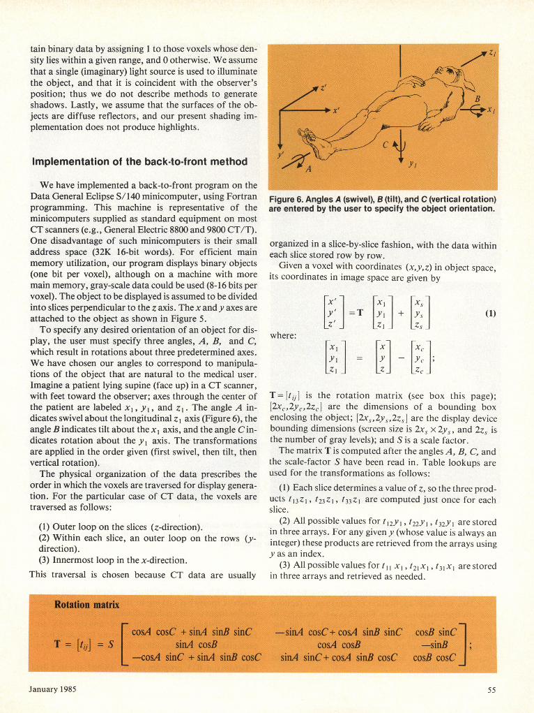
Figure 3. Back-to-front voxel readout in two dimensions.For the purpose of illustration, assume the origin is at thecorner farthest from the observer. The voxels are tra-versed in order of increasing values of x and y; either x or ymay be chosen as the faster running index.
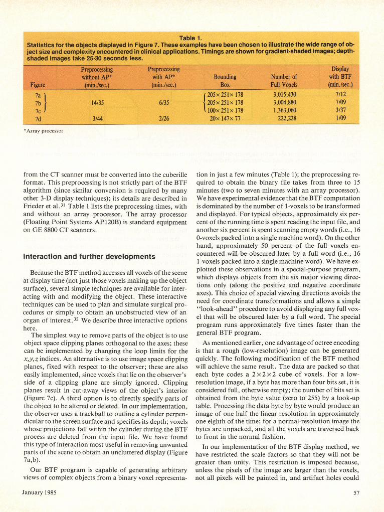
Figure 4. Slice-by-slice back-to-front voxel readout. Slicesare read out starting with the slice farthest from theobserver. Within each slice, voxels are read out staringwith the corner farthest from the observer. The voxels arelabeled with three digits, identifying the x, y, and z coor-dinates in object space. For the object orientation shown,the voxels can be read out in several slice-by-slice back-to-front sequences including 000, 100, 200 010, 110,210 .. 133,233,333.
picture. Assume that in Figure 3 the voxels A,B,C,D arefull and are to be projected onto the screen; all other vox-els are empty. Assume the x,y axes are arranged as in thediagram, so that the origin is farthest from the observer.The voxels should be traversed in order of increasingvalues ofx and y; either x or y may be chosen as the fastestchanging index. Thus, the sequences A,B,C,D (x changesfastest) or C,A,D,B (y changes fastest) will both result ina correct rendition of the scene. The reason for this is thatif (part of) a voxel with coordinates (x,y) is obscured by(part of) a voxel with coordinates (x',y'), then x c x'andy c y' so that by projecting (x,y) before (x',y'), thecorrect image is obtained.The correctness of the three-dimensional method is
now obvious (Figure 4). Assuming the origin is farthestfrom the observer, then it is necessary to simply traversethe voxels in the 3-D array in order of increasing x, y, andz. If the origin is not the farthest corner from the observ-er, some of x,y,z should be increasing and some should bedecreasing. However, the choice of which index changesfastest can be arbitrary. This fact can be used to advan-tage in the case of data that are stored slice by slice, mak-ing it possible to read one slice (or portion of a slice) at atime from disk storage into main memory for processing.Once a slice is read in, the voxels in it are projected in theappropriate increasing or decreasing sequence of x and yvalues. Note that the order in which voxels are projectedon the screen is not in strictly decreasing distance, so ouralgorithm is not an example of the well-known "painter'salgorithm. "The following conventions are useful in the description
of the BTF algorithm. We refer to the coordinate systemin which the voxels of the object are defined as objectspace and the coordinate system in which they are dis-played as image space (Figure 5). Object space coordi-nates are specified by integers, and object space and imagespace are related by affine transformations, the productsof rotations, translations, and dilations (scaling). We useorthographic projections, since these preserve distancesand other important geometrical information for directmeasurement. For implementational efficiency we usuallythreshold the data on the basis of density; that is, we ob-
Figure 5. Object space (x, y, z) and image space (x ',y ',z ').
IEEE CG&A
tain binary data by assigning 1 to those voxels whose den-sity lies within a given range, and 0 otherwise. We assumethat a single (imaginary) light source is used to illuminatethe object, and that it is coincident with the observer'sposition; thus we do not describe methods to generateshadows. Lastly, we assume that the surfaces of the ob-jects are diffuse reflectors, and our present shading im-plementation does not produce highlights.
Implementation of the back-to-front method
We have implemented a back-to-front program on theData General Eclipse S/140 minicomputer, using Fortranprogramming. This machine is representative of theminicomputers supplied as standard equipment on mostCT scanners (e.g., General Electric 8800 and 9800 CT/T).One disadvantage of such minicomputers is their smalladdress space (32K 16-bit words). For efficient mainmemory utilization, our program displays binary objects(one bit per voxel), although on a machine with moremain memory, gray-scale data could be used (8-16 bits pervoxel). The object to be displayed is assumed to be dividedinto slices perpendicular to the z axis. The x andy axes areattached to the object as shown in Figure 5.To specify any desired orientation of an object for dis-
play, the user must specify three angles, A, B, and C,which result in rotations about three predetermined axes.We have chosen our angles to correspond to manipula-tions of the object that are natural to the medical user.Imagine a patient lying supine (face up) in a CT scanner,with feet toward the observer; axes through the center ofthe patient are labeled x,, yi, and z,. The angle A in-dicates swivel about the longitudinal z I axis (Figure 6), theangle B indicates tilt about the xl axis, and the angle C in-dicates rotation about the Yi axis. The transformationsare applied in the order given (first swivel, then tilt, thenvertical rotation).The physical organization of the data prescribes the
order in which the voxels are traversed for display genera-tion. For the particular case of CT data, the voxels aretraversed as follows:
(1) Outer loop on the slices (z-direction).(2) Within each slice, an outer loop on the rows (y-direction).(3) Innermost loop in the x-direction.
This traversal is chosen because CT data are usually
Figure 6. Angles A (swivel), B (tilt), and C (vertical rotation)are entered by the user to specify the object orientation.
organized in a slice-by-slice fashion, with the data withineach slice stored row by row.
Given a voxel with coordinates (x,y,z) in object space,its coordinates in image space are given by
(1)
where:
I = IYILz Lz LZcc
T= ftij] is the rotation matrix (see box this page);[2x,,2y,,2z,] are the dimensions of a bounding boxenclosing the object; [2x,,2y,,2z,] are the display devicebounding dimensions (screen size is 2x5 x 2yS, and 2z, isthe number of gray levels); and S is a scale factor.The matrix T is computed after the angles A, B, C, and
the scale-factor S have been read in. Table lookups areused for the transformations as follows:
(1) Each slice determines a value of z, so the three prod-ucts t13ZI, t23ZI, t33ZI are computed just once for eachslice.
(2) All possible values for t12y I, t22Y, t32yI are storedin three arrays. For any given y (whose value is always aninteger) these products are retrieved from the arrays usingy as an index.
(3) All possible values fortII x , t2X, t31xi are storedin three arrays and retrieved as needed.
January 1985 55
:= T : + s
zI zi Zs

Figure 7. Three views of a human spine and one of a human skull: User outlines material to be removed with a trackball(a); unobscured view with unwanted material removed (b); part of the same spine cut open with object space clippingplane to reveal internal structure (c); and a skull of another patient (d).
In a typical setting, the bounding box could be 256 x256 x 256, and each application of Equation 1 requiresnine multiplications. This would have resulted in9x224 = 1.51 x 10⁸ multiplications instead of the 9x256 = 2304 required by our use of look-up tables. A fur-ther saving is achieved by computing the sums t12 YI +t13ZI, t22 YI + t23 zI and t32 yI + t33 ZI just once foreach row of a slice.
56
The BTF program produces a depth-shaded image,which is somewhat lacking in fine detail. This image isused as input to our gradient-shading method, which usesboth the distance from the light source and the object sur-face orientation to compute the intensity to be assigned toeach pixel. 30 We used gradient shading to produce the im-ages shown in Figure 7.
Before our BTF program can be applied, the slice data
IEEE CG&A
*Array processor
from the CT scanner must be converted into the cuberilleformat. This preprocessing is not strictly part of the BTFalgorithm (since similar conversion is required by manyother 3-D display techniques); its details are described inFrieder et al.31 Table I lists the preprocessing times, withand without an array processor. The array processor(Floating Point Systems AP120B) is standard equipmenton GE 8800 CT scanners.
Interaction and further developments
Because the BTF method accesses all voxels of the sceneat display time (not just those voxels making up the objectsurface), several simple techniques are available for inter-acting with and modifying the object. These interactivetechniques can be used to plan and simulate surgical pro-cedures or simply to obtain an unobstructed view of anorgan of interest.32 We describe three interactive optionshere.
The simplest way to remove parts of the object is to useobject space clipping planes orthogonal to the axes; thesecan be implemented by changing the loop limits for thex,y,z indices. An alternative is to use image space clippingplanes, fixed with respect to the observer; these are alsoeasily implemented, since voxels that lie on the observer'sside of a clipping plane are simply ignored. Clippingplanes result in cut-away views of the object's interior(Figure 7c). A third option is to directly specify parts ofthe object to be altered or deleted. In our implementation,the observer uses a trackball to outline a cylinder perpen-dicular to the screen surface and specifies its depth; voxelswhose projections fall within the cylinder during the BTFprocess are deleted from the input file. We have foundthis type of interaction most useful in removing unwantedparts of the scene to obtain an uncluttered display (Figure7a,b).Our BTF program is capable of generating arbitrary
views of complex objects from a binary voxel representa-
tion in just a few minutes (Table 1); the preprocessing re-quired to obtain the binary file takes from three to 15minutes (two to seven minutes with an array processor).We have experimental evidence that the BTF computationis dominated by the number of I -voxels to be transformedand displayed. For typical objects, approximately six per-cent of the running time is spent reading the input file, andanother six percent is spent scanning empty words (i.e., 160-voxels packed into a single machine word). On the otherhand, approximately 50 percent of the full voxels en-countered will be obscured later by a full word (i.e., 161-voxels packed into a single machine word). We have ex-ploited these observations in a special-purpose program,which displays objects from the six major viewing direc-tions only (along the positive and negative coordinateaxes). This choice of special viewing directions avoids theneed for coordinate transformations and allows a simple"look-ahead" procedure to avoid displaying any full vox-el that will be obscured later by a full word. The specialprogram runs approximately five times faster than thegeneral BTF program.As mentioned earlier, one advantage of octree encoding
is that a rough (low-resolution) image can be generatedquickly. The following modification of the BTF methodwill achieve the same result. The data are packed so thateach byte codes a 2 x 2 x 2 cube of voxels. For a low-resolution image, if a byte has more than four bits set, it isconsidered full, otherwise empty; the number of bits set isobtained from the byte value (zero to 255) by a look-uptable. Processing the data byte by byte would produce animage of one half the linear resolution in approximatelyone eighth of the time; for a normal-resolution image thebytes are unpacked, and all the voxels are traversed backto front in the normal fashion.
In our implementation of the BTF display method, wehave restricted the scale factors so that they will not begreater than unity. This restriction is imposed because,unless the pixels of the image are larger than the voxels,not all pixels will be painted in, and artifact holes could
January 1985 57
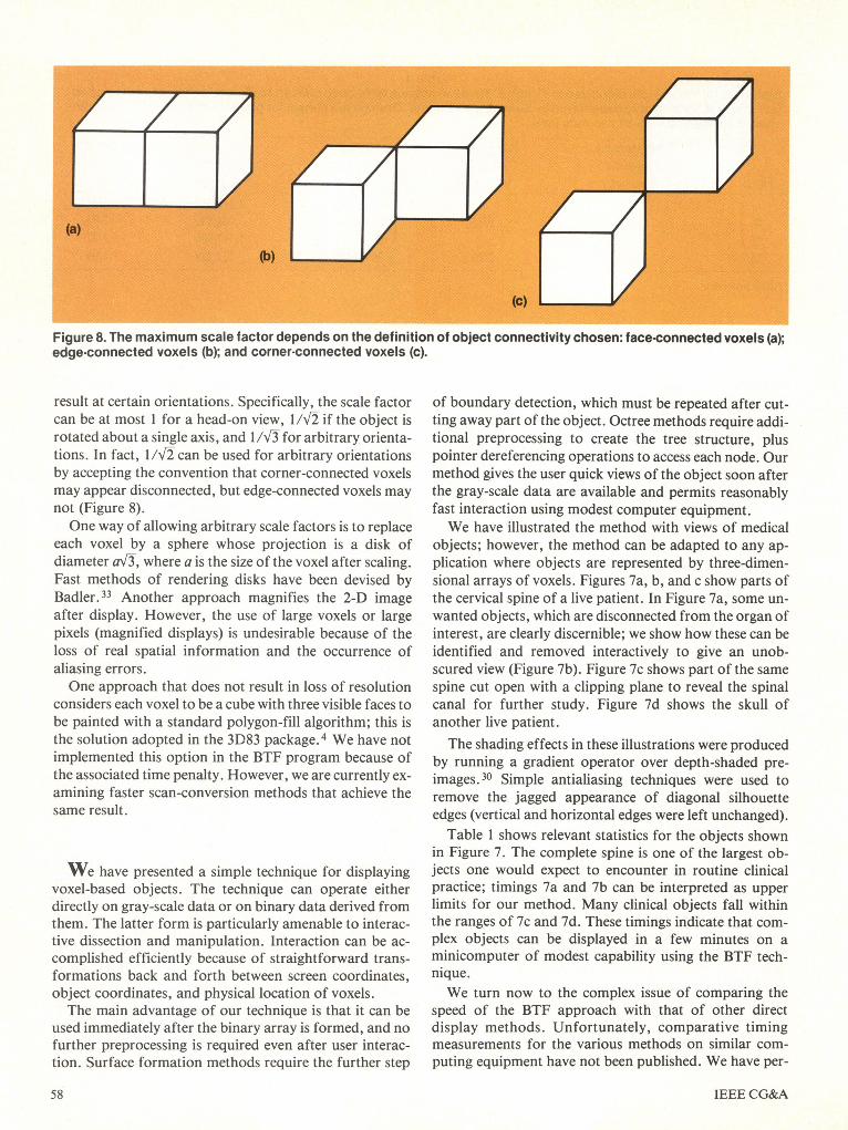
Figure 8. The maximum scale factor depends on the definition of object connectivity chosen: face-connected voxels (a);edge-connected voxels (b); and corner-connected voxels (c).
result at certain orientations. Specifically, the scale factorcan be at most I for a head-on view, 1V/2 if the object isrotated about a single axis, and 1/Vr3 for arbitrary orienta-tions. In fact, I/v2 can be used for arbitrary orientationsby accepting the convention that corner-connected voxelsmay appear disconnected, but edge-connected voxels maynot (Figure 8).One way of allowing arbitrary scale factors is to replace
each voxel by a sphere whose projection is a disk ofdiameter a\3, where a is the size of the voxel after scaling.Fast methods of rendering disks have been devised byBadler.33 Another approach magnifies the 2-D imageafter display. However, the use of large voxels or largepixels (magnified displays) is undesirable because of theloss of real spatial information and the occurrence ofaliasing errors.One approach that does not result in loss of resolution
considers each voxel to be a cube with three visible faces tobe painted with a standard polygon-fill algorithm; this isthe solution adopted in the 3D83 package.4 We have notimplemented this option in the BTF program because ofthe associated time penalty. However, we are currently ex-amining faster scan-conversion methods that achieve thesame result.
We have presented a simple technique for displayingvoxel-based objects. The technique can operate eitherdirectly on gray-scale data or on binary data derived fromthem. The latter form is particularly amenable to interac-tive dissection and manipulation. Interaction can be ac-complished efficiently because of straightforward trans-formations back and forth between screen coordinates,object coordinates, and physical location of voxels.The main advantage of our technique is that it can be
used immediately after the binary array is formed, and nofurther preprocessing is required even after user interac-tion. Surface formation methods require the further step
of boundary detection, which must be repeated after cut-ting away part of the object. Octree methods require addi-tional preprocessing to create the tree structure, pluspointer dereferencing operations to access each node. Ourmethod gives the user quick views of the object soon afterthe gray-scale data are available and permits reasonablyfast interaction using modest computer equipment.We have illustrated the method with views of medical
objects; however, the method can be adapted to any ap-plication where objects are represented by three-dimen-sional arrays of voxels. Figures 7a, b, and c show parts ofthe cervical spine of a live patient. In Figure 7a, some un-wanted objects, which are disconnected from the organ ofinterest, are clearly discernible; we show how these can beidentified and removed interactively to give an unob-scured view (Figure 7b). Figure 7c shows part of the samespine cut open with a clipping plane to reveal the spinalcanal for further study. Figure 7d shows the skull ofanother live patient.The shading effects in these illustrations were produced
by running a gradient operator over depth-shaded pre-images.30 Simple antialiasing techniques were used toremove the jagged appearance of diagonal silhouetteedges (vertical and horizontal edges were left unchanged).Table I shows relevant statistics for the objects shown
in Figure 7. The complete spine is one of the largest ob-jects one would expect to encounter in routine clinicalpractice; timings 7a and 7b can be interpreted as upperlimits for our method. Many clinical objects fall withinthe ranges of 7c and 7d. These timings indicate that com-plex objects can be displayed in a few minutes on aminicomputer of modest capability using the BTF tech-nique.We turn now to the complex issue of comparing the
speed of the BTF approach with that of other directdisplay methods. Unfortunately, comparative timingmeasurements for the various methods on similar com-puting equipment have not been published. We have per-
IEEE CG&A58
formed experiments that indicate that slice-by-slice BTF isfaster than recursive BTF (Figure 2) or ray tracing whenimplemented on a conventional minicomputer. Compar-ing slice-by-slice BTF with a front-to-back method-using, for example, octrees-is an interesting subject forfurther research. The strength of the BTF method lies inits simplicity. The advantage of the front-to-back methodis that once a region of the screen has been painted, subse-quent voxels in the object (or nodes of the octree) thatproject on it need not be processed; the disadvantage isthat a complex data structure is required to efficientlydetermine which regions of the screen have already beenpainted.
On the other hand, when special computer architec-tures are devised, many problematic issues can be avoidedboth with octree encoding and with BTF. A high-per-formance octree display system is available from PhoenixData Systems, Inc., Albany, New York. A small hard-ware prototype of a recursive BTF system, the Voxel Pro-
cessor, is now operational in the GRASP Laboratory,University of Pennsylvania, and achieves display rates of16 frames per second. 34,35 U
AcknowledgmentsWe wish to acknowledge many helpful discussions with
L. S. Chen, G. T. Herman, S. S. Trivedi, and J. K. Udupaof the Medical Image Processing Group. We wish tothank D. J. Meagher, M. W. Vannier, and the anony-mous referees for their helpful comments. Thanks arealso due to G. T. Herman for the patient data used in Fig-ure 7 and to D. W. Ro and S. Strommer for photography.Part of the work was carried out using the Medical ImageProcessing Group computing facility. This work was sup-ported by NIH grant HL28438. The GRASP Laboratoryis supported by grants ARO DAA6-29-84-K-0061,AFOSR 82-NM-299, NSF MCS-8219196-CER, NSFMCS 82-07294, AVRO DAABO7-84-K-FO77, and NIH1-RO1-HL-29985-01.
References
1. R. A. Reynolds, "Some Architectures for Real-TimeDisplay of Three-Dimensional Objects: A ComparativeSurvey," tech. report MIPG84, Dept. of Radiology, Univ.of Pennsylvania, Oct. 1983.
2. J. K. Udupa, "Display of 3D Information in Discrete 3DScenes Produced by Computerized Tomography," Proc.IEEE, Vol. 71, No. 3, Mar. 1983, pp. 420-431.
3. G. T. Herman and J. K. Udupa, "Display of 3-D DigitalImages: Computational Foundations and Medical Applica-tions," IEEE Computer Graphics and Applications, Vol. 3,No. 5, Aug. 1983, pp. 39-46.
4. L. S. Chen, G. T. Herman, C. M. Meyer, R. A. Reynolds,and J. K. Udupa, "3D83-An Easy-to-Use SoftwarePackage for Three-Dimensional Display from ComputedTomograms," IEEE Computer Soc. Int'l Symp. MedicalImages and Icons, Arlington, Va., July 1984, pp. 309-316.
5. E. Artzy, G. Frieder, and G. T. Herman, "The Theory,Design, Implementation and Evaluation of a Three-Dimensional Surface Detection Algorithm," ComputerGraphics and Image Processing, Vol. 15, Jan. 1981, pp.1-24.
6. J. K. Udupa, "Interactive Segmentation and Boundary Sur-face Formation for 3D Digital Images," Computer Graph-ics and Image Processing, Vol. 18, 1982, pp. 213-235.
7. E. Keppel, "Approximating Complex Surfaces byTriangulation of Contour Lines," IBM J. Research andDevelopment, Vol. 19, Jan. 1975, pp. 2-1 1.
8. J. C. Mazziotta and K. H. Huang, "THREAD (Three-Dimensional Reconstruction and Display) with BiomedicalApplications in Neuron Ultrastructure and ComputerizedTomography, "AFIPS Conf. Proc., Vol. 45, 1976 NCC, pp.241-250.
9. H. N. Christiansen and T. W. Sederberg, "Conversion ofComplex Contour Line Definitions into Polygonal ElementMosaics," Computer Graphics (Proc. Siggraph 78), Vol. 12,No. 3, Aug. 1978, pp. 187-192.
10. D. L. McShan, A. Silverman, D. M. Lanza, L. E. Rein-stein, and A. S. Glicksman, "A Computerized Three-Di-mensional Treatment Planning System Utilizing InteractiveColor Graphics," British J. Radiology, Vol. 52, 1979, pp.478-481.
11. L. T. Cook, S. J. Dwyer, S. Batnitsky, and K. R. Lee, "AThree-Dimensional Display System for Diagnostic ImagingApplications," IEEE Computer Graphics and Applica-tions, Vol. 3, No. 5, Aug. 1983, pp. 13-19.
12. D. S. Schlusselberg, W. K. Smith, M. H. Lewis, B. G.Culter, and D. J. Woodward, "A General System for Com-puter Based Acquisition, Analysis and Display of MedicalImage Data," Proc. ACM Ann. Meeting, Oct. 1982, pp.18-25.
13. H. Fuchs, G. D. Abram, and E. D. Grant, "Near Real-Time Shaded Display of Rigid Objects," Computer Graph-ics (Proc. Siggraph 83), Vol. 17, No. 3, July 1983, pp. 65-72.
January 1985 59
14. A. Sunguroff and D. Greenberg, "Computer GeneratedImages for Medical Applications," Computer Graphics(Proc. Siggraph 78), Vol. 12, No. 3, Aug. 1978, pp. 196-202.
15. D. Meagher, "Geometric Modelling Using Octree En-coding," Computer Graphics and Image Processing, Vol.19, 1982, pp. 129-147.
16. D. Meagher, "The Octree Encoding Method for EfficientSolid Modelling," PhD dissertation, Rensselaer Polytech-nic Institute, Aug. 1982.
17. G. T. Herman and H. K. Liu, "Three-Dimensional Displayof Human Organs from Computed Tomograms," Com-puter Graphics and Image Processing, Vol. 9, Jan. 1979,pp. 1-21.
18. G. T. Herman, R. A. Reynolds, and J. K. Udupa, "Com-puter Techniques for the Representation of Three-Dimensional Data on a Two-Dimensional Display," Proc.SPIE, Vol. 367, 1982, pp. 3-14.
19. G. M. Hunter, "Efficient Computation and Data Struc-tures for Graphics," PhD dissertation, Dept. of ElectricalEng. and Comp. Sci., Princeton Univ., June 1978.
20. 1. E. Sutherland, R. F. Sproull, and R. A. Schumacker, "ACharacterization of Ten Hidden Surface Algorithms,"Computing Surveys, Vol. 6, No. 1, Mar. 1974.
21. H. Fuchs, Z. M. Kedem, and B. F. Naylor, "On VisibleSurface Generation by A Priori Tree Structures," Com-puter Graphics (Proc. Siggraph 80), Vol. 14, No. 3, 1980,pp. 124-133.
22. S. N. Srihari, "Representation of Three-DimensionalDigital Images," Computing Surveys, Vol. 13, No. 4, 1981,pp. 399-424.
23. T. M. Strat, "Application of Data Flow Computation tothe Shaded Image Problem," working paper 163, A. 1.Laboratory, MIT, Cambridge, Mass., May 1978.
24. M. W. Vannier, J. L. Marsh, and J. 0. Warren, "ThreeDimensional Computer Graphics for Craniofacial SurgicalPlanning and Evaluation," Computer Graphics (Proc. Sig-graph 83), Vol. 17, No. 3, July 1983, pp. 263-273.
25. C. J. Gibson, "A New Method for the Three-DimensionalDisplay of Tomographic Images," Physics in Medicine andBiology, Vol. 28, No. 10, 1983, pp. 1153-1157.
26. L. J. Doctor and J. G. Torborg, "Display Techniques forOctree-Encoded Objects," IEEE Computer Graphics andApplications, Vol. 1, No. 3, July 1981, pp. 29-38.
27. E. J. Farrell, R. Zappulla, and W. C. Yang, "Color 3-D Im-aging of Normal and Pathologic Intracranial Structures,"IEEE Computer Graphics and Applications, Vol. 4, No. 9,Sept. 1984, pp. 5-19.
28. D. Gordon, "Boundary Detection and Display: Some In-formal Research Notes," typed notes, Dept. of Comp.Studies, Univ. of Haifa, Israel, July 1982.
29. H. K. Tuy and L. T. Tuy, "Direct 2-D Display of 3-D Ob-jects," IEEE Computer Graphics and Applications, Vol. 4,No. 10, Nov. 1984, pp. 29-33.
30. D. Gordon and R. A. Reynolds, "Image Space Shading ofThree-Dimensional Objects," tech. report MIPG85, Dept.of Radiology, Univ. of Pennsylvania, Nov. 1983. (To bepublished in Computer Vision, Graphics and Image Pro-cessing. )
31. G. Frieder, D. Gordon, and R. A. Reynolds, "Back-to-Front Display of Voxel-Based Objects," tech. reportMIPG89, Dept. of Radiology, Univ. of Pennsylvania, Aug.1984.
32. L. J. Brewster, S. S. Trivedi, H. K. Tuy, and J. K. Udupa,"Interactive Surgical Planning," IEEE Computer Graphicsand Applications, Vol. 4, No. 3, Mar. 1984, pp. 31-40.
33. N. I. Badler, "Disk Generators for a Raster DisplayDevice, " Computer Graphics and Image Processing, Vol. 6,No. 6, Dec. 1977, pp. 589-593.
34. S. M. Goldwasser and R. A. Reynolds, "An Architecturefor the Real-Time Display and Manipulation of Three-Dimensional Objects," Proc. Int'l Conf. Parallel Process-ing, Bellaire, Mich., Aug. 1983, pp. 269-274.
35. S. M. Goldwasser, "A Generalized Object Display Pro-cessor Architecture," IEEE Computer Graphics and Ap-plications, Vol. 4, No. 10, Oct. 1984, pp. 43-55.
Gideon Frieder is currently professor of elec-trical engineering and computer science at theUniversity of Michigan, where he also servesas chairman of the Division of ComputerScience and Engineering. Prior to that he wasprofessor of computer science at the StateUniversity of New York in Buffalo, a staffmember of IBM Scientific Center at Haifa,Israel, and head of Computer Science in theIsraeli Department of Defense.
Frieder is a member of ACM, where he served as national lec-turer and a board member of Sigmicro and is a member of theIEEE Computer Society and TC-Micro. His interest in publica-tion spans the areas of computer architecture, micro program-ming, operating system design, medically motivated algorithmsfor storage management in graphics, and robotic vision.
Dan Gordon is a visiting associate professorof computer science at the University of Cin-cinnati, where he taught from 1977 through1979. He is on leave from the Department ofComputer Studies at the University of Haifa,Israel. His current research interests include
- J design and analysis of algorithms, computa-tional geometry, computer graphics, VLSI,and computerized tomography.Gordon received his BSc and MSc degrees
in mathematics from the Hebrew University in Jerusalem, andhis DSc from the Technion-Israel Institute of Technology. He isa member of the European Association for Theoretical Com-puter Science.
R. Anthony Reynolds is with the General Ro-botics and Active Sensory Processing groupat the University of Pennsylvania. He hopesto graduate with a PhD in computer and in-formation science in May 1985. From 1976 to1980 he was a physicist with the Cancer Con-trol Agency of British Columbia, Canada,working with computers in medical imagingand radiation therapy planning. He is cur-rently working on 3-D display of medical ob-
jects, using hardware and software techniques.Reynolds obtained a BA in physics from Trinity College,
Dublin, in 1971. In 1973 he obtained an MSc in physics from theUniversity of Alberta, Edmonton. He is a member of the Cana-dian Medical and Biological Engineering Society, the AmericanAssociation of Physicists in Medicine, the ACM, and the IEEE.
Questions about this article may be addressed to R. AnthonyReynolds, Computer & Information Science, Moore School ofElec. Engineering, Univ. of Pa., Philadelphia, PA 19104.
60