Embed Size (px)
Citation preview
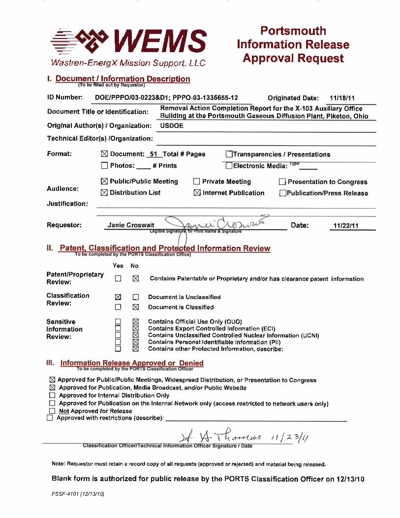
Ms. Maria Galanti Site Coordinator
Department of Energy
Portsmouth/Paducah Project Office 1017 Majestic Drive, Suite 200
Lexington, Kentucky 40513 (859) 219-4000
NOV f 8}.~11
Ohio Environmental Protection Agency Southeast District Office 2195 Front Street Logan, Ohio 43138
Dear Ms. Galanti:
PPPO-03-1335655-12
REMOVAL ACTION COMPLETION REPORT FOR THE X-I03 AUXILIARY OFFICE BUILDING AT THE PORTSMOUTH GASEOUS DIFFUSION PLANT, PIKETON, OHIO
Enclosed for your review and concurrence, please find the Removal Action Completion Report for the X-J 03 Auxiliary Office Building at the Portsmouth Gaseous Diffusion Plant, Piketon, Ohio (DOE/PPPOI03-0223&Dl). This document was prepared in accordance with the Director's Final Findings and Orders for Removal Action and Remedial Investigation and Feasibility Study and Remedial Design and Remedial Actionfor the Portsmouth Gaseous Diffusion Plant (Decontamination and Decommissioning Project), as amended on September 12, 2011.
This Removal Action Completion Report documents completion of the Phase I and Phase II activities for the X-l03 Building Comprehensive Environmental Response, Compensation, and Liability Act (CERCLA) non-time-critical removal action, as described in the Removal Action Work Plan for the X-J 03 Auxiliary Office Building at the Portsmouth Gaseous Diffusion Plant, Piketon, Ohio (RA WP). Removal action alternatives for the X-l03 Building were evaluated in the Engineering Evaluation/Cost Analysis for Group J Buildings X-J 03, X-334, and X-344B at the Portsmouth Gaseous Diffusion Plant, Piketon, Ohio, and the decision to remove the X-103 Building was documented in the Action Memorandum for the Group J Buildings X-J 03, X-334, and X-344B at the Portsmouth Gaseous Diffusion Plant, Piketon, Ohio (Action Memorandum).
Phase I activities included demolition of the X-l03 Building superstructure, demobilization of equipment, and recycling or disposal of the Phase I demolition materials. The Phase II activities included removal of the X-103 Building slab, restoration of the site, demobilization, and disposal of the Phase II demolition materials. The extent ofthe non-time-critical removal action was limited to the footprint of the X-103 Building. The Phase I and Phase II activities were completed in accordance with the RA WP and the applicable or relevant and appropriate requirements outlined in the Action Memorandum.
Ms. Galanti - 2 - PPPO-03-1335655-12
If you have any questions or require additional infonnation, please contact Kristi Wiehle of my staff at (740) 897-5020.
Enclosure:
Joel B. Bradbume Portsmouth Site Lead PortsmouthlPaducah Project Office
Removal Action Completion Report for the X-I03 Auxiliary Office Building at PORTS
cc w/enclosure: [email protected], PPPOIPORTS [email protected], PPPO/LEX [email protected], PPPOIPORTS [email protected], PPPOIPORTS [email protected], PPPO/LEX [email protected], PPPO/LEX [email protected], PPPOIPORTS [email protected], Ohio EPA/Logan [email protected], FBP/PORTS [email protected], FBPIPORTS [email protected], RSIIPORTS [email protected], RSIIPORTS PPPO Records/LEX [email protected]
Removal Action Completion Report
for the
X-103 Auxiliary Office Building
at the Portsmouth Gaseous Diffusion Plant
Piketon, Ohio
U.S. Department of Energy
DOE/PPPO/03-0223&D1
November 2011
This document is approved for public release per review by:
Henry H. Thomas 3/22/11
PORTS Classification/Information Office Date
Removal Action Completion Report
for the
X-103 Auxiliary Office Building
at the Portsmouth Gaseous Diffusion Plant
Piketon, Ohio
U.S. Department of Energy
DOE/PPPO/03-0223&D1
November 2011
By
Fluor-B&W Portsmouth LLC, under Contract DE-AC30-10CC40017
FBP-ER-EECA-BG-RPT-0036, Revision 4
DOE/PPPO/03-223&D1
FBP-ER-EECA-BG-RPT-0036
Revision 4
November 2011
ii
CONTENTS
FIGURES AND TABLES ........................................................................................................................... iii
ACRONYMS ............................................................................................................................................... iv
EXECUTIVE SUMMARY .......................................................................................................................... v
1. INTRODUCTION .................................................................................................................................... 1 1.1 REMOVAL ACTION COMPLETION REPORT PURPOSE AND SCOPE ................................... 1 1.2 SITE DESCRIPTION AND HISTORY ............................................................................................ 1 1.3 CONTAMINANTS OF CONCERN ................................................................................................. 5
1.3.1 Summary of Data Reported in the X-103 RAWP .................................................................. 5 1.3.1.1 Superstructure ........................................................................................................... 5 1.3.1.2 Concrete Slab ............................................................................................................ 8 1.3.1.3 Radiological Surveys ................................................................................................ 8
1.4 PRE-DECONTAMINATION AND DECOMMISSIONING ........................................................... 8 1.5 REMOVAL ACTION PURPOSE AND OBJECTIVES ................................................................... 8
2. SUMMARY OF TASKS COMPLETED ................................................................................................. 9 2.1 PHASE I ACTIVITIES ...................................................................................................................... 9
2.1.1 Continuation of Pre-D&D Activities ........................................................................................ 9 2.1.2 Demolition of Above-Grade Structure ................................................................................... 10
2.2 PHASE II ACTIVITIES .................................................................................................................. 10 2.2.1 Removal of Slab ..................................................................................................................... 10
2.2.2 Removal of the Underground Piping and Utilities ................................................................. 11 2.2.3 Site Restoration ...................................................................................................................... 11 2.2.4 Equipment Decontamination and Demobilization .................................................................. 11
2.3 POST-REMOVAL STATE ............................................................................................................. 12
3. WASTE MANAGEMENT AND TRANSPORTATION ACTIVITIES ................................................ 12
4. PROJECT SCHEDULE .......................................................................................................................... 13
5. REFERENCES ....................................................................................................................................... 14
APPENDIX A: X-103 ANALYTICAL DATA
APPENDIX B: PHOTOGRAPHS
APPENDIX C: WASTE SHIPMENT SUMMARY
APPENDIX D: GEOPHYSICAL SURVEY REPORT
DOE/PPPO/03-223&D1
FBP-ER-EECA-BG-RPT-0036
Revision 4
November 2011
iii
FIGURES
1. Site Location Map .................................................................................................................................. 2
2. Pre-Removal Site Layout ....................................................................................................................... 3
3. Photograph of front of X-103 Building facing west .............................................................................. 4
4. Photograph of north side of X-103 Building facing west ....................................................................... 4
TABLES
1. Results of TCLP metals analyses of building components .................................................................... 6
2. Results of TCLP-lead analyses of exterior paint and walls .................................................................... 7
3. Mathematical composite calculations ..................................................................................................... 7
4. Summary of underground piping and utilities and linear footage ........................................................ 11
5. Summary of removal action solid waste .............................................................................................. 12
6. Schedule for the X-103 Building DFF&O removal action ................................................................... 13
DOE/PPPO/03-223&D1
FBP-ER-EECA-BG-RPT-0036
Revision 4
November 2011
iv
ACRONYMS
ARAR applicable or relevant and appropriate requirement
ACM asbestos-containing material
cm2
square centimeters
Cs Cesium
DFF&O Directors Final Findings and Orders for Removal Action and Remedial
Investigation and Feasibility Study and Remedial Design and Remedial Action
for the DOE Portsmouth Gaseous Diffusion Plant (Decontamination and
Decommissioning Project)
DOE U.S. Department of Energy
DOT Department of Transportation
D&D decontamination and decommissioning
dpm disintegrations per minute
EE/CA Engineering Evaluation/Cost Analysis
FBP Fluor B&W Portsmouth, LLC
MDA minimum detectable activity
mg/kg milligrams per kilograms
OAC Ohio Administrative Code
Ohio EPA Ohio Environmental Protection Agency
PCB polychlorinated biphenyl
PORTS Portsmouth Gaseous Diffusion Plant
PPE personal protective equipment
Ra Radium
RACR Removal Action Completion Report
RAWP Removal Action Work Plan
RCRA Resource Conservation and Recovery Act
SAP Sampling and Analysis Plan
TCLP toxicity characteristic leaching procedure
TLD thermoluminescent dosimeters
USEC United States Enrichment Corporation
DOE/PPPO/03-223&D1
FBP-ER-EECA-BG-RPT-0036
Revision 4
November 2011
v
EXECUTIVE SUMMARY
This Removal Action Completion Report (RACR) documents the U.S. Department of Energy’s (DOE)
completion of a removal activity in accordance with the Director’s Final Findings and Orders for
Removal Action and Remedial Investigation and Feasibility Study and Remedial Design and Remedial
Action for the DOE Portsmouth Gaseous Diffusion Plant (Decontamination and Decommissioning
Project) (DFF&O) (Ohio Environmental Protection Agency[Ohio EPA] 2010) for the X-103 Auxiliary
Office Building (hereinafter “the X-103 Building”) at the Portsmouth Gaseous Diffusion Plant (PORTS)
near Piketon, Ohio. The Removal Action Work Plan for the X-103 Auxiliary Office Building at the
Portsmouth Gaseous Diffusion Plant, Piketon, Ohio (RAWP) (DOE 2011) described the removal action
in two phases: Phase I was to involve the removal of the building superstructure and Phase II was to
address removal of the underlying slab and underground piping and utilities located beneath the footprint
of the X-103 Building. The underground piping and utilities were terminated (plugged and capped) at a
nominal distance of two feet beyond the X-103 Building footprint prior to removal of the building
superstructure.
The 10,000-sq-ft X-103 Building was a one-story steel-framed building, on a concrete slab, that was
constructed in 1954. The building was originally used as a garage, and subsequently was used to clean
and issue respirators, and for offices. At the time the removal action began, the building contained
offices, restrooms, storage rooms, a mechanical equipment room, a conference room, a respirator washing
and cleaning area, and a vault in the northwest corner of the building. The concrete vault securely stored
a Radium-226 (Ra) radiological source and a Cesium-137 (Cs) radiological source.
Based on previous reports and characterization data, which are summarized in the Engineering
Evaluation/Cost Analysis for Group 1 Buildings X-103, X-334, and X-344B at the Portsmouth Gaseous
Diffusion Plant, Piketon, Ohio (EE/CA) (DOE 2010a), lead, polychlorinated biphenyls (PCBs), asbestos-
containing materials (ACM), and radiological constituents were contaminants of concern in the X-103
Building. Lead-based paint was present on interior and exterior doors, floors, and walls. PCBs were
potentially present in fluorescent light ballasts. Two fixed radiological sources were in sealed units in the
secured vault in the northwest corner of the building. These sources were used to expose
thermoluminescent dosimeters (TLDs) to a known level of radiation to aid in checking and calibrating the
TLD system instruments.
The X-103 Building DFF&O removal activities for Phase I included removal of the above-grade
X-103 Building superstructure, removal of wastes from the project site (generated during superstructure
demolition and underground piping and utility removal) for off-site transport and disposition, onsite
storage of clean hard fill, site restoration, and equipment demobilization.
Prior to the initiation of the DFF&O removal activities, pre-decontamination and decommissioning (pre-
D&D) activities were conducted. As part of the pre-D&D activities, removal of the radiological sources
and former source vault, fixed and loose equipment, ACM, and Toxic Substances Control Act and
universal wastes (e.g., fluorescent light ballasts and mercury switches) were removed from the building.
Demolition activities (Phase I) were performed in compliance with X-103 Building applicable or relevant
and appropriate requirements (ARARs). Controlled demolition of the X-103 Building superstructure was
performed by strategically positioning equipment and waste containers to maximize demolition rates,
minimize distance between debris and containers, and to maintain safe conditions. The above-grade
demolition work was conducted using excavators with shear and grappler attachments and rubber-tire
DOE/PPPO/03-223&D1
FBP-ER-EECA-BG-RPT-0036
Revision 4
November 2011
vi
front-end loaders with bucket attachments. During Phase I the utilities beneath the footprint of the X-103
Building were isolated, de-energized and air gapped.
The X-103 Building DFF&O removal activities included removal of the X-103 Building concrete slab
and foundation; removal and grouting of underground piping and utilities located beneath the X-103
Building slab footprint and within the nominal distance of two feet beyond the X-103 Building footprint;
site re-contouring; site restoration; demobilization; and waste disposal as appropriate. The sewer system
piping (both sanitary and storm) was grouted closed at the points where they exited the work area (the 2
ft. nominal distance beyond the bldg. footprint).
The X-103 Building DFF&O removal activities for Phase I and Phase II activities have been completed in
accordance with the X-103 RAWP and the ARARs outlined in the Action Memorandum for the Group 1
Buildings X-103, X-334, and X-344B at the Portsmouth Gaseous Diffusion Plant, Piketon, Ohio (Action
Memorandum) (DOE 2010b).
DOE/PPPO/03-223&D1
FBP-ER-EECA-BG-RPT-0036
Revision 4
November 2011
1
1. INTRODUCTION
The U.S. Department of Energy (DOE) has completed a removal action for the X-103 Auxiliary Office
Building (hereinafter “the X-103 Building”) in accordance with the Director’s Final Findings and Orders
for Removal Action and Remedial Investigation and Feasibility Study and Remedial Design and Remedial
Action for the DOE Portsmouth Gaseous Diffusion Plant (Decontamination and Decommissioning
Project) (DFF&O) (Ohio Environmental Protection Agency[Ohio EPA] 2010). This Removal Action
Completion Report (RACR) documents the completion of both Phase I (removal of the building
superstructure) and Phase II (removal of the underlying slab, concrete and asphalt aprons (driveways),
underground piping and utilities, and site restoration activities including grading and reseeding).
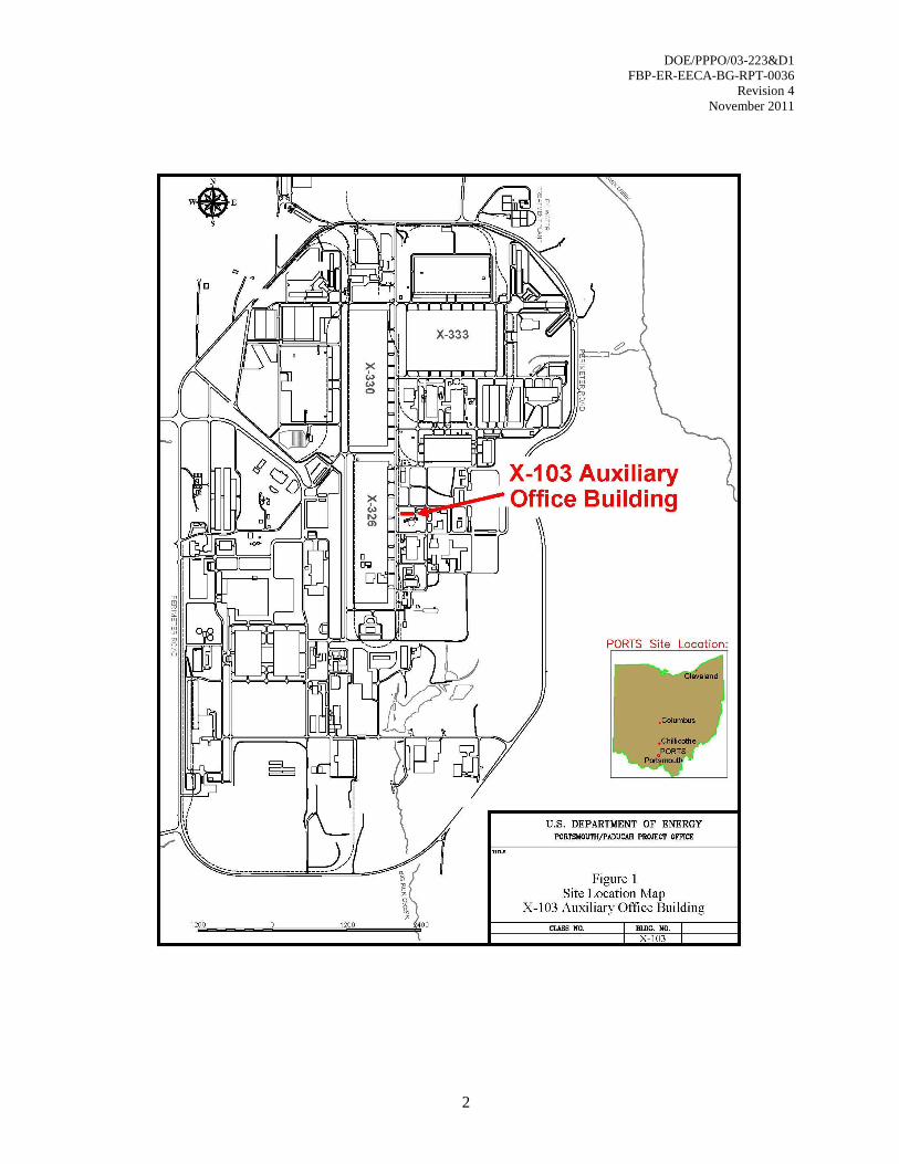
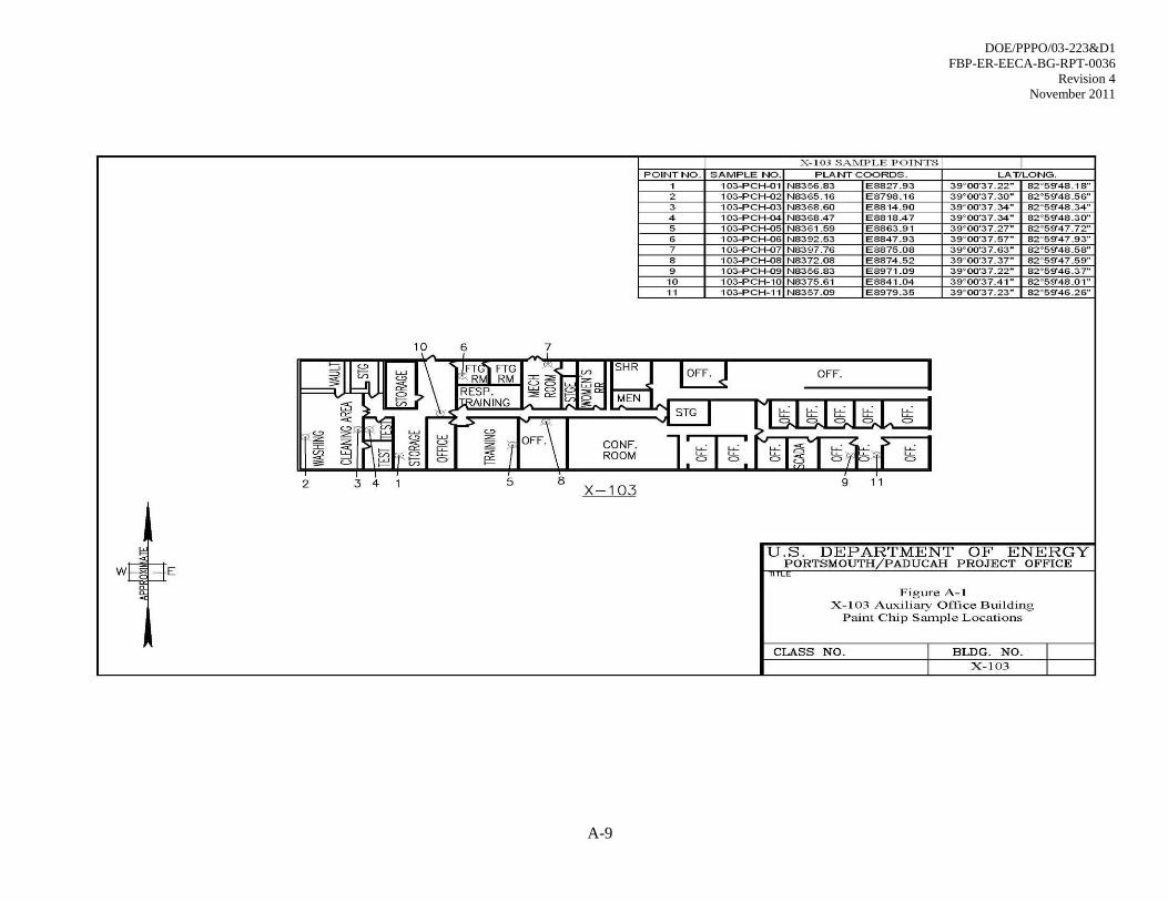
The X-103 Building was located at coordinates N8400, E8300 in Quadrant I of the Portsmouth Gaseous
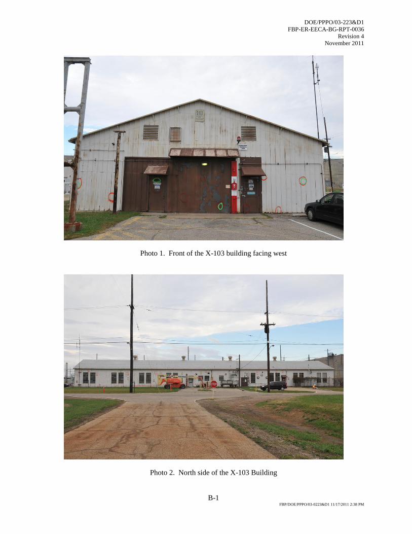
Diffusion Plant (PORTS). Figure 1 shows the location of the former X-103 Building at the plant site.
Figure 2 shows a detailed layout of the X-103 Building. Figures 3 and 4 are photographs of the X-103
Building.
1.1 REMOVAL ACTION COMPLETION REPORT PURPOSE AND SCOPE
This RACR documents completion of the X-103 Building DFF&O removal action, as described in the
Removal Action Work Plan for the X-103 Auxiliary Office Building at the Portsmouth Gaseous Diffusion
Plant, Piketon, Ohio (DOE 2011) (RAWP). Removal action alternatives for the X-103 Building were
evaluated in the Engineering Evaluation/Cost Analysis for Group 1 Buildings X-103, X-334, and X-344B
at the Portsmouth Gaseous Diffusion Plant, Piketon, Ohio (EE/CA) (DOE 2010a), and the decision to
remove the X-103 Building was documented in the Action Memorandum for the Group 1 Buildings
X-103, X-334, and X-344B at the Portsmouth Gaseous Diffusion Plant, Piketon, Ohio (Action
Memorandum) (DOE 2010b). These documents were prepared in accordance with the DFF&O.
1.2 SITE DESCRIPTION AND HISTORY
The X-103 Building was located in the west-central portion of PORTS in the area identified as Quadrant
I. Groundwater monitoring and remediation activities at PORTS have been conducted in four areas (or
quadrants) defined by the direction of groundwater and surface water flow in accordance with the
Consent Decree and the Integrated Groundwater Monitoring Plan for the Portsmouth Gaseous Diffusion
Plant, Piketon, Ohio that was in effect at the time the samples were collected.
The X-103 Building was a one-story, steel-framed, 10,000-sq-ft building on a concrete slab, located in
Quadrant I of PORTS. The X-103 Building was originally constructed in 1954 as a garage, and was
subsequently used as the respirator facility and offices. The X-103 Building was electrically heated and
air-conditioned by recirculating cooling water.
DOE/PPPO/03-223&D1
FBP-ER-EECA-BG-RPT-0036
Revision 4
November 2011
2

DOE/PPPO/03-223&D1
FBP-ER-EECA-BG-RPT-0036
Revision 4
November 2011
3

DOE/PPPO/03-223&D1
FBP-ER-EECA-BG-RPT-0036
Revision 4
November 2011
4
Figure 3. Photograph of front of X-103 Building facing west.
Figure 4. Photograph of north side of X-103 Building facing west.

DOE/PPPO/03-223&D1
FBP-ER-EECA-BG-RPT-0036
Revision 4
November 2011
5
At the time the non-time-critical removal action began, the X-103 Building contained offices, restrooms,
storage rooms, a mechanical equipment room, a conference room, a respirator washing and cleaning area,
and a vault in the northwest corner of the building. The concrete vault securely stored sealed sources of
radiological isotopes, Radium-226 (Ra) and Cesium-137 (Cs). The sources were used to expose
thermoluminescent dosimeters (TLDs) to a known level of radiation to aid in checking and calibrating the
TLD system instruments.
The X-103 Building was vacated in 2006 while it was leased to the United States Enrichment Corporation
(USEC). The X-103 Building was returned to DOE on December 11, 2009, and remained vacant until it
was demolished. The demolition of the X-103 Building commenced on March 7, 2011, and demolition
activities were completed on June 28, 2011.
1.3 CONTAMINANTS OF CONCERN
Based on previous reports and characterization data, which are summarized in the EE/CA (DOE 2010a),
lead, polychlorinated biphenyls (PCBs), and radiological constituents were contaminants of concern in the
X-103 Building. Lead-based paint was present on interior and exterior doors, floors, and walls. PCBs
were potentially present in fluorescent light ballasts. Two fixed radiological sources were in sealed units
in the secured vault in the northwest corner of the building. These sources were used to expose TLDs to a
known level of radiation to aid in checking and calibrating the TLD system instruments.
This historical information and process knowledge were supplemented by sampling and analyses of the
building components that were expected to remain after the pre-decontamination and decommissioning
(pre-D&D) activities were completed. Sampling and analyses were conducted in accordance with the
provisions of the Sampling and Analysis Plan for the X-103 Auxiliary Office Building at the Portsmouth
Gaseous Diffusion Plant, Piketon, Ohio (SAP) (DOE 2010c). Because the Phase II activities were added
to the RAWP after implementation of the SAP, additional sampling and analyses were conducted to
further characterize the concrete slab. Analytical results were reported in the X-103 RAWP and are
summarized below. Data summaries and figures showing the locations from which samples were
collected are provided in Appendix A.
1.3.1 Summary of Data Reported in the X-103 RAWP
1.3.1.1 Superstructure
Paint Chips
Based on analytical results from paint chips collected from the X-103 Building in July 2010, lead-based
paint was present on the surfaces of interior walls of the facility. Low levels of PCBs were also detected
in all of the paint chips that were collected. The paint chip data is presented in Appendix A, Table A.1.
A drawing showing the locations from which these samples were collected is also provided in Appendix
A. Based on these data, additional samples were collected from the building components present in the
X-103 Building superstructure and analyzed for total RCRA-designated metals and PCBs.
DOE/PPPO/03-223&D1
FBP-ER-EECA-BG-RPT-0036
Revision 4
November 2011
6
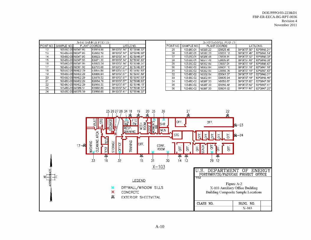
Building Components
Samples of individual building components were collected in September 2010 using a hammer and chisel
or, in the case of the exterior metal walls, a pair of tin snips. Figures presenting sample locations, and
tables comprising analytical results are included in Appendix A. Sample locations were selected so that
each significant building component would be represented in a composite sample in the same relative
proportion that the component was identified in the building. Sample locations were also biased based on
observable conditions (e.g., staining) to provide worst-case results.
Three composite samples were prepared. The first composite (Sample Number 103-BC-04-01) was from
the concrete walls at the west end of the building and consisted of 4 aliquots. The second composite
(Sample Number 103-BC-04-02) was from interior building components (e.g., drywall, window sills,
etc.) and consisted of 8 aliquots. The third composite (Sample Number 103-BC-04-03) was from the
exterior metal walls and was composed of 13 aliquots. These samples were initially analyzed for PCBs
and total Resource Conservation and Recovery Act (RCRA) metals.
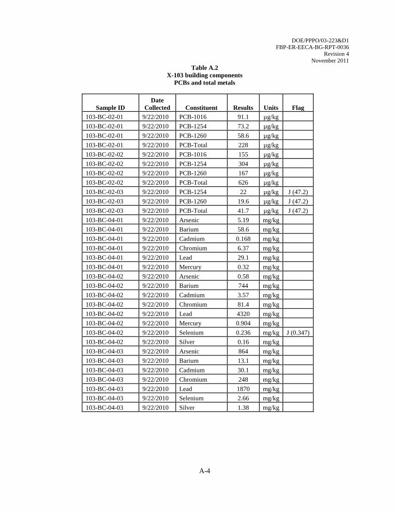
PCB results from the building components are presented in Table A.2 in Appendix A. PCBs were
detected in all of the building composites at concentrations ranging from 41.7 micrograms per kilogram
(µg/kg) to 626 µg/kg. The highest reading, which is well below the regulatory threshold of 50 milligrams
per kilograms (mg/kg), was in the composite from the interior building materials.
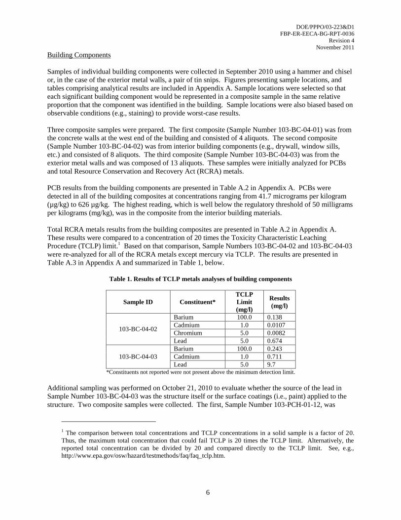
Total RCRA metals results from the building composites are presented in Table A.2 in Appendix A.
These results were compared to a concentration of 20 times the Toxicity Characteristic Leaching
Procedure (TCLP) limit.1 Based on that comparison, Sample Numbers 103-BC-04-02 and 103-BC-04-03
were re-analyzed for all of the RCRA metals except mercury via TCLP. The results are presented in
Table A.3 in Appendix A and summarized in Table 1, below.
Table 1. Results of TCLP metals analyses of building components
Sample ID Constituent*
TCLP
Limit
(mg/l)
Results
(mg/l)
103-BC-04-02
Barium 100.0 0.138
Cadmium 1.0 0.0107
Chromium 5.0 0.0082
Lead 5.0 0.674
103-BC-04-03
Barium 100.0 0.243
Cadmium 1.0 0.711
Lead 5.0 9.7 *Constituents not reported were not present above the minimum detection limit.
Additional sampling was performed on October 21, 2010 to evaluate whether the source of the lead in
Sample Number 103-BC-04-03 was the structure itself or the surface coatings (i.e., paint) applied to the
structure. Two composite samples were collected. The first, Sample Number 103-PCH-01-12, was
1 The comparison between total concentrations and TCLP concentrations in a solid sample is a factor of 20.
Thus, the maximum total concentration that could fail TCLP is 20 times the TCLP limit. Alternatively, the
reported total concentration can be divided by 20 and compared directly to the TCLP limit. See, e.g.,
http://www.epa.gov/osw/hazard/testmethods/faq/faq_tclp.htm.

DOE/PPPO/03-223&D1
FBP-ER-EECA-BG-RPT-0036
Revision 4
November 2011
7
collected from paint which was scraped from locations immediately adjacent to the locations from which
the original building composite (Sample Number 103-BC-04-03) was collected. The second composite,
Sample Number 103-BC-01-01, was collected from the wall after the paint was removed. The results are
provided in Appendix A and in Table 2, below. The majority of the lead detected in previous samples is
clearly present in the thin layer of paint on the exterior surface of the building.
Table 2. Results of TCLP-lead analyses of exterior paint and walls
Sample ID Constituent
TCLP
Limit
(mg/l)
TCLP
Results
(mg/l)
103-PCH-01-12 Lead 5.0 49.7
103-BC-01-01 Lead 5.0 3.75
In order to characterize the building as a whole for disposal purposes, a weight-based mathematical
composite of the TCLP data from the various building components was prepared. Those calculations are
provided in Table 3. Note that this mathematical composite does not include the inside building
components (e.g., drywall and windows) because a then-undetermined portion of those components were
expected to be removed and disposed of during pre-D&D actions. Similarly, the concrete slab was not
included because it had not been determined whether Phase II removal actions would be performed at the
same time as the Phase I removal. Omitting these nonhazardous building components from the
evaluation adds conservatism to the results. Based on the calculations, the composite of building materials
is characterized as a solid (i.e., nonhazardous) waste.
Table 3. Mathematical composite calculations
A
Building
Component
B
Weight
(lbs)
C
TCLP Lead
(mg/l)
D=BxC
Product
(lbs∙mg/l)
Paint 264 49.7 13,121
Steel Walls 19,200 3.75 72,000
Concrete Walls 102,240 1.455 148,759
Summation 121,704 233,880
Composite TCLP Lead 233,880 / 121,704 = 1.92 mg/l
Note that because TCLP analyses were not run on the concrete wall sample, the presumed TCLP lead
concentration assigned to that component in the above calculation is the highest TCLP concentration
possible based on the total lead concentration reported for the concrete walls (assuming 100% of the lead
leaches from the sample). The actual concentration is likely much lower. Again, this yields a highly
conservative result, especially given that the concrete walls account for over 80% of the total material.
Two disposition pathways were identified for the painted steel walls. As a recyclable scrap metal, they
fell within the exemption at Ohio Administrative Code (OAC) Section 3745-51-06(A)(3)(b) and would
not be subject to regulation as a hazardous waste regardless of their TCLP lead concentration.
Alternatively, if the walls were managed as a solid waste with the other demolition debris from the X-103
Building, the composite results reflected in Table 3 demonstrate that the mixture of demolition debris is
nonhazardous.
The latter alternative was selected and the exterior steel walls were managed with the other building
materials from both the superstructure as sanitary waste.

DOE/PPPO/03-223&D1
FBP-ER-EECA-BG-RPT-0036
Revision 4
November 2011
8
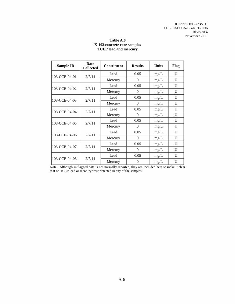
1.3.1.2 Concrete Slab
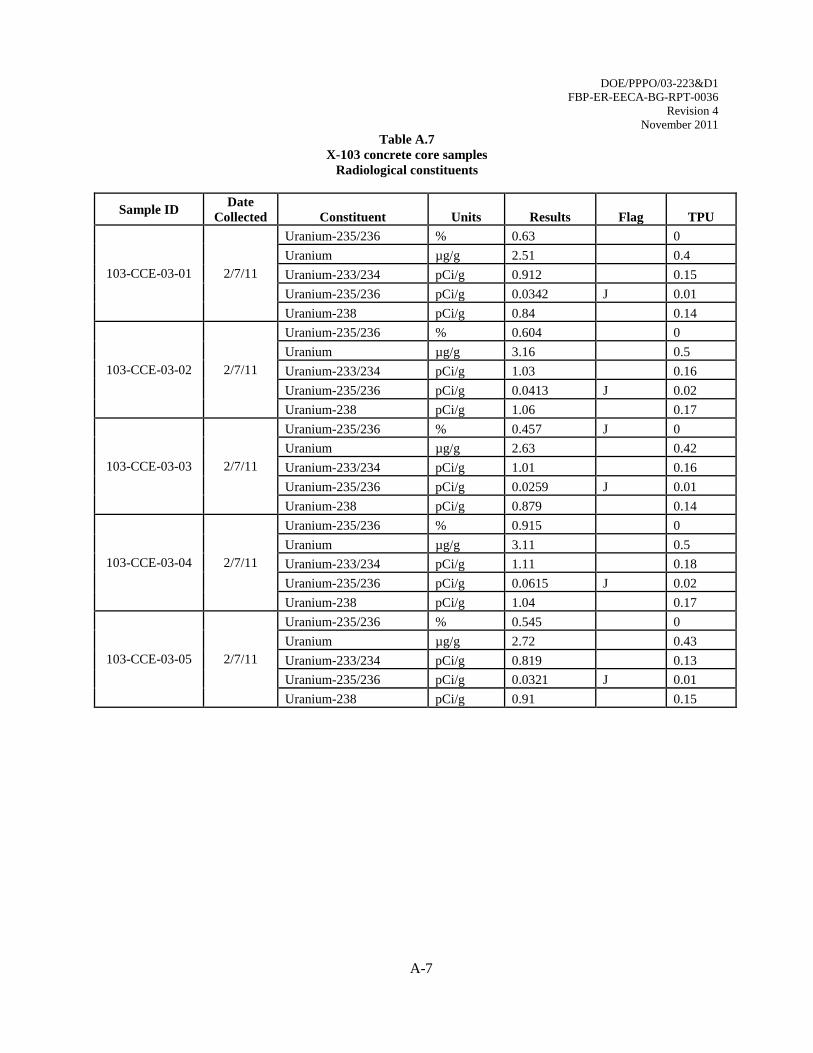
Eight concrete core samples were collected from the X-103 Building slab on February 7, 2011, for
laboratory determination of TCLP lead and mercury, PCBs, and radiological constituents. Based on the
results which are included in Tables A.5 through A.7 in Appendix A, the slab was characterized as a
sanitary waste.
1.3.1.3 Radiological Surveys
Other than the Ra-226 and Cs-137 sources discussed in Section 1.2, no processes involving radioactive
substances are known to have occurred in the X-103 Building. A radiological survey of the building and
surrounding area was conducted in 1995. An additional radiological survey was completed to confirm the
data from 1995. The survey addressed total and removable alpha and total and removable beta/gamma
radiation. Based on DOE Order 5400.5, the free-release criteria are an average of 5000 disintegrations
per minute (dpm) per 100 square centimeters (cm2) (and a maximum of 15,000 dpm/100 cm
2) for both
total alpha emitters and total beta/gamma emitters and 1000 dpm/100 cm2 for removable alpha and
removable beta/gamma emitters. The results of the survey, summarized in the
X-103 RAWP, met the free-release criteria.
Very few areas had survey results that were greater than the minimum detectable activity (MDA) and
even those results were less than the administrative release limit (80% of 10 Code of Federal Regulations
835 values). The only exception was the exterior roof of the building. There were multiple hits above the
MDA, leading to a 100% scan of the entire surface of the roof. Smears and static counts taken at highest
scan rate locations showed all results less than the release limits.
An additional survey was performed of the vault area after the radiological sources were removed. That
survey also indicated that the vault materials met free release limits.
1.4 PRE-DECONTAMINATION AND DECOMMISSIONING
Pre-D&D activities were conducted prior to the initiation of the DFF&O removal action described in this
document. The pre-D&D activities were performed under DOE’s independent authority under the Atomic
Energy Act and were executed in accordance with applicable statutory and regulatory requirements
including, but not limited to, the National Environmental Policy Act; Ohio’s Hazardous Waste Laws and
Rules, as found in Chapter 3734 of the Ohio Revised Code and Chapter 3745 of the OAC; OAC 3745-20
regarding asbestos; the requirements of the facility’s current hazardous waste permit; and the 1989
Consent Decree regarding the investigation and remediation of environmental media.
Significant pre-D&D activities at the X-103 Building included the removal of equipment and fluorescent
light fixtures and initial asbestos abatement activities. To facilitate the removal of asbestos-containing
asphalt floor tiles which were installed before the interior walls were constructed, portions of the interior
walls and doorways were also removed. As was anticipated in the EE/CA, the asbestos abatement
continued after the X-103 RAWP received concurrence from the Ohio EPA.
1.5 REMOVAL ACTION PURPOSE AND OBJECTIVES
The X-103 Building removal action activities were divided into two phases. The Phase I activities
included completion of the asbestos abatement activities, the removal of the two radiological sources,
demolition of the X-103 Building superstructure, and recycling or disposal of the Phase I demolition
materials. The Phase II activities included removal of the X-103 Building slab, removal of the
DOE/PPPO/03-223&D1
FBP-ER-EECA-BG-RPT-0036
Revision 4
November 2011
9
underground piping and utilities, restoration of the site, demobilization, and disposal of the Phase II
demolition materials.
The areal extent of the removal action was limited to the footprint of the X-103 Building, and within the
nominal distance of two feet beyond the X-103 Building footprint.
The following objectives were developed for the removal activities:
Reduce the potential exposure to on-site personnel from hazardous substances due to the
structural deterioration of the X-103 Building; and
Control removal of the X-103 Building to minimize or eliminate the potential health and
environmental impacts created by the potential uncontrolled release of contaminated dust,
equipment, and building materials from the structure as it deteriorates.
Meet applicable and relevant or appropriate requirements (ARARs) to the extent practicable,
Be protective of relevant receptors, and
Be cost effective.
2. SUMMARY OF TASKS COMPLETED
The X-103 Building DFF&O removal action activities have been completed in accordance with the
ARARs outlined in the Action Memorandum (DOE 2010b). Associated activities outlined in the X-103
Building ARARs were completed to meet the substantive requirements of the National Historic
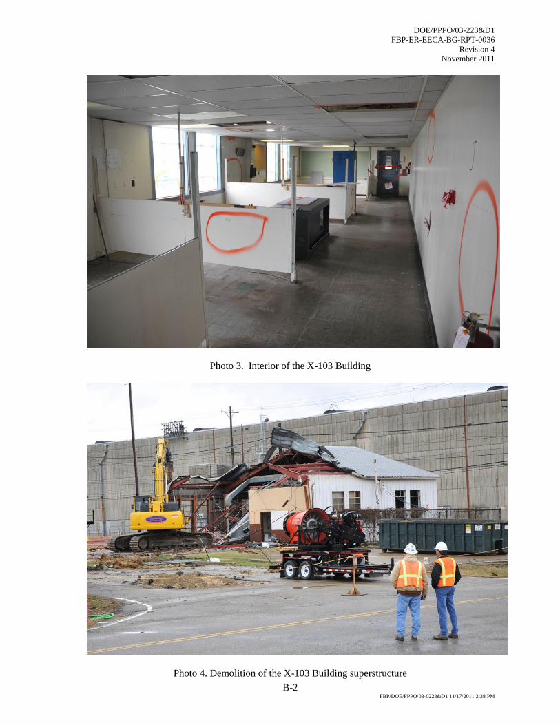
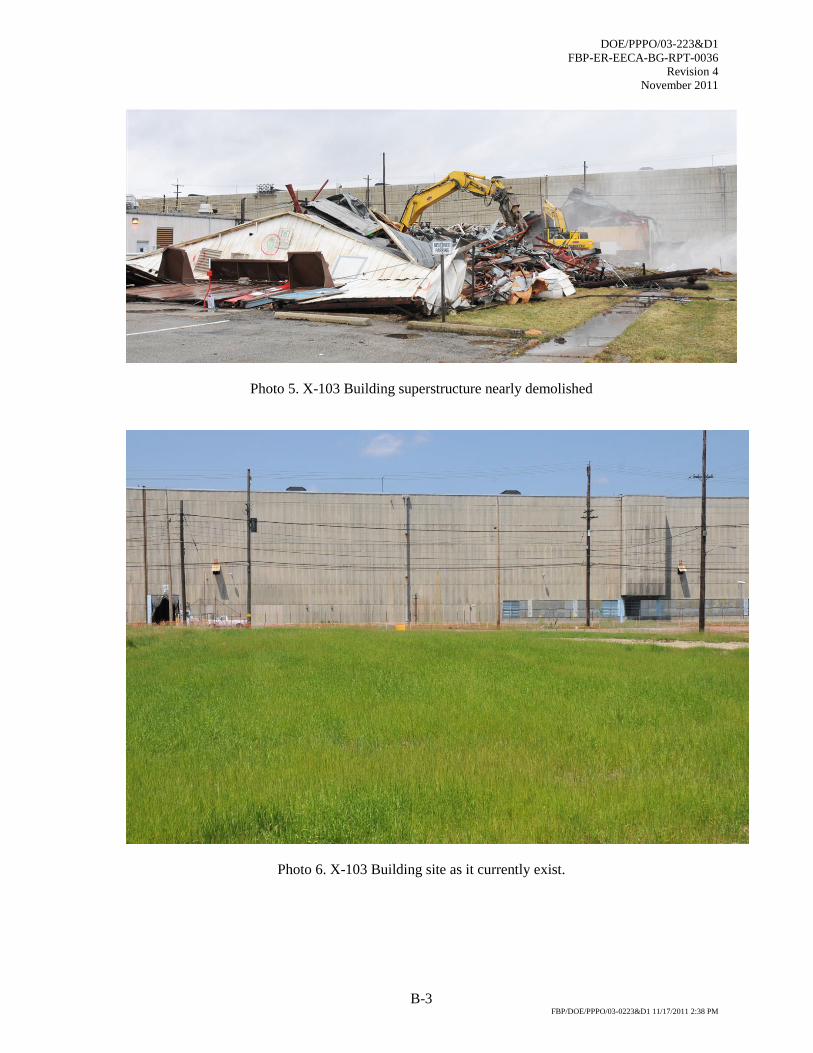
Preservation Act. Photographs of the X-103 Building before, during, and after demolition are provided in
Appendix B.
2.1 PHASE I ACTIVITIES
2.1.1 Continuation of Pre-D&D Activities
Prior to beginning demolition of the X-103 Building superstructure and slab, activities initially started as,
or initially planned as, pre-D&D activities were completed. This included completing the ongoing
asbestos abatement activities and removing the two radiological sources from the vault.
Asbestos Abatement
All identified asbestos-containing material (ACM) was removed from the X-103 Building using a
licensed asbestos abatement subcontractor. Engineering controls, including wetting methods, negative air
units, and containment structures, were used to control air emissions during Class I and Class II
abatement activities. Air monitoring was conducted to assure adequacy of engineering, administrative,
and personal protective equipment (PPE) controls. ACM was placed into Department of Transportation
(DOT)-approved containers for transportation to an approved local sanitary landfill for disposal.
Source Removal
The two radiological sources were removed from the X-103 Building on February 1, 2011. After opening
the vault and raising each source, each source was verified and placed in a special foam capsule. That
capsule was then sealed into a Hopewell shipping casket. The casket was cribbed inside a 55-gallon steel
drum and the lid sealed with a conventional slip-ring seal. The sources were then transported to the

DOE/PPPO/03-223&D1
FBP-ER-EECA-BG-RPT-0036
Revision 4
November 2011
10
X-326 storage area pending final disposition. The Ra-226 source was shipped to Oak Ridge National
Laboratory on March 23, 2011 for reuse at that location. The Cs-137 source was shipped to the Nevada
National Security Site on July 28, 2011.
2.1.2 Demolition of Above-Grade Structure
Demolition activities were performed in accordance with X-103 Building ARARs. The X-103 Building
above-grade structure was performed as a clean knockdown by positioning equipment and waste
containers strategically to maximize demolition rates, minimize distance between debris and containers,
and to prevent unsafe conditions.
Prior to demolition, pipes and drains in the slab were sealed and the hole in the slab resulting from
removal of the radiological sources was covered with a steel plate that was secured to the slab with metal
anchors. The above-grade demolition work was performed using long-reach 400-class excavators
equipped with bucket, shear, and grapple attachments. Demolition was accomplished by the controlled
sweeping of the excavator arm on the roof of the X-103 Building. Following the tearing of the roof,
building walls were pushed by the excavator arms toward the building center from the outside walls. The
excavators demolished the building walls and sheared the rubble to reduce it to a manageable size and to
meet the disposal facility’s waste acceptance criteria. The excavators cut and size-reduced the building to
cause it to collapse on itself. The entire building was reduced to rubble and loaded into DOT-approved
bulk waste haulers for transportation to an appropriately permitted and licensed local solid waste disposal
facility. No hazardous waste was generated, and no hazardous waste piles were created during the
removal activities.
During Phase I, a water mist was employed to minimize fugitive dust emissions. A sediment fence was
installed to control sediment migration from the work area. Sedimentation was also controlled by
minimizing the volume of water used for dust suppression.
2.2 PHASE II ACTIVITIES
2.2.1 Removal of Slab
The X-103 Building slab was demolished, followed by the primary foundations, in accordance with the
X-103 RAWP and X-103 Building ARARs. An excavator equipped with a power chisel was used to size
reduce the concrete. Once the materials were size-reduced, the debris was removed using an excavator
equipped with an excavation bucket. Concrete and asphalt driveways located on the northern and eastern
boundaries of the X-103 Building were also broken and removed.
Water was sprayed as necessary during Phase II demolition activities to minimize the release of fugitive
dust or other contaminants. Sediment and erosion controls were installed to control runoff.
Underground piping and utilities that were located beneath the footprint of the X-103 Building were
removed and terminated (i.e., capped and/or plugged) at a nominal distance of two feet outside of the
X-103 Building footprint.
Slab removal operations provided an opportunity to better observe the subsurface structure of the vault.
The radiological sources had been stored below grade and raised for use. This required a nominal four-
feet-square hole through the slab. During slab removal, a cylindrical hole was observed to extend below
the slab. That hole was formed by an approximate 30-inch diameter pipe that was covered with a tar-like
material. Based on visual observation, the pipe was suspected of containing asbestos.
DOE/PPPO/03-223&D1
FBP-ER-EECA-BG-RPT-0036
Revision 4
November 2011
11
Samples of both the pipe and the tar-like coating were collected and submitted for laboratory analyses for
asbestos and PCBs, respectively. The laboratory results indicated that the pipe did contain asbestos but
the coating did not contain PCBs. Based on that data, the pipe was removed on March 23, 2011 and
managed as asbestos waste.
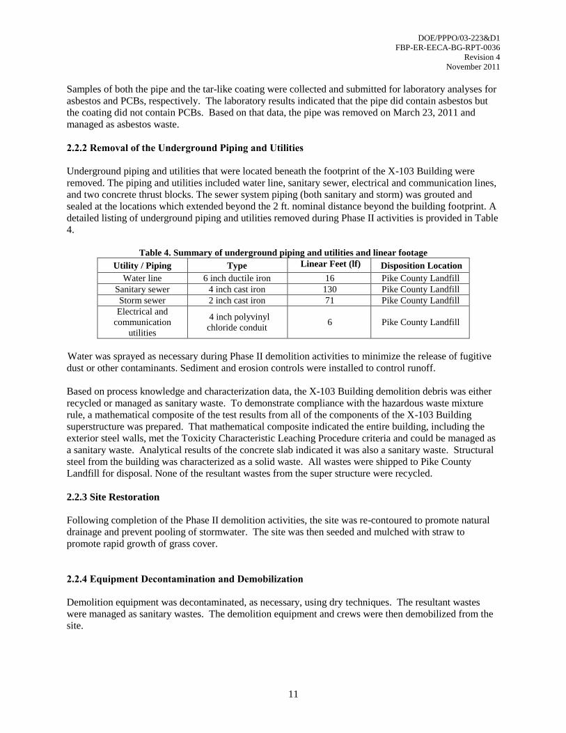
2.2.2 Removal of the Underground Piping and Utilities
Underground piping and utilities that were located beneath the footprint of the X-103 Building were
removed. The piping and utilities included water line, sanitary sewer, electrical and communication lines,
and two concrete thrust blocks. The sewer system piping (both sanitary and storm) was grouted and
sealed at the locations which extended beyond the 2 ft. nominal distance beyond the building footprint. A
detailed listing of underground piping and utilities removed during Phase II activities is provided in Table
4.
Table 4. Summary of underground piping and utilities and linear footage
Utility / Piping Type Linear Feet (lf) Disposition Location
Water line 6 inch ductile iron 16 Pike County Landfill
Sanitary sewer 4 inch cast iron 130 Pike County Landfill
Storm sewer 2 inch cast iron 71 Pike County Landfill
Electrical and
communication
utilities
4 inch polyvinyl
chloride conduit 6 Pike County Landfill
Water was sprayed as necessary during Phase II demolition activities to minimize the release of fugitive
dust or other contaminants. Sediment and erosion controls were installed to control runoff.
Based on process knowledge and characterization data, the X-103 Building demolition debris was either
recycled or managed as sanitary waste. To demonstrate compliance with the hazardous waste mixture
rule, a mathematical composite of the test results from all of the components of the X-103 Building
superstructure was prepared. That mathematical composite indicated the entire building, including the
exterior steel walls, met the Toxicity Characteristic Leaching Procedure criteria and could be managed as
a sanitary waste. Analytical results of the concrete slab indicated it was also a sanitary waste. Structural
steel from the building was characterized as a solid waste. All wastes were shipped to Pike County
Landfill for disposal. None of the resultant wastes from the super structure were recycled.
2.2.3 Site Restoration
Following completion of the Phase II demolition activities, the site was re-contoured to promote natural
drainage and prevent pooling of stormwater. The site was then seeded and mulched with straw to
promote rapid growth of grass cover.
2.2.4 Equipment Decontamination and Demobilization
Demolition equipment was decontaminated, as necessary, using dry techniques. The resultant wastes
were managed as sanitary wastes. The demolition equipment and crews were then demobilized from the
site.

DOE/PPPO/03-223&D1
FBP-ER-EECA-BG-RPT-0036
Revision 4
November 2011
12
2.3 POST-REMOVAL STATE
At the completion of this DFF&O removal action, the X-103 Building superstructure and slab have been
removed. Underground piping and utilities that were located beneath the footprint of the X-103 Building
were removed and terminated (i.e., capped and/or plugged) at a nominal distance of two feet outside of
the X-103 Building footprint. The site has been re-graded and seeded. All wastes have been removed
from the site.
3. WASTE MANAGEMENT AND TRANSPORTATION ACTIVITIES
This section describes the management, on-site staging, transport and disposal of wastes generated during
the X-103 Building DFF&O removal action. Wastes were staged on-site at the X-633-2C Recirculating
Cooling Water (RCW) Complex and/or transported and disposed off-site in accordance with the
X-103 Building RAWP and ARARs. Facility characterization was conducted to assure waste streams
were compliant with applicable waste acceptance criteria.
During Phase I, demolition waste from the X-103 Building superstructure was disposed as solid waste.
After the superstructure was completely removed, the concrete rubble from the slab was taken to the
X-633 RCW-2C basin and staged on-site as clean hard fill. Personal protective equipment used during
the removal action (e.g., gloves, earplugs) and wastes generated during dry decontamination activities
were disposed as sanitary wastes. The quantities and types of solid waste generated during this DFF&O
removal action and waste disposal locations are provided in Table 5.
Table 5. Summary of removal action solid waste
Waste Material Type Total Volume
(cu yd) Disposition Location
Phase I demolition debris Solid waste 1450 Pike County Landfill
Phase II concrete Clean hard fill 10,000 PORTS clean hard fill
stockpile
Phase II utilities and
piping Solid waste
*223 lf Pike County Landfill
*The total linear footage provided for Phase II underground piping and utilities.
Additional waste streams were also generated and disposed offsite. This information is provided in
Appendix C.
DOE/PPPO/03-223&D1
FBP-ER-EECA-BG-RPT-0036
Revision 4
November 2011
13
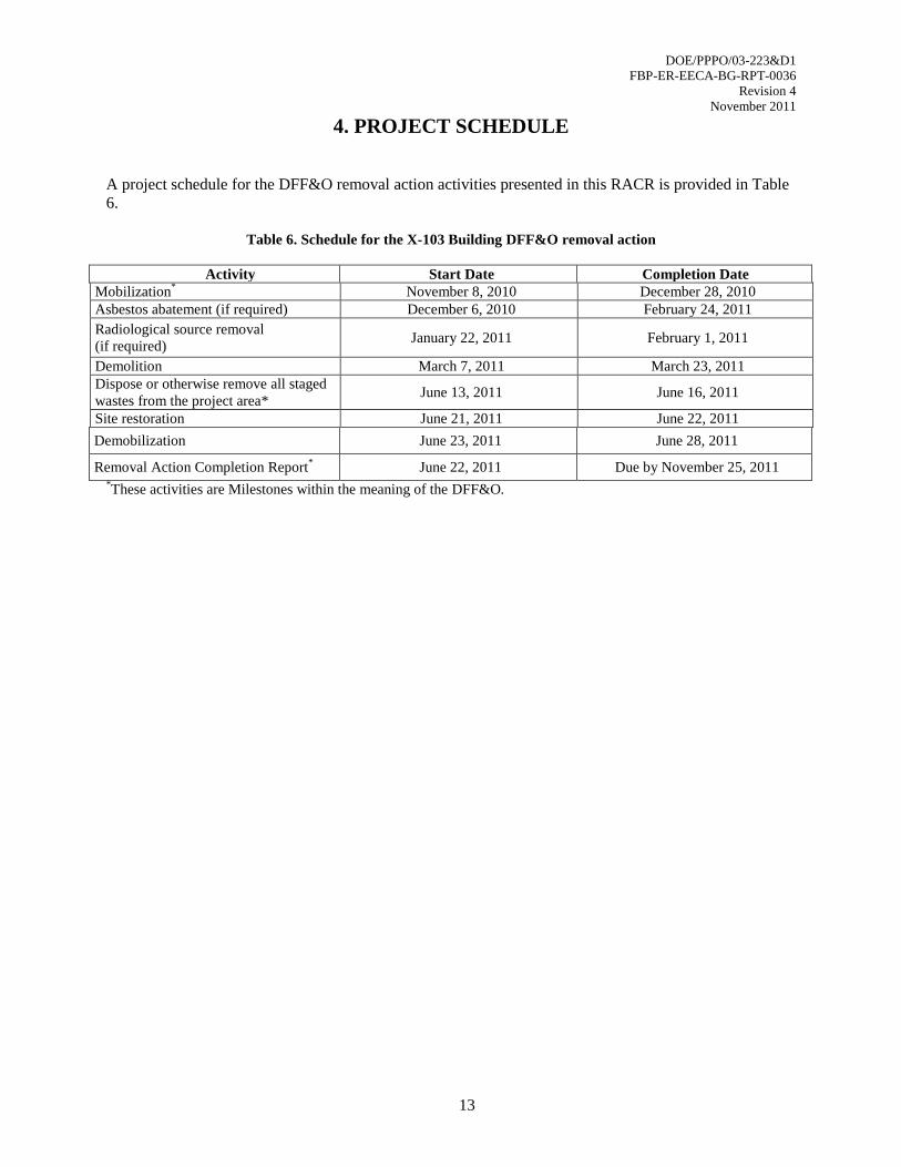
4. PROJECT SCHEDULE
A project schedule for the DFF&O removal action activities presented in this RACR is provided in Table
6.
Table 6. Schedule for the X-103 Building DFF&O removal action
Activity Start Date Completion Date
Mobilization* November 8, 2010 December 28, 2010
Asbestos abatement (if required) December 6, 2010 February 24, 2011
Radiological source removal
(if required) January 22, 2011 February 1, 2011
Demolition March 7, 2011 March 23, 2011
Dispose or otherwise remove all staged
wastes from the project area* June 13, 2011 June 16, 2011
Site restoration June 21, 2011 June 22, 2011
Demobilization June 23, 2011 June 28, 2011
Removal Action Completion Report* June 22, 2011 Due by November 25, 2011
*These activities are Milestones within the meaning of the DFF&O.
DOE/PPPO/03-223&D1
FBP-ER-EECA-BG-RPT-0036
Revision 4
November 2011
14
5. REFERENCES
Bechtel Jacobs 2001. Due Diligence for the Return of Portsmouth Leased Facilities from the United
States Enrichment Corporation to the U. S. Department of Energy. BJC/PORTS-251. June.
DOE 2010a. Engineering Evaluation/Cost Analysis for Group 1 Buildings X-103, X-334, and X-344B at
the Portsmouth Gaseous Diffusion Plant, Piketon, Ohio. DOE/PPPO/03-0145&D2.
DOE 2010b. Action Memorandum for the Group 1 Buildings X-103, X-334, and X-344B at the
Portsmouth Gaseous Diffusion Plant, Piketon, Ohio. DOE/PPPO/03-0177&D3.
DOE 2010c. Sampling and Analysis Plan for the X-103 Auxiliary Office Building at the Portsmouth
Gaseous Diffusion Plant, Piketon, Ohio. DOE/PPPO/03-0138&D3.
DOE 2011. Removal Action Work Plan for the X-103 Auxiliary Office Building at the Portsmouth
Gaseous Diffusion Plant, Piketon, Ohio, DOE/PPPO/03-0165&D1.
Ohio EPA 2010. Directors Final Findings and Orders for Removal Action and Remedial Investigation
and Feasibility Study and Remedial Design and Remedial Action for the DOE Portsmouth Gaseous
Diffusion Plant (Decontamination and Decommissioning Project). April.
TPMC 2006. Facility Condition Survey of the Portsmouth Gaseous Diffusion Plant Facilities, Piketon,
Ohio. TPMC/PORTS-59/R1. August.
DOE/PPPO/03-223&D1
FBP-ER-EECA-BG-RPT-0036
Revision 4
November 2011
APPENDIX A
X-103 ANALYTICAL DATA
DOE/PPPO/03-223&D1
FBP-ER-EECA-BG-RPT-0036
Revision 4
November 2011
A-1
Notes to Appendix A
Data Qualifiers (Flags)
Data qualifiers provide information from the laboratory that assists in interpreting the
reported qualitative and quantitative data. The qualifiers applicable to this data set are:
U – Indicates that the compound was analyzed for but not detected. U-qualified data was
not included in the data summaries in this Appendix.
J – Indicates an estimated value. This flag is used in cases where a target analyte
(constituent) is detected at a level less than the lower quantification level. When the
J-flag is reported, the lower quantification limit is also reported in parentheses
following the qualifier.
D – Indicates the compound was identified in an analysis at a secondary dilution factor.
Sample IDs
The third field in the Sample ID indicates the type of analysis requested at the time the
sample was submitted to the laboratory. For example, 103-PCH-02-01 indicates the first
(-01) paint chip sample (PCH) collected from the X-103 Building (103) to be analyzed
for PCBs (-02). Similarly, 103-BC-04-02 indicates this is the second (-02) building
component (BC) sample from the X-103 Building with requested analysis for total RCRA
metals (-04). To conserve space and because multiple analyses may be requested of the
same sample, the third field in the Sample ID is omitted from the drawings in this
Appendix.

DOE/PPPO/03-223&D1
FBP-ER-EECA-BG-RPT-0036
Revision 4
November 2011
A-2
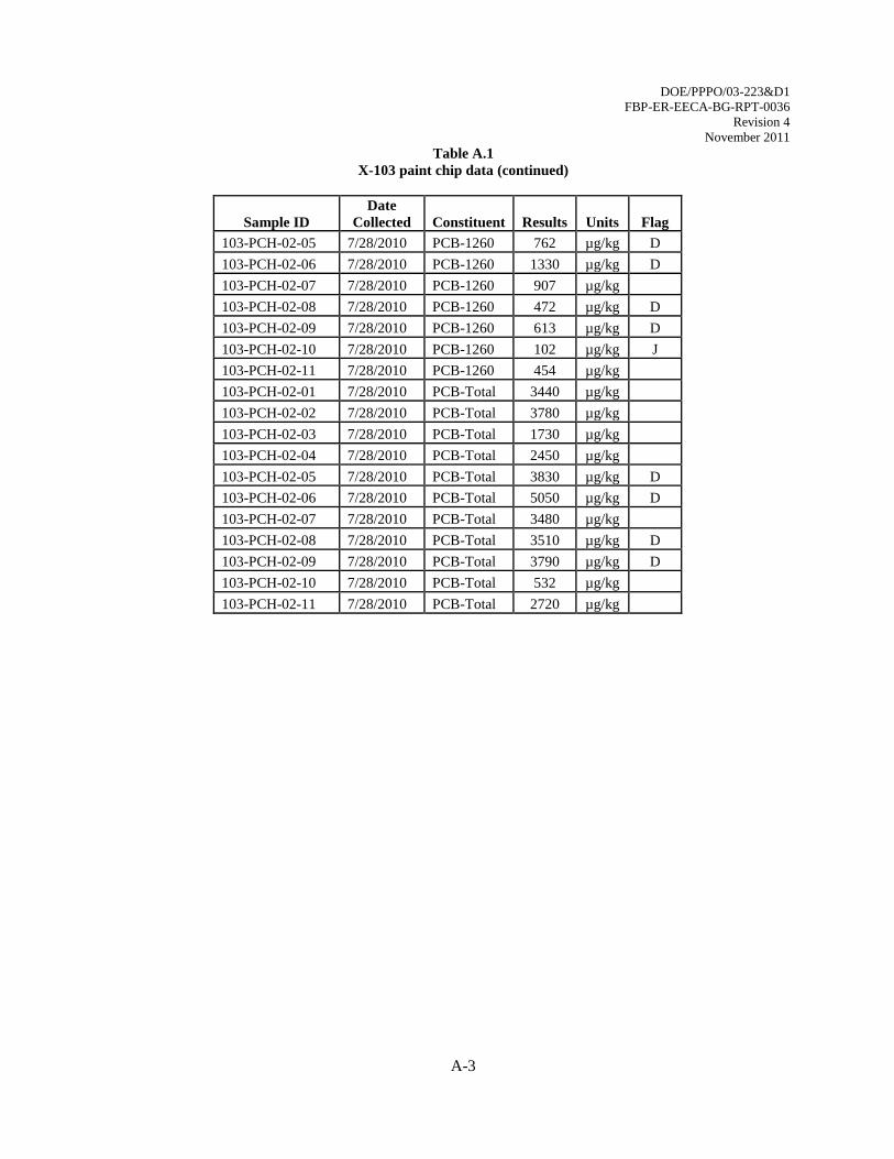
Table A.1
X-103 paint chip data
Sample ID
Date
Collected Constituent Results Units Flag
103-PCH-01-01 7/28/2010 Lead 16.8 mg/kg
103-PCH-01-02 7/28/2010 Lead 506 mg/kg
103-PCH-01-03 7/28/2010 Lead 29.7 mg/kg
103-PCH-01-04 7/28/2010 Lead 39.8 mg/kg
103-PCH-01-05 7/28/2010 Lead 5.08 mg/kg
103-PCH-01-06 7/28/2010 Lead 31.4 mg/kg
103-PCH-01-07 7/28/2010 Lead 34.6 mg/kg
103-PCH-01-08 7/28/2010 Lead 4.45 mg/kg
103-PCH-01-09 7/28/2010 Lead 1.31 mg/kg
103-PCH-01-10 7/28/2010 Lead 4.59 mg/kg
103-PCH-01-11 7/28/2010 Lead 31.2 mg/kg
103-PCH-02-01 7/28/2010 PCB-1016 1290 µg/kg
103-PCH-02-02 7/28/2010 PCB-1016 1300 µg/kg
103-PCH-02-03 7/28/2010 PCB-1016 1010 µg/kg
103-PCH-02-04 7/28/2010 PCB-1016 1260 µg/kg
103-PCH-02-05 7/28/2010 PCB-1016 1950 µg/kg D
103-PCH-02-07 7/28/2010 PCB-1016 1520 µg/kg
103-PCH-02-10 7/28/2010 PCB-1016 284 µg/kg
103-PCH-02-06 7/28/2010 PCB-1242 2040 µg/kg D
103-PCH-02-08 7/28/2010 PCB-1242 2150 µg/kg D
103-PCH-02-09 7/28/2010 PCB-1242 2300 µg/kg D
103-PCH-02-11 7/28/2010 PCB-1242 1390 µg/kg
103-PCH-02-01 7/28/2010 PCB-1254 762 µg/kg
103-PCH-02-02 7/28/2010 PCB-1254 1330 µg/kg
103-PCH-02-03 7/28/2010 PCB-1254 423 µg/kg
103-PCH-02-04 7/28/2010 PCB-1254 596 µg/kg
103-PCH-02-05 7/28/2010 PCB-1254 1110 µg/kg D
103-PCH-02-06 7/28/2010 PCB-1254 1680 µg/kg D
103-PCH-02-07 7/28/2010 PCB-1254 1050 µg/kg
103-PCH-02-08 7/28/2010 PCB-1254 885 µg/kg D
103-PCH-02-09 7/28/2010 PCB-1254 880 µg/kg D
103-PCH-02-10 7/28/2010 PCB-1254 146 µg/kg J (177)
103-PCH-02-11 7/28/2010 PCB-1254 875 µg/kg
103-PCH-02-01 7/28/2010 PCB-1260 1390 µg/kg
103-PCH-02-02 7/28/2010 PCB-1260 1150 µg/kg
103-PCH-02-03 7/28/2010 PCB-1260 295 µg/kg
103-PCH-02-04 7/28/2010 PCB-1260 601 µg/kg
DOE/PPPO/03-223&D1
FBP-ER-EECA-BG-RPT-0036
Revision 4
November 2011
A-3
Table A.1
X-103 paint chip data (continued)
Sample ID
Date
Collected Constituent Results Units Flag
103-PCH-02-05 7/28/2010 PCB-1260 762 µg/kg D
103-PCH-02-06 7/28/2010 PCB-1260 1330 µg/kg D
103-PCH-02-07 7/28/2010 PCB-1260 907 µg/kg
103-PCH-02-08 7/28/2010 PCB-1260 472 µg/kg D
103-PCH-02-09 7/28/2010 PCB-1260 613 µg/kg D
103-PCH-02-10 7/28/2010 PCB-1260 102 µg/kg J
103-PCH-02-11 7/28/2010 PCB-1260 454 µg/kg
103-PCH-02-01 7/28/2010 PCB-Total 3440 µg/kg
103-PCH-02-02 7/28/2010 PCB-Total 3780 µg/kg
103-PCH-02-03 7/28/2010 PCB-Total 1730 µg/kg
103-PCH-02-04 7/28/2010 PCB-Total 2450 µg/kg
103-PCH-02-05 7/28/2010 PCB-Total 3830 µg/kg D
103-PCH-02-06 7/28/2010 PCB-Total 5050 µg/kg D
103-PCH-02-07 7/28/2010 PCB-Total 3480 µg/kg
103-PCH-02-08 7/28/2010 PCB-Total 3510 µg/kg D
103-PCH-02-09 7/28/2010 PCB-Total 3790 µg/kg D
103-PCH-02-10 7/28/2010 PCB-Total 532 µg/kg
103-PCH-02-11 7/28/2010 PCB-Total 2720 µg/kg
DOE/PPPO/03-223&D1
FBP-ER-EECA-BG-RPT-0036
Revision 4
November 2011
A-4
Table A.2
X-103 building components
PCBs and total metals
Sample ID
Date
Collected Constituent Results Units Flag
103-BC-02-01 9/22/2010 PCB-1016 91.1 µg/kg
103-BC-02-01 9/22/2010 PCB-1254 73.2 µg/kg
103-BC-02-01 9/22/2010 PCB-1260 58.6 µg/kg
103-BC-02-01 9/22/2010 PCB-Total 228 µg/kg
103-BC-02-02 9/22/2010 PCB-1016 155 µg/kg
103-BC-02-02 9/22/2010 PCB-1254 304 µg/kg
103-BC-02-02 9/22/2010 PCB-1260 167 µg/kg
103-BC-02-02 9/22/2010 PCB-Total 626 µg/kg
103-BC-02-03 9/22/2010 PCB-1254 22 µg/kg J (47.2)
103-BC-02-03 9/22/2010 PCB-1260 19.6 µg/kg J (47.2)
103-BC-02-03 9/22/2010 PCB-Total 41.7 µg/kg J (47.2)
103-BC-04-01 9/22/2010 Arsenic 5.19 mg/kg
103-BC-04-01 9/22/2010 Barium 58.6 mg/kg
103-BC-04-01 9/22/2010 Cadmium 0.168 mg/kg
103-BC-04-01 9/22/2010 Chromium 6.37 mg/kg
103-BC-04-01 9/22/2010 Lead 29.1 mg/kg
103-BC-04-01 9/22/2010 Mercury 0.32 mg/kg
103-BC-04-02 9/22/2010 Arsenic 0.58 mg/kg
103-BC-04-02 9/22/2010 Barium 744 mg/kg
103-BC-04-02 9/22/2010 Cadmium 3.57 mg/kg
103-BC-04-02 9/22/2010 Chromium 81.4 mg/kg
103-BC-04-02 9/22/2010 Lead 4320 mg/kg
103-BC-04-02 9/22/2010 Mercury 0.904 mg/kg
103-BC-04-02 9/22/2010 Selenium 0.236 mg/kg J (0.347)
103-BC-04-02 9/22/2010 Silver 0.16 mg/kg
103-BC-04-03 9/22/2010 Arsenic 864 mg/kg
103-BC-04-03 9/22/2010 Barium 13.1 mg/kg
103-BC-04-03 9/22/2010 Cadmium 30.1 mg/kg
103-BC-04-03 9/22/2010 Chromium 248 mg/kg
103-BC-04-03 9/22/2010 Lead 1870 mg/kg
103-BC-04-03 9/22/2010 Selenium 2.66 mg/kg
103-BC-04-03 9/22/2010 Silver 1.38 mg/kg
DOE/PPPO/03-223&D1
FBP-ER-EECA-BG-RPT-0036
Revision 4
November 2011
A-5
Table A.3
X-103 building components
TCLP metals
Sample ID Date
Collected Constituent
TCLP
Limit Results Units Flag
103-BC-04-02 9/22/2010 Barium 100.0 0.138 mg/L
103-BC-04-02 9/22/2010 Cadmium 1.0 0.0107 mg/L J (0.018)
103-BC-04-02 9/22/2010 Chromium 5.0 0.0082 mg/L J (0.03)
103-BC-04-02 9/22/2010 Lead 5.0 0.674 mg/L
103-BC-04-03 9/22/2010 Barium 100.0 0.243 mg/L
103-BC-04-03 9/22/2010 Cadmium 1.0 0.711 mg/L
103-BC-04-03 9/22/2010 Lead 5.0 9.7 mg/L
Table A.4
X-103 building exterior wall and paint
TCLP lead
Sample ID Date
Collected Constituent
TCLP
Limit Results Units Flag
103-PCH-01-12 10/21/2010 Lead 5.0 49.7 mg/L
103-BC-01-01 10/21/2010 Lead 5.0 3.75 mg/L
Table A.5
X-103 concrete core samples
PCBs
Sample ID
Date
Collected Constituent Results Units Flag
103-CCE-02-01 2/7/11 Total PCBs 37.1 µg/kg U
103-CCE-02-02 2/7/11 Total PCBs 42 µg/kg J
103-CCE-02-03 2/7/11 Total PCBs 62.4 µg/kg U
103-CCE-02-04 2/7/11 Total PCBs 39.5 µg/kg U
103-CCE-02-05 2/7/11 Total PCBs 64 µg/kg U
103-CCE-02-06 2/7/11 Total PCBs 39.3 µg/kg U
103-CCE-02-07 2/7/11 Total PCBs 71.9 µg/kg U
103-CCE-02-08 2/7/11 Total PCBs 40.3 µg/kg U
DOE/PPPO/03-223&D1
FBP-ER-EECA-BG-RPT-0036
Revision 4
November 2011
A-6
Table A.6
X-103 concrete core samples
TCLP lead and mercury
Sample ID Date
Collected Constituent Results Units Flag
103-CCE-04-01 2/7/11 Lead 0.05 mg/L U
Mercury 0 mg/L U
103-CCE-04-02 2/7/11 Lead 0.05 mg/L U
Mercury 0 mg/L U
103-CCE-04-03 2/7/11 Lead 0.05 mg/L U
Mercury 0 mg/L U
103-CCE-04-04 2/7/11 Lead 0.05 mg/L U
Mercury 0 mg/L U
103-CCE-04-05 2/7/11 Lead 0.05 mg/L U
Mercury 0 mg/L U
103-CCE-04-06 2/7/11 Lead 0.05 mg/L U
Mercury 0 mg/L U
103-CCE-04-07 2/7/11 Lead 0.05 mg/L U
Mercury 0 mg/L U
103-CCE-04-08 2/7/11 Lead 0.05 mg/L U
Mercury 0 mg/L U
Note: Although U-flagged data is not normally reported, they are included here to make it clear
that no TCLP lead or mercury were detected in any of the samples.
DOE/PPPO/03-223&D1
FBP-ER-EECA-BG-RPT-0036
Revision 4
November 2011
A-7
Table A.7
X-103 concrete core samples
Radiological constituents
Sample ID Date
Collected Constituent Units Results Flag TPU
103-CCE-03-01 2/7/11
Uranium-235/236 % 0.63 0
Uranium µg/g 2.51 0.4
Uranium-233/234 pCi/g 0.912 0.15
Uranium-235/236 pCi/g 0.0342 J 0.01
Uranium-238 pCi/g 0.84 0.14
103-CCE-03-02 2/7/11
Uranium-235/236 % 0.604 0
Uranium µg/g 3.16 0.5
Uranium-233/234 pCi/g 1.03 0.16
Uranium-235/236 pCi/g 0.0413 J 0.02
Uranium-238 pCi/g 1.06 0.17
103-CCE-03-03 2/7/11
Uranium-235/236 % 0.457 J 0
Uranium µg/g 2.63 0.42
Uranium-233/234 pCi/g 1.01 0.16
Uranium-235/236 pCi/g 0.0259 J 0.01
Uranium-238 pCi/g 0.879 0.14
103-CCE-03-04 2/7/11
Uranium-235/236 % 0.915 0
Uranium µg/g 3.11 0.5
Uranium-233/234 pCi/g 1.11 0.18
Uranium-235/236 pCi/g 0.0615 J 0.02
Uranium-238 pCi/g 1.04 0.17
103-CCE-03-05 2/7/11
Uranium-235/236 % 0.545 0
Uranium µg/g 2.72 0.43
Uranium-233/234 pCi/g 0.819 0.13
Uranium-235/236 pCi/g 0.0321 J 0.01
Uranium-238 pCi/g 0.91 0.15
DOE/PPPO/03-223&D1
FBP-ER-EECA-BG-RPT-0036
Revision 4
November 2011
A-8
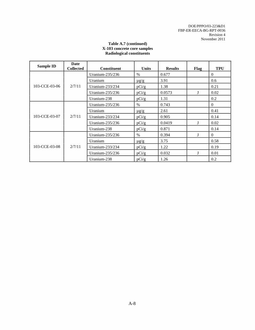
Table A.7 (continued)
X-103 concrete core samples
Radiological constituents
Sample ID Date
Collected Constituent Units Results Flag TPU
103-CCE-03-06 2/7/11
Uranium-235/236 % 0.677 0
Uranium µg/g 3.91 0.6
Uranium-233/234 pCi/g 1.38 0.21
Uranium-235/236 pCi/g 0.0573 J 0.02
Uranium-238 pCi/g 1.31 0.2
103-CCE-03-07 2/7/11
Uranium-235/236 % 0.743 0
Uranium µg/g 2.61 0.41
Uranium-233/234 pCi/g 0.905 0.14
Uranium-235/236 pCi/g 0.0419 J 0.02
Uranium-238 pCi/g 0.871 0.14
103-CCE-03-08 2/7/11
Uranium-235/236 % 0.394 J 0
Uranium µg/g 3.75 0.58
Uranium-233/234 pCi/g 1.22 0.19
Uranium-235/236 pCi/g 0.032 J 0.01
Uranium-238 pCi/g 1.26 0.2
DOE/PPPO/03-223&D1
FBP-ER-EECA-BG-RPT-0036
Revision 4
November 2011
A-9
DOE/PPPO/03-223&D1
FBP-ER-EECA-BG-RPT-0036
Revision 4
November 2011
A-10

DOE/PPPO/03-223&D1
FBP-ER-EECA-BG-RPT-0036
Revision 4
November 2011
A-11
APPENDIX B
PHOTOGRAPHS
DOE/PPPO/03-223&D1
FBP-ER-EECA-BG-RPT-0036
Revision 4
November 2011
B-1 FBP/DOE/PPPO/03-0223&D1 11/17/2011 2:38 PM
Photo 1. Front of the X-103 building facing west
Photo 2. North side of the X-103 Building
DOE/PPPO/03-223&D1
FBP-ER-EECA-BG-RPT-0036
Revision 4
November 2011
B-2 FBP/DOE/PPPO/03-0223&D1 11/17/2011 2:38 PM
Photo 3. Interior of the X-103 Building
Photo 4. Demolition of the X-103 Building superstructure
DOE/PPPO/03-223&D1
FBP-ER-EECA-BG-RPT-0036
Revision 4
November 2011
B-3 FBP/DOE/PPPO/03-0223&D1 11/17/2011 2:38 PM
Photo 5. X-103 Building superstructure nearly demolished
Photo 6. X-103 Building site as it currently exist.
APPENDIX C
WASTE SHIPMENT SUMMARY
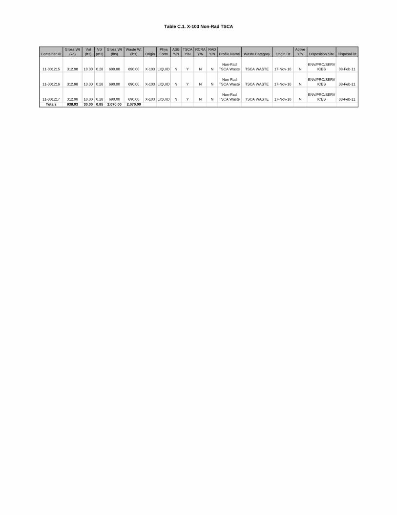
Table C.1. X-103 Non-Rad TSCA
Container IDGross Wt
(kg)Vol (ft3)
Vol (m3)
Gross Wt (lbs)
Waste Wt (lbs) Origin
Phys Form
ASB Y/N
TSCA Y/N
RCRA Y/N
RAD Y/N Profile Name Waste Category Origin Dt
Active Y/N Disposition Site Disposal Dt
11-001215 312.98 10.00 0.28 690.00 690.00 X-103 LIQUID N Y N NNon-Rad
TSCA Waste TSCA WASTE 17-Nov-10 NENV/PRO/SERV
ICES 08-Feb-11
11-001216 312.98 10.00 0.28 690.00 690.00 X-103 LIQUID N Y N NNon-Rad
TSCA Waste TSCA WASTE 17-Nov-10 NENV/PRO/SERV
ICES 08-Feb-11
11-001217 312.98 10.00 0.28 690.00 690.00 X-103 LIQUID N Y N NNon-Rad
TSCA Waste TSCA WASTE 17-Nov-10 NENV/PRO/SERV
ICES 08-Feb-11Totals 938.93 30.00 0.85 2,070.00 2,070.00
Table C.2. X-103 Pike Landfill Sanitary Waste
Container ID Gross Wt (kg) Vol (ft3) Vol (m3) Gross Wt (lbs) Waste Wt (lbs) Origin
Phys Form
ASB Y/N
TSCA Y/N
RCRA Y/N
RAD Y/N
Profile Name
Waste Category Origin Dt Active Y/N
Disposition Site Disposal Dt
10-002840 111,428.93 4,860.00 137.62 245,660.00 35,720.00 X-103 SOLID N N N N
Non-Rad, Non-RCRA Demolition
Debris
SANITARY/INDUSTRIAL
WASTE 16-Nov-10 NPIKE
LANDFILL 13-Dec-10
11-000441 237,976.01 7,290.00 206.43 524,650.00 220,450.00 X-103 SOLID N N N N
Non-Rad, Non-RCRA Demolition
Debris
SANITARY/INDUSTRIAL
WASTE 15-Mar-11 NPIKE
LANDFILL 17-Mar-11
11-000821 85,528.94 3,240.00 91.75 188,560.00 49,200.00 X-103 SOLID N N N N
Non-Rad, Non-RCRA Demolition
Debris
SANITARY/INDUSTRIAL
WASTE 14-Mar-11 NPIKE
LANDFILL 16-Mar-11
11-000822 46,756.06 2,160.00 61.17 103,080.00 31,840.00 X-103 SOLID N N N N
Non-Rad, Non-RCRA Demolition
Debris
SANITARY/INDUSTRIAL
WASTE 14-Mar-11 NPIKE
LANDFILL 14-Mar-11
11-000823 27,188.19 1,080.00 30.58 59,940.00 23,980.00 X-103 SOLID N N N N
Non-Rad, Non-RCRA Demolition
Debris
SANITARY/INDUSTRIAL
WASTE 15-Mar-11 NPIKE
LANDFILL 16-Mar-11
11-000824 101,658.60 3,240.00 91.75 224,120.00 87,200.00 X-103 SOLID N N N N
Non-Rad, Non-RCRA Demolition
Debris
SANITARY/INDUSTRIAL
WASTE 16-Mar-11 NPIKE
LANDFILL 23-Mar-11
11-002039 92,219.39 2,430.00 68.81 203,310.00 100,130.00 X-103 SOLID N N N N
Non-Rad, Non-RCRA Demolition
Debris
SANITARY/INDUSTRIAL
WASTE 17-Mar-01 NPIKE
LANDFILL 17-Mar-11
11-002075 75,776.75 2,430.00 68.81 167,060.00 55,600.00 X-103 SOLID N N N N
Non-Rad, Non-RCRA Demolition
Debris
SANITARY/INDUSTRIAL
WASTE 20-Apr-11 NPIKE
LANDFILL 20-May-11
11-002200 23,459.68 810.00 22.94 51,720.00 14,880.00 X-103 SOLID N N N N
Non-Rad, Non-RCRA Demolition
Debris
SANITARY/INDUSTRIAL
WASTE 11-May-11 NPIKE
LANDFILL 19-May-11
11-002201 25,373.83 810.00 22.94 55,940.00 17,960.00 X-103 SOLID N N N N
Non-Rad, Non-RCRA Demolition
Debris
SANITARY/INDUSTRIAL
WASTE 11-May-11 NPIKE
LANDFILL 19-May-11
11-002204 23,831.62 810.00 22.94 52,540.00 19,160.00 X-103 SOLID N N N N
Non-Rad, Non-RCRA Demolition
Debris
SANITARY/INDUSTRIAL
WASTE 12-May-11 NPIKE
LANDFILL 23-May-11
11-002205 25,927.21 810.00 22.94 57,160.00 21,040.00 X-103 SOLID N N N N
Non-Rad, Non-RCRA Demolition
Debris
SANITARY/INDUSTRIAL
WASTE 16-May-11 NPIKE
LANDFILL 20-May-11
11-002206 25,537.12 810.00 22.94 56,300.00 22,180.00 X-103 SOLID N N N N
Non-Rad, Non-RCRA Demolition
Debris
SANITARY/INDUSTRIAL
WASTE 16-May-11 NPIKE
LANDFILL 23-May-11
11-002207 25,836.49 810.00 22.94 56,960.00 20,000.00 X-103 SOLID N N N N
Non-Rad, Non-RCRA Demolition
Debris
SANITARY/INDUSTRIAL
WASTE 16-May-11 NPIKE
LANDFILL 19-May-11
11-002208 27,124.68 810.00 22.94 59,800.00 26,800.00 X-103 SOLID N N N N
Non-Rad, Non-RCRA Demolition
Debris
SANITARY/INDUSTRIAL
WASTE 12-May-11 NPIKE
LANDFILL 12-May-11
11-002511 7,511.45 810.00 22.94 16,560.00 10,760.00 X-103 SOLID N N N N
Non-Rad, Non-RCRA Demolition
Debris
SANITARY/INDUSTRIAL
WASTE 15-Jun-11 NPIKE
LANDFILL 17-Jun-11
1 of 2

Table C.2. X-103 Pike Landfill Sanitary Waste
Container ID Gross Wt (kg) Vol (ft3) Vol (m3) Gross Wt (lbs) Waste Wt (lbs) Origin
Phys Form
ASB Y/N
TSCA Y/N
RCRA Y/N
RAD Y/N
Profile Name
Waste Category Origin Dt Active Y/N
Disposition Site Disposal Dt
10-002841 19,377.37 810.00 22.94 42,720.00 8,380.00 X-103 SOLID Y N N N
Non-Rad, Non-RCRA
Friable ACM ASBESTOS 24-Feb-11 N
PIKE LANDFILL 02-Mar-11
11-001553 58,885.06 2,430.00 68.81 129,820.00 27,260.00 X-103 SOLID Y N N N
Non-Friable Asbestos
Containing Material ASBESTOS 14-Feb-11 N
PIKE LANDFILL 16-Feb-11
11-001554 19,722.09 1,080.00 30.58 43,480.00 7,280.00 X-103 SOLID Y N N N
Non-Rad, Non-RCRA
Friable ACM ASBESTOS 14-Feb-11 N
PIKE LANDFILL 16-Feb-11
11-001555 38,228.57 1,620.00 45.87 84,280.00 15,540.00 X-103 SOLID Y N N N
Non-Friable Asbestos
Containing Material ASBESTOS 15-Feb-11 N
PIKE LANDFILL 24-Feb-11
Totals 1,099,348.01 39,150.00 1,108.63 2,423,660.00 815,360.00
2 of 2

Table C.3. X-103 Recyclable/Universal Material
Container ID
Gross Wt (kg) Vol (ft3) Vol (m3)
Gross Wt (lbs)
Waste Wt (lbs) Origin
Phys Form
ASB Y/N
TSCA Y/N
RCRA Y/N
RAD Y/N Profile Name Waste Category Origin Dt Active Y/N
Disposition Site
11-001210 44.45 2.01 0.06 98.00 83.00 X-103 SOLID N N N N
RECYCLABLE
BATTERIES UNIVERSAL 25-Oct-10 N
USA LAMP & BALLAST
RECY.
11-001211 47.17 5.43 0.15 104.00 69.00 X-103 SOLID N N N N
RECYCLABLE CIRCUIT
BOARDS RECYCLE 02-Nov-10 N
USA LAMP & BALLAST
RECY.
11-001212 5.44 1.10 0.03 12.00 0.50 X-103 SOLID N N N N
RECYCLABLE
MERCURY RECYCLE 23-Nov-10 N
USA LAMP & BALLAST
RECY.
11-001213 6.35 1.10 0.03 14.00 2.00 X-103 SOLID N N N N
RECYCLABLE LIGHTS
AND LAMPS UNIVERSAL 23-Nov-10 N
USA LAMP & BALLAST
RECY.
11-000532 235.86 7.35 0.21 520.00 458.00 X-103 SOLID N N N NRECYCLABLE METALS RECYCLE 28-Mar-11 N
Cherrington Metals
11-001214 311.16 9.57 0.27 686.00 624.00 X-103 SOLID N Y N NNon-Rad
TSCA Waste TSCA WASTE 24-Nov-10 N
USA LAMP & BALLAST
RECY.
11-001388 23.13 1.10 0.03 51.00 46.00 X-103 SOLID N Y N NNon-Rad
TSCA Waste TSCA WASTE 24-Nov-10 N
USA LAMP & BALLAST
RECY.Totals 673.57 27.66 0.78 1,485.00 1,282.50
APPENDIX D
GEOPHYSICAL SURVEY REPORT
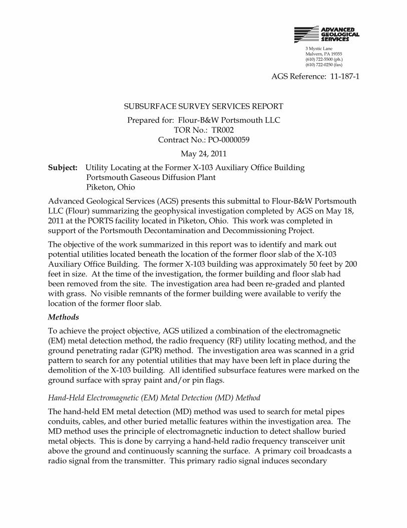
3 Mystic LaneMalvern, PA 19355(610) 722-5500 (ph.)(610) 722-0250 (fax)
AGS Reference: 11-187-1
SUBSURFACE SURVEY SERVICES REPORT
Prepared for: Flour-B&W Portsmouth LLCTOR No.: TR002
Contract No.: PO-0000059
May 24, 2011
Subject: Utility Locating at the Former X-103 Auxiliary Office BuildingPortsmouth Gaseous Diffusion PlantPiketon, Ohio
Advanced Geological Services (AGS) presents this submittal to Flour-B&W Portsmouth LLC (Flour) summarizing the geophysical investigation completed by AGS on May 18, 2011 at the PORTS facility located in Piketon, Ohio. This work was completed in support of the Portsmouth Decontamination and Decommissioning Project.
The objective of the work summarized in this report was to identify and mark out potential utilities located beneath the location of the former floor slab of the X-103 Auxiliary Office Building. The former X-103 building was approximately 50 feet by 200 feet in size. At the time of the investigation, the former building and floor slab had been removed from the site. The investigation area had been re-graded and planted with grass. No visible remnants of the former building were available to verify the location of the former floor slab.
Methods
To achieve the project objective, AGS utilized a combination of the electromagnetic (EM) metal detection method, the radio frequency (RF) utility locating method, and the ground penetrating radar (GPR) method. The investigation area was scanned in a grid pattern to search for any potential utilities that may have been left in place during the demolition of the X-103 building. All identified subsurface features were marked on the ground surface with spray paint and/or pin flags.
Hand-Held Electromagnetic (EM) Metal Detection (MD) Method
The hand-held EM metal detection (MD) method was used to search for metal pipes conduits, cables, and other buried metallic features within the investigation area. The MD method uses the principle of electromagnetic induction to detect shallow buried metal objects. This is done by carrying a hand-held radio frequency transceiver unit above the ground and continuously scanning the surface. A primary coil broadcasts a radio signal from the transmitter. This primary radio signal induces secondary
Subsurface Survey ReportMay 24, 2011AGS Ref. 11-187-1Page 2
electrical currents in metal objects. These secondary currents in turn produce a magnetic field which is detected by the receiver.
The MD instrument used for this investigation was a Fisher TW-6 pipe and cable locater. This instrument is expressly designed to detect metallic pipes, cables, USTs, manhole covers, and other buried metallic objects. The instrument produces an audible response and significant meter deflections when near a metal object. The peak instrument response occurs when the unit is directly over the object.
The TW-6 is operated in scanning mode, and does not allow for recording of the instrument response. For the present investigation, the investigation area was scanned in an approximate grid pattern to identify potential buried metallic utilities. Identified features were then marked on the ground surface with spray paint and/or pin flags.
Radio Frequency (RF) Utility Locating Methods
The investigation area was inspected using a RF utility locating system to identify and trace potential electrical, telecommunication, water, and other potential identifiable utilities.
AGS utilized a Radiodetection RD4000 utility locating instrument. This instrument consists of a receiver/tracer and a remote transmitter which operates at multiple radio-frequencies (RF) ranging from 8 kHz to 65 kHz. The receiver unit detects the transmitted RF signals as well as standard 60 Hz electrical power lines and broad-band RF signals when operated in passive detection modes. This utility tracing instrument is an analog device which provides visual and audible feedback to the operator when a utility coupled with the transmitted signal is crossed. The transmitter produces a radio-frequency signal in the utility to be traced by either induction coupling or direct hook-up. The receiver output varies an audible pitch and visual feedback depending upon how far the utility is from the receiver. By carefully adjusting the gain of the receiver it is possible to determine the location of the utility and to separate it from adjacent utilities.
The investigation area was scanned using passive 60 Hz and the broad-band RF detection modes to identify potential utilities that may be present. Direct hook-up methods were also used when possible. Identified utilities were marked on the ground surface with spray paint and/or pin flags.
Ground Penetrating Radar (GPR) Method
GPR traverses were completed in a grid pattern to identify any potential utilities within the investigation area.
A Geophysical Survey Systems SIR System 3000 GPR instrument and a 400 megahertz (MHz) antenna were used for remote sensing and imaging of subsurface features within the investigation area. The GPR method is based upon the transmission of repetitive, radio frequency electromagnetic (EM) pulses into the subsurface. When the down-going wave contacts an interface of dissimilar electrical character, it returns to the surface in the form of a reflected signal. This reflected signal is detected by a receiving transducer within the
Subsurface Survey ReportMay 24, 2011AGS Ref. 11-187-1Page 3
GPR unit and added to the data file. The GPR anomaly remains prevalent as long as the electrical contrast between media is present and constant. Any lateral or vertical changes in the electrical properties of the subsurface result in an equivalent change in the GPR signature. The system records a continuous image of the subsurface by plotting two-way travel time versus distance traveled along the ground surface. Two-way travel time values are then converted to depths using known soil velocity functions. A scan length of 60 nanoseconds (ns) was used providing a maximum depth of investigation of 10 feet below the ground surface under ideal site conditions. Very wet soil conditions, and loosely compacted clayey soil, limited GPR signal penetration to less than 2 feet below grade at this site. All identified utilities were marked on the ground surface using spray paint and/or pin flags.
Results and Discussion
The X-103 Auxiliary Office Building had been demolished, and the floor slab removed prior to the arrival of AGS on site. At the time of the investigation, the site had been regraded and planted with grass that was approximately 8 inches high. The ground surface remained irregular from heavy machinery treads and standing water was present over portions of the investigation area.
Figure 1 shows the floor plan of the former X-103 building. The locations of an active underground electrical line located parallel to the north wall of the former X-103, and the northern wall of the Electrical Components Building are also shown on Figure 1 to provide reference points with regards to the location of the former X-103 building. The active electric line shown on Figure 1 was located and marked on site with red spray paint and red pin flags.
The location of the former X-103 building and the surrounding surrounding area were scanned with using EM MD, RF, and GPR methods. The EM MD instrument identified a south to north oriented pipe located near the central portion of the former X-103 building (Figure 1). The identified pipe also has a Tee that extends westward beneath the former X-103 building. A vertical metal pipe, approximately 8 inches in diameter was observed at the southern side of former X-103, that corresponds with utility isolation point SSU-0005 shown on the original Flour base map of the X-103 floor plan (drawing no. SK-103-10-001, Rev. A).
AGS connected the RF transmitter to the pipe at isolation point SSU-0005, and traced the pipe with the RF receiver. The response from the RF instrument indicated that the pipe identified using the EM MD method was the same pipe that was directly connected to isolation point SSU-005. The location of the identified pipe was marked on site with spray paint and pink pin flags. Based on the RF response, the pipe is buried approximately 36 inches below existing grade. The location and configuration of the identified pipe is shown on Figure 1. This pipe is believed to be a former storm sewer pipe.
No additional utilities were identified beneath the former X-103 building or in the area surrounding the X-103 building. Depth penetration of the GPR signal was limited to less
Subsurface Survey ReportMay 24, 2011AGS Ref. 11-187-1Page 4
than 2 feet below grade because of existing soil and moisture conditions, as well as signal scattering caused by the irregular ground surface. Therefore, it is possible that additional utilities could exist beneath the former X-103 building that could not be detected.
In summary, one potential storm sewer pipe was detected beneath the former X-103 building, which was marked on site with spray paint and pink pin flags. No other utilities were detected using the EM MD, RF, or GPR methods. Because of the limited depth of penetration of the GPR signal, it is possible that additional abandoned utilities could be present beneath the former floor slab area that could not be detected. Upon completion of field activities, the results of the investigation were reviewed and discussed with the on site Flour representative.
Closing
All geophysical data and field notes collected as a part of this investigation will be archived at the AGS office. The data collection and interpretation methods used in this investigation are consistent with standard practices applied to similar geophysical investigations. The correlation of geophysical responses with probable subsurface features is based on the past results of similar surveys although it is possible that some variation could exist at this site. Due to the nature of geophysical data, no guarantees can be made or implied regarding the presence or absence of additional objects or targets beyond those identified.
Prepared by: Donald Jagel, P.G.Senior Geophysicist
attachment: Figure 1.
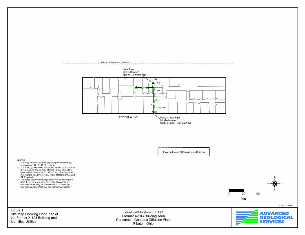
11-187-1 dj 5/23/2011
Flour-B&W Portsmouth LLCForrmer X-103 Building Area
Portsmouth Gaseous Diffusion PlantPiketon, Ohio
Figure 1Site Map Showing Floor Plan ofthe Former X-103 Building andIdentified Utilities
NOTES:1) This map was derived from the plan provided by Flour
(drawing no. SK-103-10-001, rev. A).2) The investigation area included the location of the former
X-103 building and an area at least 10 feet beyond theouter walls of the former X-103 building. The area wasinvestigated using the RF, EM metal detection (MD), andGPR methods.
3) The items shown on this figure may not be all inclusive.AGS does not warrant the fact that additional buriedfeatures/utilities may be present which could not beidentified by AGS personnel during this investigation.
Conf Room
Men
SHR
Women's RR
Existing Electrical Components Building
Former X-103
Active Underground Electric
50 ft.
35 ft.
30 ft.
Vertical Metal Pipe8-inch diameterUtility Isolation Point SSU-005
Metal Pipe(Storm Sewer?)Approx. 36 inches bgs
0 20 40
feet

DOE/PPPO/03-0223&D1
RECORD COPY DISTRIBUTION
File—FBP RMDC—RC


![The Paducah evening sun. (Paducah, KY) 1909-11-19 [p 3].nyx.uky.edu/dips/xt7hmg7fsc41/data/0989.pdf · FUIDAY NOVRSIBEn ID THE PADUCAH EVENING SUN rAo taaae Our Khowing of Sterling](https://img.pdfslide.us/doc/110x75/5f21ec80d000f51be72e83d0/the-paducah-evening-sun-paducah-ky-1909-11-19-p-3nyxukyedudipsxt7hmg7fsc41data0989pdf.jpg)
![The Paducah evening sun. (Paducah, KY) 1907-11-16 [p 3].nyx.uky.edu/dips/xt7xks6j2n2w/data/0947.pdf · 2014. 6. 24. · i f-SATURDAY NOVEMBER IliTHE PADUCAH EVENING SUN 1 h foo S](https://img.pdfslide.us/doc/110x75/60e8a69dd1e5b330a96e9605/the-paducah-evening-sun-paducah-ky-1907-11-16-p-3nyxukyedudipsxt7xks6j2n2wdata0947pdf.jpg)


![The Paducah evening sun. (Paducah, KY) 1910-10-15 [p 4].nyx.uky.edu/dips/xt7bnz80mh6f/data/0724.pdf · PlIfn THE PADUCAH EVENING SUN rUTtHDAY OCTOIlttH its + w J ... By Mall per year](https://img.pdfslide.us/doc/110x75/5b21840c7f8b9aca058b4672/the-paducah-evening-sun-paducah-ky-1910-10-15-p-4nyxukyedudipsxt7bnz80mh6fdata0724pdf.jpg)