Embed Size (px)
Citation preview
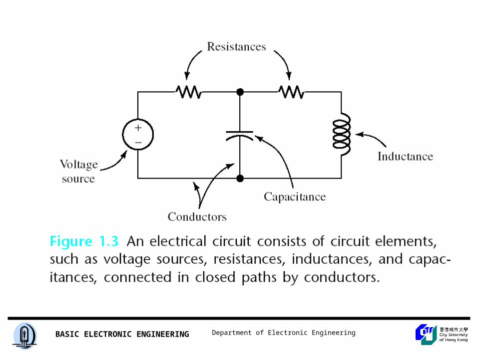
Department of Electronic EngineeringBASIC ELECTRONIC ENGINEERING
EE 2301BASIC ELECTRONIC CIRCUIT
Department of Electronic EngineeringBASIC ELECTRONIC ENGINEERING
INSTRUCTOR: DR. ANGUS WUOFFICE: G6352PHONE: 9391EMAIL: [email protected]: www.ee.cityu.edu.hk/~ee2301ID: ee2301passwd: ee2301
Department of Electronic EngineeringBASIC ELECTRONIC ENGINEERING
LECTURE 1
Department of Electronic EngineeringBASIC ELECTRONIC ENGINEERING
Fundamentals• Charge, Current, Voltage
• Ohm’s Law and Power
• Series Circuits and Kirchhoff’s Voltage Law
• Parallel Circuits and Kirchholf’s Current Law
• Resistive Circuits
• Circuit Analysis Techniques
Department of Electronic EngineeringBASIC ELECTRONIC ENGINEERING
Charge
Department of Electronic EngineeringBASIC ELECTRONIC ENGINEERING
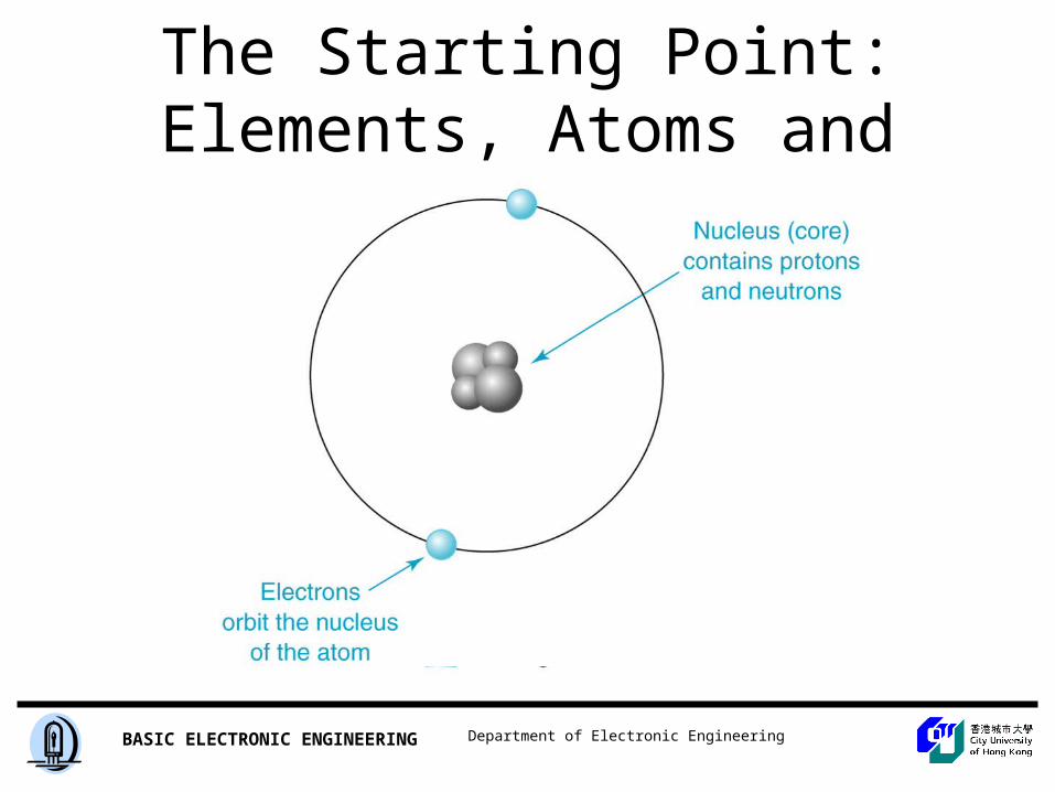
The Starting Point: Elements, Atoms and Charge
Department of Electronic EngineeringBASIC ELECTRONIC ENGINEERING
Department of Electronic EngineeringBASIC ELECTRONIC ENGINEERING
Charge
• Charge– Force that causes two particles to be attracted
to, or repelled from, each other– Two types – positive and negative– Atom – proton (positive), electron (negative),
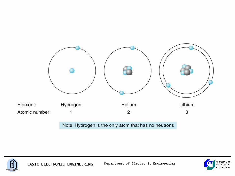
neutron (electrically neutral)
Department of Electronic EngineeringBASIC ELECTRONIC ENGINEERING
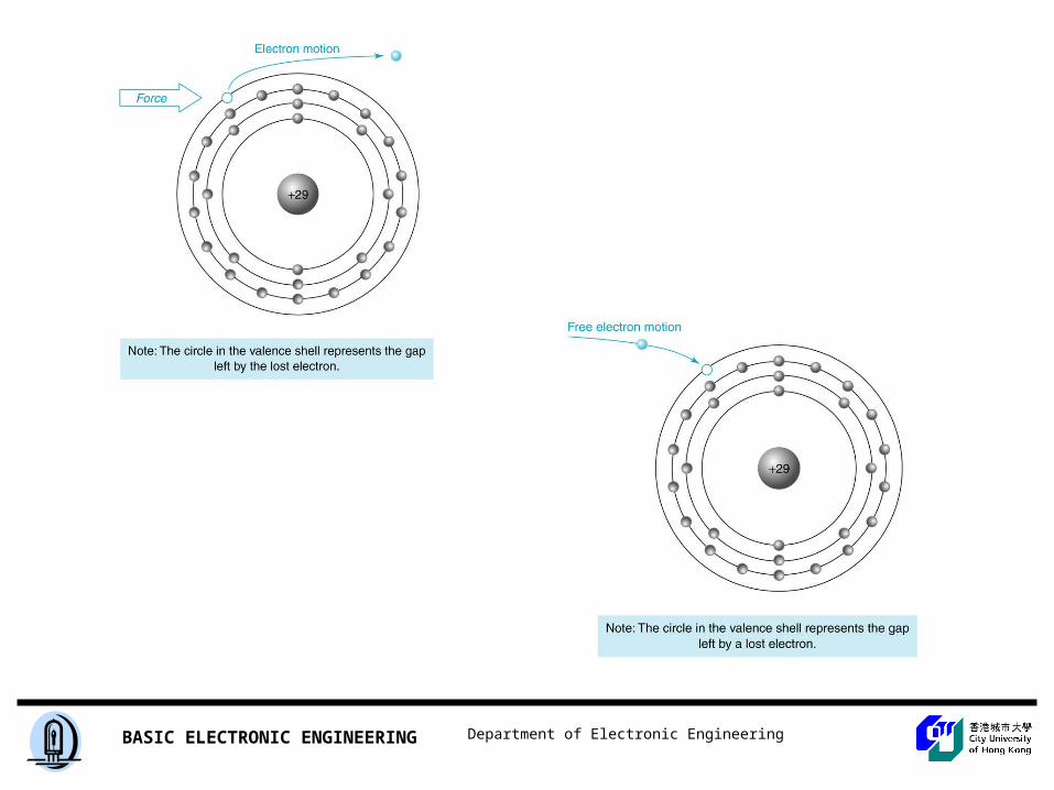
• Attraction and Repulsion - Like charges repel each other and opposite charges attract each other
• Ions– Outside force can cause an electron to leave its orbit -
atom is referred to as a positive ion– Outside force can cause an atom to gain an electron -
atom is referred to as a negative ion
• Free Electrons– An electron that is not bound to any particular atom– Can neutralize a positive ion
Department of Electronic EngineeringBASIC ELECTRONIC ENGINEERING
Department of Electronic EngineeringBASIC ELECTRONIC ENGINEERING
Current
Department of Electronic EngineeringBASIC ELECTRONIC ENGINEERING
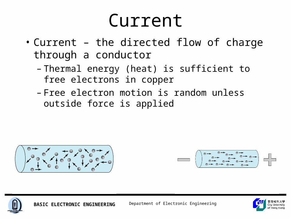
Current• Current – the directed flow of charge through a
conductor– Thermal energy (heat) is sufficient to free electrons in
copper
– Free electron motion is random unless outside force is applied
Department of Electronic EngineeringBASIC ELECTRONIC ENGINEERING
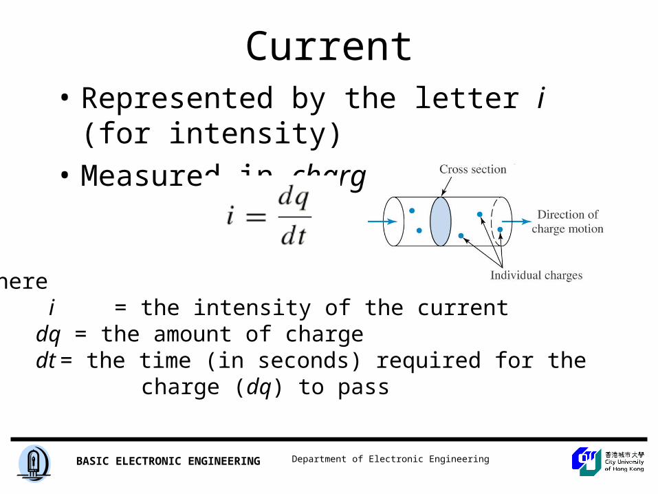
Current• Represented by the letter i (for intensity)
• Measured in charge per unit time
where i = the intensity of the currentdq = the amount of chargedt = the time (in seconds) required for the
charge (dq) to pass
Department of Electronic EngineeringBASIC ELECTRONIC ENGINEERING
Current
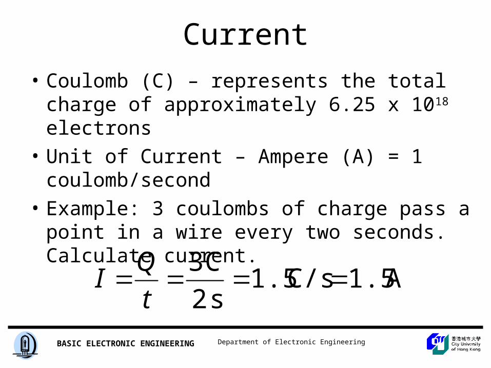
• Coulomb (C) – represents the total charge of approximately 6.25 x 10¹⁸ electrons
• Unit of Current – Ampere (A) = 1 coulomb/second
• Example: 3 coulombs of charge pass a point in a wire every two seconds. Calculate current.
A 1.5C/s 1.5s 2
C 3
t
QI
Department of Electronic EngineeringBASIC ELECTRONIC ENGINEERING
Electrical Current
Electrical current is the time rate of flow of electrical charge through a conductor or circuit element. The units are amperes (A), which are equivalent to coulombs per second (C/s).
Department of Electronic EngineeringBASIC ELECTRONIC ENGINEERING
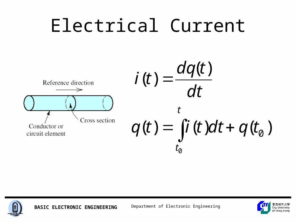
Electrical Current
t
t
tqdttitq
dt
tdqti
0
)()()(
)()(
0
Department of Electronic EngineeringBASIC ELECTRONIC ENGINEERING
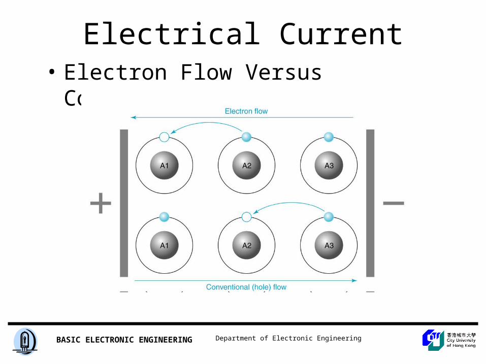
Electrical Current• Electron Flow Versus Conventional Current
Insert Figure 1.10
Department of Electronic EngineeringBASIC ELECTRONIC ENGINEERING
Department of Electronic EngineeringBASIC ELECTRONIC ENGINEERING
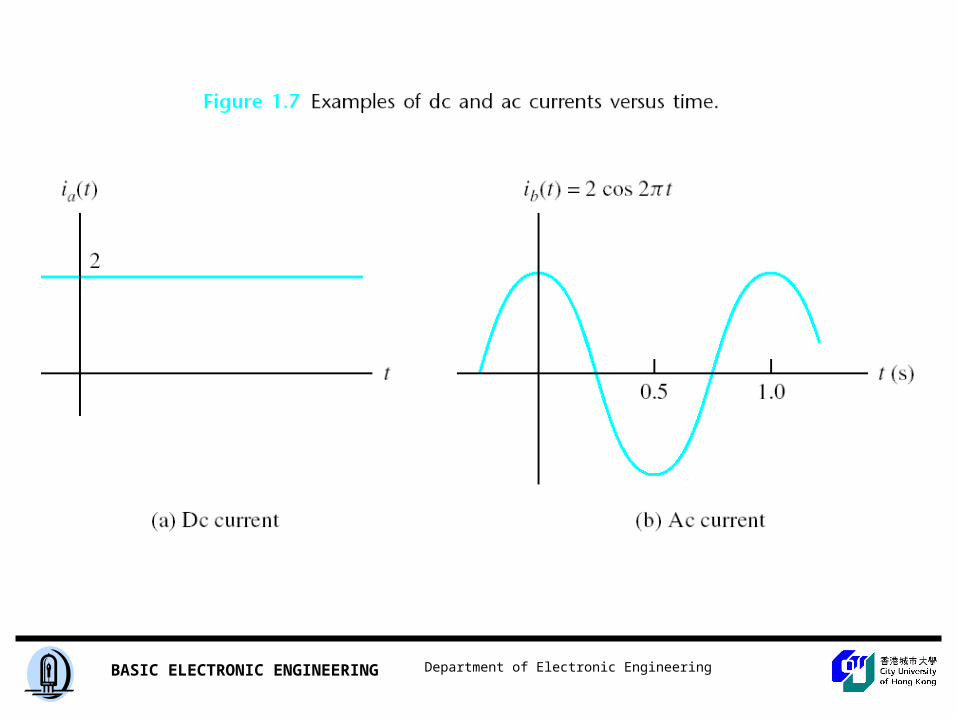
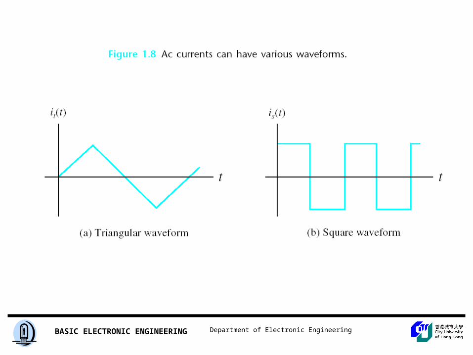
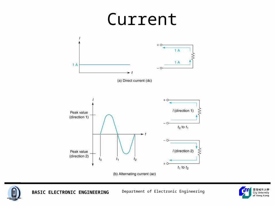
Direct Current Alternating Current
When a current is constant with time, we say that we have direct current, abbreviated as dc. On the other hand, a current that varies with time, reversing direction periodically, is called alternating current, abbreviated as ac.
Department of Electronic EngineeringBASIC ELECTRONIC ENGINEERING
Figure 4.17, 4.18
Department of Electronic EngineeringBASIC ELECTRONIC ENGINEERING
Department of Electronic EngineeringBASIC ELECTRONIC ENGINEERING
.
Department of Electronic EngineeringBASIC ELECTRONIC ENGINEERING
Department of Electronic EngineeringBASIC ELECTRONIC ENGINEERING
Department of Electronic EngineeringBASIC ELECTRONIC ENGINEERING
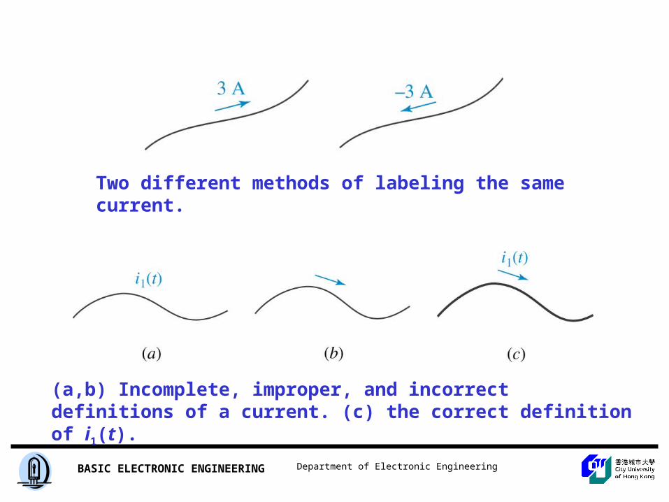
Two different methods of labeling the same current.
(a,b) Incomplete, improper, and incorrect definitions of a current. (c) the correct definition of i1(t).
Department of Electronic EngineeringBASIC ELECTRONIC ENGINEERING
Current
Insert Figure 1.11
Department of Electronic EngineeringBASIC ELECTRONIC ENGINEERING
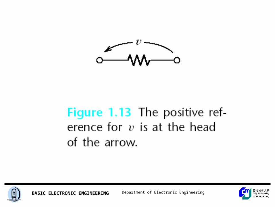
Voltage
Department of Electronic EngineeringBASIC ELECTRONIC ENGINEERING
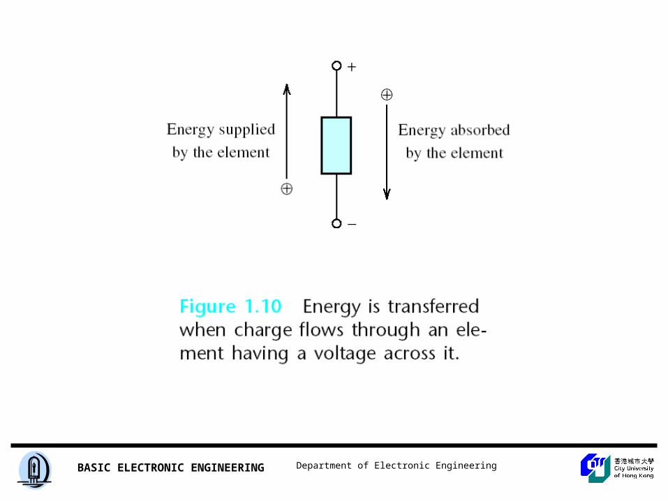
Voltage
The voltage associated with a circuit element is the energy transferred per unit of charge that flows through the element. The units of voltage are volts (V), which are equivalent to joules per coulomb (J/C).
Department of Electronic EngineeringBASIC ELECTRONIC ENGINEERING
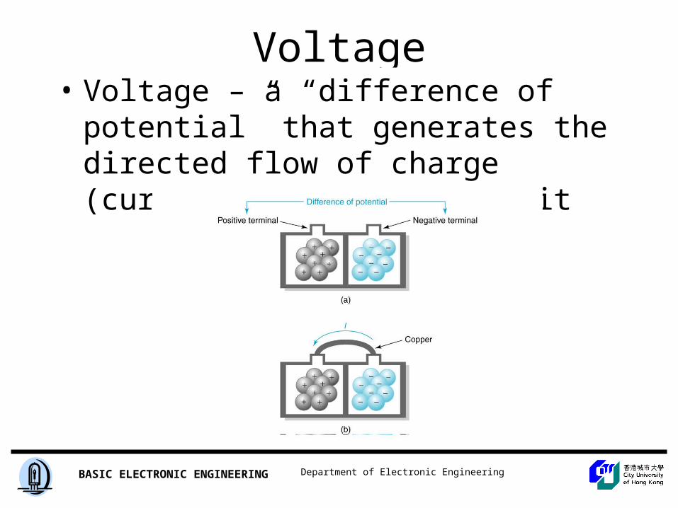
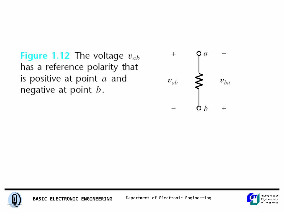
Voltage• Voltage – a “difference of potential” that
generates the directed flow of charge (current) through a circuit
Insert Figure 1.12
Department of Electronic EngineeringBASIC ELECTRONIC ENGINEERING
Department of Electronic EngineeringBASIC ELECTRONIC ENGINEERING
Voltage
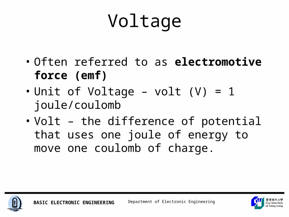
• Often referred to as electromotive force (emf)
• Unit of Voltage – volt (V) = 1 joule/coulomb
• Volt – the difference of potential that uses one joule of energy to move one coulomb of charge.
Department of Electronic EngineeringBASIC ELECTRONIC ENGINEERING
Department of Electronic EngineeringBASIC ELECTRONIC ENGINEERING
Department of Electronic EngineeringBASIC ELECTRONIC ENGINEERING
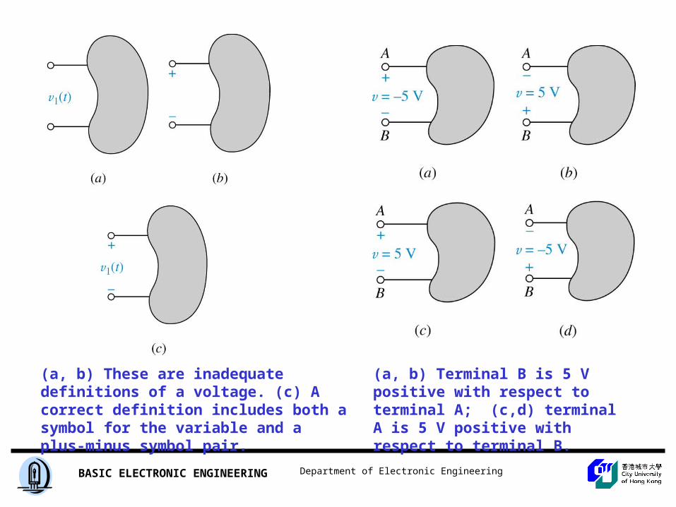
(a, b) These are inadequate definitions of a voltage. (c) A correct definition includes both a symbol for the variable and a plus-minus symbol pair.
(a, b) Terminal B is 5 V positive with respect to terminal A; (c,d) terminal A is 5 V positive with respect to terminal B.
Department of Electronic EngineeringBASIC ELECTRONIC ENGINEERING
Department of Electronic EngineeringBASIC ELECTRONIC ENGINEERING
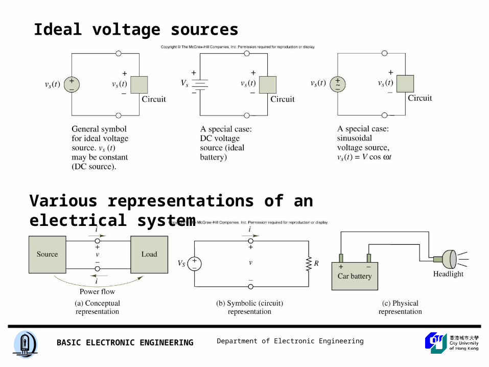
Ideal voltage sources
Various representations of an electrical system
Department of Electronic EngineeringBASIC ELECTRONIC ENGINEERING
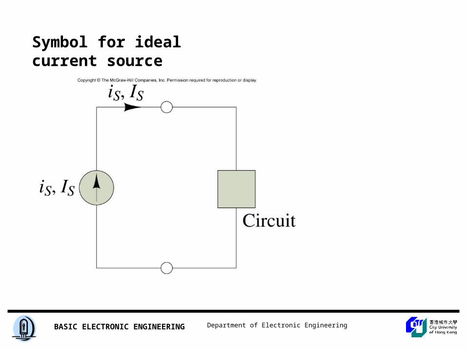
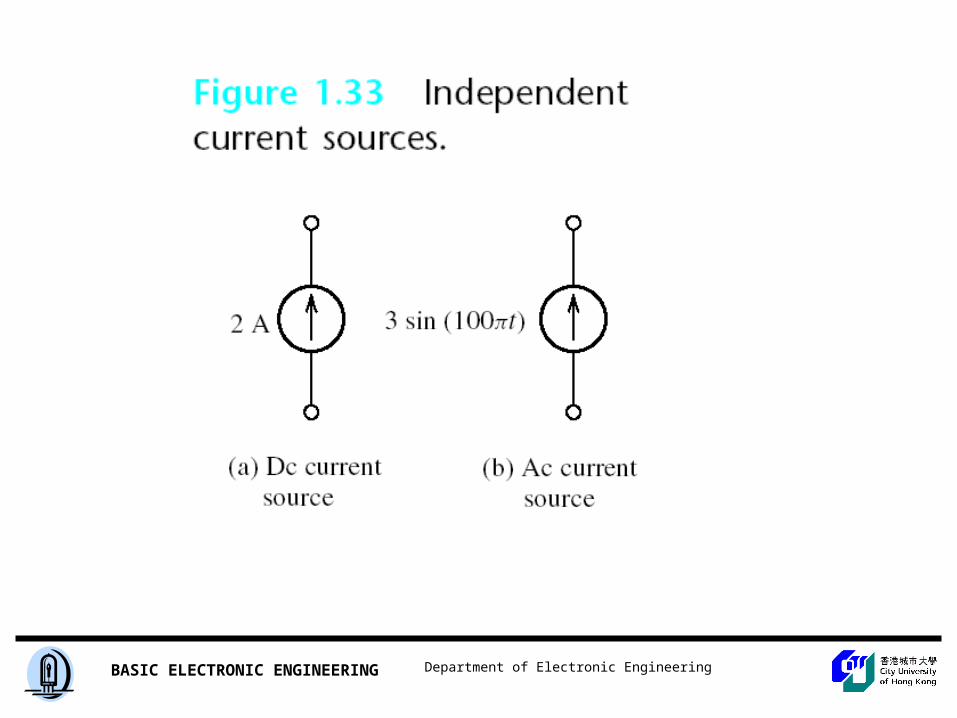
Symbol for ideal current source
Department of Electronic EngineeringBASIC ELECTRONIC ENGINEERING
Ohm’s Law and Power
Department of Electronic EngineeringBASIC ELECTRONIC ENGINEERING
Ohm’s Law• German Physicist – George Simon Ohm
– Found that current is inversely proportional to resistance for a given voltage– Known as Ohm’s law
• The Relationship Between Current and Voltage• The Relationship Between Current and Resistance
Department of Electronic EngineeringBASIC ELECTRONIC ENGINEERING
Basic Circuit Calculations
• Using Ohm’s Law to Calculate Current
where R = the circuit resistanceV = the applied voltage
R
VI
Department of Electronic EngineeringBASIC ELECTRONIC ENGINEERING
Basic Circuit Calculations
• Using Ohm’s Law to Calculate Voltage
where I = the circuit currentR = the circuit resistance
IRV
Department of Electronic EngineeringBASIC ELECTRONIC ENGINEERING
Basic Circuit Calculations
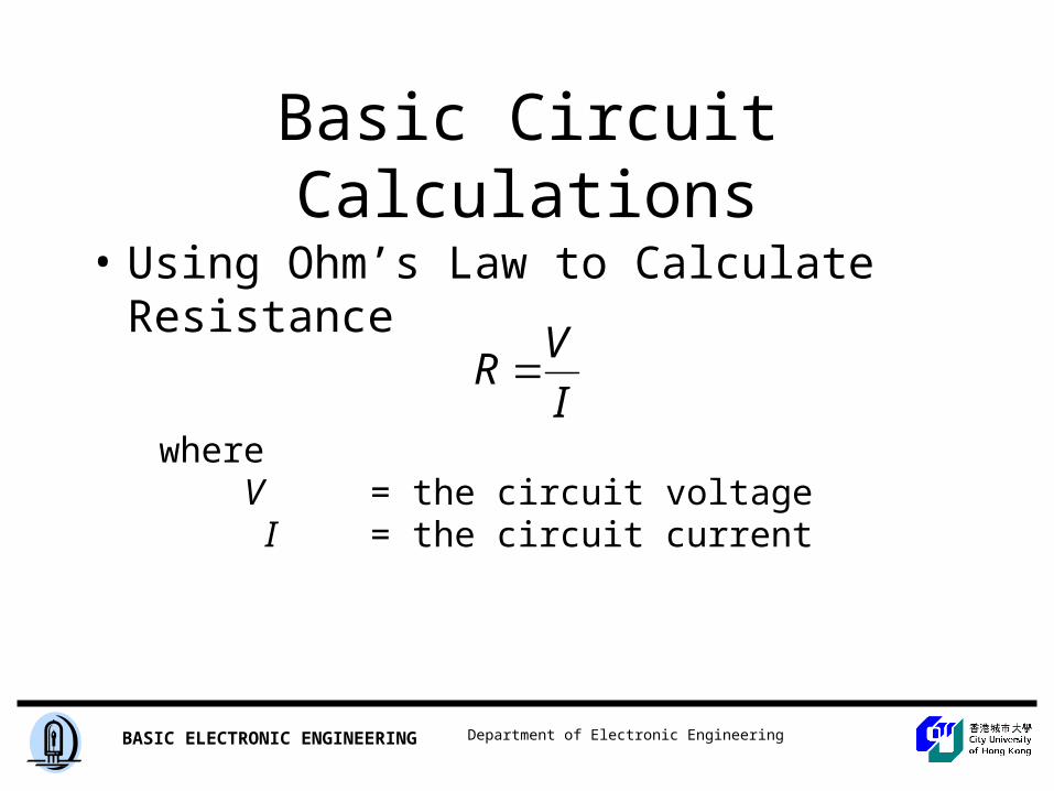
• Using Ohm’s Law to Calculate Resistance
whereV = the circuit voltage I = the circuit current
I
VR
Department of Electronic EngineeringBASIC ELECTRONIC ENGINEERING
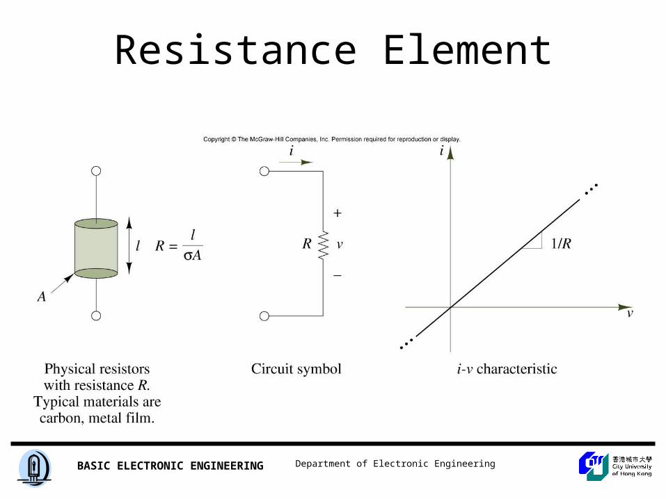
Resistance Element
Department of Electronic EngineeringBASIC ELECTRONIC ENGINEERING
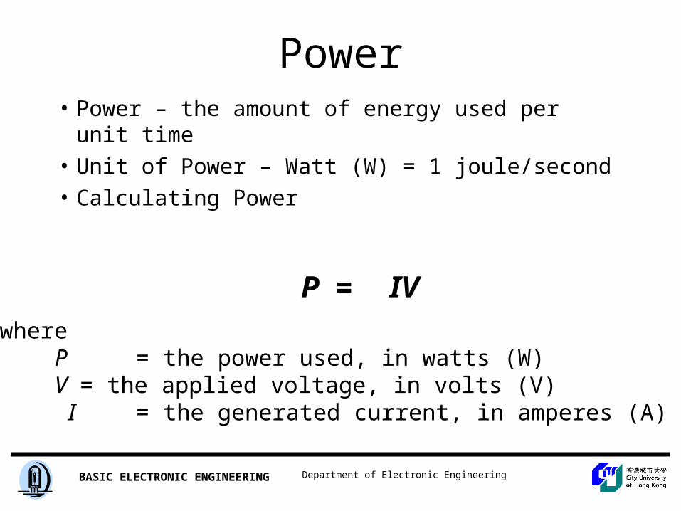
Power• Power – the amount of energy used per unit time
• Unit of Power – Watt (W) = 1 joule/second
• Calculating Power
whereP = the power used, in watts (W)V = the applied voltage, in volts (V) I = the generated current, in amperes (A)
P = IV
Department of Electronic EngineeringBASIC ELECTRONIC ENGINEERING
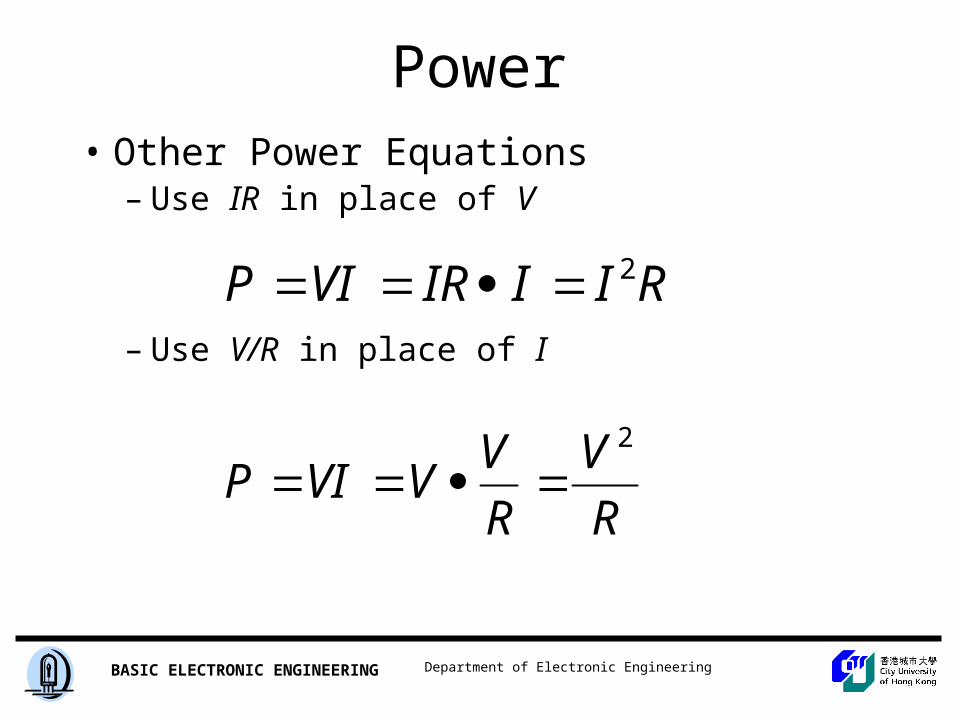
Power• Other Power Equations
– Use IR in place of V
– Use V/R in place of I
RIIIRVIP 2
R
V
R
VVVIP
2
Department of Electronic EngineeringBASIC ELECTRONIC ENGINEERING
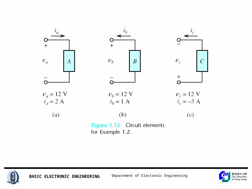
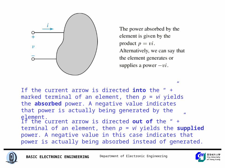
If the current arrow is directed into the “ +” marked terminal of an element, then p = vi yields the absorbed power. A negative value indicates that power is actually being generated by the element.
If the current arrow is directed out of the “ +” terminal of an element, then p = vi yields the supplied power. A negative value in this case indicates that power is actually being absorbed instead of generated.
Department of Electronic EngineeringBASIC ELECTRONIC ENGINEERING
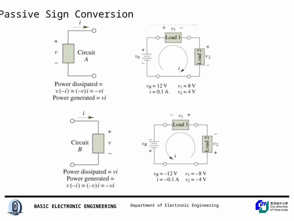
Passive Sign Conversion
Department of Electronic EngineeringBASIC ELECTRONIC ENGINEERING
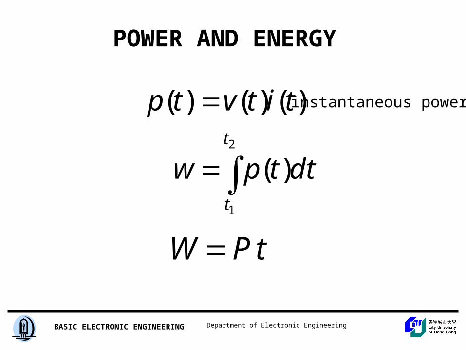
POWER AND ENERGY
2
1
)(
)()()(t
t
dttpw
titvtp
tPW
instantaneous power
Department of Electronic EngineeringBASIC ELECTRONIC ENGINEERING
Power
• Power and Heat– Resistors and other components convert energy
to heat (transducer)– If power rating is exceeded, the component will
keep getting hotter and be destroyed– Common guideline – select a component with
twice the required power-dissipation capability
Department of Electronic EngineeringBASIC ELECTRONIC ENGINEERING
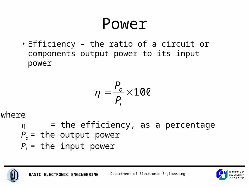
Power• Efficiency – the ratio of a circuit or
components output power to its input power
where = the efficiency, as a percentagePo = the output powerPi = the input power
100i
o
P
P
Department of Electronic EngineeringBASIC ELECTRONIC ENGINEERING
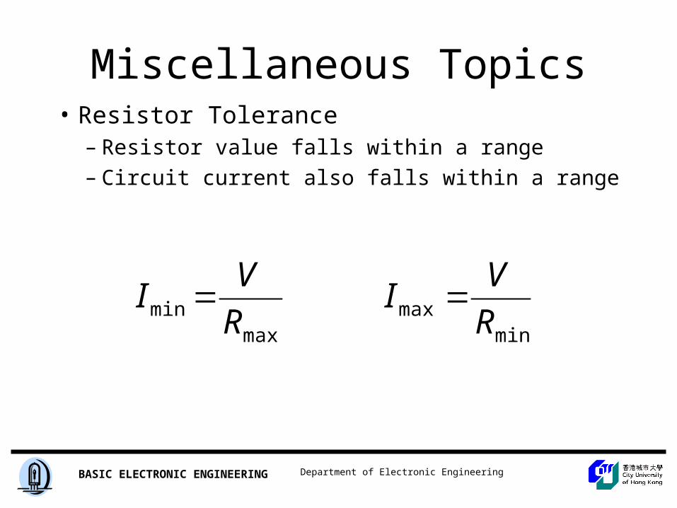
Miscellaneous Topics• Resistor Tolerance
– Resistor value falls within a range– Circuit current also falls within a range
maxmin R
VI
minmax R
VI
Department of Electronic EngineeringBASIC ELECTRONIC ENGINEERING
Miscellaneous Topics
• Circuit Loads– Source – supplies the power– Load – absorbs (uses) the power– Full Load – one that draws the maximum
current
Department of Electronic EngineeringBASIC ELECTRONIC ENGINEERING
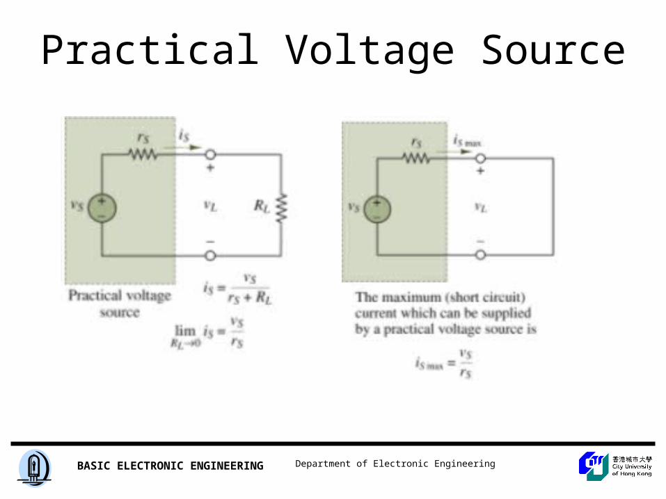
Practical Voltage Source
Department of Electronic EngineeringBASIC ELECTRONIC ENGINEERING
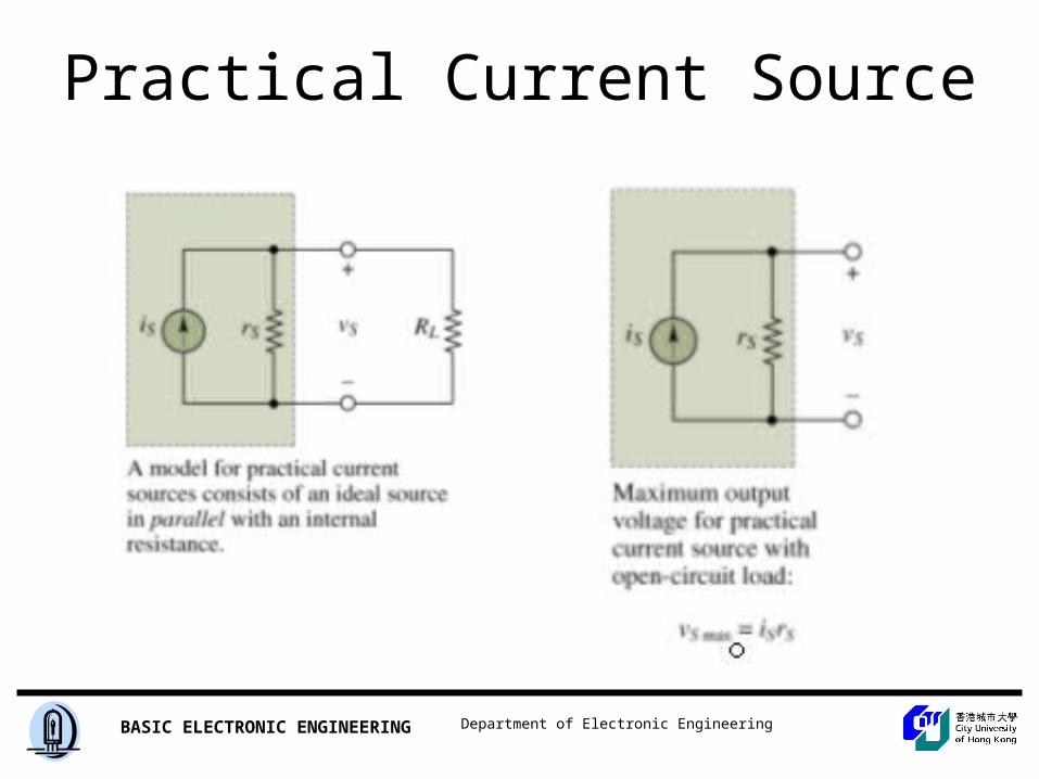
Practical Current Source
Department of Electronic EngineeringBASIC ELECTRONIC ENGINEERING
Circuit Topology Fundamental
Department of Electronic EngineeringBASIC ELECTRONIC ENGINEERING
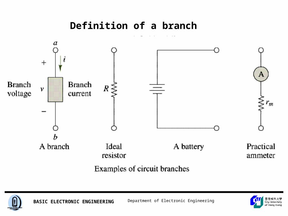
Definition of a branch
Department of Electronic EngineeringBASIC ELECTRONIC ENGINEERING
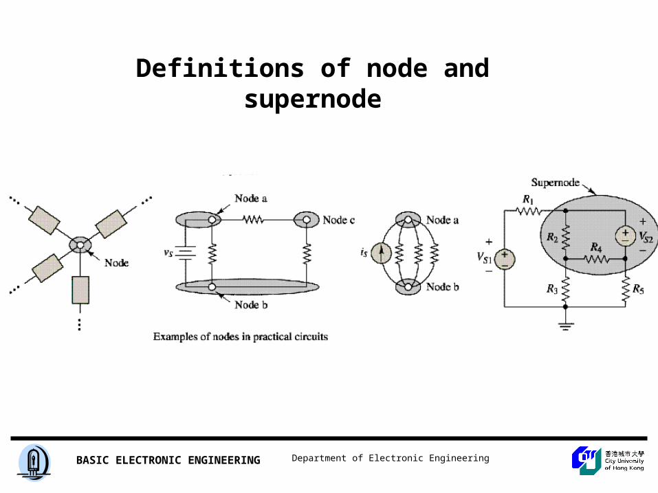
Definitions of node and supernode
Department of Electronic EngineeringBASIC ELECTRONIC ENGINEERING
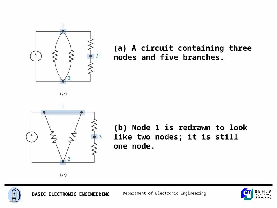
(a) A circuit containing three nodes and five branches.
(b) Node 1 is redrawn to look like two nodes; it is still one node.
Department of Electronic EngineeringBASIC ELECTRONIC ENGINEERING
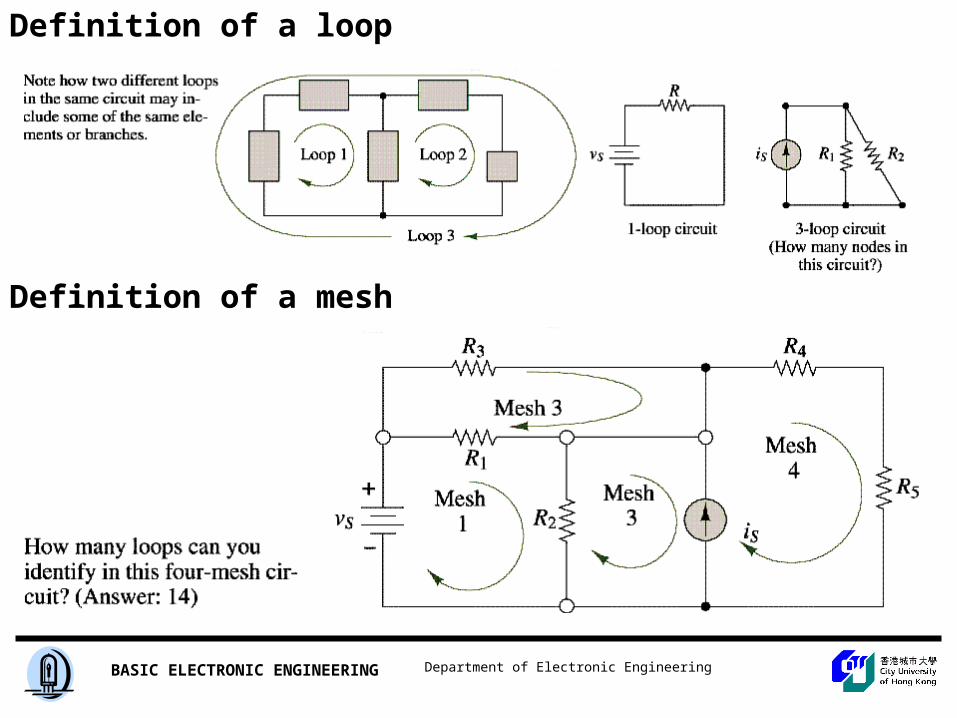
Definition of a loop
Definition of a mesh
Department of Electronic EngineeringBASIC ELECTRONIC ENGINEERING
Series Circuits and
Kirchhoff’s Voltage Law
Department of Electronic EngineeringBASIC ELECTRONIC ENGINEERING
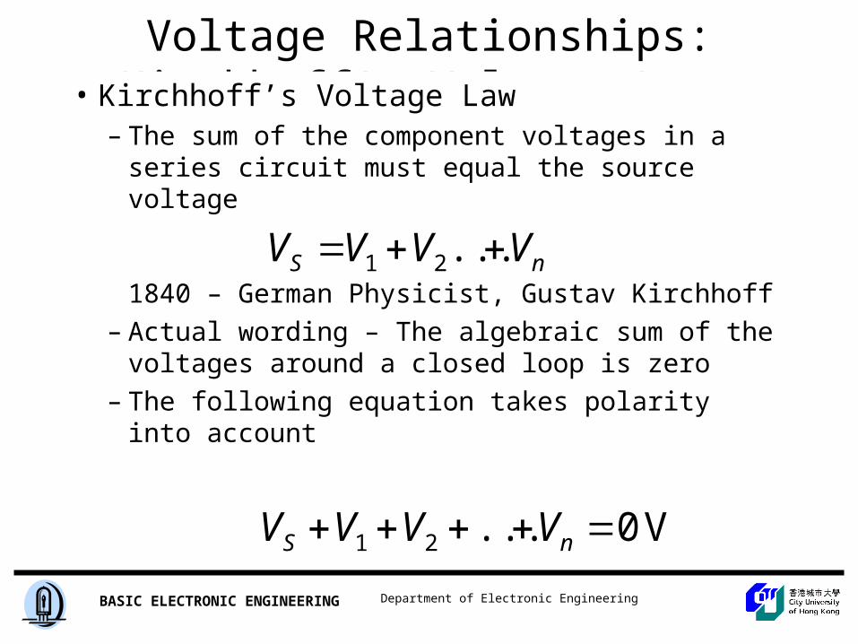
Voltage Relationships: Kirchhoff’s Voltage Law • Kirchhoff’s Voltage Law
– The sum of the component voltages in a series circuit must equal the source voltage
1840 – German Physicist, Gustav Kirchhoff
– Actual wording – The algebraic sum of the voltages around a closed loop is zero
– The following equation takes polarity into account
nS VVVV ...21
V 0...21 nS VVVV
Department of Electronic EngineeringBASIC ELECTRONIC ENGINEERING
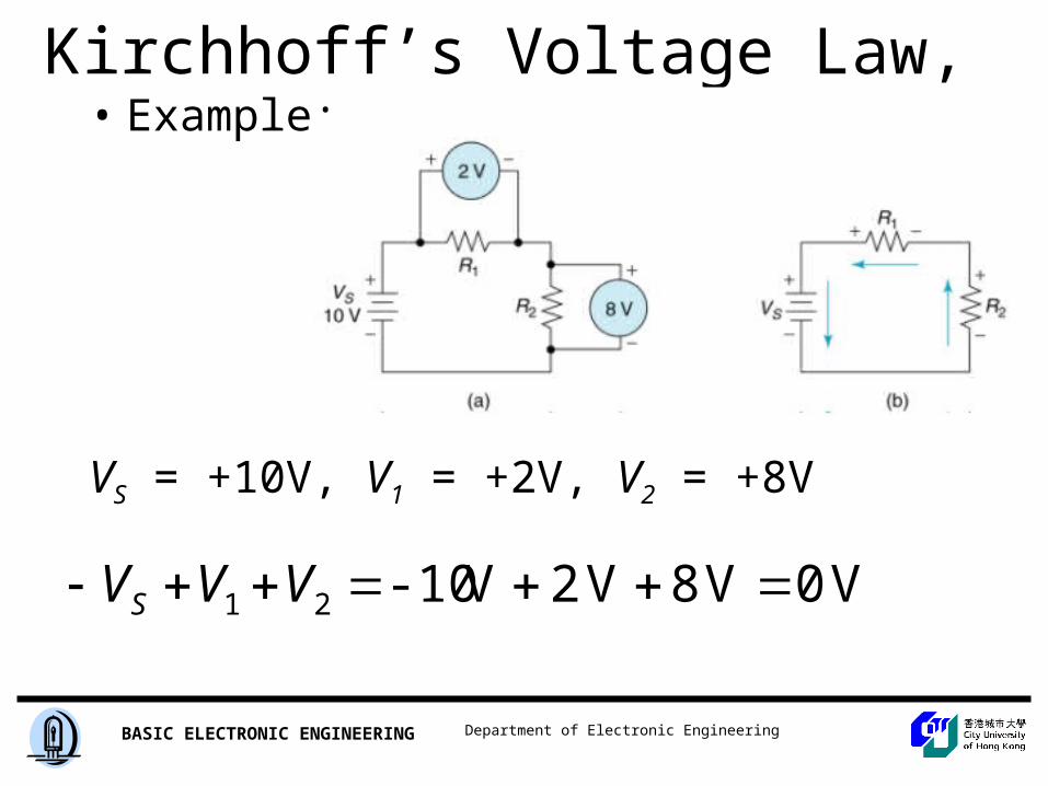
Kirchhoff’s Voltage Law, • Example:
VS = +10V, V1 = +2V, V2 = +8V
V 0V 8V 2V -1021 VVVS
Department of Electronic EngineeringBASIC ELECTRONIC ENGINEERING
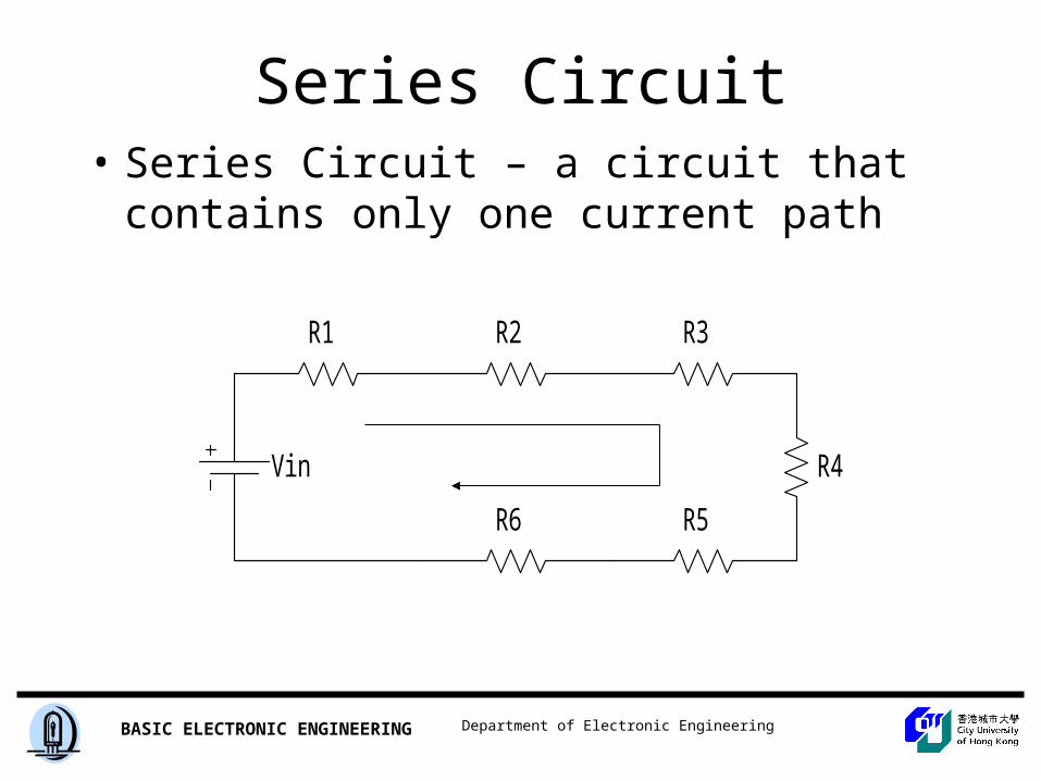
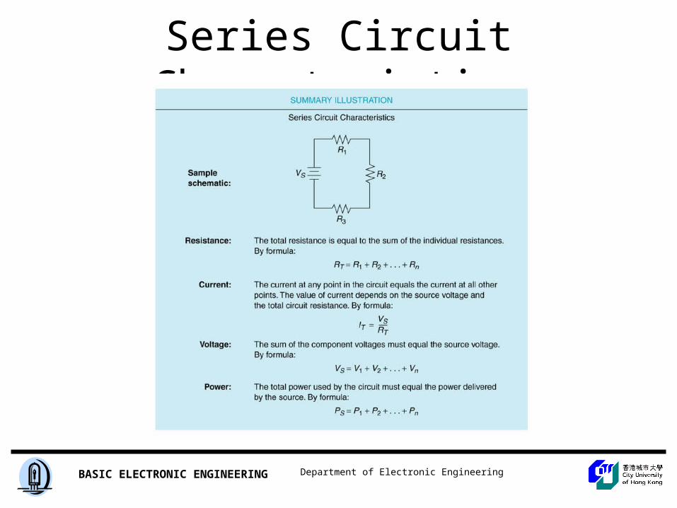
Series Circuit Characteristics• Series Circuit – a circuit that contains only
one current path
Vin
R5
R4
R6
R3R2R1
Department of Electronic EngineeringBASIC ELECTRONIC ENGINEERING
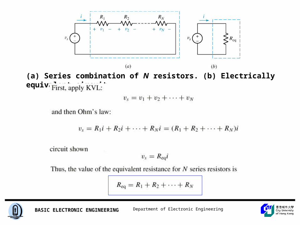
(a) Series combination of N resistors. (b) Electrically equivalent circuit.
Department of Electronic EngineeringBASIC ELECTRONIC ENGINEERING
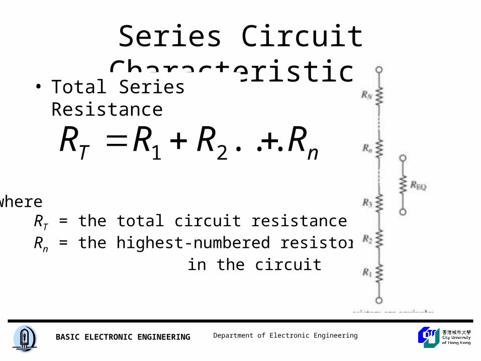
Series Circuit Characteristics
• Total Series Resistance
whereRT = the total circuit resistanceRn = the highest-numbered resistor
in the circuit
nT RRRR ...21
Department of Electronic EngineeringBASIC ELECTRONIC ENGINEERING
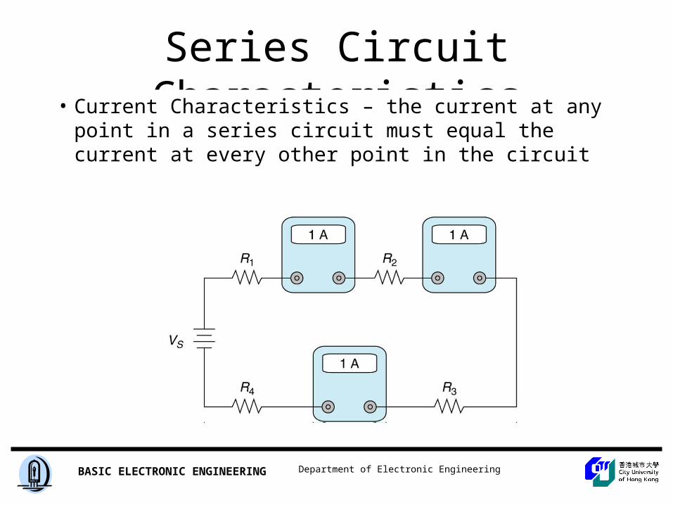
Series Circuit Characteristics• Current Characteristics – the current at any point
in a series circuit must equal the current at every other point in the circuit
Insert Figure 4.5
Department of Electronic EngineeringBASIC ELECTRONIC ENGINEERING
Series Circuit Characteristics
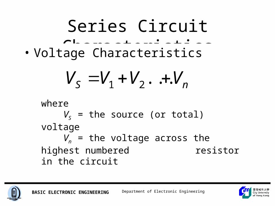
• Voltage Characteristics
whereVS = the source (or total) voltageVn = the voltage across the highest numbered
resistor in the circuit
nS VVVV ...21
Department of Electronic EngineeringBASIC ELECTRONIC ENGINEERING
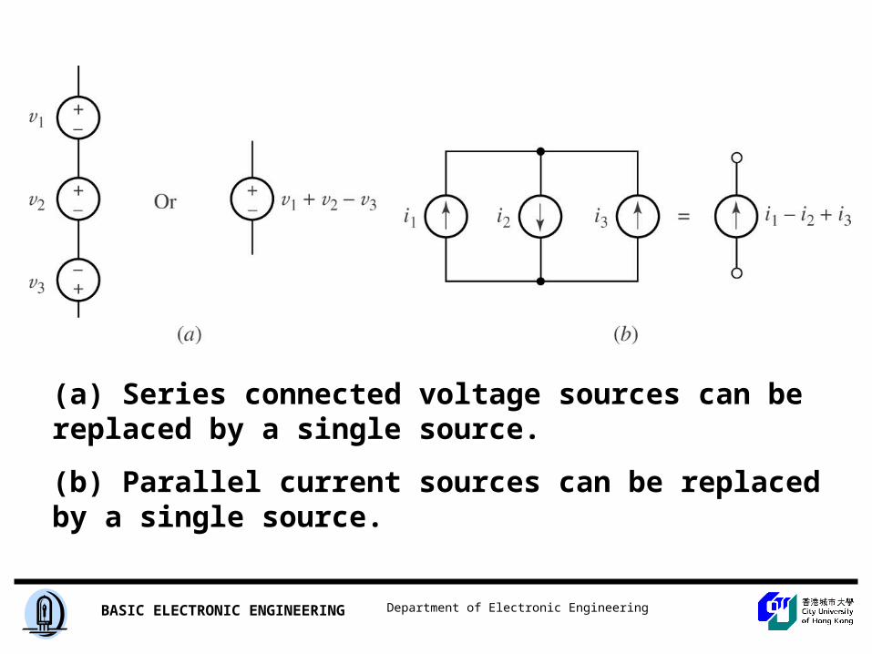
(a) Series connected voltage sources can be replaced by a single source.
(b) Parallel current sources can be replaced by a single source.
Department of Electronic EngineeringBASIC ELECTRONIC ENGINEERING
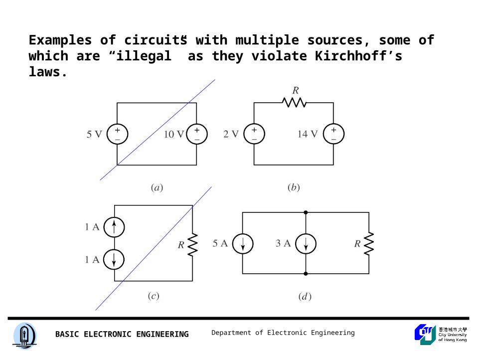
Examples of circuits with multiple sources, some of which are “illegal” as they violate Kirchhoff’s laws.
Department of Electronic EngineeringBASIC ELECTRONIC ENGINEERING
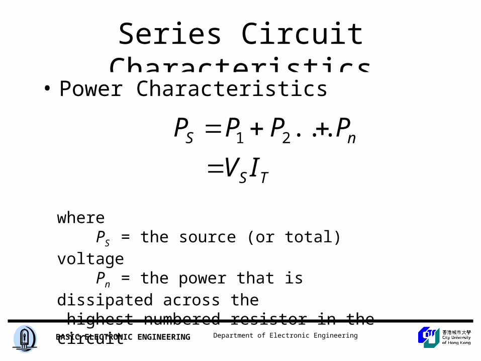
Series Circuit Characteristics
• Power Characteristics
wherePS = the source (or total) voltagePn = the power that is dissipated across the
highest numbered resistor in the circuit
TS
nS
IV
PPPP
...21
Department of Electronic EngineeringBASIC ELECTRONIC ENGINEERING
Series Circuit Characteristics
Insert Figure 4.10
Department of Electronic EngineeringBASIC ELECTRONIC ENGINEERING
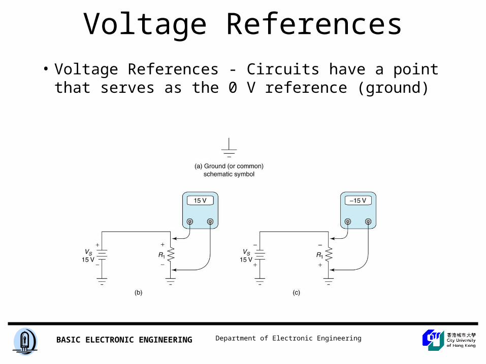
Voltage References
• Voltage References - Circuits have a point that serves as the 0 V reference (ground)
Insert Figure 4.12
Department of Electronic EngineeringBASIC ELECTRONIC ENGINEERING
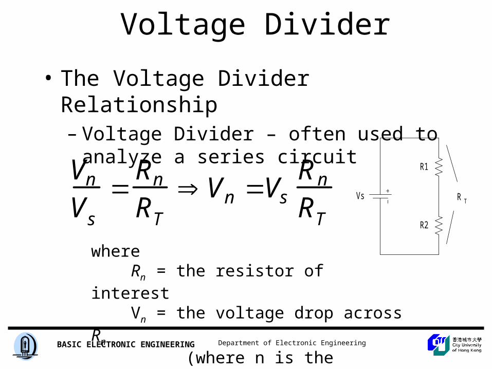
Voltage Divider
• The Voltage Divider Relationship– Voltage Divider – often used to analyze a series
circuit
Vn
Vs
Rn
RT
Vn VsRn
RT
whereRn = the resistor of interestVn = the voltage drop across Rn
(where n is the component number)
Vs
R1
R2
R T
Department of Electronic EngineeringBASIC ELECTRONIC ENGINEERING
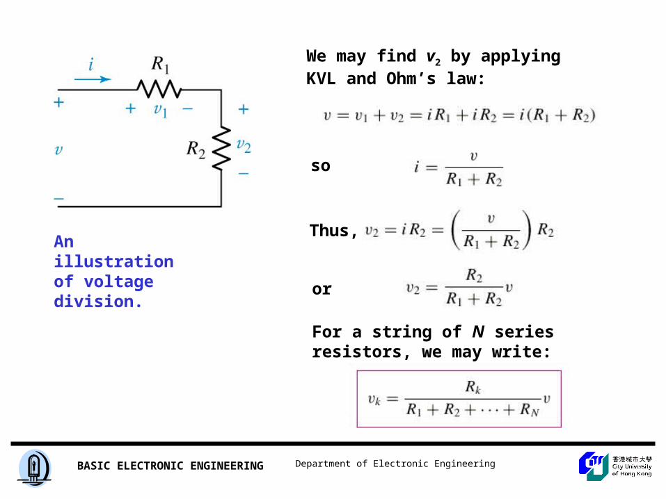
An illustration of voltage division.
We may find v2 by applying KVL and Ohm’s law:
so
Thus,
or
For a string of N series resistors, we may write:
Department of Electronic EngineeringBASIC ELECTRONIC ENGINEERING
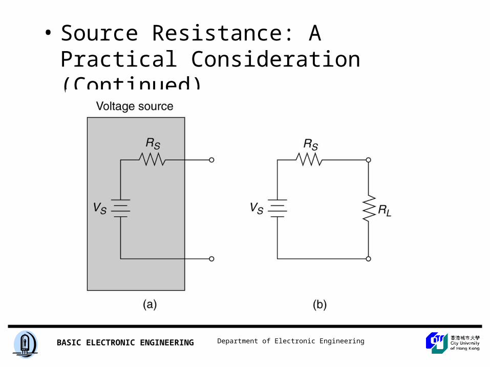
• Source Resistance: A Practical Consideration– Ideal Voltage Source – maintains a constant output voltage
regardless of the resistance of its load– Real Voltage Source – internal resistance causes a decrease
in load resistance results in a decrease in the source voltage
Department of Electronic EngineeringBASIC ELECTRONIC ENGINEERING
Insert Figure 4.20
• Source Resistance: A Practical Consideration (Continued)
Department of Electronic EngineeringBASIC ELECTRONIC ENGINEERING
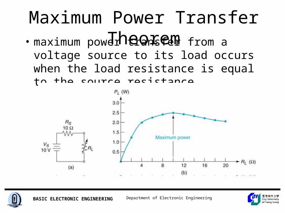
Maximum Power Transfer Theorem• maximum power transfer from a voltage
source to its load occurs when the load resistance is equal to the source resistance
Department of Electronic EngineeringBASIC ELECTRONIC ENGINEERING
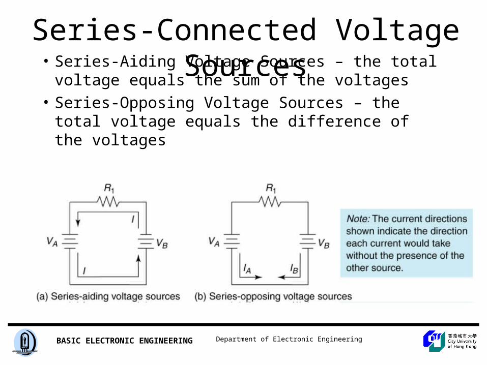
Series-Connected Voltage Sources• Series-Aiding Voltage Sources – the total
voltage equals the sum of the voltages
• Series-Opposing Voltage Sources – the total voltage equals the difference of the voltages
Department of Electronic EngineeringBASIC ELECTRONIC ENGINEERING
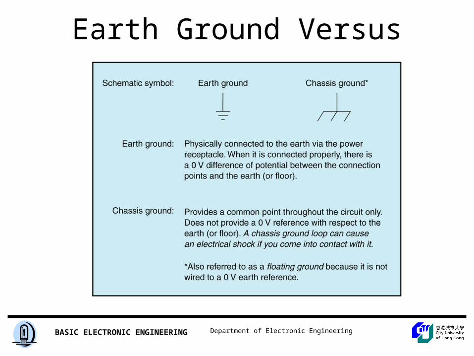
Earth Ground Versus Chassis Ground
Insert Figure 4.28
Department of Electronic EngineeringBASIC ELECTRONIC ENGINEERING
Parallel Circuitsand
Kirchholf’s Current Law
Department of Electronic EngineeringBASIC ELECTRONIC ENGINEERING
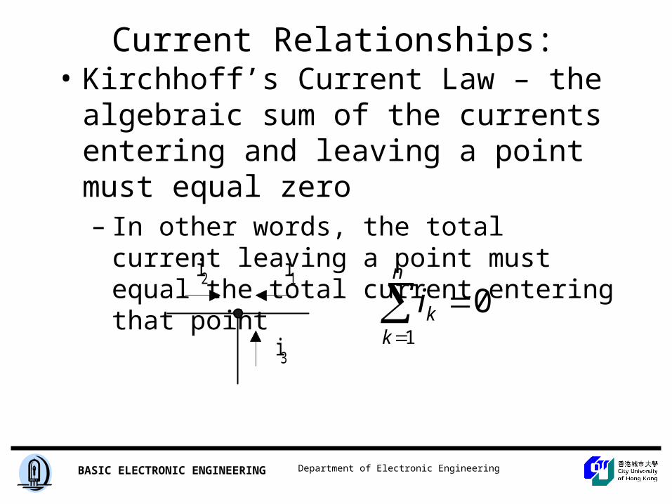
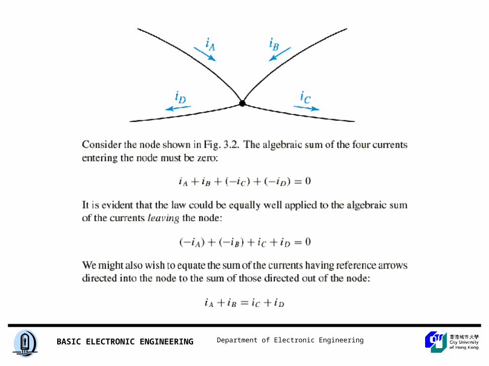
Current Relationships: Kirchhoff’s Current Law• Kirchhoff’s Current Law – the algebraic
sum of the currents entering and leaving a point must equal zero– In other words, the total current leaving a point
must equal the total current entering that point
i1i2
i3
01
n
kki
Department of Electronic EngineeringBASIC ELECTRONIC ENGINEERING
Department of Electronic EngineeringBASIC ELECTRONIC ENGINEERING
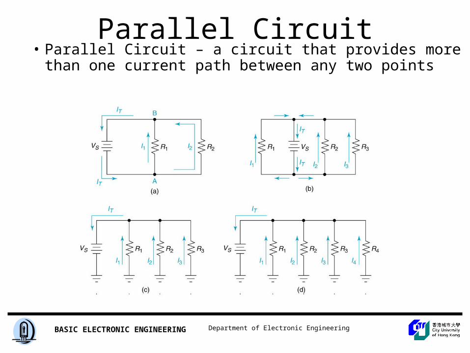
Parallel Circuit Characteristics• Parallel Circuit – a circuit that provides more
than one current path between any two points
Insert Figure 5.1
Department of Electronic EngineeringBASIC ELECTRONIC ENGINEERING
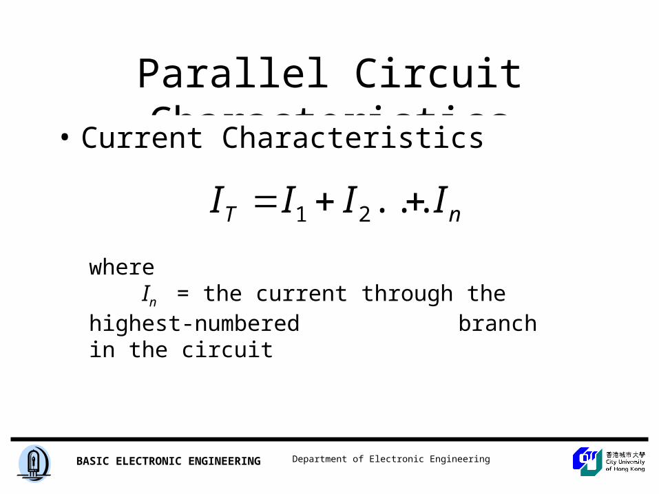
Parallel Circuit Characteristics
• Current Characteristics
whereIn = the current through the highest-numbered
branch in the circuit
nT IIII ...21
Department of Electronic EngineeringBASIC ELECTRONIC ENGINEERING
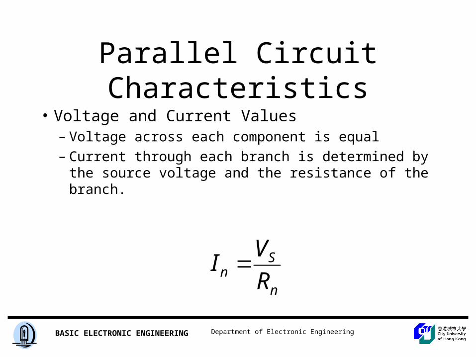
Parallel Circuit Characteristics
• Voltage and Current Values– Voltage across each component is equal
– Current through each branch is determined by the source voltage and the resistance of the branch.
n
Sn R
VI
Department of Electronic EngineeringBASIC ELECTRONIC ENGINEERING
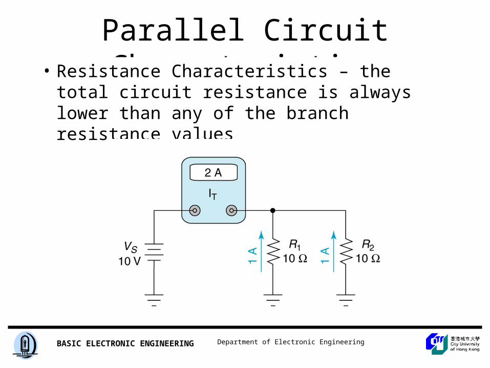
Parallel Circuit Characteristics• Resistance Characteristics – the total circuit
resistance is always lower than any of the branch resistance values
Insert Figure 5.5
Department of Electronic EngineeringBASIC ELECTRONIC ENGINEERING
Parallel Circuit Characteristics
• Power Characteristics– Total Power – sum of the power dissipation values for
the individual components– The lower value of the branch resistance, the higher
percentage of the total power it dissipates (opposite that of series circuits)
Department of Electronic EngineeringBASIC ELECTRONIC ENGINEERING
Parallel Circuit Characteristics
Insert Figure 5.6
Department of Electronic EngineeringBASIC ELECTRONIC ENGINEERING
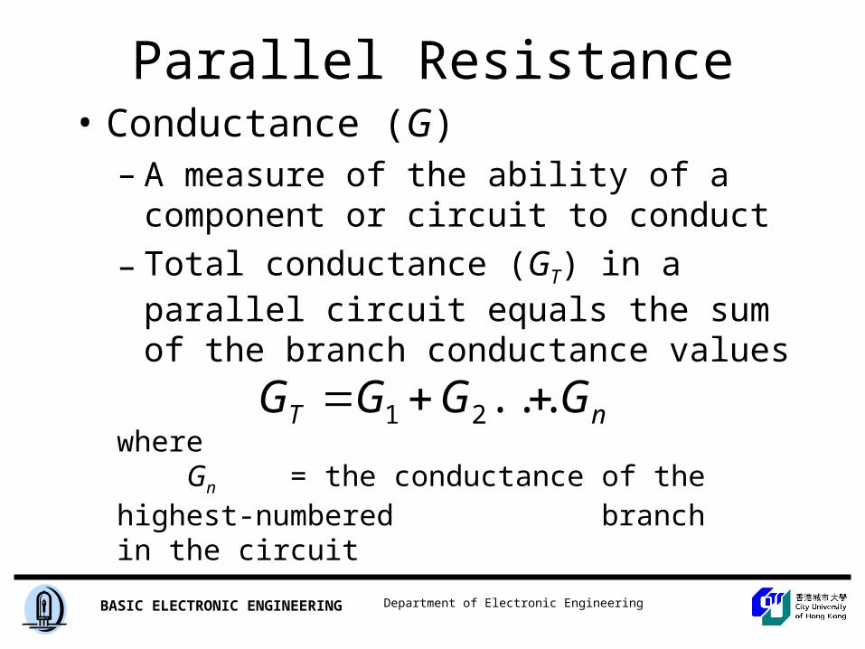
Parallel Resistance Relationships• Conductance (G)
– A measure of the ability of a component or circuit to conduct
– Total conductance (GT) in a parallel circuit equals the sum of the branch conductance values
whereGn = the conductance of the highest-numbered
branch in the circuit
nT GGGG ...21
Department of Electronic EngineeringBASIC ELECTRONIC ENGINEERING
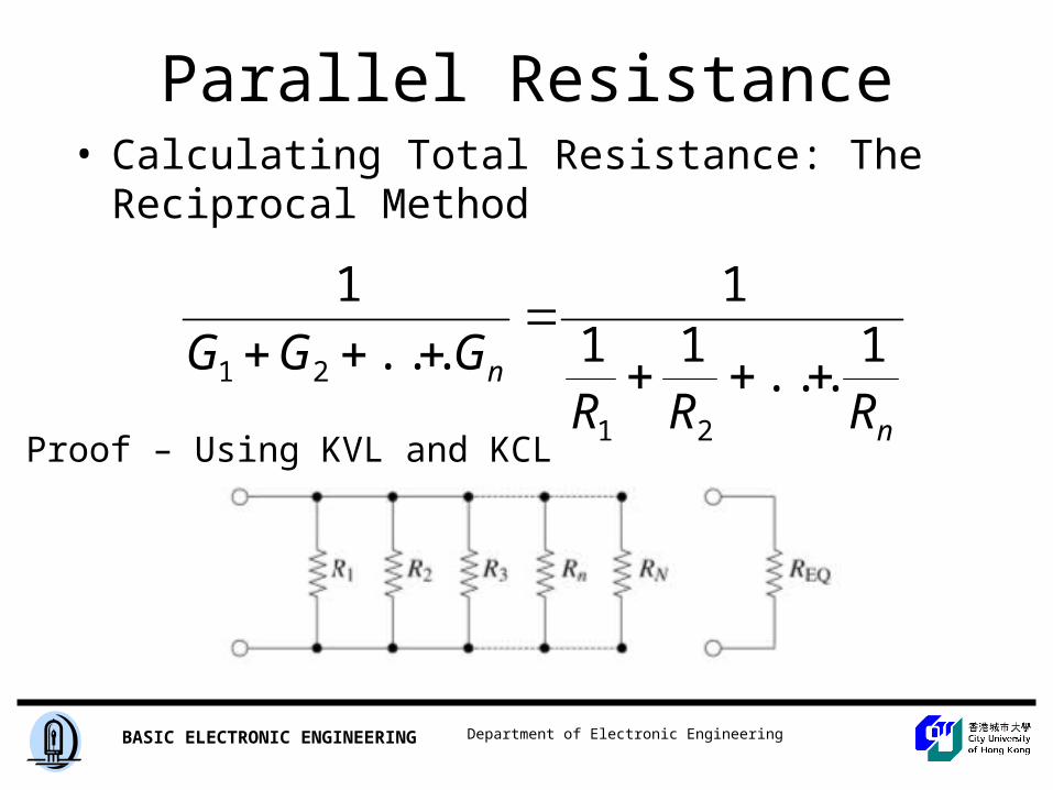
Parallel Resistance Relationships• Calculating Total Resistance: The Reciprocal
Method
n
n
RRRGGG 1
...11
1
...
1
21
21
Proof – Using KVL and KCL
Department of Electronic EngineeringBASIC ELECTRONIC ENGINEERING
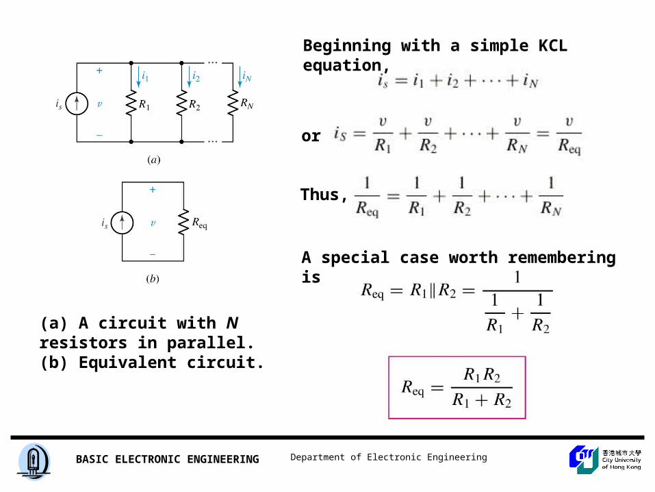
(a) A circuit with N resistors in parallel. (b) Equivalent circuit.
Beginning with a simple KCL equation,
or
Thus,
A special case worth remembering is
Department of Electronic EngineeringBASIC ELECTRONIC ENGINEERING
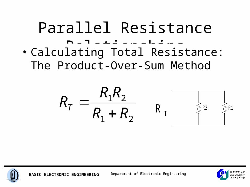
Parallel Resistance Relationships
• Calculating Total Resistance: The Product-Over-Sum Method
21
21
RR
RRRT
R2 R1R T
Department of Electronic EngineeringBASIC ELECTRONIC ENGINEERING
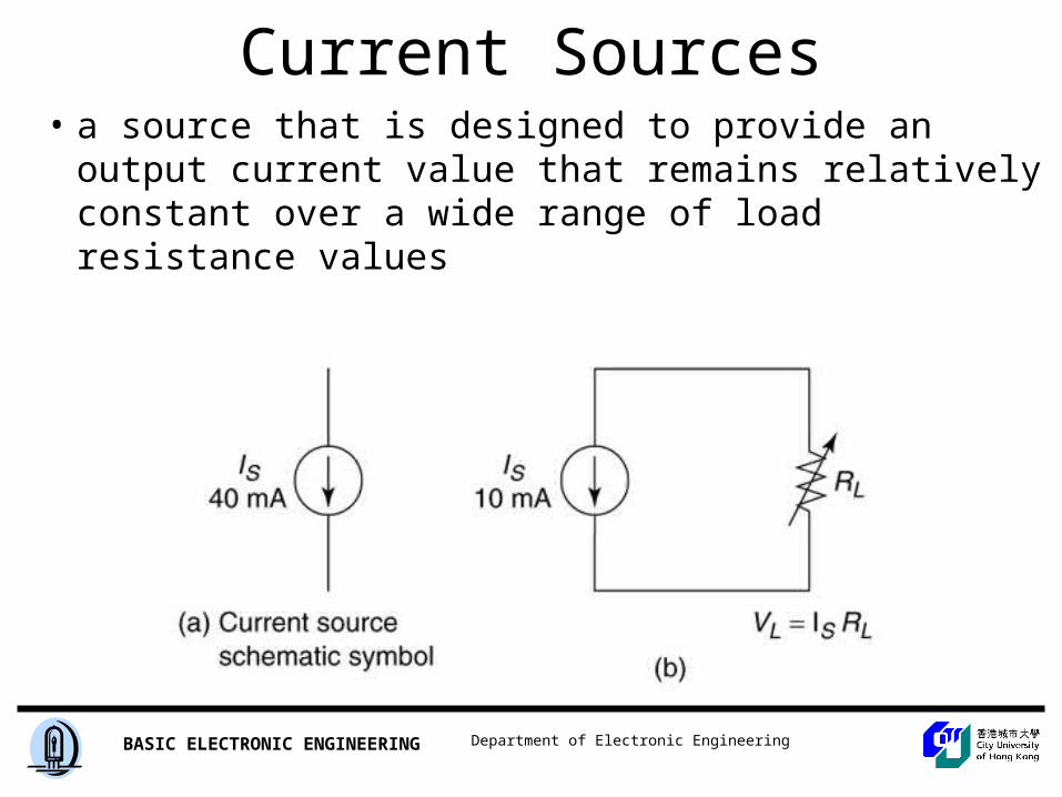
Current Sources• a source that is designed to provide an output
current value that remains relatively constant over a wide range of load resistance values
Insert Figure 5.12
Department of Electronic EngineeringBASIC ELECTRONIC ENGINEERING
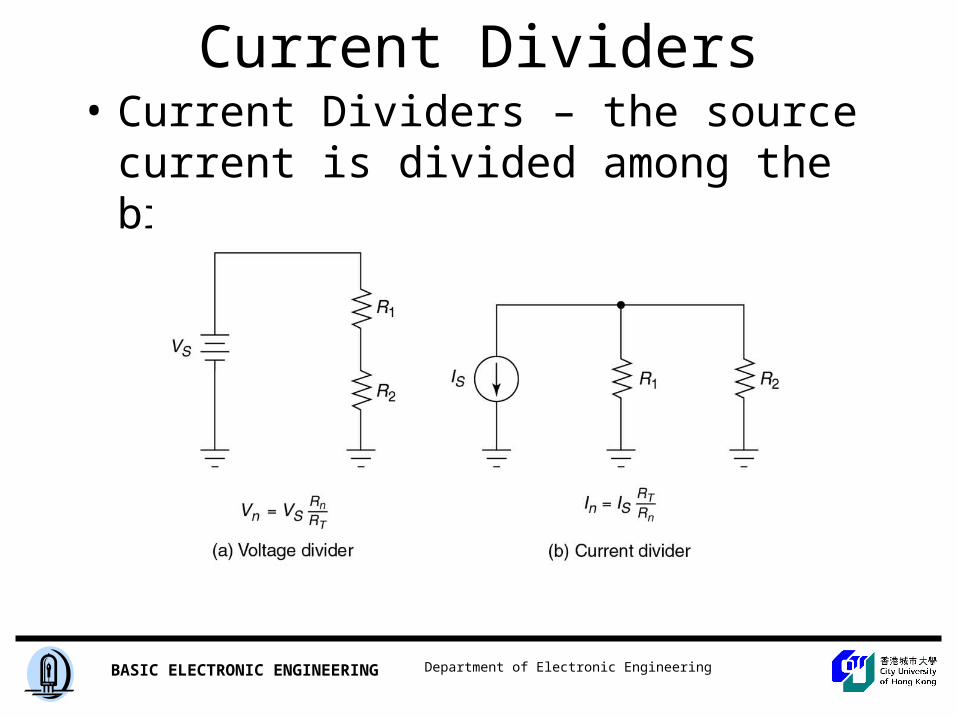
Current Dividers• Current Dividers – the source current is
divided among the branches
Insert Figure 5.15
Department of Electronic EngineeringBASIC ELECTRONIC ENGINEERING
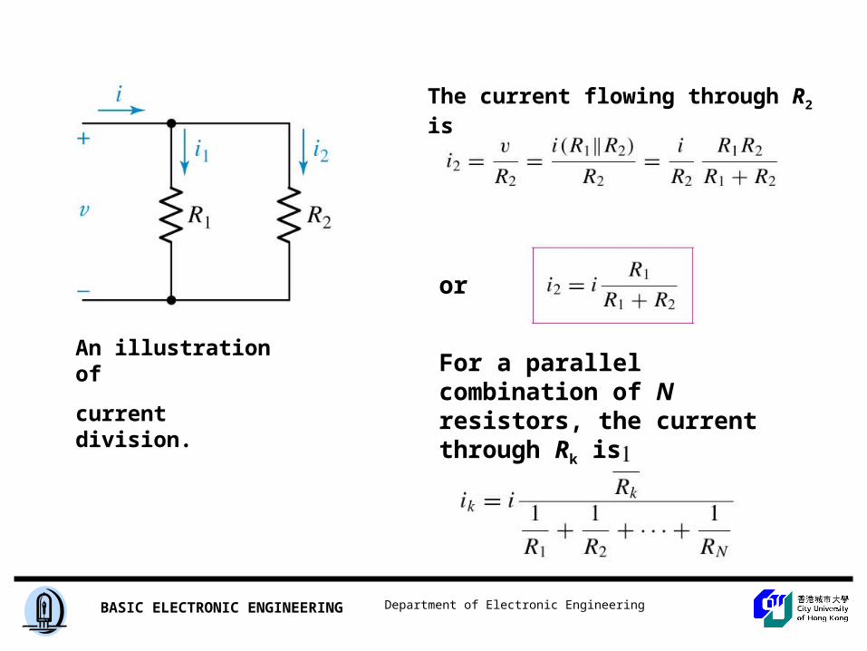
An illustration of
current division.
The current flowing through R2 is
For a parallel combination of N resistors, the current through Rk is
or
Department of Electronic EngineeringBASIC ELECTRONIC ENGINEERING
Practical Current Sources:
• The Effects of Source Resistance– Ideal Current Source – constant current and
infinite internal resistance– Real Current Source – current varies for a
change in load resistance and internal resistance is not infinite
– Internal resistance is usually much greater than the load resistance
Department of Electronic EngineeringBASIC ELECTRONIC ENGINEERING
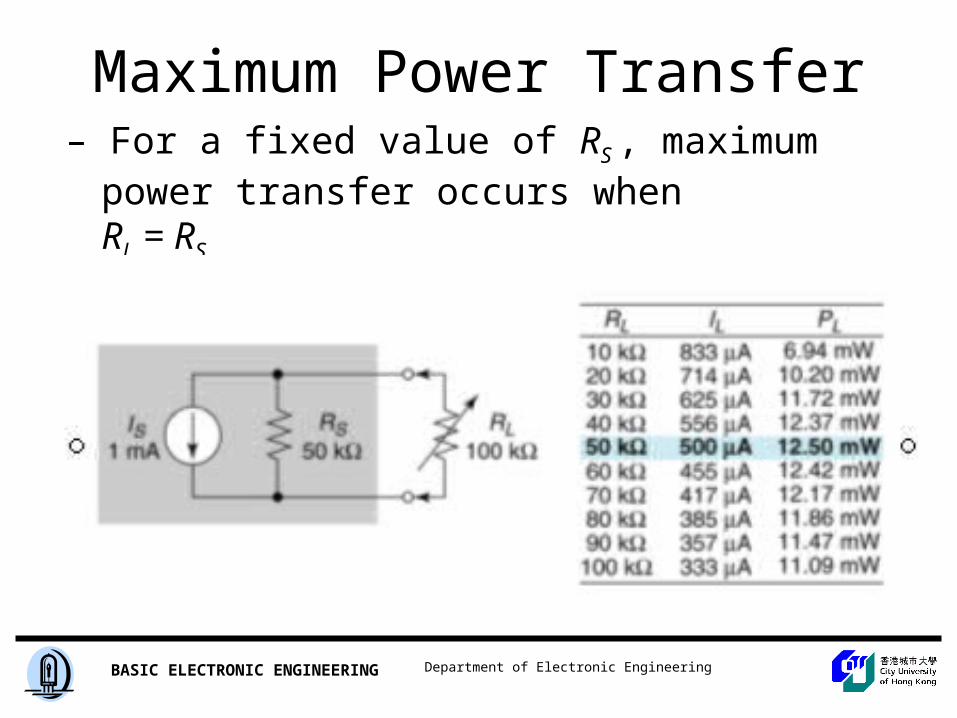
Maximum Power Transfer– For a fixed value of RS , maximum power transfer
occurs when RL = RS
Department of Electronic EngineeringBASIC ELECTRONIC ENGINEERING
Series-Parallel Circuits
Department of Electronic EngineeringBASIC ELECTRONIC ENGINEERING
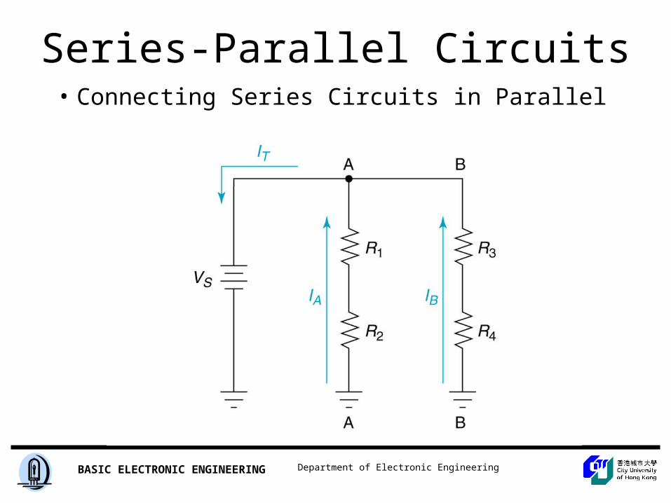
Series-Parallel Circuits• Connecting Series Circuits in Parallel
Insert Figure 6.3
Department of Electronic EngineeringBASIC ELECTRONIC ENGINEERING
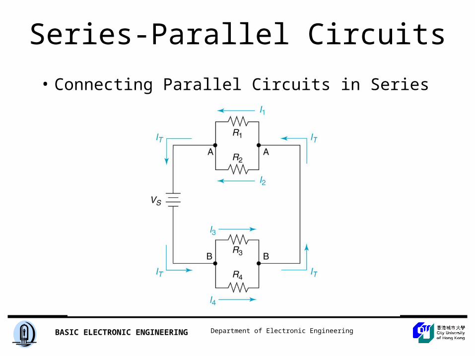
Series-Parallel Circuits
• Connecting Parallel Circuits in Series
Insert Figure 6.5
Department of Electronic EngineeringBASIC ELECTRONIC ENGINEERING
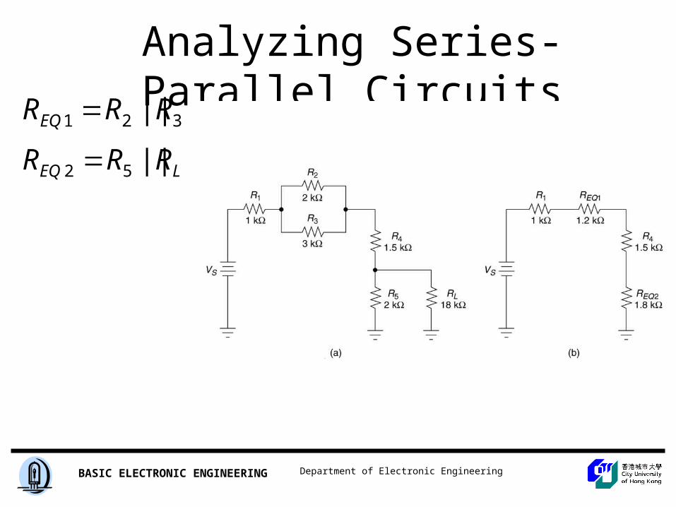
Analyzing Series-Parallel Circuits
LEQ RRR ||52 321 || RRREQ
Department of Electronic EngineeringBASIC ELECTRONIC ENGINEERING
KIRCHHOFF’S VOLTAGE LAW
Formal Expression
Department of Electronic EngineeringBASIC ELECTRONIC ENGINEERING
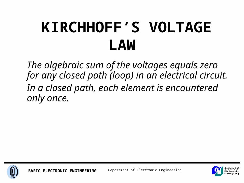
KIRCHHOFF’S VOLTAGE LAW
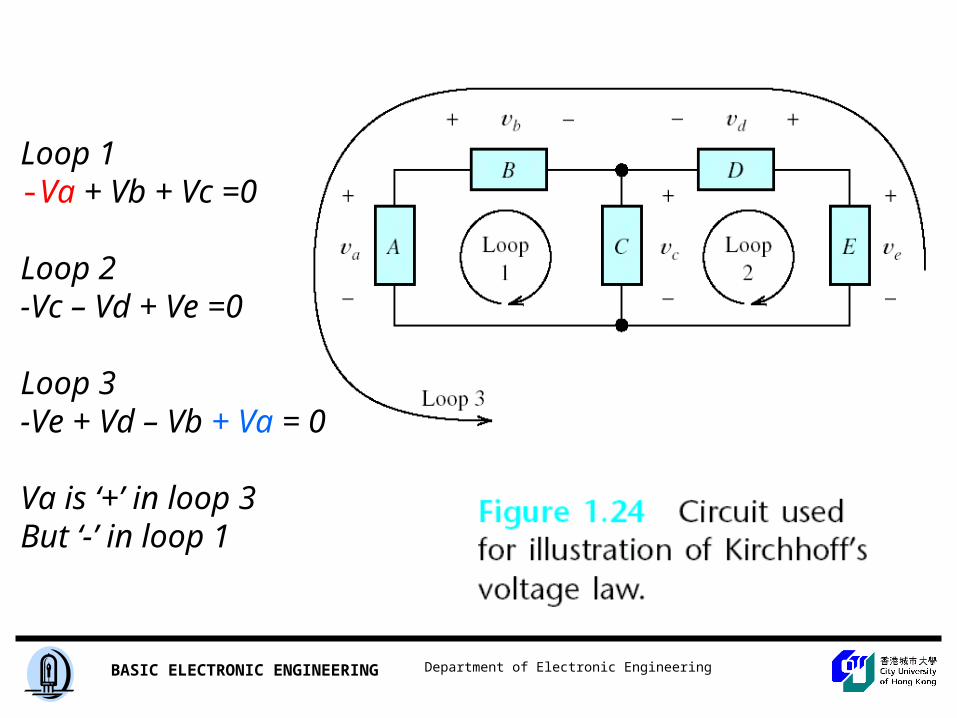
The algebraic sum of the voltages equals zero for any closed path (loop) in an electrical circuit.In a closed path, each element is encountered only once.
Department of Electronic EngineeringBASIC ELECTRONIC ENGINEERING
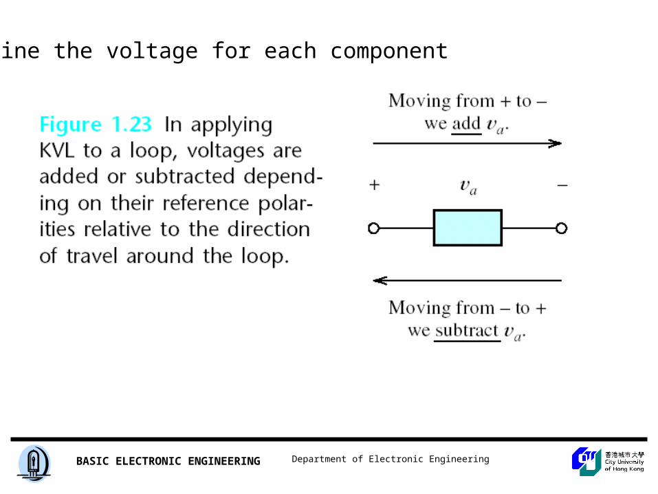
Define the voltage for each component
Department of Electronic EngineeringBASIC ELECTRONIC ENGINEERING
Department of Electronic EngineeringBASIC ELECTRONIC ENGINEERING
Loop 1-Va + Vb + Vc =0
Loop 2 -Vc – Vd + Ve =0
Loop 3-Ve + Vd – Vb + Va = 0
Va is ‘+’ in loop 3But ‘-’ in loop 1
Department of Electronic EngineeringBASIC ELECTRONIC ENGINEERING
VOLTAGE SOURCEAND
CURRENT SOURCE
Department of Electronic EngineeringBASIC ELECTRONIC ENGINEERING
Department of Electronic EngineeringBASIC ELECTRONIC ENGINEERING
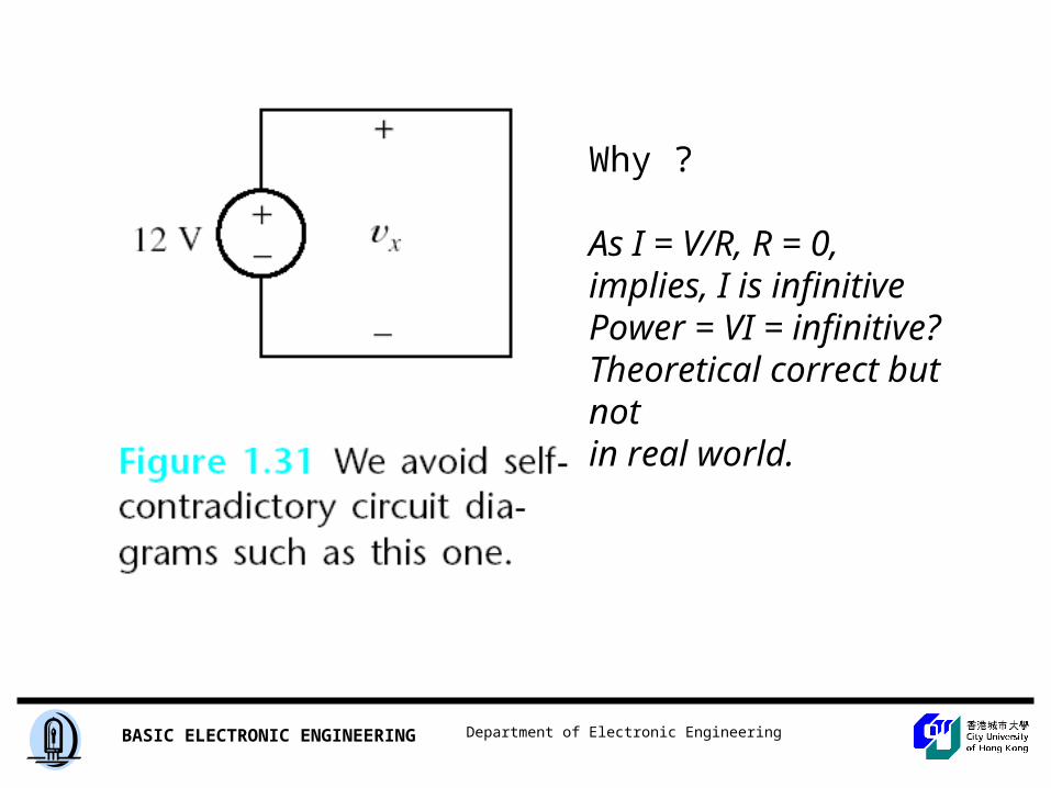
Why ?
As I = V/R, R = 0,implies, I is infinitivePower = VI = infinitive?Theoretical correct but notin real world.
Department of Electronic EngineeringBASIC ELECTRONIC ENGINEERING
Department of Electronic EngineeringBASIC ELECTRONIC ENGINEERING
Department of Electronic EngineeringBASIC ELECTRONIC ENGINEERING
Department of Electronic EngineeringBASIC ELECTRONIC ENGINEERING
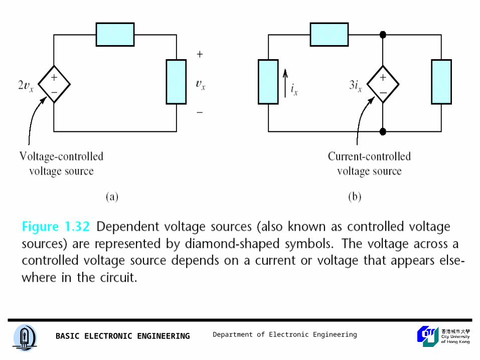
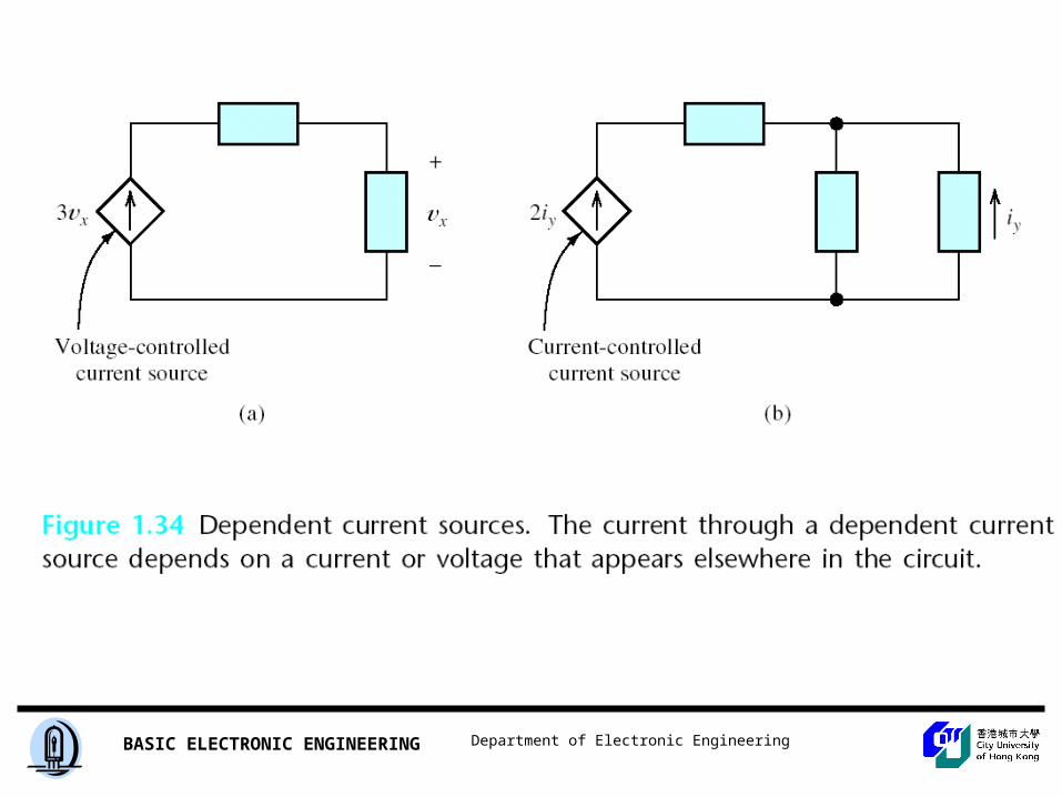
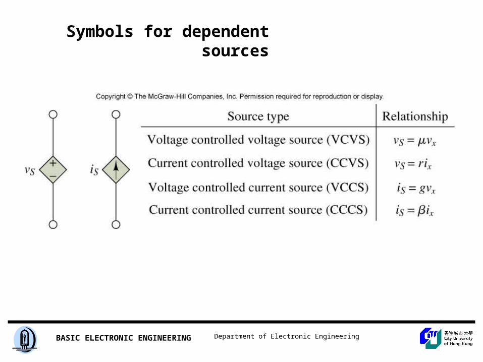
Symbols for dependent sources
Department of Electronic EngineeringBASIC ELECTRONIC ENGINEERING
KIRCHHOFF’S CURRENT LAW
Formal Expression
Department of Electronic EngineeringBASIC ELECTRONIC ENGINEERING
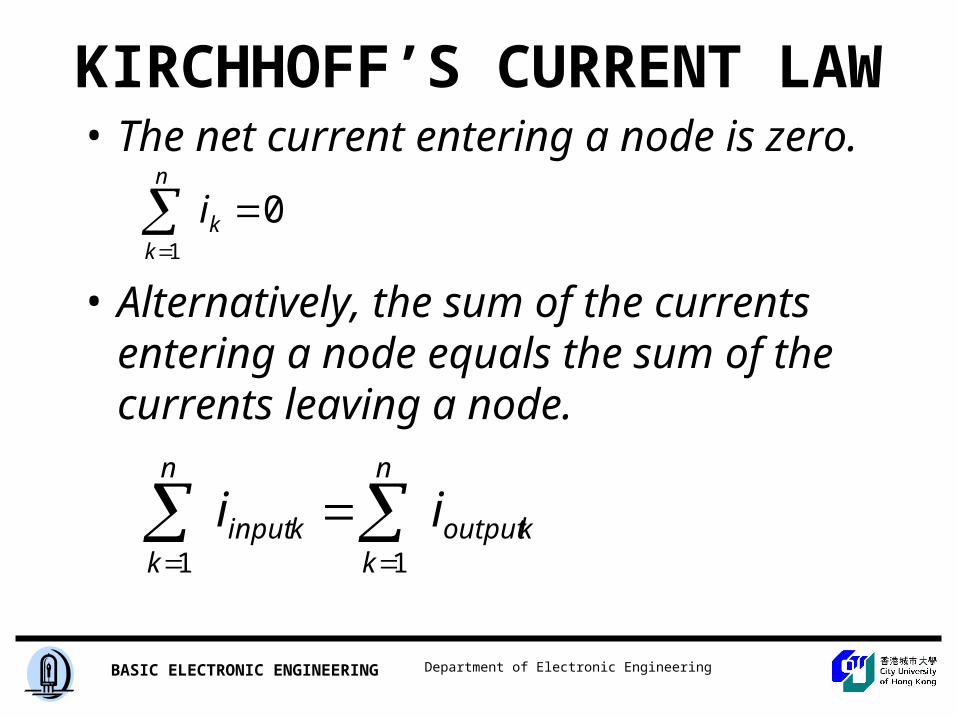
KIRCHHOFF’S CURRENT LAW• The net current entering a node is zero.
• Alternatively, the sum of the currents entering a node equals the sum of the currents leaving a node.
01
k
n
k
i
koutput
n
kkinput
n
k
ii
11
Department of Electronic EngineeringBASIC ELECTRONIC ENGINEERING
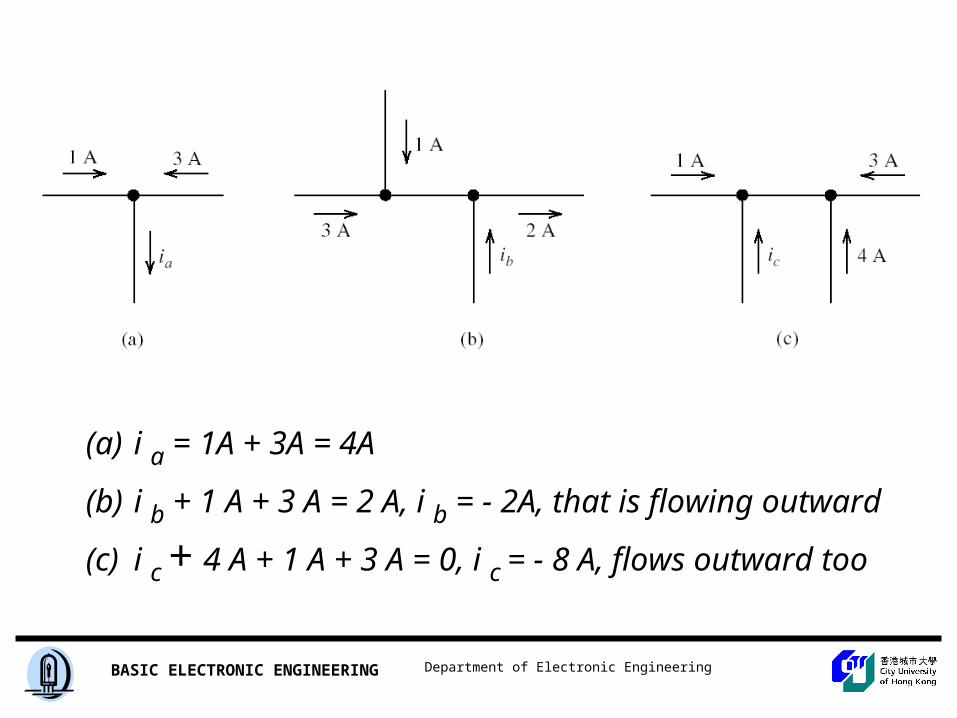
(a) i a = 1A + 3A = 4A
(b) i b + 1 A + 3 A = 2 A, i b = - 2A, that is flowing outward
(c) i c + 4 A + 1 A + 3 A = 0, i c = - 8 A, flows outward too