Embed Size (px)
Citation preview

© February 15, 2017 Dr. Lynn Fuller, Professor
Rochester Institute of Technology
Microelectronic Engineering
Basic Analog Electronic Circuits
Page 1
Basic Analog Electronic Circuits
Dr. Lynn Fuller
Webpage: http://people.rit.edu/lffeeeMicroelectronic Engineering
Rochester Institute of Technology82 Lomb Memorial DriveRochester, NY 14623-5604
Tel (585) 475-2035Email: [email protected]
MicroE webpage: http://www.rit.edu/microelectronic/
2-15-2017 Basic_Analog_Circuits.ppt
ROCHESTER INSTITUTE OF TECHNOLOGYMICROELECTRONIC ENGINEERING

© February 15, 2017 Dr. Lynn Fuller, Professor
Rochester Institute of Technology
Microelectronic Engineering
Basic Analog Electronic Circuits
Page 2
OUTLINE
Introduction
Op Amp
Comparator
Bistable Multivibrator
RC Oscillator
RC Integrator
Peak Detector
Switched Capacitor Amplifier
Capacitors
Design Examples
References
Homework
© February 15, 2017 Dr. Lynn Fuller, Professor
Rochester Institute of Technology
Microelectronic Engineering
Basic Analog Electronic Circuits
Page 3
INTRODUCTION
Analog electronic circuits are different from digital circuits in that the signals are expected to have any value rather than two discrete values. Primitive analog components include the diode, mosfet, BJT, resistor, capacitor, etc,. Analog circuit building blocks include single stage amplifiers, differential amplifiers, constant current sources, voltage references, etc. Basic analog electronic ciruits include the operational amplifier, inverting amplifier, non-inverting amplifier, integrator, bistable multivibrator, peak detector, comparator, RC oscillator, etc. Mixed-mode analog integrated circuits include D-to-A, A-to-D, etc.
This document will introduce some Basic analog electronic circuits.
© February 15, 2017 Dr. Lynn Fuller, Professor
Rochester Institute of Technology
Microelectronic Engineering
Basic Analog Electronic Circuits
Page 4
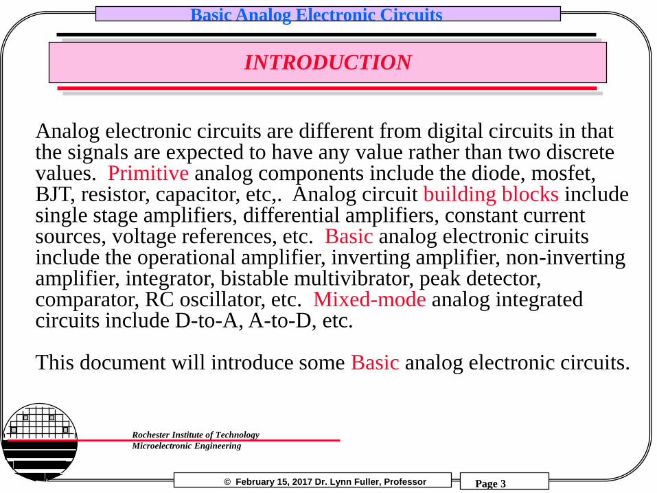
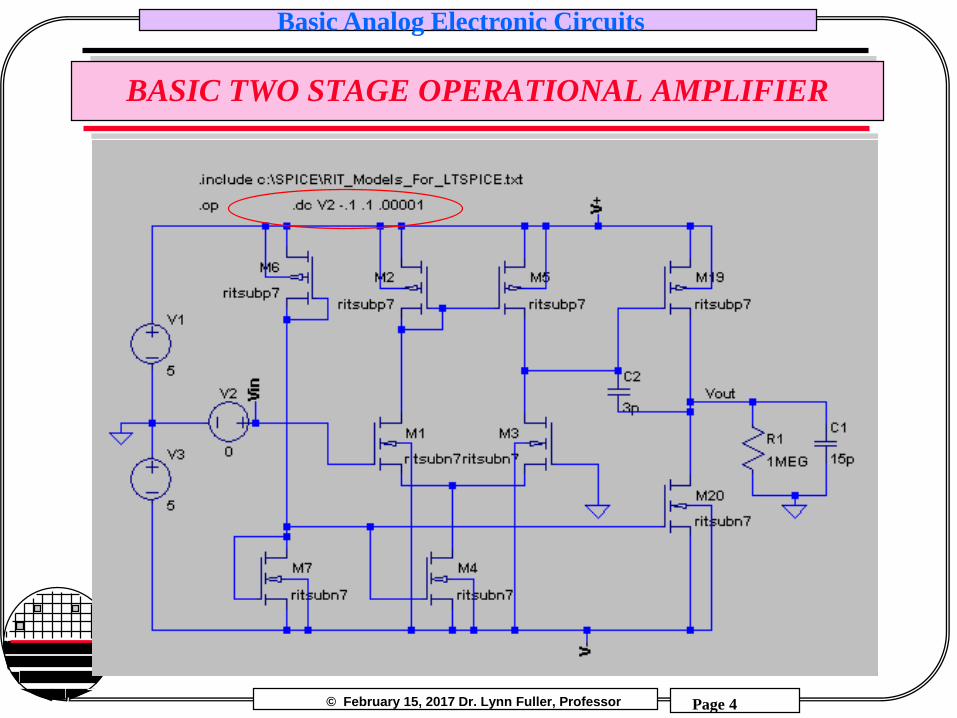
BASIC TWO STAGE OPERATIONAL AMPLIFIER

© February 15, 2017 Dr. Lynn Fuller, Professor
Rochester Institute of Technology
Microelectronic Engineering
Basic Analog Electronic Circuits
Page 5
BASIC TWO STAGE OPERATIONAL AMPLIFIER

© February 15, 2017 Dr. Lynn Fuller, Professor
Rochester Institute of Technology
Microelectronic Engineering
Basic Analog Electronic Circuits
Page 6
BASIC TWO STAGE OPERATIONAL AMPLIFIER
Gain = 1.5K V/V
© February 15, 2017 Dr. Lynn Fuller, Professor
Rochester Institute of Technology
Microelectronic Engineering
Basic Analog Electronic Circuits
Page 7
BASIC TWO STAGE OPERATIONAL AMPLIFIER

© February 15, 2017 Dr. Lynn Fuller, Professor
Rochester Institute of Technology
Microelectronic Engineering
Basic Analog Electronic Circuits
Page 8
BASIC TWO STAGE OPERATIONAL AMPLIFIER
Small Signal gain ~ 60 dB
Frequency Response

© February 15, 2017 Dr. Lynn Fuller, Professor
Rochester Institute of Technology
Microelectronic Engineering
Basic Analog Electronic Circuits
Page 9
OPERATIONAL AMPLIFIER LAYOUT
100um

© February 15, 2017 Dr. Lynn Fuller, Professor
Rochester Institute of Technology
Microelectronic Engineering
Basic Analog Electronic Circuits
Page 10
BASIC TWO STAGE OPERATIONAL AMPLIFIER
Change RL to 1000 ohm
© February 15, 2017 Dr. Lynn Fuller, Professor
Rochester Institute of Technology
Microelectronic Engineering
Basic Analog Electronic Circuits
Page 11
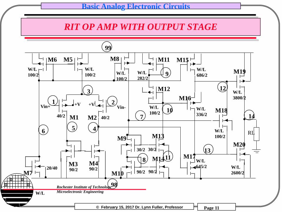
RIT OP AMP WITH OUTPUT STAGE
20/40
M7
M140/2
1
M6
W/L
100/2
6
M2
Vin+
99
40/2
Vin-
M5
W/L
100/2
3
+V +V
98
2
M490/2
M390/2
45
M14
90/2M10 90/2
13
M13
30/230/2
M17
M20
M18
M8 M15
W/L
686/2
10
M19
W/L
3800/2
14
M11
12
M9
W/L
M16
W/L
336/27
RL
M12
9
118
W/L
282/2W/L
100/2
W/L
2600/2
W/L
100/2
W/L
645/2
W/L
100/2

© February 15, 2017 Dr. Lynn Fuller, Professor
Rochester Institute of Technology
Microelectronic Engineering
Basic Analog Electronic Circuits
Page 12
RIT OP AMP WITH OUTPUT STAGE

© February 15, 2017 Dr. Lynn Fuller, Professor
Rochester Institute of Technology
Microelectronic Engineering
Basic Analog Electronic Circuits
Page 13
RIT OP AMP WITH OUTPUT STAGE

© February 15, 2017 Dr. Lynn Fuller, Professor
Rochester Institute of Technology
Microelectronic Engineering
Basic Analog Electronic Circuits
Page 14
OPERATIONAL AMPLIFERS
The 741 Op Amp is a general purpose bipolar integrated circuit that has input bias current of 80nA, and input voltage of +/- 15 volts @ supply maximum of +/- 18 volts. The output voltage can not go all the way to the + and - supply voltage. At a minimum supply of +/- 5 volts the output voltage can go ~6 volts p-p.
The newer Op Amps have rail-rail output swing and supply voltages as low as +/- 1.5 volts. The MOSFET input bias currents are ~ 1pA. The NJU7031 is an example of this type of Op Amp.

© February 15, 2017 Dr. Lynn Fuller, Professor
Rochester Institute of Technology
Microelectronic Engineering
Basic Analog Electronic Circuits
Page 15
LOW VOLTAGE, RAIL-TO-RAIL OP AMP

© February 15, 2017 Dr. Lynn Fuller, Professor
Rochester Institute of Technology
Microelectronic Engineering
Basic Analog Electronic Circuits
Page 16
SOME BASIC ANALOG ELECTRONIC CIRCUITS
These circuits should be familiar:
-
+VoVin
R2R1
Inverting Amplifier
-
+Vo
Vin
R2R1
Non-Inverting Amplifier
-
+
Unity Gain Buffer
-
+VoVin
C
R
Integrator
VinVo
Vo= - Vin R2/R1
Vo= Vin
Vo= Vin (1 + R2/R1)
Vo= -1/RC Vin dt

© February 15, 2017 Dr. Lynn Fuller, Professor
Rochester Institute of Technology
Microelectronic Engineering
Basic Analog Electronic Circuits
Page 17
SOME BASIC ANALOG ELECTRONIC CIRCUITS
-
+VoV2
R3
R1
Inverting Summer
V1
R1
Vo= ( -R3/R1) (V1 + V2)
Difference Amplifier
Vo= Rf/Rin (V1-V2)
Vo-+
Rin
Rf
V1
V2
RfRin

© February 15, 2017 Dr. Lynn Fuller, Professor
Rochester Institute of Technology
Microelectronic Engineering
Basic Analog Electronic Circuits
Page 18
COMPARATOR
-
+Vo
Vin
Vo
Vin
Vref
+V
-VVref
+V
-V
+V-V
Measured
Theoretical

© February 15, 2017 Dr. Lynn Fuller, Professor
Rochester Institute of Technology
Microelectronic Engineering
Basic Analog Electronic Circuits
Page 19
BISTABLE CIRCUIT WITH HYSTERESIS
-
+Vo
Vin
+V
-V
R2R1 Vo
Vin
VTH
+V
-V
VTL
Sedra and Smith pg 1187Measured
Theoretical

© February 15, 2017 Dr. Lynn Fuller, Professor
Rochester Institute of Technology
Microelectronic Engineering
Basic Analog Electronic Circuits
Page 20
RC INTEGRATOR
C
VoutR
Vin
Vin
t
+Va
-Va
Vout
t
+Va
-Va
Smaller RC
t1
Vout = (-Va) + [2Va(1-e-t/RC)] for 0<t<t1
If R=1MEG and C=10pF find RC=10us
so t1 might be ~20us

© February 15, 2017 Dr. Lynn Fuller, Professor
Rochester Institute of Technology
Microelectronic Engineering
Basic Analog Electronic Circuits
Page 21
OSCILLATOR (MULTIVIBRATOR)
-
+Vo
C
+V
-V
R2R1
R
Vo
tt1
VT
+V
-V
Bistable Circuit with Hysteresis and RC Integrator
Period = T = 2RC ln1+Vt/V
1-Vt/V

© February 15, 2017 Dr. Lynn Fuller, Professor
Rochester Institute of Technology
Microelectronic Engineering
Basic Analog Electronic Circuits
Page 22
PEAK DETECTOR
-
+Vo
C
Variable Vin
Diode reverse leakage current ~100nA

© February 15, 2017 Dr. Lynn Fuller, Professor
Rochester Institute of Technology
Microelectronic Engineering
Basic Analog Electronic Circuits
Page 23
CAPACITORS
Capacitor - a two terminal device whose current is proportional to the time rate of change of the applied voltage;
I = C dV/dt
a capacitor C is constructed of any two conductors separated by an insulator. The capacitance of such a structure is:
C = eo er Area/d where eo is the permitivitty of free spaceer is the relative permitivittyArea is the overlap area of the two conductor separated by distance deo = 8.85E-14 F/cm
I
C V
+
-
Area
der air = 1er SiO2 = 3.9

© February 15, 2017 Dr. Lynn Fuller, Professor
Rochester Institute of Technology
Microelectronic Engineering
Basic Analog Electronic Circuits
Page 24
DIELECTRIC CONSTANT OF SELECTED MATERIALS
Vacuum 1
Air 1.00059
Acetone 20
Barium strontium titanate
500
Benzene 2.284
Conjugated Polymers
6 to 100,000
Ethanol 24.3
Glycerin 42.5
Glass 5-10
Methanol 30
Photoresist 3
Plexiglass 3.4
Polyimide 2.8
Rubber 3
Silicon 11.7
Silicon dioxide 3.9
Silicon Nitride 7.5
Teflon 2.1
Water 80-88
http://www.asiinstruments.com/technical/Dielectric%20Constants.htm

© February 15, 2017 Dr. Lynn Fuller, Professor
Rochester Institute of Technology
Microelectronic Engineering
Basic Analog Electronic Circuits
Page 25
CALCULATIONS

© February 15, 2017 Dr. Lynn Fuller, Professor
Rochester Institute of Technology
Microelectronic Engineering
Basic Analog Electronic Circuits
Page 26
DESIGN EXAMPLE
Square Wave Generator
RC Integrator & Capacitor Sensor
Peak Detector
Comparator
© February 15, 2017 Dr. Lynn Fuller, Professor
Rochester Institute of Technology
Microelectronic Engineering
Basic Analog Electronic Circuits
Page 27
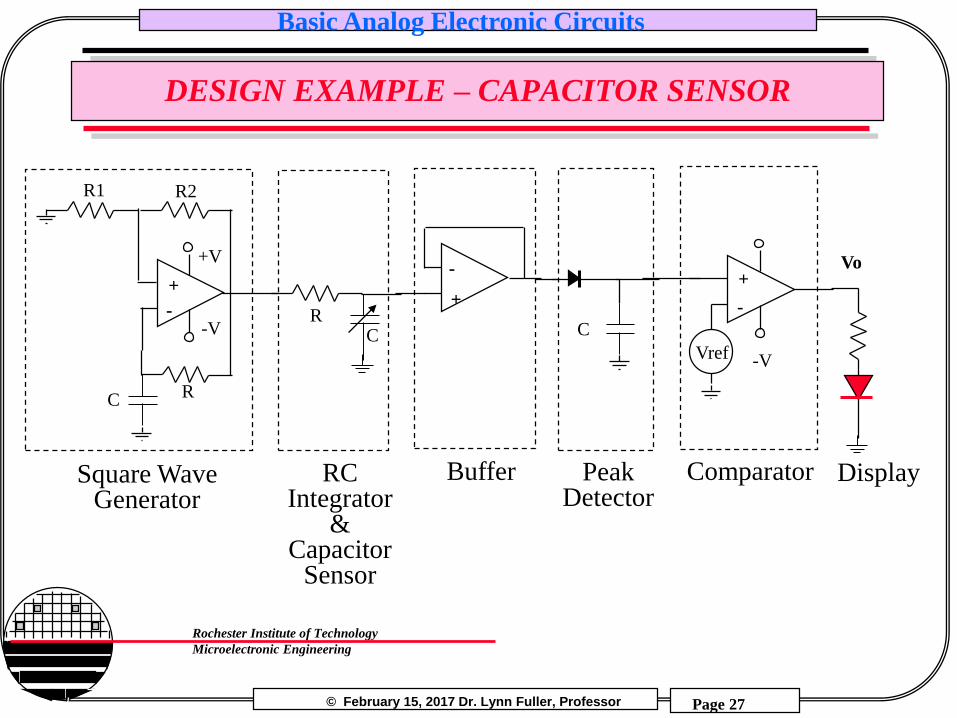
DESIGN EXAMPLE – CAPACITOR SENSOR
-
+
C
+V
-V
R2R1
R
C
+
-
Vo
Vref -V
CR
-
+
Square WaveGenerator
ComparatorPeak Detector
RC Integrator
&Capacitor
Sensor
Buffer Display

© February 15, 2017 Dr. Lynn Fuller, Professor
Rochester Institute of Technology
Microelectronic Engineering
Basic Analog Electronic Circuits
Page 28
EXAMPLE LABORATORY RESULTS
Square WaveGenerator
Output
BufferOutput
Display
Smaller Capacitance
Larger Capacitance

© February 15, 2017 Dr. Lynn Fuller, Professor
Rochester Institute of Technology
Microelectronic Engineering
Basic Analog Electronic Circuits
Page 29
CAPACITOR MICROPHONE PLUS AMPLIFIER
+
3.3V
-3.3
NJU703
i
V
R
CVo
i
Vo = - i R
i = d (CV)/dt , V is constant C = Co + Cm sin (2pft)
i = V Cm 2 p f cos (2pft)
© February 15, 2017 Dr. Lynn Fuller, Professor
Rochester Institute of Technology
Microelectronic Engineering
Basic Analog Electronic Circuits
Page 30
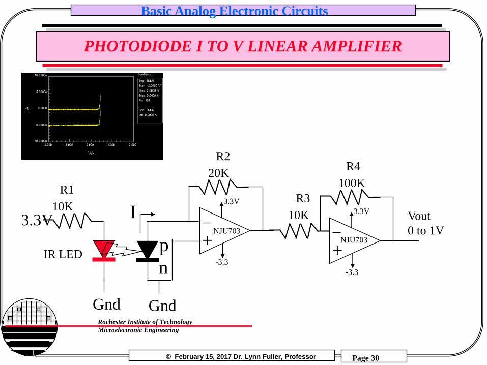
PHOTODIODE I TO V LINEAR AMPLIFIER
+p
n
Vout
0 to 1V
R2
I
Gnd
20K
3.3V
-3.3
3.3V
Gnd
IR LED +
R4
100K
3.3V
-3.3
R3
10K
R1
10K
NJU703NJU703

© February 15, 2017 Dr. Lynn Fuller, Professor
Rochester Institute of Technology
Microelectronic Engineering
Basic Analog Electronic Circuits
Page 31
PHOTO DIODE I TO V LOG AMPLIFIER
+
p
nVout
0 to 1V
I
Gnd
3.3V
-3.3
NJU7033.3V
Gnd
IR LED
R1
20K
1N4448
Vout vs. Diode Current
0.0
0.5
1.0
1.5
2.0
2.5
3.0
3.5
0.01 0.1 1 10 100 1000 10000
Diode Current (uA)
Ou
tpu
t V
olt
ag
e (
V)
Linear Amplifier
Log Amplifier
Linear amplifier uses 100K ohm in place of the 1N4448
Photodiode

© February 15, 2017 Dr. Lynn Fuller, Professor
Rochester Institute of Technology
Microelectronic Engineering
Basic Analog Electronic Circuits
Page 32
PHOTO DIODE I TO V INTEGRATING AMPLIFIER
Rf
-+
Ri-+
C
Reset
Internal
100 pF
Analog Vout
Integrator and amplifier allow for measurement at low light levels

© February 15, 2017 Dr. Lynn Fuller, Professor
Rochester Institute of Technology
Microelectronic Engineering
Basic Analog Electronic Circuits
Page 33
DIODE AS A TEMPERATURE SENSOR
Compare with theoretical -2.2mV/°C
Poly Heater, Buried pn Diode,N+ Poly to Aluminum Thermocouple
P+
N+

© February 15, 2017 Dr. Lynn Fuller, Professor
Rochester Institute of Technology
Microelectronic Engineering
Basic Analog Electronic Circuits
Page 34
SIGNAL CONDITIONING FOR TEMPERATURE SENSOR
p
n
Gnd
I3.3V
R1
20K
0.2 < Vout < 0.7V
+
-

© February 15, 2017 Dr. Lynn Fuller, Professor
Rochester Institute of Technology
Microelectronic Engineering
Basic Analog Electronic Circuits
Page 35
OP AMP CONSTANT CURRENT SOURCE
Vo -+Vs
Vo+
RxR1L
oad
R
I =
Vs/
R
Floating Load Grounded Load
Vs
Load
Rx/R1=R3/R2
I = Vs/R2
R3R2

© February 15, 2017 Dr. Lynn Fuller, Professor
Rochester Institute of Technology
Microelectronic Engineering
Basic Analog Electronic Circuits
Page 36
RESISTIVE PRESSURE SENSOR
R1R3
R2R4
Gnd
+5 Volts Vo2
Vo1
Resistors on a DiaphragmGnd
5 Volts
R1=427 R3=427
R2=427R4=427
Vo2=2.5vVo1=2.5v
No Pressure
Vo2-Vo1 = 0

© February 15, 2017 Dr. Lynn Fuller, Professor
Rochester Institute of Technology
Microelectronic Engineering
Basic Analog Electronic Circuits
Page 37
INSTRUMENTATION AMPLIFIER
Gnd
5 Volts
R1=427.6 R3=426.4
R2=426.4 R4=427.6
Vo2=2.5035vVo1=2.4965v
With PressureVo2-Vo1 = 0.007v
=7 mV
Vo-
+
R3
R4
Vo2-+
Vo1
-
+
R4
Gnd
R3
V1
V2
R2
R1
R2
Vo = (V2-V1) 2 R4
R3
R2
R11 +

© February 15, 2017 Dr. Lynn Fuller, Professor
Rochester Institute of Technology
Microelectronic Engineering
Basic Analog Electronic Circuits
Page 38
POWER OUTPUT STAGE
-
+
VoVin
Rload
+V
-V
-V
+V

© February 15, 2017 Dr. Lynn Fuller, Professor
Rochester Institute of Technology
Microelectronic Engineering
Basic Analog Electronic Circuits
Page 39
REFERENCES
1. Switched Capacitor Circuits, Phillip E. Allen and Edgar Sanchez-Sinencio, Van Nostrand Reinhold Publishers, 1984.
2. “Active Filter Design Using Operational Transconductance Amplifiers: A Tutorial,” Randall L. Geiger and Edgar Sanchez-Sinencio, IEEE Circuits and Devices Magazine, March 1985, pg. 20-32.
3. Microelectronic Circuits, 5th Edition, Sedra and Smith

© February 15, 2017 Dr. Lynn Fuller, Professor
Rochester Institute of Technology
Microelectronic Engineering
Basic Analog Electronic Circuits
Page 40
HOMEWORK – BASIC ANALOG CIRCUITS
1. Create one good homework problem and the solution related to
the material covered in this document. (for next years students)
2. Design a bistable multivibrator with Vth of +/- 7.5 volts and
frequency of 5 Khz.
3. Design a temperature sensor circuit that will shut down a heater
if the temperature exceeds 90°C
4. Design a peak detector that will respond to changes in input in
less than one second.
5. Derive the equation for the oscillator on page 15
(multivibrator).
6. Derive the voltage gain equation for the difference amplifier.

© February 15, 2017 Dr. Lynn Fuller, Professor
Rochester Institute of Technology
Microelectronic Engineering
Basic Analog Electronic Circuits
Page 41
DERIVE GAIN EQUATION FOR DIFFERENCE AMP
Difference Amplifier
Vo= Rf/Rin (V1-V2)
Vo-+
Rin
Rf
V1
V2
RfRin
Vx
Vx = V1Rf
Rf + Rin
I
I
I = (V2-Vx)/Rin
Vo = -I Rf + Vx