Embed Size (px)
DESCRIPTION
Owners manual for Delta dust collector
Citation preview

INS
TRU
CTIO
NM
AN
UA
L1½ H.P. Single-Stage
Dust Collector(Model 50-850)
PART NO. 902115 - 11-15-02Copyright © 2002 Delta Machinery
ESPAÑOL: PÁGINA 15To learn more about DELTA MACHINERY visit our website at: www.deltamachinery.com.For Parts, Service, Warranty or other Assistance,
please call 1-800-223-7278 (In Canada call 1-800-463-3582).
2
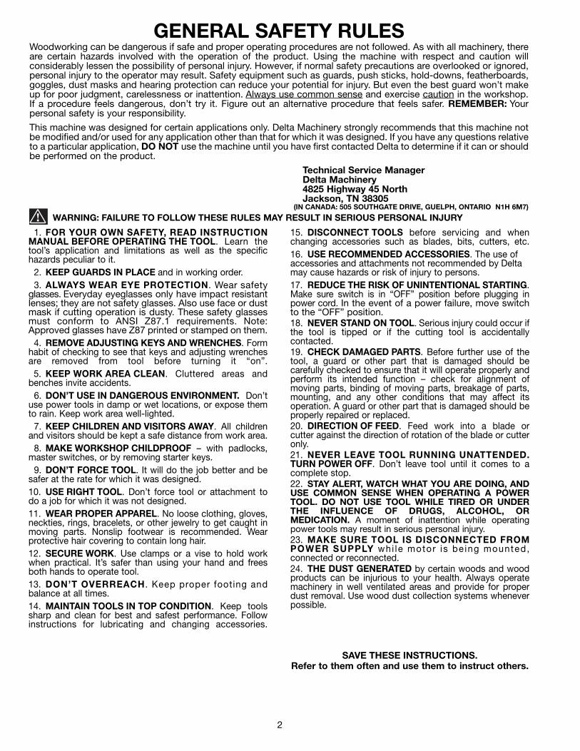
GENERAL SAFETY RULESWoodworking can be dangerous if safe and proper operating procedures are not followed. As with all machinery, thereare certain hazards involved with the operation of the product. Using the machine with respect and caution willconsiderably lessen the possibility of personal injury. However, if normal safety precautions are overlooked or ignored,personal injury to the operator may result. Safety equipment such as guards, push sticks, hold-downs, featherboards,goggles, dust masks and hearing protection can reduce your potential for injury. But even the best guard won’t makeup for poor judgment, carelessness or inattention. Always use common sense and exercise caution in the workshop.If a procedure feels dangerous, don’t try it. Figure out an alternative procedure that feels safer. REMEMBER: Yourpersonal safety is your responsibility.
This machine was designed for certain applications only. Delta Machinery strongly recommends that this machine notbe modified and/or used for any application other than that for which it was designed. If you have any questions relativeto a particular application, DO NOT use the machine until you have first contacted Delta to determine if it can or shouldbe performed on the product.
Technical Service ManagerDelta Machinery4825 Highway 45 NorthJackson, TN 38305
(IN CANADA: 505 SOUTHGATE DRIVE, GUELPH, ONTARIO N1H 6M7)
WARNING: FAILURE TO FOLLOW THESE RULES MAY RESULT IN SERIOUS PERSONAL INJURY
1. FOR YOUR OWN SAFETY, READ INSTRUCTIONMANUAL BEFORE OPERATING THE TOOL. Learn thetool’s application and limitations as well as the specifichazards peculiar to it.
2. KEEP GUARDS IN PLACE and in working order.3. ALWAYS WEAR EYE PROTECTION. Wear safety
glasses. Everyday eyeglasses only have impact resistantlenses; they are not safety glasses. Also use face or dustmask if cutting operation is dusty. These safety glassesmust conform to ANSI Z87.1 requirements. Note:Approved glasses have Z87 printed or stamped on them.
4. REMOVE ADJUSTING KEYS AND WRENCHES. Formhabit of checking to see that keys and adjusting wrenchesare removed from tool before turning it “on”.
5. KEEP WORK AREA CLEAN. Cluttered areas andbenches invite accidents.
6. DON’T USE IN DANGEROUS ENVIRONMENT. Don’tuse power tools in damp or wet locations, or expose themto rain. Keep work area well-lighted.
7. KEEP CHILDREN AND VISITORS AWAY. All childrenand visitors should be kept a safe distance from work area.
8. MAKE WORKSHOP CHILDPROOF – with padlocks,master switches, or by removing starter keys.
9. DON’T FORCE TOOL. It will do the job better and besafer at the rate for which it was designed.10. USE RIGHT TOOL. Don’t force tool or attachment todo a job for which it was not designed.11. WEAR PROPER APPAREL. No loose clothing, gloves,neckties, rings, bracelets, or other jewelry to get caught inmoving parts. Nonslip footwear is recommended. Wearprotective hair covering to contain long hair.12. SECURE WORK. Use clamps or a vise to hold workwhen practical. It’s safer than using your hand and freesboth hands to operate tool.13. DON’T OVERREACH . Keep proper footing andbalance at all times.14. MAINTAIN TOOLS IN TOP CONDITION. Keep toolssharp and clean for best and safest performance. Followinstructions for lubricating and changing accessories.
15. DISCONNECT TOOLS before servicing and whenchanging accessories such as blades, bits, cutters, etc.16. USE RECOMMENDED ACCESSORIES. The use ofaccessories and attachments not recommended by Deltamay cause hazards or risk of injury to persons.17. REDUCE THE RISK OF UNINTENTIONAL STARTING.Make sure switch is in “OFF” position before plugging inpower cord. In the event of a power failure, move switchto the “OFF” position.18. NEVER STAND ON TOOL. Serious injury could occur ifthe tool is tipped or if the cutting tool is accidentallycontacted.19. CHECK DAMAGED PARTS. Before further use of thetool, a guard or other part that is damaged should becarefully checked to ensure that it will operate properly andperform its intended function – check for alignment ofmoving parts, binding of moving parts, breakage of parts,mounting, and any other conditions that may affect itsoperation. A guard or other part that is damaged should beproperly repaired or replaced.20. DIRECTION OF FEED. Feed work into a blade orcutter against the direction of rotation of the blade or cutteronly.21. NEVER LEAVE TOOL RUNNING UNATTENDED.TURN POWER OFF. Don’t leave tool until it comes to acomplete stop.22. STAY ALERT, WATCH WHAT YOU ARE DOING, ANDUSE COMMON SENSE WHEN OPERATING A POWERTOOL. DO NOT USE TOOL WHILE TIRED OR UNDERTHE INFLUENCE OF DRUGS, ALCOHOL, ORMEDICATION. A moment of inattention while operatingpower tools may result in serious personal injury.23. MAKE SURE TOOL IS DISCONNECTED FROMPOWER SUPPLY whi le motor is be ing mounted,connected or reconnected.24. THE DUST GENERATED by certain woods and woodproducts can be injurious to your health. Always operatemachinery in well ventilated areas and provide for properdust removal. Use wood dust collection systems wheneverpossible.
SAVE THESE INSTRUCTIONS. Refer to them often and use them to instruct others.
3
ADDITIONAL SAFETY RULES FORDUST COLLECTORS
WARNING: FAILURE TO FOLLOW THESE RULES MAY RESULT IN SERIOUS PERSONAL INJURY.
1. DO NOT OPERATE THIS MACHINE until it isassembled and installed according to the instructions.
2. OBTAIN ADVICE FROM YOUR SUPERVISOR,instructor, or another qualified person if you are notfamiliar with the operation of this machine.
3. FOLLOW ALL WIRING CODES and recommendedelectrical connections.
4. DO NOT leave the dust collector plugged into theelectrical outlet. Unplug dust collector from the outletwhen not in use and before servicing, changing bags,unclogging and cleaning.
5. ALWAYS turn all controls “OFF” before unpluggingthe dust collector.
6. TO REDUCE THE RISK OF ELECTRICAL SHOCK,do not use on wet surfaces. Do not expose to rain. Storeindoors.
7. DO NOT use the dust collector to pick upflammable or combustible liquids, such as gasoline.NEVER use the dust collector near any flammable orcombustible liquids.
8. USE the dust collector to pick up wood materialsonly. DO NOT use the dust collector to pick up metalshavings, metal dust, or metal parts.
9. NEVER use the dust collector to dissipate fumesor smoke. NEVER pick up anything that is burning orsmoking, such as cigarettes, matches or hot ashes.
10. DO NOT pull the dust collector by the power cord.NEVER allow the power cord to come in contact withsharp edges, hot surfaces, oil or grease. Do not placeanything over the top of the power cord.
11. DO NOT unplug the dust collector by pulling on thepower cord. ALWAYS grasp the plug, not the cord.
12. DO NOT handle the plug or dust collector with wethands.
13. REPLACE a damaged cord immediately. DO NOTuse a damaged cord or plug. If the dust collector is notoperating properly, or has been damaged, left outdoorsor has been in contact with water, take it to anAuthorized Service Center for service.
14. DO NOT use the dust collector as a toy. DO NOTuse near or around children.
15. DO NOT insert fingers or foreign objects into thedust intake port or discharge port. Keep hair, looseclothing, fingers, and all body parts away from openingsand moving parts of the dust collector.
16. DO NOT use with any opening blocked; keepopenings free of dust, lint, hair, and anything that mayreduce air flow.
17. NEVER use the dust collector without the dustcollection bag in place and properly secured.
18. ALWAYS use intake cover to cover dust port whenthe dust collector is not in use or mounted to asupporting surface for storage.
19. PERIODICALLY INSPECT dust bag for any cuts,rips or tears. NEVER operate the dust collector with adamaged bag or vacuum hose.
20. USE EXTRA CARE when cleaning on stairs.
21. TURN THE MACHINE “OFF” AND DISCONNECTTHE MACHINE from the power source before installingor removing accessories, before adjusting or changingset-ups, or when making repairs.
22. TURN THE MACHINE “OFF”, disconnect themachine from the power source, and clean thetable/work area before leaving the machine. LOCK THESWITCH IN THE “OFF” POSITION to preventunauthorized use.
23. ADDITIONAL INFORMATION regarding the safeand proper operation of this tool is available from thePower Tool Institute, 1300 Summer Avenue, Cleveland,OH 44115-2851. Information is also available from theNational Safety Council, 1121 Spring Lake Drive, Itasca,IL 60143-3201. Please refer to the American NationalStandards Institute ANSI 01.1 Safety Requirements forWoodworking Machines and the U.S. Department ofLabor OSHA 1910.213 Regulations.
SAVE THESE INSTRUCTIONS. Refer to them often
and use them to instruct others.
4
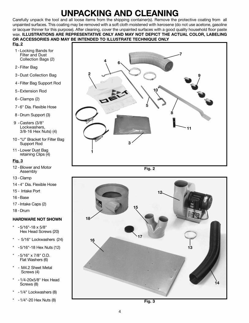
UNPACKING AND CLEANINGCarefully unpack the tool and all loose items from the shipping container(s). Remove the protective coating from allunpainted surfaces. This coating may be removed with a soft cloth moistened with kerosene (do not use acetone, gasolineor lacquer thinner for this purpose). After cleaning, cover the unpainted surfaces with a good quality household floor pastewax. ILLUSTRATIONS ARE REPRESENTATIVE ONLY AND MAY NOT DEPICT THE ACTUAL COLOR, LABELINGOR ACCESSORIES AND MAY BE INTENDED TO ILLUSTRATE TECHNIQUE ONLYFig. 2
1 -Locking Bands forFilter and DustCollection Bags (2)
2 -Filter Bag
3-Dust Collection Bag
4-Filter Bag Support Rod
5-Extension Rod
6-Clamps (2)
7 -6" Dia. Flexible Hose
8 -Drum Support (3)
9 -Casters (3/8" Lockwashers, 3/8-16 Hex Nuts) (4)
10 -“U” Bracket for Filter BagSupport Rod
11 -Lower Dust Bag retaining Clips (4)
Fig. 3
12 -Blower and MotorAssembly
13 -Clamp
14 -4" Dia. Flexible Hose
15 - Intake Port
16 -Base
17 - Intake Caps (2)
18 -Drum
Fig. 2
Fig. 3
1
2
3
4
5
6
7
8
9
10
12
13
14
15
1617
18
11
HARDWARE NOT SHOWN
* -5/16"-18 x 5/8"Hex Head Screws (20)
* - 5/16" Lockwashers (24)
* -5/16"-18 Hex Nuts (12)
* -5/16" x 7/8" O.D. Flat Washers (6)
* - M4.2 Sheet MetalScrews (4)
* -1/4-20x5/8" Hex Head Screws (8)
* -1/4" Lockwashers (8)
* -1/4"-20 Hex Nuts (8)

5
ASSEMBLY
Fig. 4
Fig. 5
Fig. 6
Fig. 8Fig. 7
ASSEMBLINGCASTERS TO BASE1. Insert threaded rod of caster (A) Fig. 4, into the holelocated on the underside of base (B) and fasten with3/8" lockwasher (C) and 3/8-16 hex nut (D). Fig. 5,illustrates the caster fastened to the base.
2. Assemble the remaining three casters to theunderside of the base in the same manner.
ASSEMBLING BLOWERAND MOTOR ASSEMBLYTO BASE1. Turn base (A) Fig. 6, right side up. Align themounting holes at the base of blower and motorassembly (B) Fig. 6, with six pre-drilled holes (C) in base(A) and fasten with six 5/16-18x5/8" hex head screws (D)and 5/16" lockwashers (E).
2. Fig. 7, illustrates the blower and motor assembly (B)fastened to base (A).
3. Assemble drum support (F) Fig. 8, to the twothreaded holes in the corner of base (A), as shown inFig. 8, with two 5/16-18x5/8" hex head screws and5/16" lockwashers (G). NOTE: Do not completely tightenhardware at this time.
A B
C
D
D E
A
C
C
B
A
B F
G G
A
WARNING: FOR YOUR OWN SAFETY, DO NOT CONNECT THE MACHINE TO THE POWER SOURCE UNTIL THEMACHINE IS COMPLETELY ASSEMBLED AND YOU READ AND UNDERSTAND THE ENTIRE INSTRUCTIONMANUAL.
6
Fig. 9
Fig. 10
Fig. 13
Fig. 12
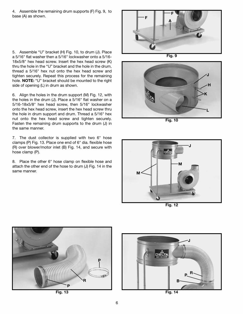
4. Assemble the remaining drum supports (F) Fig. 9, tobase (A) as shown.
5. Assemble “U” bracket (H) Fig. 10, to drum (J). Placea 5/16" flat washer then a 5/16" lockwasher onto a 5/16-18x5/8" hex head screw. Insert the hex head screw (K)thru the hole in the “U” bracket and the hole in the drum,thread a 5/16" hex nut onto the hex head screw andtighten securely. Repeat this process for the remaininghole. NOTE: “U” bracket should be mounted to the rightside of opening (L) in drum as shown.
6. Align the holes in the drum support (M) Fig. 12, withthe holes in the drum (J). Place a 5/16" flat washer on a5/16-18x5/8" hex head screw, then 5/16" lockwasheronto the hex head screw, insert the hex head screw thruthe hole in drum support and drum. Thread a 5/16" hexnut onto the hex head screw and tighten securely.Fasten the remaining drum supports to the drum (J) inthe same manner.
7. The dust collector is supplied with two 6" hoseclamps (P) Fig. 13. Place one end of 6" dia. flexible hose(R) over blower/motor inlet (B) Fig. 14, and secure withhose clamp (P).
8. Place the other 6" hose clamp on flexible hose andattach the other end of the hose to drum (J) Fig. 14 in thesame manner.
Fig. 14
F
A
J
H
K
L
J
M
M
PR
P
J
RPB
F
7
Fig. 15
Fig. 16
Fig. 17
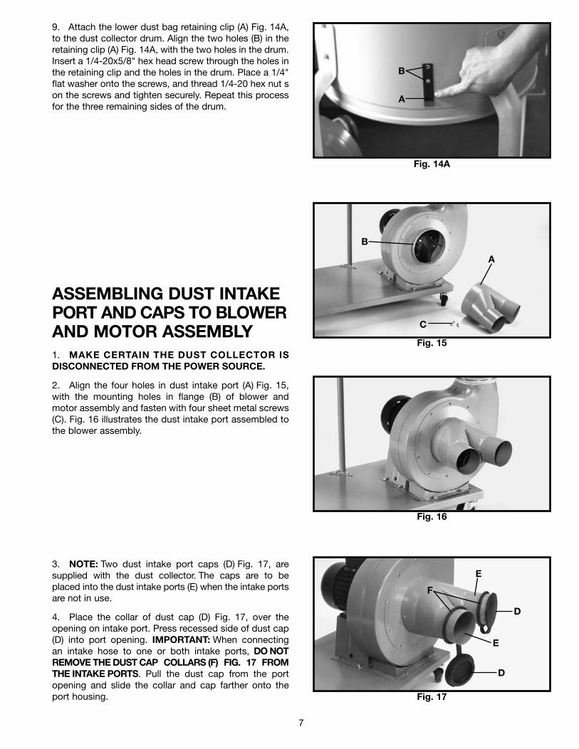
9. Attach the lower dust bag retaining clip (A) Fig. 14A,to the dust collector drum. Align the two holes (B) in theretaining clip (A) Fig. 14A, with the two holes in the drum.Insert a 1/4-20x5/8" hex head screw through the holes inthe retaining clip and the holes in the drum. Place a 1/4"flat washer onto the screws, and thread 1/4-20 hex nut son the screws and tighten securely. Repeat this processfor the three remaining sides of the drum.
ASSEMBLING DUST INTAKEPORT AND CAPS TO BLOWERAND MOTOR ASSEMBLY1. MAKE CERTAIN THE DUST COLLECTOR ISDISCONNECTED FROM THE POWER SOURCE.
2. Align the four holes in dust intake port (A) Fig. 15,with the mounting holes in flange (B) of blower andmotor assembly and fasten with four sheet metal screws(C). Fig. 16 illustrates the dust intake port assembled tothe blower assembly.
3. NOTE: Two dust intake port caps (D) Fig. 17, aresupplied with the dust collector. The caps are to beplaced into the dust intake ports (E) when the intake portsare not in use.
4. Place the collar of dust cap (D) Fig. 17, over theopening on intake port. Press recessed side of dust cap(D) into port opening. IMPORTANT: When connectingan intake hose to one or both intake ports, DO NOTREMOVE THE DUST CAP COLLARS (F) FIG. 17 FROMTHE INTAKE PORTS. Pull the dust cap from the portopening and slide the collar and cap farther onto theport housing.
A
B
C
E
D
E
D
F
Fig. 14A
A
B
8
Fig. 18
Fig. 19
Fig. 22
Fig. 20
Fig. 21
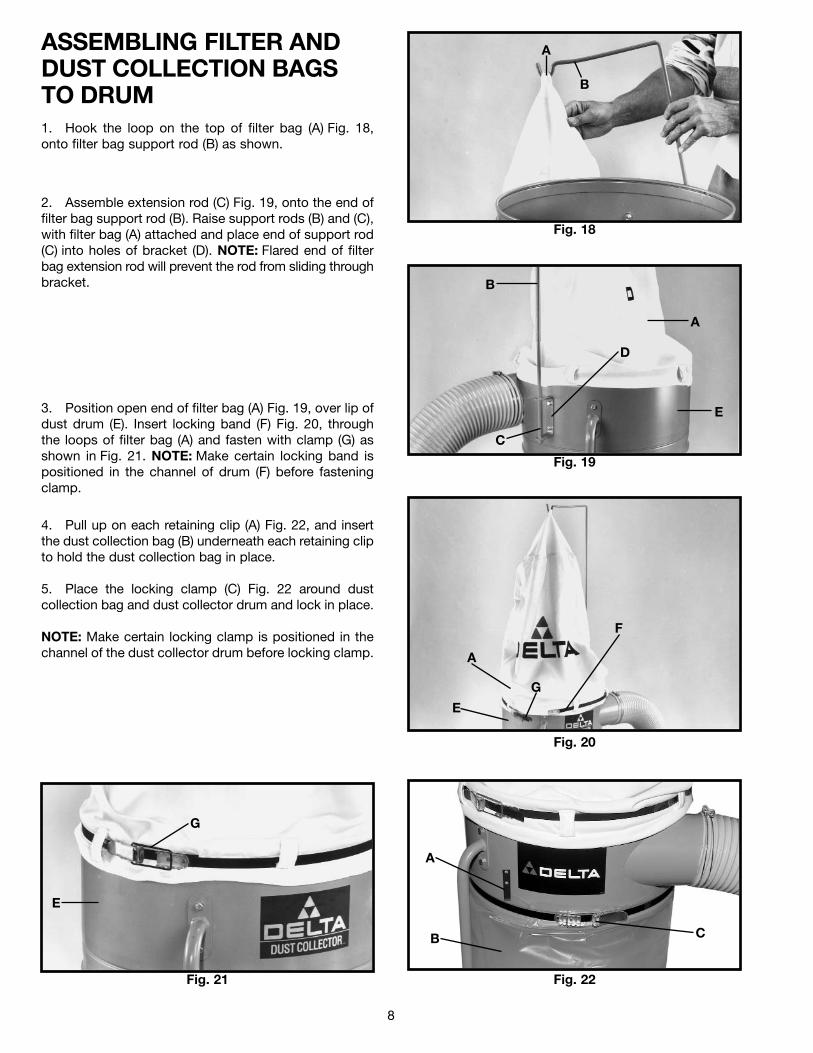
ASSEMBLING FILTER ANDDUST COLLECTION BAGSTO DRUM1. Hook the loop on the top of filter bag (A) Fig. 18,onto filter bag support rod (B) as shown.
2. Assemble extension rod (C) Fig. 19, onto the end offilter bag support rod (B). Raise support rods (B) and (C),with filter bag (A) attached and place end of support rod(C) into holes of bracket (D). NOTE: Flared end of filterbag extension rod will prevent the rod from sliding throughbracket.
3. Position open end of filter bag (A) Fig. 19, over lip ofdust drum (E). Insert locking band (F) Fig. 20, throughthe loops of filter bag (A) and fasten with clamp (G) asshown in Fig. 21. NOTE: Make certain locking band ispositioned in the channel of drum (F) before fasteningclamp.
4. Pull up on each retaining clip (A) Fig. 22, and insertthe dust collection bag (B) underneath each retaining clipto hold the dust collection bag in place.
5. Place the locking clamp (C) Fig. 22 around dustcollection bag and dust collector drum and lock in place.
NOTE: Make certain locking clamp is positioned in thechannel of the dust collector drum before locking clamp.
A
B
B
A
E
C
D
G
A
E
F
G
E
A
B C
9
Fig. 23
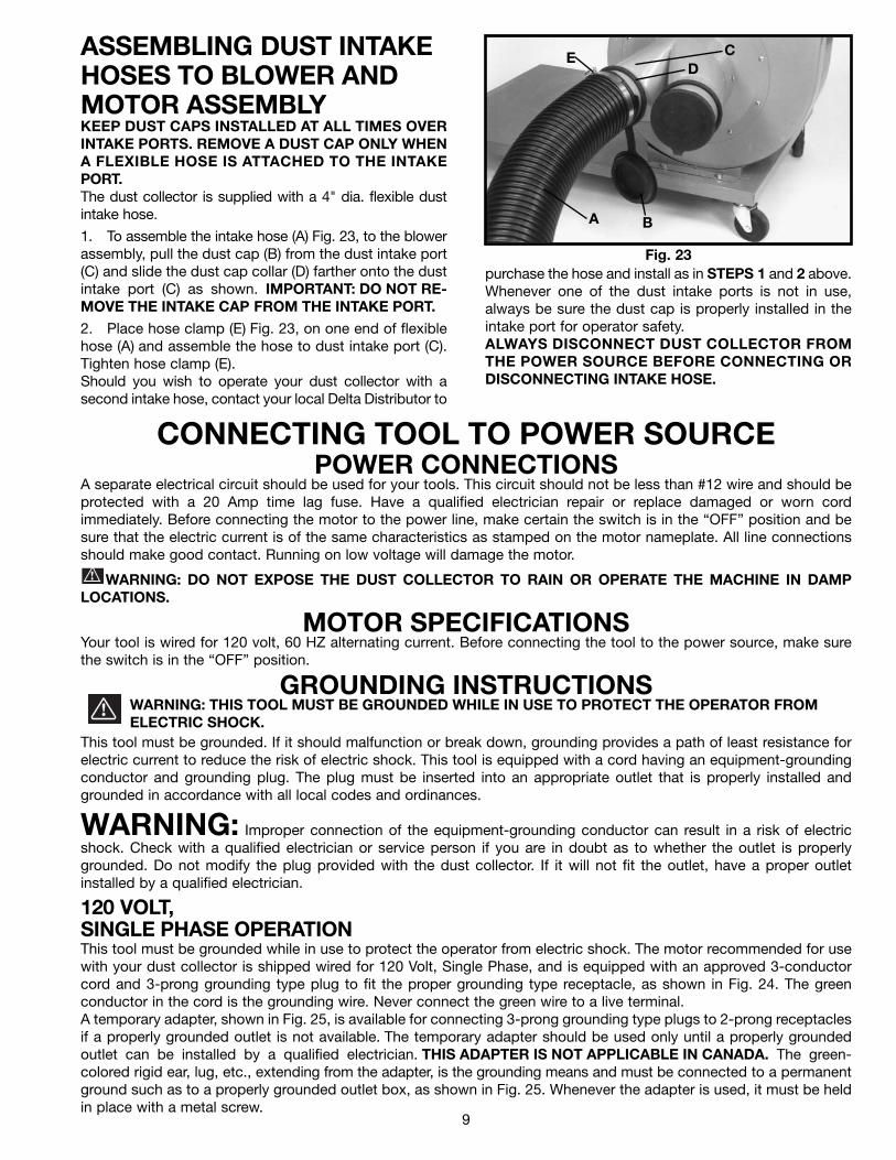
ASSEMBLING DUST INTAKEHOSES TO BLOWER ANDMOTOR ASSEMBLYKEEP DUST CAPS INSTALLED AT ALL TIMES OVERINTAKE PORTS. REMOVE A DUST CAP ONLY WHENA FLEXIBLE HOSE IS ATTACHED TO THE INTAKEPORT.The dust collector is supplied with a 4" dia. flexible dustintake hose.
1. To assemble the intake hose (A) Fig. 23, to the blowerassembly, pull the dust cap (B) from the dust intake port(C) and slide the dust cap collar (D) farther onto the dustintake port (C) as shown. IMPORTANT: DO NOT RE-MOVE THE INTAKE CAP FROM THE INTAKE PORT.
2. Place hose clamp (E) Fig. 23, on one end of flexiblehose (A) and assemble the hose to dust intake port (C).Tighten hose clamp (E).Should you wish to operate your dust collector with asecond intake hose, contact your local Delta Distributor to
purchase the hose and install as in STEPS 1 and 2 above.Whenever one of the dust intake ports is not in use,always be sure the dust cap is properly installed in theintake port for operator safety.ALWAYS DISCONNECT DUST COLLECTOR FROMTHE POWER SOURCE BEFORE CONNECTING ORDISCONNECTING INTAKE HOSE.
CONNECTING TOOL TO POWER SOURCEPOWER CONNECTIONS
A separate electrical circuit should be used for your tools. This circuit should not be less than #12 wire and should beprotected with a 20 Amp time lag fuse. Have a qualified electrician repair or replace damaged or worn cordimmediately. Before connecting the motor to the power line, make certain the switch is in the “OFF” position and besure that the electric current is of the same characteristics as stamped on the motor nameplate. All line connectionsshould make good contact. Running on low voltage will damage the motor.
WARNING: DO NOT EXPOSE THE DUST COLLECTOR TO RAIN OR OPERATE THE MACHINE IN DAMPLOCATIONS.
MOTOR SPECIFICATIONSYour tool is wired for 120 volt, 60 HZ alternating current. Before connecting the tool to the power source, make surethe switch is in the “OFF” position.
GROUNDING INSTRUCTIONSWARNING: THIS TOOL MUST BE GROUNDED WHILE IN USE TO PROTECT THE OPERATOR FROMELECTRIC SHOCK.
This tool must be grounded. If it should malfunction or break down, grounding provides a path of least resistance forelectric current to reduce the risk of electric shock. This tool is equipped with a cord having an equipment-groundingconductor and grounding plug. The plug must be inserted into an appropriate outlet that is properly installed andgrounded in accordance with all local codes and ordinances.
WARNING: Improper connection of the equipment-grounding conductor can result in a risk of electricshock. Check with a qualified electrician or service person if you are in doubt as to whether the outlet is properlygrounded. Do not modify the plug provided with the dust collector. If it will not fit the outlet, have a proper outletinstalled by a qualified electrician.
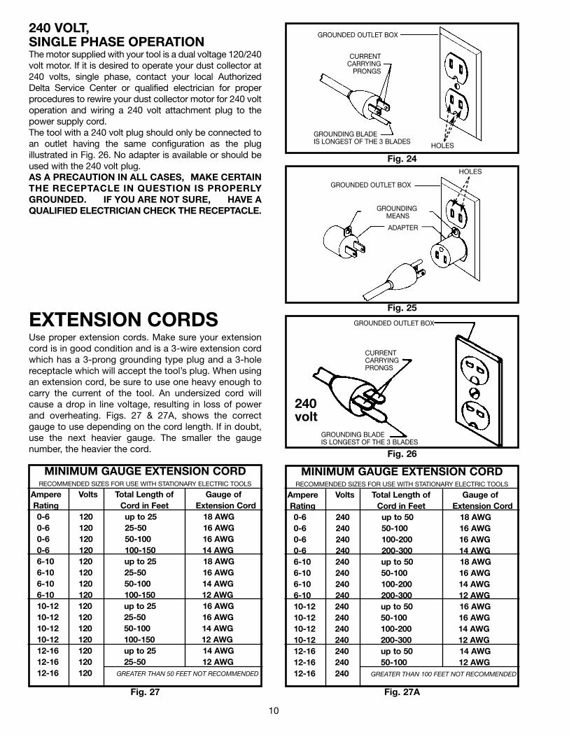
120 VOLT,SINGLE PHASE OPERATIONThis tool must be grounded while in use to protect the operator from electric shock. The motor recommended for usewith your dust collector is shipped wired for 120 Volt, Single Phase, and is equipped with an approved 3-conductorcord and 3-prong grounding type plug to fit the proper grounding type receptacle, as shown in Fig. 24. The greenconductor in the cord is the grounding wire. Never connect the green wire to a live terminal.A temporary adapter, shown in Fig. 25, is available for connecting 3-prong grounding type plugs to 2-prong receptaclesif a properly grounded outlet is not available. The temporary adapter should be used only until a properly groundedoutlet can be installed by a qualified electrician. THIS ADAPTER IS NOT APPLICABLE IN CANADA. The green-colored rigid ear, lug, etc., extending from the adapter, is the grounding means and must be connected to a permanentground such as to a properly grounded outlet box, as shown in Fig. 25. Whenever the adapter is used, it must be heldin place with a metal screw.
A B
ED
C
10
Use proper extension cords. Make sure your extensioncord is in good condition and is a 3-wire extension cordwhich has a 3-prong grounding type plug and a 3-holereceptacle which will accept the tool’s plug. When usingan extension cord, be sure to use one heavy enough tocarry the current of the tool. An undersized cord willcause a drop in line voltage, resulting in loss of powerand overheating. Figs. 27 & 27A, shows the correctgauge to use depending on the cord length. If in doubt,use the next heavier gauge. The smaller the gaugenumber, the heavier the cord.
EXTENSION CORDS
Fig. 24
GROUNDED OUTLET BOX
CURRENTCARRYING
PRONGS
GROUNDING BLADEIS LONGEST OF THE 3 BLADES
HOLES
Fig. 25
GROUNDED OUTLET BOX
GROUNDINGMEANS
ADAPTER
HOLES
GROUNDED OUTLET BOX
CURRENT CARRYINGPRONGS
GROUNDING BLADEIS LONGEST OF THE 3 BLADES
Fig. 26
240volt
240 VOLT,SINGLE PHASE OPERATIONThe motor supplied with your tool is a dual voltage 120/240volt motor. If it is desired to operate your dust collector at240 volts, single phase, contact your local AuthorizedDelta Service Center or qualified electrician for properprocedures to rewire your dust collector motor for 240 voltoperation and wiring a 240 volt attachment plug to thepower supply cord.The tool with a 240 volt plug should only be connected toan outlet having the same configuration as the plugillustrated in Fig. 26. No adapter is available or should beused with the 240 volt plug.AS A PRECAUTION IN ALL CASES, MAKE CERTAINTHE RECEPTACLE IN QUESTION IS PROPERLYGROUNDED. IF YOU ARE NOT SURE, HAVE AQUALIFIED ELECTRICIAN CHECK THE RECEPTACLE.
Fig. 27
MINIMUM GAUGE EXTENSION CORDRECOMMENDED SIZES FOR USE WITH STATIONARY ELECTRIC TOOLS
Ampere Volts Total Length of Gauge ofRating Cord in Feet Extension Cord0-6 120 up to 25 18 AWG0-6 120 25-50 16 AWG0-6 120 50-100 16 AWG0-6 120 100-150 14 AWG6-10 120 up to 25 18 AWG6-10 120 25-50 16 AWG6-10 120 50-100 14 AWG6-10 120 100-150 12 AWG 10-12 120 up to 25 16 AWG10-12 120 25-50 16 AWG10-12 120 50-100 14 AWG10-12 120 100-150 12 AWG12-16 120 up to 25 14 AWG12-16 120 25-50 12 AWG 12-16 120 GREATER THAN 50 FEET NOT RECOMMENDED
MINIMUM GAUGE EXTENSION CORDRECOMMENDED SIZES FOR USE WITH STATIONARY ELECTRIC TOOLS
Ampere Volts Total Length of Gauge ofRating Cord in Feet Extension Cord0-6 240 up to 50 18 AWG0-6 240 50-100 16 AWG0-6 240 100-200 16 AWG0-6 240 200-300 14 AWG6-10 240 up to 50 18 AWG6-10 240 50-100 16 AWG6-10 240 100-200 14 AWG6-10 240 200-300 12 AWG 10-12 240 up to 50 16 AWG10-12 240 50-100 16 AWG10-12 240 100-200 14 AWG10-12 240 200-300 12 AWG12-16 240 up to 50 14 AWG12-16 240 50-100 12 AWG 12-16 240 GREATER THAN 100 FEET NOT RECOMMENDED
Fig. 27A
11
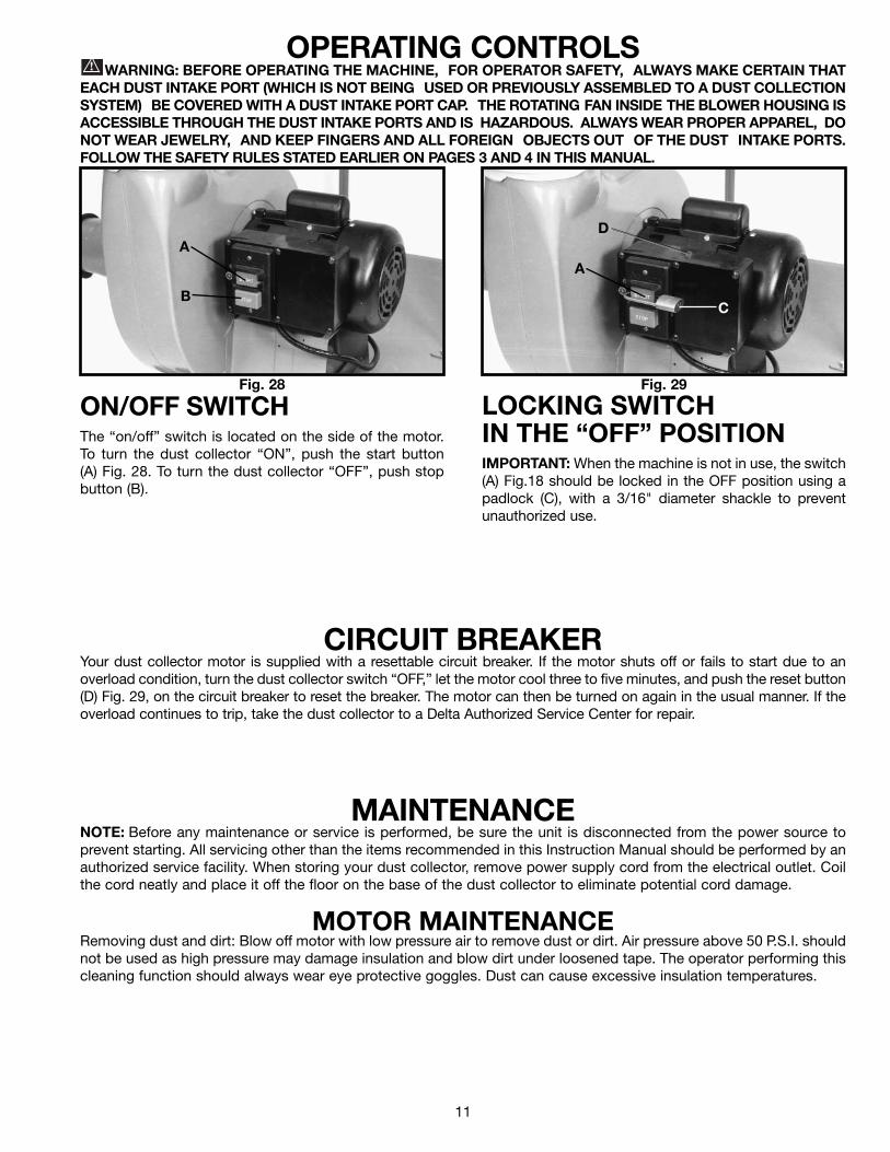
OPERATING CONTROLSWARNING: BEFORE OPERATING THE MACHINE, FOR OPERATOR SAFETY, ALWAYS MAKE CERTAIN THAT
EACH DUST INTAKE PORT (WHICH IS NOT BEING USED OR PREVIOUSLY ASSEMBLED TO A DUST COLLECTIONSYSTEM) BE COVERED WITH A DUST INTAKE PORT CAP. THE ROTATING FAN INSIDE THE BLOWER HOUSING ISACCESSIBLE THROUGH THE DUST INTAKE PORTS AND IS HAZARDOUS. ALWAYS WEAR PROPER APPAREL, DONOT WEAR JEWELRY, AND KEEP FINGERS AND ALL FOREIGN OBJECTS OUT OF THE DUST INTAKE PORTS.FOLLOW THE SAFETY RULES STATED EARLIER ON PAGES 3 AND 4 IN THIS MANUAL.
Fig. 28 Fig. 29
ON/OFF SWITCHThe “on/off” switch is located on the side of the motor.To turn the dust collector “ON”, push the start button(A) Fig. 28. To turn the dust collector “OFF”, push stopbutton (B).
LOCKING SWITCHIN THE “OFF” POSITIONIMPORTANT: When the machine is not in use, the switch(A) Fig.18 should be locked in the OFF position using apadlock (C), with a 3/16" diameter shackle to preventunauthorized use.
CIRCUIT BREAKERYour dust collector motor is supplied with a resettable circuit breaker. If the motor shuts off or fails to start due to anoverload condition, turn the dust collector switch “OFF,” let the motor cool three to five minutes, and push the reset button(D) Fig. 29, on the circuit breaker to reset the breaker. The motor can then be turned on again in the usual manner. If theoverload continues to trip, take the dust collector to a Delta Authorized Service Center for repair.
MAINTENANCENOTE: Before any maintenance or service is performed, be sure the unit is disconnected from the power source toprevent starting. All servicing other than the items recommended in this Instruction Manual should be performed by anauthorized service facility. When storing your dust collector, remove power supply cord from the electrical outlet. Coilthe cord neatly and place it off the floor on the base of the dust collector to eliminate potential cord damage.
MOTOR MAINTENANCERemoving dust and dirt: Blow off motor with low pressure air to remove dust or dirt. Air pressure above 50 P.S.I. shouldnot be used as high pressure may damage insulation and blow dirt under loosened tape. The operator performing thiscleaning function should always wear eye protective goggles. Dust can cause excessive insulation temperatures.
A
B
A
C
D

12
Two Year Limited WarrantyDelta will repair or replace, at its expense and at its option, any Delta machine, machine part, or machine accessory whichin normal use has proven to be defective in workmanship or material, provided that the customer returns the productprepaid to a Delta factory service center or authorized service station with proof of purchase of the product within twoyears and provides Delta with reasonable opportunity to verify the alleged defect by inspection. Delta may require thatelectric motors be returned prepaid to a motor manufacturer’s authorized station for inspection and repair or replacement.Delta will not be responsible for any asserted defect which has resulted from normal wear, misuse, abuse or repair oralteration made or specifically authorized by anyone other than an authorized Delta service facility or representative. Underno circumstances will Delta be liable for incidental or consequential damages resulting from defective products. Thiswarranty is Delta’s sole warranty and sets forth the customer’s exclusive remedy, with respect to defective products; allother warranties, express or implied, whether of merchantability, fitness for purpose, or otherwise, are expresslydisclaimed by Delta.
Printed in U.S.A.
PARTS, SERVICE OR WARRANTY ASSISTANCEAll Delta Machines and accessories are manufactured to high quality standards and are serviced by a networkof Porter-Cable • Delta Factory Service Centers and Delta Authorized Service Stations. To obtain additionalinformation regarding your Delta quality product or to obtain parts, service, warranty assistance, or the locationof the nearest service outlet, please call 1-800-223-7278 (In Canada call 1-800-463-3582).
ACCESSORIESA complete line of accessories is available from your Delta Supplier, Porter-Cable • Delta Factory Service Centers,and Delta Authorized Service Stations. Please visit our Web Site www.deltamachinery.com for a catalog orfor the name of your nearest supplier.
WARNING: Since accessories, other than those offered by Delta, have not been tested with this product, use of such accessories could be hazardous. For safest operation, only Delta recommended accessories should be used with this product.
The following are trademarks of PORTER-CABLE·DELTA (Las siguientes son marcas registradas de PORTER-CABLE S.A.): Auto-Set®,BAMMER®, B.O.S.S.®, Builder’s Saw®, Contractor’s Saw®, Contractor’s Saw II™, Delta®, DELTACRAFT®, DELTAGRAM™, Delta Series2000™, DURATRONIC™, Emc²™, FLEX®, Flying Chips™, FRAME SAW®, Homecraft®, INNOVATION THAT WORKS®, Jet-Lock®,JETSTREAM®, ‘kickstand®, LASERLOC®, MICRO-SET®, Micro-Set®, Midi Lathe™, MORTEN™, NETWORK™, OMNIJIG®, POCKETCUTTER®, PORTA-BAND®, PORTA-PLANE®, PORTER-CABLE®&(design), PORTER-CABLE®PROFESSIONAL POWER TOOLS, Posi-Matic®,Q-3®&(design), QUICKSAND®&(design), QUICKSET™, QUICKSET II®, QUICKSET PLUS™, RIPTIDE™&(design), SAFE GUARD II®, SAFE-LOC®, Sanding Center®, SANDTRAP®&(design), SAW BOSS®, Sawbuck™, Sidekick®, SPEED-BLOC®, SPEEDMATIC®, SPEEDTRONIC®,STAIR EASE®, The American Woodshop®&(design), The Lumber Company®&(design), THE PROFESSIONAL EDGE®, THE PROFESSIONALSELECT®, THIN-LINE™, TIGER®, TIGER CUB®, TIGER SAW®, TORQBUSTER®, TORQ-BUSTER®, TRU-MATCH™, TWIN-LITE®,UNIGUARD®, Unifence®, UNIFEEDER™, Unihead®, Uniplane™, Unirip®, Unisaw®, Univise®, Versa-Feeder®, VERSA-PLANE® , WHISPERSERIES®, WOODWORKER’S CHOICE™. Trademarks noted with ™ and ® are registered in the United States Patent and Trademark Office and may also be registered in othercountries. Las Marcas Registradas con el signo de ™ y ® son registradas por la Oficina de Registros y Patentes de los Estados Unidos ytambién pueden estar registradas en otros países.
PORTER-CABLE • DELTA SERVICE CENTERS(CENTROS DE SERVICIO DE PORTER-CABLE • DELTA)
Parts and Repair Service for Porter-Cable • Delta Machinery are Available at These Locations(Obtenga Refaccion de Partes o Servicio para su Herramienta en los Siguientes Centros de Porter-Cable • Delta)
Authorized Service Stations are located in many large cities. Telephone 800-438-2486 or 731-541-6042 for assistance locating one.Parts and accessories for Porter-Cable·Delta products should be obtained by contacting any Porter-Cable·Delta Distributor, AuthorizedService Center, or Porter-Cable·Delta Factory Service Center. If you do not have access to any of these, call 800-223-7278 and you willbe directed to the nearest Porter-Cable·Delta Factory Service Center. Las Estaciones de Servicio Autorizadas están ubicadas en muchasgrandes ciudades. Llame al 800-438-2486 ó al 731-541-6042 para obtener asistencia a fin de localizar una. Las piezas y los accesoriospara los productos Porter-Cable·Delta deben obtenerse poniéndose en contacto con cualquier distribuidor Porter-Cable·Delta, Centrode Servicio Autorizado o Centro de Servicio de Fábrica Porter-Cable·Delta. Si no tiene acceso a ninguna de estas opciones, llame al800-223-7278 y le dirigirán al Centro de Servicio de Fábrica Porter-Cable·Delta más cercano.
ARIZONATempe 85282 (Phoenix)2400 West Southern AvenueSuite 105Phone: (602) 437-1200Fax: (602) 437-2200
CALIFORNIAOntario 91761 (Los Angeles)3949A East Guasti RoadPhone: (909) 390-5555Fax: (909) 390-5554San Leandro 94577 (Oakland)3039 Teagarden StreetPhone: (510) 357-9762Fax: (510) 357-7939
COLORADOArvada 80003 (Denver)8175 Sheridan Blvd., Unit SPhone: (303) 487-1809Fax: (303) 487-1868
FLORIDADavie 33314 (Miami)4343 South State Rd. 7 (441)Unit #107Phone: (954) 321-6635Fax: (954) 321-6638
Tampa 33609 4538 W. Kennedy BoulevardPhone: (813) 877-9585Fax: (813) 289-7948
GEORGIAForest Park 30297 (Atlanta)5442 Frontage Road,Suite 112Phone: (404) 608-0006Fax: (404) 608-1123
ILLINOISAddison 60101 (Chicago)400 South Rohlwing Rd.Phone: (630) 424-8805Fax: (630) 424-8895
Woodridge 60517 (Chicago)2033 West 75th StreetPhone: (630) 910-9200Fax: (630) 910-0360
MARYLANDElkridge 21075 (Baltimore)7397-102 Washington Blvd.Phone: (410) 799-9394Fax: (410) 799-9398
MASSACHUSETTSBraintree 02185 (Boston)719 Granite StreetPhone: (781) 848-9810Fax: (781) 848-6759Franklin 02038 (Boston)Franklin Industrial Park101E Constitution Blvd.Phone: (508) 520-8802Fax: (508) 528-8089
MICHIGANMadison Heights 48071 (Detroit)30475 Stephenson HighwayPhone: (248) 597-5000Fax: (248) 597-5004
MINNESOTAMinneapolis 554295522 Lakeland Avenue NorthPhone: (763) 561-9080Fax: (763) 561-0653
MISSOURINorth Kansas City 641161141 Swift AvenueP.O. Box 12393Phone: (816) 221-2070Fax: (816) 221-2897
St. Louis 631197574 Watson RoadPhone: (314) 968-8950Fax: (314) 968-2790
NEW YORKFlushing 11365-1595 (N.Y.C.)175-25 Horace Harding Expwy.Phone: (718) 225-2040Fax: (718) 423-9619
NORTH CAROLINACharlotte 282709129 Monroe Road, Suite 115Phone: (704) 841-1176Fax: (704) 708-4625
OHIOColumbus 432144560 Indianola AvenuePhone: (614) 263-0929Fax: (614) 263-1238
Cleveland 441258001 Sweet Valley DriveUnit #19Phone: (216) 447-9030Fax: (216) 447-3097
OREGONPortland 972304916 NE 122 nd Ave.Phone: (503) 252-0107Fax: (503) 252-2123
PENNSYLVANIAWillow Grove 19090520 North York RoadPhone: (215) 658-1430Fax: (215) 658-1433
TEXASCarrollton 75006 (Dallas)1300 Interstate 35 N, Suite 112Phone: (972) 446-2996Fax: (972) 446-8157
Houston 77055West 10 Business Center1008 Wirt Road, Suite 120Phone: (713) 682-0334Fax: (713) 682-4867
WASHINGTONAuburn 98001(Seattle)3320 West Valley HWY, NorthBuilding D, Suite 111Phone: (253) 333-8353Fax: (253) 333-9613
Printed in U.S.A.
CANADIAN PORTER-CABLE • DELTA SERVICE CENTERSALBERTABay 6, 2520-23rd St. N.E.Calgary, AlbertaT2E 8L2Phone: (403) 735-6166Fax: (403) 735-6144
BRITISH COLUMBIA8520 Baxter PlaceBurnaby, B.C.V5A 4T8Phone: (604) 420-0102Fax: (604) 420-3522
MANITOBA1699 Dublin AvenueWinnipeg, ManitobaR3H 0H2Phone: (204) 633-9259Fax: (204) 632-1976
ONTARIO505 Southgate DriveGuelph, OntarioN1H 6M7Phone: (519) 836-2840Fax: (519) 767-4131
QUÉBEC1515 ave.St-Jean Baptiste,Québec, QuébecG2E 5E2Phone: (418) 877-7112Fax: (418) 877-7123
1447, BeginSt-Laurent, (Montréal),QuébecH4R 1V8Phone: (514) 336-8772Fax: (514) 336-3505