Embed Size (px)
Citation preview
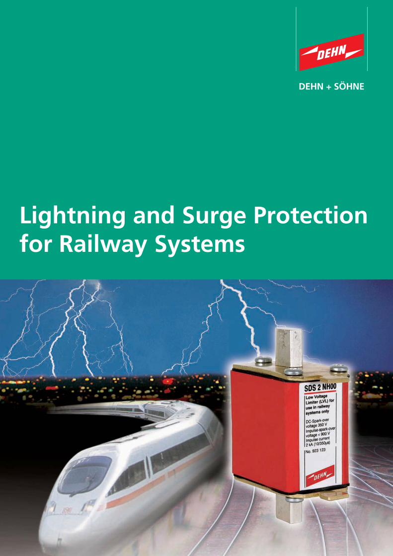
Lightning and Surge Protection for Railway Systems
elektrotechnik und informationstechnike&i
praxis+wissen
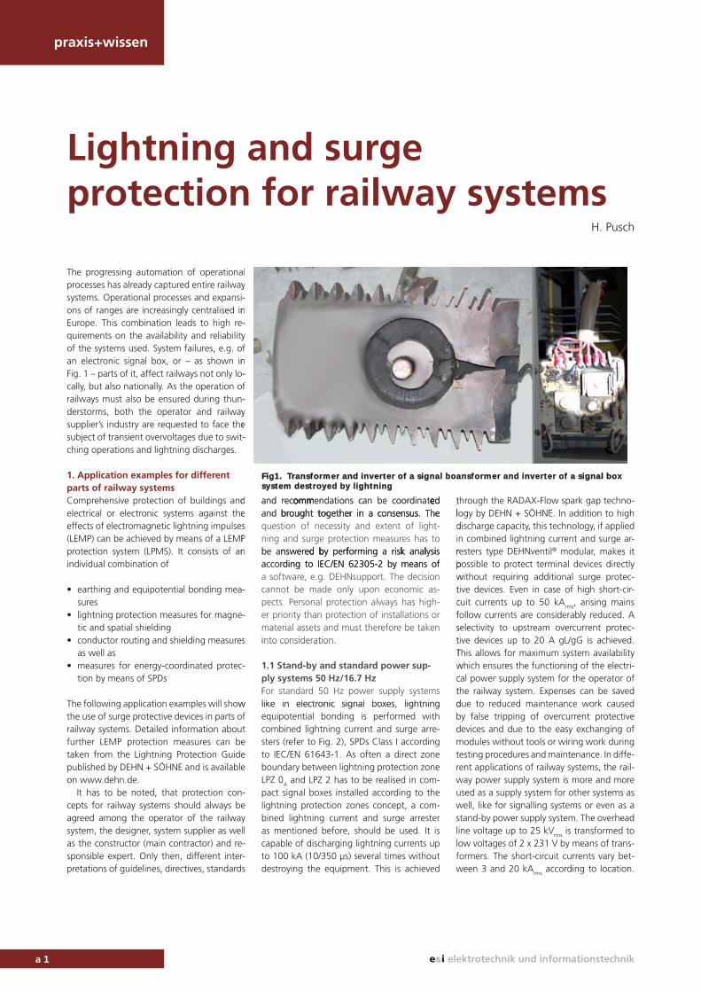
The progressing automation of operational processes has already captured entire railway systems. Operational processes and expansi-ons of ranges are increasingly centralised in Europe. This combination leads to high re-quirements on the availability and reliability of the systems used. System failures, e.g. of an electronic signal box, or – as shown in Fig. 1 – parts of it, affect railways not only lo-cally, but also nationally. As the operation of railways must also be ensured during thun-derstorms, both the operator and railway supplier’s industry are requested to face the subject of transient overvoltages due to swit-ching operations and lightning discharges.
1. Application examples for differentparts of railway systemsComprehensive protection of buildings and electrical or electronic systems against the effects of electromagnetic lightning impulses (LEMP) can be achieved by means of a LEMP protection system (LPMS). It consists of an individual combination of
• earthing and equipotential bonding mea-sures
• lightning protection measures for magne-tic and spatial shielding
• conductor routing and shielding measuresas well as
• measures for energy-coordinated protec-tion by means of SPDs
The following application examples will show the use of surge protective devices in parts of railway systems. Detailed information about further LEMP protection measures can be taken from the Lightning Protection Guide published by DEHN + SÖHNE and is available on www.dehn.de.
It has to be noted, that protection con-cepts for railway systems should always be agreed among the operator of the railway system, the designer, system supplier as well as the constructor (main contractor) and re-sponsible expert. Only then, different inter-pretations of guidelines, directives, standards
and recommendations can be coordinated and brought together in a consensus. The question of necessity and extent of light-ning and surge protection measures has to be answered by performing a risk analysis according to IEC/EN 62305-2 by means of a software, e.g. DEHNsupport. The decision cannot be made only upon economic as-pects. Personal protection always has high-er priority than protection of installations or material assets and must therefore be taken into consideration.
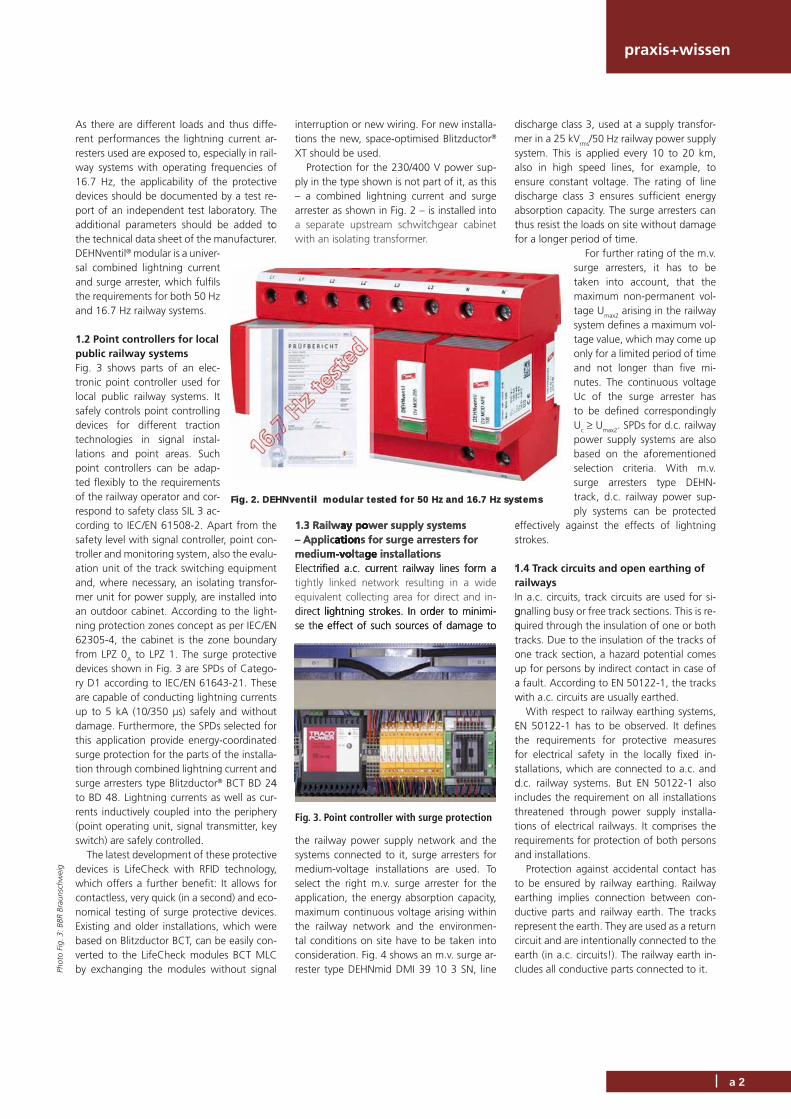
1.1 Stand-by and standard power sup-ply systems 50 Hz/16.7 HzFor standard 50 Hz power supply systems like in electronic signal boxes, lightning equipotential bonding is performed with combined lightning current and surge arre-sters (refer to Fig. 2), SPDs Class I according to IEC/EN 61643-1. As often a direct zone boundary between lightning protection zone LPZ 0
A and LPZ 2 has to be realised in com-pact signal boxes installed according to the lightning protection zones concept, a com-bined lightning current and surge arrester as mentioned before, should be used. It is capable of discharging lightning currents up to 100 kA (10/350 μs) several times without destroying the equipment. This is achieved
through the RADAX-Flow spark gap techno-logy by DEHN + SÖHNE. In addition to high discharge capacity, this technology, if applied in combined lightning current and surge ar-resters type DEHNventil® modular, makes it possible to protect terminal devices directly without requiring additional surge protec-tive devices. Even in case of high short-cir-cuit currents up to 50 kArms, arising mains follow currents are considerably reduced. A selectivity to upstream overcurrent protec-tive devices up to 20 A gL/gG is achieved. This allows for maximum system availability which ensures the functioning of the electri-cal power supply system for the operator of the railway system. Expenses can be saved due to reduced maintenance work caused by false tripping of overcurrent protective devices and due to the easy exchanging of modules without tools or wiring work during testing procedures and maintenance. In diffe-rent applications of railway systems, the rail-way power supply system is more and more used as a supply system for other systems as well, like for signalling systems or even as a stand-by power supply system. The overhead line voltage up to 25 kV
rms is transformed to low voltages of 2 x 231 V by means of trans-formers. The short-circuit currents vary bet-ween 3 and 20 kArms according to location.
Lightning and surge protection for railway systems
H. Pusch
a 1
ly-n-yfn -f-ye -
desPn
-
-
s
-
w
and recoomomo mmenmmm dations can be coordinateed eeeand brbrougougoughtht togtogtogethethererer inin a ca ca consonsonsensensensusus.us. Th Theee question of necessity and extent of light-ning and surge protection measures has to be annswer dded bbby perfffor iming a i ri kksk analllysiis according to IEC/EN 62305-2 by means ofa software, e.g. DEHNsupport. The decisioncannot be made only upon economic as-pects. Personal protection always has high-er priority than protection of installations ormaterial assets and must therefore be takeninto consideration.
1.1 Stand-by and standard power sup-ply systems 50 Hz/16.7 HzFor standard 50 Hz power supply systems like in electronic signal boxes lightning
tllldirpwtcfstTwctd
Fig1. Transformer and inverter of a signal boansformer and inverter of a signal box system destroyed by lightning
praxis+wissen
As there are different loads and thus diffe-rent performances the lightning current ar-resters used are exposed to, especially in rail-way systems with operating frequencies of 16.7 Hz, the applicability of the protective devices should be documented by a test re-port of an independent test laboratory. The additional parameters should be added to the technical data sheet of the manufacturer. DEHNventil® modular is a univer-sal combined lightning current and surge arrester, which fulfils the requirements for both 50 Hz and 16.7 Hz railway systems.
1.2 Point controllers for local public railway systems Fig. 3 shows parts of an elec-tronic point controller used for local public railway systems. It safely controls point controlling devices for different traction technologies in signal instal-lations and point areas. Such point controllers can be adap-ted flexibly to the requirements of the railway operator and cor-respond to safety class SIL 3 ac-cording to IEC/EN 61508-2. Apart from the safety level with signal controller, point con-troller and monitoring system, also the evalu-ation unit of the track switching equipment and, where necessary, an isolating transfor-mer unit for power supply, are installed into an outdoor cabinet. According to the light-ning protection zones concept as per IEC/EN 62305-4, the cabinet is the zone boundary from LPZ 0
A to LPZ 1. The surge protective devices shown in Fig. 3 are SPDs of Catego-ry D1 according to IEC/EN 61643-21. These are capable of conducting lightning currents up to 5 kA (10/350 μs) safely and without damage. Furthermore, the SPDs selected for this application provide energy-coordinated surge protection for the parts of the installa-tion through combined lightning current and surge arresters type Blitzductor® BCT BD 24 to BD 48. Lightning currents as well as cur-rents inductively coupled into the periphery (point operating unit, signal transmitter, key switch) are safely controlled.
The latest development of these protective devices is LifeCheck with RFID technology, which offers a further benefit: It allows for contactless, very quick (in a second) and eco-nomical testing of surge protective devices. Existing and older installations, which were based on Blitzductor BCT, can be easily con-verted to the LifeCheck modules BCT MLC by exchanging the modules without signal
interruption or new wiring. For new installa-tions the new, space-optimised Blitzductor® XT should be used.
Protection for the 230/400 V power sup-ply in the type shown is not part of it, as this – a combined lightning current and surgearrester as shown in Fig. 2 – is installed into a separate upstream schwitchgear cabinet with an isolating transformer.
1.3 Railway power supply systems – Applications for surge arresters formedium-voltage installationsElectrified a.c. current railway lines form a tightly linked network resulting in a wide equivalent collecting area for direct and in-direct lightning strokes. In order to minimi-se the effect of such sources of damage to
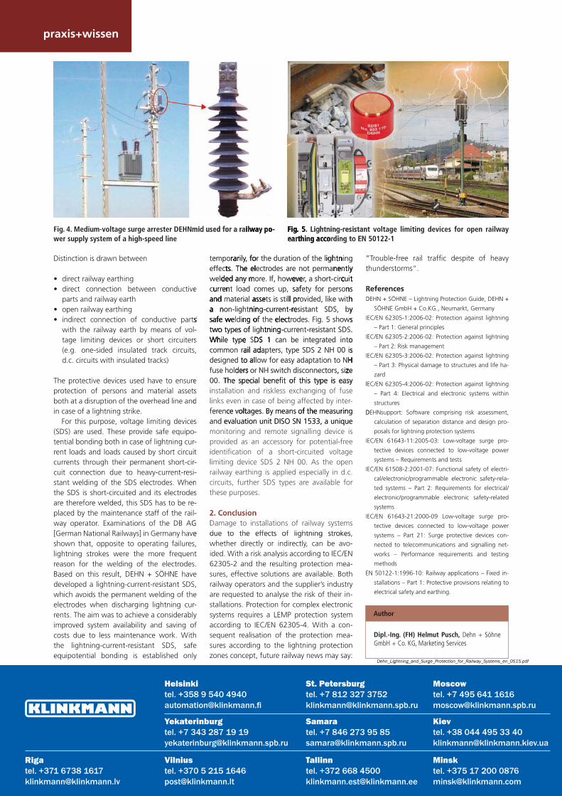
the railway power supply network and the systems connected to it, surge arresters for medium-voltage installations are used. To select the right m.v. surge arrester for the application, the energy absorption capacity, maximum continuous voltage arising within the railway network and the environmen-tal conditions on site have to be taken into consideration. Fig. 4 shows an m.v. surge ar-rester type DEHNmid DMI 39 10 3 SN, line
discharge class 3, used at a supply transfor-mer in a 25 kV
rms/50 Hz railway power supply system. This is applied every 10 to 20 km, also in high speed lines, for example, to ensure constant voltage. The rating of line discharge class 3 ensures sufficient energy absorption capacity. The surge arresters can thus resist the loads on site without damage for a longer period of time.
For further rating of the m.v. surge arresters, it has to be taken into account, that the maximum non-permanent vol-tage U
max2 arising in the railway system defines a maximum vol-tage value, which may come up only for a limited period of time and not longer than five mi-nutes. The continuous voltage Uc of the surge arrester has to be defined correspondingly Uc Umax2. SPDs for d.c. railwaypower supply systems are also based on the aforementioned selection criteria. With m.v. surge arresters type DEHN-track, d.c. railway power sup-ply systems can be protected
effectively against the effects of lightning strokes.
1.4 Track circuits and open earthing of railwaysIn a.c. circuits, track circuits are used for si-gnalling busy or free track sections. This is re-quired through the insulation of one or both tracks. Due to the insulation of the tracks of one track section, a hazard potential comes up for persons by indirect contact in case of a fault. According to EN 50122-1, the tracks with a.c. circuits are usually earthed.
With respect to railway earthing systems, EN 50122-1 has to be observed. It defines the requirements for protective measures for electrical safety in the locally fixed in-stallations, which are connected to a.c. and d.c. railway systems. But EN 50122-1 also includes the requirement on all installations threatened through power supply installa-tions of electrical railways. It comprises the requirements for protection of both persons and installations.
Protection against accidental contact has to be ensured by railway earthing. Railway earthing implies connection between con-ductive parts and railway earth. The tracks represent the earth. They are used as a return circuit and are intentionally connected to the earth (in a.c. circuits!). The railway earth in-cludes all conductive parts connected to it.
Fig. 3. Point controller with surge protection
Phot
o Fi
g. 3
: BBR
Bra
unsc
hwei
g
a 2
o.
e--t -o -
Ny e-es t r d -d 4
a separate upstream schwitchgear cabinet with an isolating transformer.
1.3 Railwayayay yay poopowpoop er supply systems– Applicaaaaatiotiotiott onnns nn for surge arresters formediumm-vovo-vo-vooltage ge installationsElectrrrifieified ad a c.c..c. cucu currerrerrentntnt rairailwalway ly lineines fs formormorm aa a tightly linked network resulting in a wide equivalent collecting area for direct and in-directt lilili hhtght ining sttrokkkes I. In o ddrde tr to mi iini imi-se thee effect of such sources of damage to
tf
es
111rIgqtouaw
Etfsd
Fig. 2. DEHNventil modular tested for 50 Hz and 16.7 Hz systems
praxis+wissen
Distinction is drawn between
• direct railway earthing• direct connection between conductive
parts and railway earth• open railway earthing• indirect connection of conductive parts
with the railway earth by means of vol-tage limiting devices or short circuiters (e.g. one-sided insulated track circuits, d.c. circuits with insulated tracks)
The protective devices used have to ensure protection of persons and material assets both at a disruption of the overhead line and in case of a lightning strike.
For this purpose, voltage limiting devices (SDS) are used. These provide safe equipo-tential bonding both in case of lightning cur-rent loads and loads caused by short circuit currents through their permanent short-cir-cuit connection due to heavy-current-resi-stant welding of the SDS electrodes. When the SDS is short-circuited and its electrodes are therefore welded, this SDS has to be re-placed by the maintenance staff of the rail-way operator. Examinations of the DB AG [German National Railways] in Germany have shown that, opposite to operating failures, lightning strokes were the more frequent reason for the welding of the electrodes. Based on this result, DEHN + SÖHNE have developed a lightning-current-resistant SDS, which avoids the permanent welding of the electrodes when discharging lightning cur-rents. The aim was to achieve a considerably improved system availability and saving of costs due to less maintenance work. With the lightning-current-resistant SDS, safe equipotential bonding is established only
temporarily, for the duration of the lightning effects. The electrodes are not permanently welded any more. If, however, a short-circuit current load comes up, safety for persons and material assets is still provided, like with a non-lightning-current-resistant SDS, by safe welding of the electrodes. Fig. 5 shows two types of lightning-current-resistant SDS. While type SDS 1 can be integrated into common rail adapters, type SDS 2 NH 00 is designed to allow for easy adaptation to NH fuse holders or NH switch disconnectors, size 00. The special benefit of this type is easyinstallation and riskless exchanging of fuse links even in case of being affected by inter-ference voltages. By means of the measuring and evaluation unit DISO SN 1533, a unique monitoring and remote signalling device is provided as an accessory for potential-free identification of a short-circuited voltage limiting device SDS 2 NH 00. As the open railway earthing is applied especially in d.c. circuits, further SDS types are available for these purposes.
2. ConclusionDamage to installations of railway systems due to the effects of lightning strokes, whether directly or indirectly, can be avo-ided. With a risk analysis according to IEC/EN 62305-2 and the resulting protection mea-sures, effective solutions are available. Both railway operators and the supplier’s industry are requested to analyse the risk of their in-stallations. Protection for complex electronic systems requires a LEMP protection system according to IEC/EN 62305-4. With a con-sequent realisation of the protection mea-sures according to the lightning protection zones concept, future railway news may say:
“Trouble-free rail traffic despite of heavy thunderstorms“.
ReferencesDEHN + SÖHNE – Lightning Protection Guide, DEHN +
SÖHNE GmbH + Co.KG., Neumarkt, Germany
IEC/EN 62305-1:2006-02: Protection against lightning
– Part 1: General principles
IEC/EN 62305-2:2006-02: Protection against lightning
– Part 2: Risk management
IEC/EN 62305-3:2006-02: Protection against lightning
– Part 3: Physical damage to structures and life ha-
zard
IEC/EN 62305-4:2006-02: Protection against lightning
– Part 4: Electrical and electronic systems within
structures
DEHNsupport: Software comprising risk assessment,
calculation of separation distance and design pro-
posals for lightning protection systems
IEC/EN 61643-11:2005-03: Low-voltage surge pro-
tective devices connected to low-voltage power
systems – Requirements and tests
IEC/EN 61508-2:2001-07: Functional safety of electri-
cal/electronic/programmable electronic safety-rela-
ted systems – Part 2: Requirements for electrical/
electronic/programmable electronic safety-related
systems
IEC/EN 61643-21:2000-09 Low-voltage surge pro-
tective devices connected to low-voltage power
systems – Part 21: Surge protective devices con-
nected to telecommunications and signalling net-
works – Performance requirements and testing
methods
EN 50122-1:1996-10: Railway applications – Fixed in-
stallations – Part 1: Protective provisions relating to
electrical safety and earthing.
Fig. 4. Medium-voltage surge arrester DEHNmid used for a railway po-wer supply system of a high-speed line
Fig. 5. Lightning-resistant voltage limiting devices for open railway earthing according to EN 50122-1
Dipl.-Ing. (FH) Helmut Pusch, Dehn + Söhne GmbH + Co. KG, Marketing Services
Author
e
sss s-s,
esd
s--t--ns--
Ge
temporrrrarariarraa ly, fooofooor the duration of the liiighttghtgh nninnnnn geffecttttsss. s TheTheTheThehe eleell electrodes are not permaneneneneentllllyy yyyweldeddeddededd an anany mmmy my ore. If, howweveeeveeveever, a short-circcccccuitttttcuuuruu renenennnt load comes up, safffef ty for personns nnandandandddd material assasaaa sesetsesesse s is stillllll pl pl prrovrr ided, like withhhhh a na na naaa on-lightnnnnininginn -current-rereresr istant SDS, byy ysafsasafafffe we we we we we weldee inngngnnn ofofofoo the eeeeeeeleclecleccctttrott des. Fig. 5 showsss stwowowoww typespesssss offfff lighthttnnninnggg-cg urrent-resistant SDS.. WhiWWhWhiWhh le typeee See DSDSDS 111 can be integrated intoocommon raaaaillil lil adaadaddda pters, type SDS 2 NH 00 issssdesigned ttoto tt alallaaa ow for easy adaptation to NHHH HHHfuse holdddersersss or NH switch disconnectors, s, izzezzz 00. ThThe se se specpecpecialial be benefinefit ot ot of tf thishis tyty typepepe isis easeaseasyyyinstallation and riskless exchanging of fuselinks even in case of being affected by inter-ferencce v ltoltoltages. BBy means fofof ththethe measu irinringand eevaluation unit DISO SN 1533, a uniquemonitoring and remote signalling device isprovided as an accessory for potential-freeidentification of a short-circuited voltagelimiting device SDS 2 NH 00. As the openrailway earthing is applied especially in d.c.circuits, further SDS types are available forthese purposes.
2. ConclusionDamage to installations of railway systemsdue to the effects of lightning strokes
“t
RD
I
I
I
II
D
I
I
I
mid used for a raiiiilwaway po--o FigFigFFigg 5. 5. 5. . Lightning-resistaneareareareearthittt ng g accaccaccaaccordoooo ing to EN
Samaratel. +7 846 273 95 [email protected]
Yekaterinburgtel. +7 343 287 19 [email protected]
St. Petersburgtel. +7 812 327 [email protected]
Moscowtel. +7 495 641 [email protected]
Helsinkitel. +358 9 540 [email protected]
Vilniustel. +370 5 215 [email protected]
Rigatel. +371 6738 [email protected]
Мinsktel. +375 17 200 [email protected]
Tallinntel. +372 668 [email protected]
Кievtel. +38 044 495 33 [email protected]
Dehn_Lightning_and_Surge_Protection_for_Railway_Systems_en_0515.pdf