Embed Size (px)
Citation preview
Lightning and surgeprotection - basic principles
October 2016AN904-1002 Rev I
Application noteMTL surge protection
CONTENTS ........................................................................................................................................................................... Page
1 INTRODUCTION ...........................................................................................................................................................................................................................................................1 1.1 The need for surge protection .........................................................................................................................................................................................................1 1.2 Surge protection devices (SPDs) ........................................................................................................................................... ..........................................................1
2 LIGHTNING ........................................................................................................................................................................................... ........................................................................2 2.1 Introduction ............................................................................................................................................................................ ................................................................2 2.2 Generation of atmospheric discharges .........................................................................................................................................................................................2 2.3 Lightning conductors and buildings ....................................................................................................................................... ......................................................2 2.4 Lightning-induced transients .................................................................................................................................................. .........................................................3 2.5 Transient specifications ......................................................................................................................................................... .............................................................3
3 SURGE PROTECTION COMPONENTS .............................................................................................................................................. ......................................................................4 3.1 Introduction ............................................................................................................................................................................ ................................................................4 3.2 Arc or carbon spark gaps ....................................................................................................................................................... ............................................................4 3.3 Gas discharge tubes ............................................................................................................................................................. ................................................................4 3.4 Zener diodes ......................................................................................................................................................................... ..................................................................5 3.5 Metal oxide varistors ............................................................................................................................................................................................................................5 3.6 Fuses ..................................................................................................................................................................................... .....................................................................6 3.7 Surge relays .......................................................................................................................................................................... ...................................................................6 3.8 Circuit breakers ..................................................................................................................................................................... .................................................................6 3.9 Multistage hybrid circuits ....................................................................................................................................................... ...........................................................6
4 SURGE PROTECTION DEVICES (SPDs) ............................................................................................................................................ ......................................................................6 4.1 Introduction ........................................................................................................................................................................... .................................................................6 4.2 Basic multistage hybrid circuits ............................................................................................................................................. ..........................................................6
5 APPLICATIONS..................................................................................................................................................................................... .........................................................................8 5.1 The need for protection ......................................................................................................................................................... ............................................................8 5.2 Loop protection – general ..................................................................................................................................................... ............................................................8 5.3 SPD selection – general ....................................................................................................................................................... ...............................................................8 5.4 Surge protection for industrial process systems ................................................................................................................... ....................................................8 5.5 Surge protection for building systems and communications networks ................................................................................. .........................................8 5.6 Specific applications ............................................................................................................................................................. ...............................................................8
6 EARTHING ................................................................................................................................................................................................................................................................... 16 6.1 Introduction ......................................................................................................................................................................................................................................... 16 6.2 Earthing ................................................................................................................................................................................................................................................. 16
7 MAINTENANCE ........................................................................................................................................................................................................................................................ 16 7.1 Introduction ........................................................................................................................................................................................................................................ 16 7.2 Fault finding ........................................................................................................................................................................................................................................ 16 7.3 Repair .................................................................................................................................................................................................................................................... 18
8 MAINS SPD FIELD TESTING .................................................................................................................................................................................................................................. 18 8.1 Introduction ......................................................................................................................................................................................................................................... 18 8.2 Checking voltage-limiting component functions ................................................................................................................................................................ 18 8.3 Checking series continuity ............................................................................................................................................................................................................. 19
www.mtl-inst.com
LIGHTNING AND SURGE PROTECTION — BASIC PRINCIPLES
1 INTRODUCTIONRarely does the power of nature strike an observer more forcibly than the sight for the first time of a tropical thunderstorm in full flow. Most people, even those not frightened by thunderstorms as children, can appreciate that forces of great magnitude are unleashed and that some means of protection against the effects of lightning must be highly desirable. It is the intention of this application note to discuss suitable techniques to protect electronic cir-cuits and equipment from high voltages and surge currents induced by light-ning and other forms of transients.
1.1 The need for surge protectionMost process control or telemetry installations are interconnected by power and signal cables which run on trays, in ducting or via overhead poles. Light-ning strikes, static discharges and induction from power cabling are typical sources of transient voltages which can be coupled into signal cables and hence transmitted to electronic equipment. Field transmitters, computer ter-minals, etc. containing low-power semiconductor devices can be damaged by overvoltages of only tens of volts. The longer the cables, the more frequent the occurrence of high voltage transients through shifts in ground potential, so devices controlling or monitoring events in remote locations are more likely to suffer from overvoltages and consequent component failures. Significant damage can also be found in equipment connected by relatively short cables if the circuits or components are particularly sensitive – as is the case for computer data communication ports.
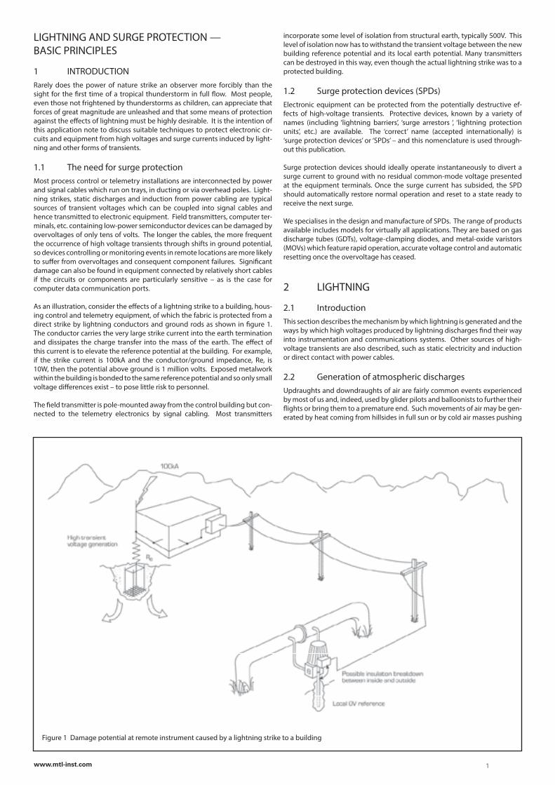
As an illustration, consider the effects of a lightning strike to a building, hous-ing control and telemetry equipment, of which the fabric is protected from a direct strike by lightning conductors and ground rods as shown in figure 1. The conductor carries the very large strike current into the earth termination and dissipates the charge transfer into the mass of the earth. The effect of this current is to elevate the reference potential at the building. For example, if the strike current is 100kA and the conductor/ground impedance, Re, is 10W, then the potential above ground is 1 million volts. Exposed metalwork within the building is bonded to the same reference potential and so only small voltage differences exist – to pose little risk to personnel.
The field transmitter is pole-mounted away from the control building but con-nected to the telemetry electronics by signal cabling. Most transmitters
incorporate some level of isolation from structural earth, typically 500V. This level of isolation now has to withstand the transient voltage between the new building reference potential and its local earth potential. Many transmitters can be destroyed in this way, even though the actual lightning strike was to a protected building.
1.2 Surge protection devices (SPDs)Electronic equipment can be protected from the potentially destructive ef-fects of high-voltage transients. Protective devices, known by a variety of names (including ‘lightning barriers’, ‘surge arrestors ‘, ‘lightning protection units’, etc.) are available. The ‘correct’ name (accepted internationally) is ‘surge protection devices’ or ‘SPDs’ – and this nomenclature is used through-out this publication.
Surge protection devices should ideally operate instantaneously to divert a surge current to ground with no residual common-mode voltage presented at the equipment terminals. Once the surge current has subsided, the SPD should automatically restore normal operation and reset to a state ready to receive the next surge.
We specialises in the design and manufacture of SPDs. The range of products available includes models for virtually all applications. They are based on gas discharge tubes (GDTs), voltage-clamping diodes, and metal-oxide varistors (MOVs) which feature rapid operation, accurate voltage control and automatic resetting once the overvoltage has ceased.
2 LIGHTNING
2.1 IntroductionThis section describes the mechanism by which lightning is generated and the ways by which high voltages produced by lightning discharges find their way into instrumentation and communications systems. Other sources of high-voltage transients are also described, such as static electricity and induction or direct contact with power cables.
2.2 Generation of atmospheric dischargesUpdraughts and downdraughts of air are fairly common events experienced by most of us and, indeed, used by glider pilots and balloonists to further their flights or bring them to a premature end. Such movements of air may be gen-erated by heat coming from hillsides in full sun or by cold air masses pushing
Figure 1 Damage potential at remote instrument caused by a lightning strike to a building
1www.mtl-inst.com
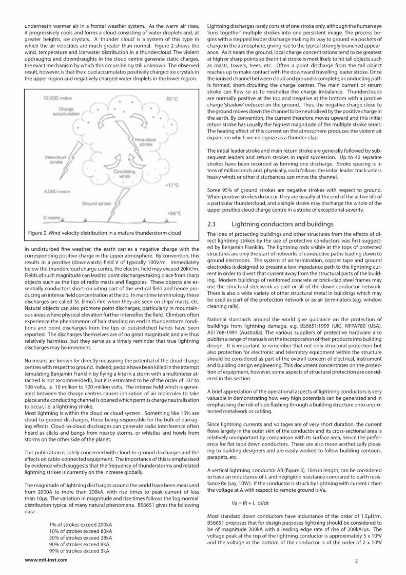
underneath warmer air in a frontal weather system. As the warm air rises, it progressively cools and forms a cloud consisting of water droplets and, at greater heights, ice crystals. A ‘thunder cloud’ is a system of this type in which the air velocities are much greater than normal. Figure 2 shows the wind, temperature and ice/water distribution in a thundercloud. The violent updraughts and downdraughts in the cloud centre generate static charges, the exact mechanism by which this occurs being still unknown. The observed result, however, is that the cloud accumulates positively charged ice crystals in the upper region and negatively charged water droplets in the lower region.
In undisturbed fine weather, the earth carries a negative charge with the corresponding positive charge in the upper atmosphere. By convention, this results in a positive (downwards) field V of typically 100V/m. Immediately below the thundercloud charge centre, the electric field may exceed 20kV/m. Fields of such magnitude can lead to point discharges taking place from sharp objects such as the tips of radio masts and flagpoles. These objects are es-sentially conductors short-circuiting part of the vertical field and hence pro-ducing an intense field concentration at the tip. In maritime terminology these discharges are called ‘St. Elmo’s Fire’ when they are seen on ships’ masts, etc. Natural objects can also promote point discharges, particularly in mountain-ous areas where physical elevation further intensifies the field. Climbers often experience the phenomenon of hair standing on end in thunderstorm condi-tions and point discharges from the tips of outstretched hands have been reported. The discharges themselves are of no great magnitude and are thus relatively harmless, but they serve as a timely reminder that true lightning discharges may be imminent.
No means are known for directly measuring the potential of the cloud charge centres with respect to ground. Indeed, people have been killed in the attempt (emulating Benjamin Franklin by flying a kite in a storm with a multimeter at-tached is not recommended!), but it is estimated to be of the order of 107 to 108 volts, i.e. 10 million to 100 million volts. The intense field which is gener-ated between the charge centres causes ionisation of air molecules to take place and a conducting channel is opened which permits charge neutralisation to occur, i.e. a lightning stroke.Most lightning is within the cloud or cloud system. Something like 15% are cloud-to-ground discharges, these being responsible for the bulk of damag-ing effects. Cloud-to-cloud discharges can generate radio interference often heard as clicks and bangs from nearby storms, or whistles and howls from storms on the other side of the planet.
This publication is solely concerned with cloud-to-ground discharges and the effects on cable-connected equipment. The importance of this is emphasised by evidence which suggests that the frequency of thunderstorms and related lightning strikes is currently on the increase globally.
The magnitude of lightning discharges around the world have been measured from 2000A to more than 200kA, with rise times to peak current of less than 10µs. The variation in magnitude and rise times follows the ‘log-normal’ distribution typical of many natural phenomena. BS6651 gives the following data:–
1% of strokes exceed 200kA 10% of strokes exceed 80kA 50% of strokes exceed 28kA 90% of strokes exceed 8kA 99% of strokes exceed 3kA
Figure 2 Wind velocity distribution in a mature thunderstorm cloud
Lightning discharges rarely consist of one stroke only, although the human eye ‘runs together’ multiple strokes into one persistent image. The process be-gins with a stepped leader discharge making its way to ground via pockets of charge in the atmosphere, giving rise to the typical strongly branched appear-ance. As it nears the ground, local charge concentrations tend to be greatest at high or sharp points so the initial stroke is most likely to hit tall objects such as masts, towers, trees, etc. Often a point discharge from the tall object reaches up to make contact with the downward travelling leader stroke. Once the ionised channel between cloud and ground is complete, a conducting path is formed, short-circuiting the charge centres. The main current or return stroke can flow so as to neutralise the charge imbalance. Thunderclouds are normally positive at the top and negative at the bottom with a positive charge ‘shadow’ induced on the ground. Thus, the negative charge close to the ground moves down the channel to be neutralised by the positive charge in the earth. By convention, the current therefore moves upward and this initial return stroke has usually the highest magnitude of the multiple stroke series. The heating effect of this current on the atmosphere produces the violent air expansion which we recognize as a thunder-clap.
The initial leader stroke and main return stroke are generally followed by sub-sequent leaders and return strokes in rapid succession. Up to 42 separate strokes have been recorded as forming one discharge. Stroke spacing is in tens of milliseconds and, physically, each follows the initial leader track unless heavy winds or other disturbances can move the channel.
Some 95% of ground strokes are negative strokes with respect to ground. When positive strokes do occur, they are usually at the end of the active life of a particular thundercloud, and a single stroke may discharge the whole of the upper positive cloud charge centre in a stroke of exceptional severity.
2.3 Lightning conductors and buildingsThe idea of protecting buildings and other structures from the effects of di-rect lightning strikes by the use of protective conductors was first suggest-ed by Benjamin Franklin. The lightning rods visible at the tops of protected structures are only the start of networks of conductive paths leading down to ground electrodes. The system of air termination, copper tape and ground electrodes is designed to present a low impedance path to the lightning cur-rent in order to divert that current away from the structural parts of the build-ing. Modern buildings of reinforced concrete or brick-clad steel frames may use the structural steelwork as part or all of the down conductor network. There is also a wide variety of other structural metal in buildings which may be used as part of the protection network or as air terminators (e.g. window cleaning rails).
National standards around the world give guidance on the protection of buildings from lightning damage, e.g. BS6651:1999 (UK), NFPA780 (USA), AS1768-1991 (Australia). The various suppliers of protective hardware also publish a range of manuals on the incorporation of their products into building design. It is important to remember that not only structural protection but also protection for electronic and telemetry equipment within the structure should be considered as part of the overall concern of electrical, instrument and building design engineering. This document concentrates on the protec-tion of equipment, however, some aspects of structural protection are consid-ered in this section.
A brief appreciation of the operational aspects of lightning conductors is very valuable in demonstrating how very high potentials can be generated and in emphasising the risk of side flashing through a building structure onto unpro-tected metalwork or cabling.
Since lightning currents and voltages are of very short duration, the current flows largely in the outer skin of the conductor and its cross-sectional area is relatively unimportant by comparison with its surface area; hence the prefer-ence for flat tape down conductors. These are also more aesthetically pleas-ing to building designers and are easily worked to follow building contours, parapets, etc.
A vertical lightning conductor AB (figure 3), 10m in length, can be considered to have an inductance of L and negligible resistance compared to earth resis-tance Re (say, 10W). If the conductor is struck by lightning with current i then the voltage at A with respect to remote ground is Va.
Va = iR + L di/dt
Most standard down conductors have inductance of the order of 1.5µH/m. BS6651 proposes that for design purposes lightning should be considered to be of magnitude 200kA with a leading edge rate of rise of 200kA/µs. The voltage peak at the top of the lightning conductor is approximately 5 x 10⁶V and the voltage at the bottom of the conductor is of the order of 2 x 10⁶V
2www.mtl-inst.com
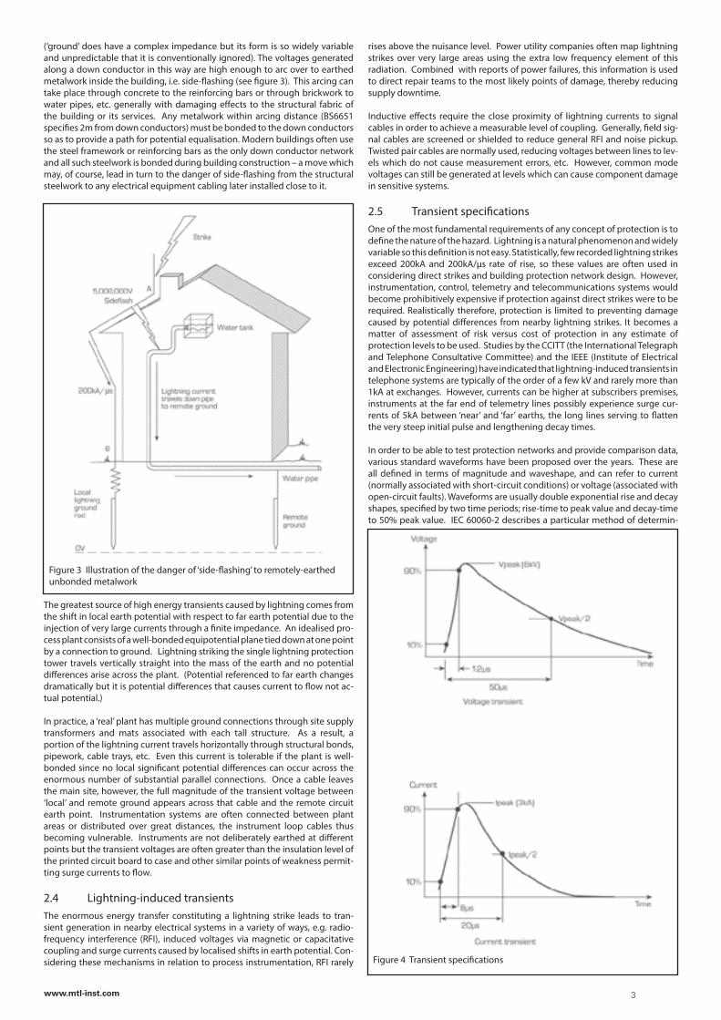
(‘ground’ does have a complex impedance but its form is so widely variable and unpredictable that it is conventionally ignored). The voltages generated along a down conductor in this way are high enough to arc over to earthed metalwork inside the building, i.e. side-flashing (see figure 3). This arcing can take place through concrete to the reinforcing bars or through brickwork to water pipes, etc. generally with damaging effects to the structural fabric of the building or its services. Any metalwork within arcing distance (BS6651 specifies 2m from down conductors) must be bonded to the down conductors so as to provide a path for potential equalisation. Modern buildings often use the steel framework or reinforcing bars as the only down conductor network and all such steelwork is bonded during building construction – a move which may, of course, lead in turn to the danger of side-flashing from the structural steelwork to any electrical equipment cabling later installed close to it.
The greatest source of high energy transients caused by lightning comes from the shift in local earth potential with respect to far earth potential due to the injection of very large currents through a finite impedance. An idealised pro-cess plant consists of a well-bonded equipotential plane tied down at one point by a connection to ground. Lightning striking the single lightning protection tower travels vertically straight into the mass of the earth and no potential differences arise across the plant. (Potential referenced to far earth changes dramatically but it is potential differences that causes current to flow not ac-tual potential.)
In practice, a ‘real’ plant has multiple ground connections through site supply transformers and mats associated with each tall structure. As a result, a portion of the lightning current travels horizontally through structural bonds, pipework, cable trays, etc. Even this current is tolerable if the plant is well-bonded since no local significant potential differences can occur across the enormous number of substantial parallel connections. Once a cable leaves the main site, however, the full magnitude of the transient voltage between ‘local’ and remote ground appears across that cable and the remote circuit earth point. Instrumentation systems are often connected between plant areas or distributed over great distances, the instrument loop cables thus becoming vulnerable. Instruments are not deliberately earthed at different points but the transient voltages are often greater than the insulation level of the printed circuit board to case and other similar points of weakness permit-ting surge currents to flow.
2.4 Lightning-induced transientsThe enormous energy transfer constituting a lightning strike leads to tran-sient generation in nearby electrical systems in a variety of ways, e.g. radio-frequency interference (RFI), induced voltages via magnetic or capacitative coupling and surge currents caused by localised shifts in earth potential. Con-sidering these mechanisms in relation to process instrumentation, RFI rarely
Figure 3 Illustration of the danger of ‘side-flashing’ to remotely-earthed unbonded metalwork
rises above the nuisance level. Power utility companies often map lightning strikes over very large areas using the extra low frequency element of this radiation. Combined with reports of power failures, this information is used to direct repair teams to the most likely points of damage, thereby reducing supply downtime.
Inductive effects require the close proximity of lightning currents to signal cables in order to achieve a measurable level of coupling. Generally, field sig-nal cables are screened or shielded to reduce general RFI and noise pickup. Twisted pair cables are normally used, reducing voltages between lines to lev-els which do not cause measurement errors, etc. However, common mode voltages can still be generated at levels which can cause component damage in sensitive systems.
2.5 Transient specificationsOne of the most fundamental requirements of any concept of protection is to define the nature of the hazard. Lightning is a natural phenomenon and widely variable so this definition is not easy. Statistically, few recorded lightning strikes exceed 200kA and 200kA/µs rate of rise, so these values are often used in considering direct strikes and building protection network design. However, instrumentation, control, telemetry and telecommunications systems would become prohibitively expensive if protection against direct strikes were to be required. Realistically therefore, protection is limited to preventing damage caused by potential differences from nearby lightning strikes. It becomes a matter of assessment of risk versus cost of protection in any estimate of protection levels to be used. Studies by the CCITT (the International Telegraph and Telephone Consultative Committee) and the IEEE (Institute of Electrical and Electronic Engineering) have indicated that lightning-induced transients in telephone systems are typically of the order of a few kV and rarely more than 1kA at exchanges. However, currents can be higher at subscribers premises, instruments at the far end of telemetry lines possibly experience surge cur-rents of 5kA between ‘near’ and ‘far’ earths, the long lines serving to flatten the very steep initial pulse and lengthening decay times.
In order to be able to test protection networks and provide comparison data, various standard waveforms have been proposed over the years. These are all defined in terms of magnitude and waveshape, and can refer to current (normally associated with short-circuit conditions) or voltage (associated with open-circuit faults). Waveforms are usually double exponential rise and decay shapes, specified by two time periods; rise-time to peak value and decay-time to 50% peak value. IEC 60060-2 describes a particular method of determin-
Figure 4 Transient specifications
3www.mtl-inst.com
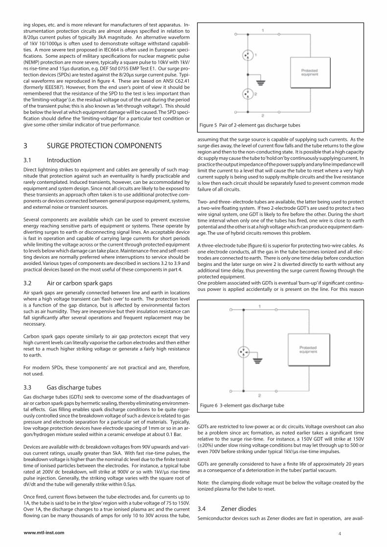
ing slopes, etc. and is more relevant for manufacturers of test apparatus. In-strumentation protection circuits are almost always specified in relation to 8/20µs current pulses of typically 3kA magnitude. An alternative waveform of 1kV 10/1000µs is often used to demonstrate voltage withstand capabili-ties. A more severe test proposed in IEC664 is often used in European speci-fications. Some aspects of military specifications for nuclear magnetic pulse (NEMP) protection are more severe, typically a square pulse to 10kV with 1kV/ns rise-time and 15µs duration, e.g. DEF Std 0755 EMP Test E1. Our surge pro-tection devices (SPDs) are tested against the 8/20µs surge current pulse. Typi-cal waveforms are reproduced in figure 4. These are based on ANSI C62.41 (formerly IEEE587). However, from the end user’s point of view it should be remembered that the resistance of the SPD to the test is less important than the ‘limiting-voltage’ (i.e. the residual voltage out of the unit during the period of the transient pulse; this is also known as ‘let-through voltage’). This should be below the level at which equipment damage will be caused. The SPD speci-fication should define the ‘limiting-voltage’ for a particular test condition or give some other similar indicator of true performance.
3 SURGE PROTECTION COMPONENTS
3.1 IntroductionDirect lightning strikes to equipment and cables are generally of such mag-nitude that protection against such an eventuality is hardly practicable and rarely contemplated. Induced transients, however, can be accommodated by equipment and system design. Since not all circuits are likely to be exposed to these transients an approach often taken is to use additional protective com-ponents or devices connected between general purpose equipment, systems, and external noise or transient sources.
Several components are available which can be used to prevent excessive energy reaching sensitive parts of equipment or systems. These operate by diverting surges to earth or disconnecting signal lines. An acceptable device is fast in operation and capable of carrying large currents for short periods while limiting the voltage across or the current through protected equipment to levels below which damage can take place. Maintenance-free and self-reset-ting devices are normally preferred where interruptions to service should be avoided. Various types of components are described in sections 3.2 to 3.9 and practical devices based on the most useful of these components in part 4.
3.2 Air or carbon spark gapsAir spark gaps are generally connected between line and earth in locations where a high voltage transient can ‘flash over’ to earth. The protection level is a function of the gap distance, but is affected by environmental factors such as air humidity. They are inexpensive but their insulation resistance can fall significantly after several operations and frequent replacement may be necessary.
Carbon spark gaps operate similarly to air gap protectors except that very high current levels can literally vaporise the carbon electrodes and then either reset to a much higher striking voltage or generate a fairly high resistance to earth.
For modern SPDs, these ‘components’ are not practical and are, therefore, not used.
3.3 Gas discharge tubesGas discharge tubes (GDTs) seek to overcome some of the disadvantages of air or carbon spark gaps by hermetic sealing, thereby eliminating environmen-tal effects. Gas filling enables spark discharge conditions to be quite rigor-ously controlled since the breakdown voltage of such a device is related to gas pressure and electrode separation for a particular set of materials. Typically, low voltage protection devices have electrode spacing of 1mm or so in an ar-gon/hydrogen mixture sealed within a ceramic envelope at about 0.1 Bar.
Devices are available with dc breakdown voltages from 90V upwards and vari-ous current ratings, usually greater than 5kA. With fast rise-time pulses, the breakdown voltage is higher than the nominal dc level due to the finite transit time of ionised particles between the electrodes. For instance, a typical tube rated at 200V dc breakdown, will strike at 900V or so with 1kV/µs rise-time pulse injection. Generally, the striking voltage varies with the square root of dV/dt and the tube will generally strike within 0.5µs.
Once fired, current flows between the tube electrodes and, for currents up to 1A, the tube is said to be in the ‘glow’ region with a tube voltage of 75 to 150V. Over 1A, the discharge changes to a true ionised plasma arc and the current flowing can be many thousands of amps for only 10 to 30V across the tube,
assuming that the surge source is capable of supplying such currents. As the surge dies away, the level of current flow falls and the tube returns to the glow region and then to the non-conducting state. It is possible that a high capacity dc supply may cause the tube to ‘hold on’ by continuously supplying current, In practice the output impedance of the power supply and any line impedance will limit the current to a level that will cause the tube to reset where a very high current supply is being used to supply multiple circuits and the live resistance is low then each circuit should be separately fused to prevent common mode failure of all circuits.
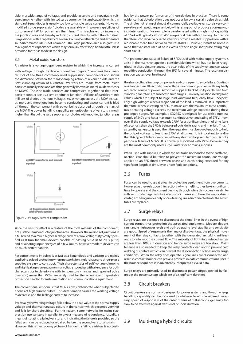
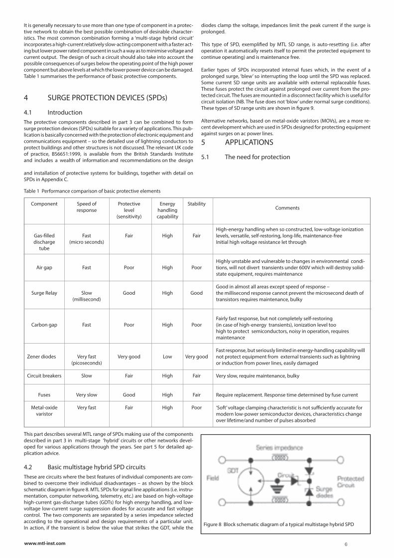
Two- and three- electrode tubes are available, the latter being used to protect a two-wire floating system. If two 2-electrode GDT’s are used to protect a two wire signal system, one GDT is likely to fire before the other. During the short time interval when only one of the tubes has fired, one wire is close to earth potential and the other is at a high voltage which can produce equipment dam-age. The use of hybrid circuits removes this problem.
A three-electrode tube (figure 6) is superior for protecting two-wire cables. As one electrode conducts, all the gas in the tube becomes ionized and all elec-trodes are connected to earth. There is only one time delay before conduction begins and the later surge on wire 2 is diverted directly to earth without any additional time delay, thus preventing the surge current flowing through the protected equipment.One problem associated with GDTs is eventual ‘burn-up’ if significant continu-ous power is applied accidentally or is present on the line. For this reason
GDTs are restricted to low-power ac or dc circuits. Voltage overshoot can also be a problem since arc formation, as noted earlier takes a significant time relative to the surge rise-time. For instance, a 150V GDT will strike at 150V (±20%) under slow rising voltage conditions but may let through up to 500 or even 700V before striking under typical 1kV/µs rise-time impulses.
GDTs are generally considered to have a finite life of approximately 20 years as a consequence of a deterioration in the tubes’ partial vacuum.
Note: the clamping diode voltage must be below the voltage created by the ionized plasma for the tube to reset.
3.4 Zener diodesSemiconductor devices such as Zener diodes are fast in operation, are avail-
Figure 5 Pair of 2-element gas discharge tubes
Figure 6 3-element gas discharge tube
4www.mtl-inst.com
able in a wide range of voltages and provide accurate and repeatable volt-age clamping – albeit with limited surge current withstand capability which, in standard Zener diodes is usually too low to handle surge currents. However, modified ‘surge suppression’ diodes are available with power capabilities of up to several kW for pulses less than 1ms. This is achieved by increasing the junction area and thereby reducing current density within the chip itself. Surge diodes with a capability of several kW can be rather large and expensive so indiscriminate use is not common. The large junction area also gives rise to a significant capacitance which may seriously affect loop bandwidth unless provision for this is made in the design.
3.5 Metal oxide varistorsA varistor is a voltage-dependent resistor in which the increase in current
with voltage through the device is non-linear. Figure 7 compares the charac-teristics of the three commonly used suppression components and shows the difference between the ‘hard’ clamping action of a Zener diode and the ‘soft’ clamping action of a varistor. Varistors are made from metal oxide particles (usually zinc) and are thus generally known as ‘metal-oxide varistors’ or ‘MOVs’. The zinc oxide particles are compressed together so that inter-particle contact acts as a semiconductor junction. Millions of particles mimic millions of diodes at various voltages, so, as voltage across the MOV increas-es, more and more junctions become conducting and excess current is bled off through the component with power being absorbed through the mass of the MOV. The power handling capability per unit-volume of varistors is much higher than that of the surge suppression diodes with modified junction areas
since the varistor effect is a feature of the total material of the component, not just the semiconductor junction area. However, the millions of junctions in a MOV lead to a much higher leakage current at low voltages (typically speci-fied as 0.1mA for small devices capable of passing 500A [8 to 20µs pulse] and dissipating input energies of a few Joules, however modern devices can be much better than this.
Response time to impulses is as fast as a Zener diode and varistors are mainly applied to ac load protection where networks for single-phase and three-phase supplies are easy to construct. Their characteristics of ‘soft’ voltage clamping and high leakage current at nominal voltage (together with a tendency for both characteristics to deteriorate with temperature changes and repeated pulse diversion) mean that MOVs are rarely used for the accurate and repeatable protection needed for instrumentation and communications equipment.
The conventional wisdom is that MOVs slowly deteriorate when subjected to a series of high current pulses. This deterioration causes the working voltage to decrease and the leakage current to increase.
Eventually the working voltage falls below the peak value of the normal supply voltage and thermal runaway occurs in the varistor which becomes very hot and fails by short circuiting. For this reason, some networks for mains sup-pression use varistors in parallel to give a measure of redundancy. Usually, a means of isolating a failed varistor and indicating the failure is provided so the failed unit can be replaced or repaired before the second varistor also fails.However, this rather gloomy picture of frequently failing varistors is not justi-
Figure 7 Voltage/current comparisons
fied by the power performance of these devices in practice. There is some evidence that deterioration does not occur below a certain pulse threshold. The single shot rating of almost all commercially available varistors is very con-servative and repetitive pulses below this rating do not produce a correspond-ing deterioration. For example, a varistor rated with a single shot capability of 6.5kA will typically absorb 400 surges of 4.3kA without failing. In practice therefore, conservatively rated varistors provide reliable suppression with a reasonable mean time between failures (MTBF). However, it must be borne in mind that varistors used at or in excess of their single shot pulse rating may short circuit.
The predominant cause of failure of SPDs used with mains supply systems is a rise in the mains voltage for a considerable time which has not been recog-nized. In these circumstances, the peak value of the supply voltage can cause repetitive conduction through the SPD for several minutes. The resulting dis-sipation causes over heating of
the shunt voltage limiting components and consequent device failure. Continu-ous (longer than 10 seconds) overvoltage is a common problem with any badly regulated source of power. Almost all supplies backed up by or derived from standby generators are subject to such surges. Similarly, locations fed by long cables which are subject to large load variations frequently have unexpect-edly high voltages when a major part of the load is removed. It is important therefore, when selecting an SPD, to make sure the maximum rated continu-ous operating voltage exceeds the maximum voltage expected during these prolonged surges. For example, a SD275X is designed for use with a nominal supply of 240V and has a maximum continuous voltage rating of 275V; how-ever, if the supply voltage exceeds 275V for a significant length of time (tens of seconds), then the SPD is being used outside its rating and may fail. Thus, if a standby generator is used then the regulator must be good enough to hold the output voltage to less than 275V at all times. It is important to realise that this type of failure can occur with any shunt voltage regulator and is not a particular failure of MOVs. It is normally associated with MOVs because they are the most commonly used surge limiters for ac mains supplies.
When used with supplies in which the neutral is not bonded to the earth con-nection, care should be taken to prevent the maximum continuous voltage applied to an SPD fitted between phase and earth being exceeded for any significant length of time, even under fault conditions.
3.6 Fuses
Fuses can be used to great effect in protecting equipment from overcurrents. However, as they rely upon thin sections of wire melting, they take a significant time to operate and the current passing through while this occurs can still be sufficient to damage sensitive electronics. Fuses also have the major disad-vantage of being usable only once – leaving lines disconnected until the blown fuses are replaced.
3.7 Surge relays
Surge relays are designed to disconnect the signal lines in the event of high current surges, thus protecting the associated equipment. Modern designs can handle high power levels and both operating level stability and sensitivity are good. Speed of response is their major disadvantage, the physical move-ment of the relay contacts together with the generated arc taking millisec-onds to interrupt the current flow. The majority of lightning induced surges are less than 100µs in duration and hence surge relays are too slow. Main-tenance is also needed to keep the relay contacts clean and to prevent cold welding of contacts which can prevent the disconnection of lines under surge conditions. When the relay does operate, signal lines are disconnected and reset so contact bounce can prove a problem in data communications lines if the bounce sequence is inadvertently interpreted as valid data.
Surge relays are primarily used to disconnect power surges created by fail-ures in the power system which are of a significant duration.
3.8 Circuit breakers
Circuit breakers are normally designed for power systems and though energy handling capability can be increased to whatever level is considered neces-sary, speed of response is of the order of tens of milliseconds, generally too slow to be effective against transients of short duration.
3.9 Multi-stage hybrid circuits
5www.mtl-inst.com
It is generally necessary to use more than one type of component in a protec-tive network to obtain the best possible combination of desirable character-istics. The most common combination forming a ‘multi-stage hybrid circuit’ incorporates a high-current relatively slow-acting component with a faster act-ing but lower power rated component in such a way as to minimise voltage and current output. The design of such a circuit should also take into account the possible consequences of surges below the operating point of the high power component but above levels at which the lower power device can be damaged. Table 1 summarises the performance of basic protective components.
4 SURGE PROTECTION DEVICES (SPDs)
4.1 IntroductionThe protective components described in part 3 can be combined to form surge protection devices (SPDs) suitable for a variety of applications. This pub-lication is basically concerned with the protection of electronic equipment and communications equipment – so the detailed use of lightning conductors to protect buildings and other structures is not discussed. The relevant UK code of practice, BS6651:1999, is available from the British Standards Institute and includes a wealth of information and recommendations on the design
and installation of protective systems for buildings, together with detail on SPDs in Appendix C.
This part describes several MTL range of SPDs making use of the components described in part 3 in multi-stage ‘hybrid’ circuits or other networks devel-oped for various applications through the years. See part 5 for detailed ap-plication advice.
4.2 Basic multistage hybrid SPD circuitsThese are circuits where the best features of individual components are com-bined to overcome their individual disadvantages – as shown by the block schematic diagram in figure 8. MTL SPDs for signal line applications (i.e. instru-mentation, computer networking, telemetry, etc.) are based on high-voltage high-current gas-discharge tubes (GDTs) for high energy handling, and low-voltage low-current surge suppression diodes for accurate and fast voltage control. The two components are separated by a series impedance selected according to the operational and design requirements of a particular unit. In action, if the transient is below the value that strikes the GDT, while the
diodes clamp the voltage, impedances limit the peak current if the surge is prolonged.
This type of SPD, exemplified by MTL SD range, is auto-resetting (i.e. after operation it automatically resets itself to permit the protected equipment to continue operating) and is maintenance free.
Earlier types of SPDs incorporated internal fuses which, in the event of a prolonged surge, ‘blew’ so interrupting the loop until the SPD was replaced. Some current SD range units are available with external replaceable fuses. These fuses protect the circuit against prolonged over current from the pro-tected circuit. The fuses are mounted in a disconnect facility which is useful for circuit isolation (NB. The fuse does not ‘blow’ under normal surge conditions). These types of SD range units are shown in figure 9.
Alternative networks, based on metal-oxide varistors (MOVs), are a more re-cent development which are used in SPDs designed for protecting equipment against surges on ac power lines.
5 APPLICATIONS
5.1 The need for protection
Table 1 Performance comparison of basic protective elements
Component Speed of Protective Energy Stability response level handling (sensitivity) capability
Gas-filled Fast Fair High Fair discharge (micro seconds) tube
Air gap Fast Poor High Poor
Surge Relay Slow Good High Good (millisecond)
Carbon gap Fast Poor High Poor
Zener diodes Very fast Very good Low Very good (picoseconds)
Circuit breakers Slow Fair High Fair
Fuses Very slow Good High Fair
Metal-oxide Very fast Fair High Poor varistor
High-energy handling when so constructed, low-voltage ionization levels, versatile, self-restoring, long-life, maintenance-freeInitial high voltage resistance let through
Highly unstable and vulnerable to changes in environmental condi-tions, will not divert transients under 600V which will destroy solid-state equipment, requires maintenance
Good in almost all areas except speed of response – the millisecond response cannot prevent the microsecond death of transistors requires maintenance, bulky
Fairly fast response, but not completely self-restoring(in case of high-energy transients), ionization level toohigh to protect semiconductors, noisy in operation, requires maintenance
Fast response, but seriously limited in energy-handling capability will not protect equipment from external transients such as lightning or induction from power lines, easily damaged
Very slow, require maintenance, bulky
Require replacement. Response time determined by fuse current
‘Soft’ voltage clamping characteristic is not sufficiently accurate for modern low-power semiconductor devices, characteristics change over lifetime/and number of pulses absorbed
Figure 8 Block schematic diagram of a typical multistage hybrid SPD
6www.mtl-inst.com
Comments
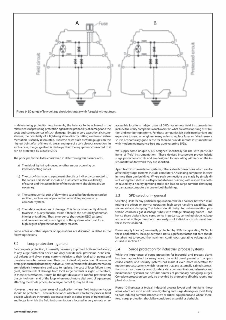
Figure 9 SD range of low-voltage circuit designs; a) with fuses; b) without fuses
A B
In determining protection requirements, the balance to be achieved is the relative cost of providing protection against the probability of damage and the costs and consequences of such damage. Except in very exceptional circum-stances, the possibility of a lightning strike directly hitting electronic instru-mentation is usually discounted. Extreme cases such as wind gauges on the highest point of an offshore rig are an example of a conspicuous exception. In such a case, the gauge itself is destroyed but the equipment connected to it can be protected by suitable SPDs.
The principal factors to be considered in determining this balance are:–
a) The risk of lightning-induced or other surges occurring on interconnecting cables.
b) The cost of damage to equipment directly or indirectly connected to the cables. This should include an assessment of the availability of spares and the accessibility of the equipment should repairs be necessary.
c) The consequential cost of downtime caused before damage can be rectified, such as loss of production or work in progress on a computer system.
d) The safety implications of damage. This factor is frequently difficult to assess in purely financial terms if there is the possibility of human injuries or fatalities. Thus, emergency shut-down (ESD) systems and fire alarm monitors are typical of the systems which call for a high degree of protection for safety reasons.
Some notes on other aspects of applications are discussed in detail in the following sections.
5.2 Loop protection – generalFor complete protection, it is usually necessary to protect both ends of a loop, as any surge protection device can only provide local protection. SPDs con-trol voltage and divert surge currents relative to their local earth points and therefore ‘remote’ devices need their own individual protection. However, in average industrial plants many individual items of remote field instrumentation are relatively inexpensive and easy to replace, the cost of loop failure is not great, and the risk of damage from local surge currents is slight – therefore, in these circumstances, it may be thought desirable to confine protection to the control room end of the loop where much more vital control equipment affecting the whole process (or a major part of it) may be at risk.
However, there are some areas of application where field instrumentation should be protected. These include loops which are vital to the process, field devices which are inherently expensive (such as some types of transmitters), and loops in which the field instrumentation is located in very remote or in-
accessible locations. Major users of SPDs for remote field instrumentation include the utility companies which maintain what are often far-flung distribu-tion and monitoring systems. For these companies it is both inconvenient and expensive to send an engineer many miles to replace fuses or failed sensors, so it is economically good sense for them to provide remote instrumentation with modern maintenance-free and auto-resetting SPDs.
We supply some unique SPDs designed specifically for use with particular items of ‘field’ instrumentation. These devices incorporate proven hybrid surge protection circuits and are designed for mounting within or on the in-strumentation for which they are specified.
Apart from instrumentation systems, other cabled connections which can be affected by surge currents include computer LANs linking computers located in more than one building. Where such connections are made by simple di-rect wiring then shifts in earth potential of one building with respect to anoth-er caused by a nearby lightning strike can lead to surge currents destroying or damaging computers in one or both buildings.
5.3 SPD selection – generalSelecting SPDs for any particular application calls for a balance between mini-mising the effects on normal operation, high surge handling capability, and secure voltage clamping. The hybrid circuit design for instrumentation pro-tection combines gas discharge tubes with voltage clamping diodes – and hence these designs have some series impedance, controlled diode leakage and a small voltage overshoot. An analysis of individual circuits must bear these factors in mind.
Power supply lines (ac) are usually protected by SPDs incorporating MOVs. In these applications, leakage current is not a significant factor but care should be taken not to exceed the maximum continuous operating voltage as dis-cussed in section 3.5.
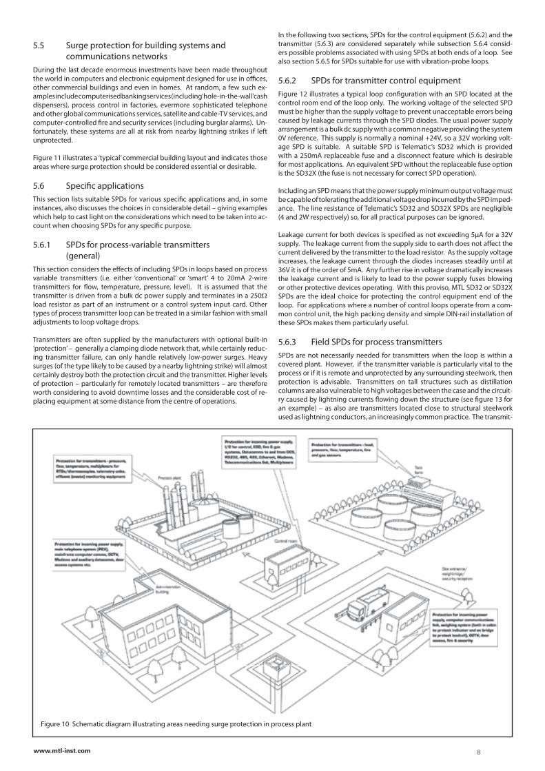
5.4 Surge protection for industrial process systemsWhile the importance of surge protection for industrial and process plants has been appreciated for many years, the rapid development of comput-erised control and security systems has made it even more imperative for modern process systems which recognise that any externally-cabled connec-tions (such as those for control, safety, data communications, telemetry and maintenance systems) are possible sources of potentially damaging surges. Complete protection can only be provided by protecting all cable routes into plant structures.
Figure 10 illustrates a ‘typical’ industrial process layout and highlights those areas which are most at risk from lightning and surge damage or most likely to pass induced currents into sensitive or critical equipment and where, there-fore, surge protection should be considered essential or desirable.
7www.mtl-inst.com
5.5 Surge protection for building systems and communications networksDuring the last decade enormous investments have been made throughout the world in computers and electronic equipment designed for use in offices, other commercial buildings and even in homes. At random, a few such ex-amples include computerised banking services (including ‘hole-in-the-wall’ cash dispensers), process control in factories, evermore sophisticated telephone and other global communications services, satellite and cable-TV services, and computer-controlled fire and security services (including burglar alarms). Un-fortunately, these systems are all at risk from nearby lightning strikes if left unprotected.
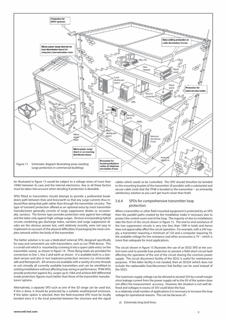
Figure 11 illustrates a ‘typical’ commercial building layout and indicates those areas where surge protection should be considered essential or desirable.
5.6 Specific applicationsThis section lists suitable SPDs for various specific applications and, in some instances, also discusses the choices in considerable detail – giving examples which help to cast light on the considerations which need to be taken into ac-count when choosing SPDs for any specific purpose.
5.6.1 SPDs for process-variable transmitters (general) This section considers the effects of including SPDs in loops based on process variable transmitters (i.e. either ‘conventional’ or ‘smart’ 4 to 20mA 2-wire transmitters for flow, temperature, pressure, level). It is assumed that the transmitter is driven from a bulk dc power supply and terminates in a 250W load resistor as part of an instrument or a control system input card. Other types of process transmitter loop can be treated in a similar fashion with small adjustments to loop voltage drops.
Transmitters are often supplied by the manufacturers with optional built-in ‘protection’ – generally a clamping diode network that, while certainly reduc-ing transmitter failure, can only handle relatively low-power surges. Heavy surges (of the type likely to be caused by a nearby lightning strike) will almost certainly destroy both the protection circuit and the transmitter. Higher levels of protection – particularly for remotely located transmitters – are therefore worth considering to avoid downtime losses and the considerable cost of re-placing equipment at some distance from the centre of operations.
In the following two sections, SPDs for the control equipment (5.6.2) and the transmitter (5.6.3) are considered separately while subsection 5.6.4 consid-ers possible problems associated with using SPDs at both ends of a loop. See also section 5.6.5 for SPDs suitable for use with vibration-probe loops.
5.6.2 SPDs for transmitter control equipment Figure 12 illustrates a typical loop configuration with an SPD located at the control room end of the loop only. The working voltage of the selected SPD must be higher than the supply voltage to prevent unacceptable errors being caused by leakage currents through the SPD diodes. The usual power supply arrangement is a bulk dc supply with a common negative providing the system 0V reference. This supply is normally a nominal +24V, so a 32V working volt-age SPD is suitable. A suitable SPD is Telematic’s SD32 which is provided with a 250mA replaceable fuse and a disconnect feature which is desirable for most applications. An equivalent SPD without the replaceable fuse option is the SD32X (the fuse is not necessary for correct SPD operation).
Including an SPD means that the power supply minimum output voltage must be capable of tolerating the additional voltage drop incurred by the SPD imped-ance. The line resistance of Telematic’s SD32 and SD32X SPDs are negligible (4 and 2W respectively) so, for all practical purposes can be ignored.
Leakage current for both devices is specified as not exceeding 5µA for a 32V supply. The leakage current from the supply side to earth does not affect the current delivered by the transmitter to the load resistor. As the supply voltage increases, the leakage current through the diodes increases steadily until at 36V it is of the order of 5mA. Any further rise in voltage dramatically increases the leakage current and is likely to lead to the power supply fuses blowing or other protective devices operating. With this proviso, MTL SD32 or SD32X SPDs are the ideal choice for protecting the control equipment end of the loop. For applications where a number of control loops operate from a com-mon control unit, the high packing density and simple DIN-rail installation of these SPDs makes them particularly useful.
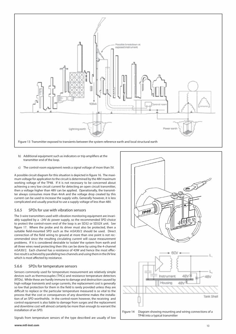
5.6.3 Field SPDs for process transmittersSPDs are not necessarily needed for transmitters when the loop is within a covered plant. However, if the transmitter variable is particularly vital to the process or if it is remote and unprotected by any surrounding steelwork, then protection is advisable. Transmitters on tall structures such as distillation columns are also vulnerable to high voltages between the case and the circuit-ry caused by lightning currents flowing down the structure (see figure 13 for an example) – as also are transmitters located close to structural steelwork used as lightning conductors, an increasingly common practice. The transmit-
Figure 10 Schematic diagram illustrating areas needing surge protection in process plant
8www.mtl-inst.com
ter illustrated in figure 13 would be subject to a voltage stress of more than 100kV between its case and the internal electronics. Any or all these factors must be taken into account when deciding if protection is desirable.
SPDs fitted to transmitters should attempt to provide a preferential break-down path between lines and lines/earth so that any surge currents thus in-duced flow along that path rather than through the transmitter circuitry. The type of transient protection offered as an optional extra by most transmitter manufacturers generally consists of surge suppression diodes or, occasion-ally, varistors. The former type provides protection only against low-voltage and the latter only against high-voltage surges. Devices incorporating hybrid circuits combining gas discharge tubes, varistors and surge suppression di-odes are the obvious answer but, until relatively recently, were not easy to implement on account of the physical difficulties of packaging the more com-plex network within the body of the transmitter.
The better solution is to use a ‘dedicated’ external SPD, designed specifically for easy and convenient use with transmitters, such as our TP48 device. This is a small unit which is mounted by screwing it into a spare ‘cable entry’ on the transmitter casing as shown in figure 14. Three flying leads are provided for connection to line 1, line 2 and earth as shown. It is available both in a stan-dard version and also in two ‘explosion-protection’ versions (i.e. intrinsically-safe and flameproof). All versions are available with a variety of screw-threads to suit virtually all currently available transmitters and can be retrofitted to existing installations without affecting loop wiring or performance. TP48 SPDs provide protection against ALL surges up to 10kA and achieve 60V differential mode protection, figures much better than those of the transmitter manufac-turers’ options.
Alternatively, a separate SPD such as one of the SD range can be used but, if this is done, it should be protected by a suitable weatherproof enclosure. If this latter option is selected, then the field-mounted SPD must be locally bonded since it is the local potential between the structure and the signal
Figure 11 Schematic diagram illustrating areas needing surge protection in commercial buildings
cables which needs to be controlled. The SPD should therefore be bonded to the mounting bracket of the transmitter (if possible) with a substantial and secure cable (note that the TP48 is bonded to the transmitter – an eminently satisfactory solution as you can’t get much closer than that!)
5.6.4 SPDs for comprehensive transmitter loop protection When a transmitter or other field-mounted equipment is protected by an SPD then the parallel paths created by the installation make it necessary also to protect the control-room end of the loop. The majority of also to installations take the form of the circuit shown in figure 15. The end-to-end resistance of the two suppression circuits is very low (less than 10W in total) and hence does not appreciably affect the circuit operation. For example, with a 24V sup-ply, a transmitter requiring a minimum of 12V and a computer requiring 5V, the available voltage for line resistance and other accessories is 7V – which is more than adequate for most applications.
The circuit shown in figure 15 illustrates the use of an SD32 SPD at the con-trol-room end to provide fuse protection to prevent a field short-circuit fault affecting the operation of the rest of the circuit sharing the common power supply. The circuit disconnect facility of the SD32 is useful for maintenance purposes. If this latter facility is not needed, then an SD32X (which does not include the replaceable fuse/disconnect link facility) can be used instead of the SD32.
The maximum supply voltage can be allowed to exceed 32V by a small margin since leakage current from the power supply rail to the 0V of the system does not affect the measurement accuracy. However, the situation is not well de-fined and voltages in excess of 35V could blow the fuse.In a relatively small number of applications it is necessary to increase the loop voltage for operational reasons. This can be because of:–
a) Extremely long land lines.
9www.mtl-inst.com
b) Additional equipment such as indicators or trip amplifiers at the transmitter end of the loop.
c) The control-room equipment needs a signal voltage of more than 5V.
A possible circuit diagram for this situation is depicted in figure 16. The maxi-mum voltage for application to the circuit is determined by the 48V maximum working voltage of the TP48. If it is not necessary to be concerned about achieving a very low circuit current for detecting an open circuit transmitter, then a voltage higher than 48V can be applied. Operationally, the transmit-ter always consumes more than 4mA and the voltage drop created by this current can be used to increase the supply volts. Generally however, it is less complicated and usually practical to use a supply voltage of less than 48V.
5.6.5 SPDs for use with vibration sensorsThe 3-wire transmitters used with vibration monitoring equipment are invari-ably supplied by a –24V dc power supply, so the recommended SPD choice to protect the control-room end of the loop is an SD32 or SD32X unit. See figure 17. Where the probe and its driver must also be protected, then a suitable field-mounted SPD such as the mSA30/2 should be used. Direct connection of the field wiring to ground at more than one point is not rec-ommended since the resulting circulating current will cause measurement problems. If it is considered desirable to ‘isolate’ the system from earth and all three wires need protecting then this can be done by using the 4-channel mSA30/2. Each channel has a resistance of 43W and hence the most effec-tive result is achieved by paralleling two channels and using them in the 0V line which is most affected by resistance.
5.6.6 SPDs for temperature sensorsSensors commonly used for temperature measurement are relatively simple devices such as thermocouples (THCs) and resistance temperature detectors (RTDs). While these are hardly immune to damage and destruction caused by high-voltage transients and surge currents, the replacement cost is generally so low that protection for them in the field is rarely provided unless they are difficult to replace or the particular temperature measured is so vital to the process that the cost or consequences of any downtime makes the installa-tion of an SPD worthwhile. In the control-room however, the receiving and control equipment is also liable to damage from surges and the replacement and downtime cost will almost certainly be more than enough to warrant the installation of an SPD.
Signals from temperature sensors of the type described are usually of low
Figure 13 Transmitter exposed to transients between the system reference earth and local structural earth
Figure 14 Diagram showing mounting and wiring connections of a TP48 into a typical transmitter
10www.mtl-inst.com
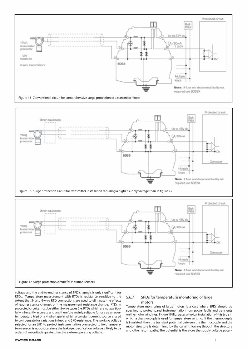
Figure 15 Conventional circuit for comprehensive surge protection of a transmitter loop
Figure 16 Surge protection circuit for transmitter installation requiring a higher supply voltage than in figure 15
Figure 17 Surge protection circuit for vibration sensors
voltage and the end-to-end resistance of SPD channels is only significant for RTDs. Temperature measurement with RTDs is resistance sensitive to the extent that 3- and 4-wire RTD connections are used to eliminate the effects of lead resistance changes on the measurement resistance change. RTDs in protected circuits must be either 2-wire types (i.e. RTDs which are not particu-larly inherently accurate and are therefore mainly suitable for use as an over-temperature trip) or a 4-wire type in which a constant-current source is used to compensate for variations in lead and SPD resistance. The working voltage selected for an SPD to protect instrumentation connected to field tempera-ture sensors is not critical since the leakage specification voltage is likely to be orders of magnitude greater than the system operating voltage.
5.6.7 SPDs for temperature monitoring of large motorsTemperature monitoring of large motors is a case where SPDs should be specified to protect panel instrumentation from power faults and transients on the motor windings. Figure 18 illustrates a typical installation of this type in which a thermocouple is used for temperature sensing. If the thermocouple is insulated, then the transient potential between the thermocouple and the motor structure is determined by the current flowing through the structure and other return paths. The potential is therefore the supply voltage poten-
11www.mtl-inst.com
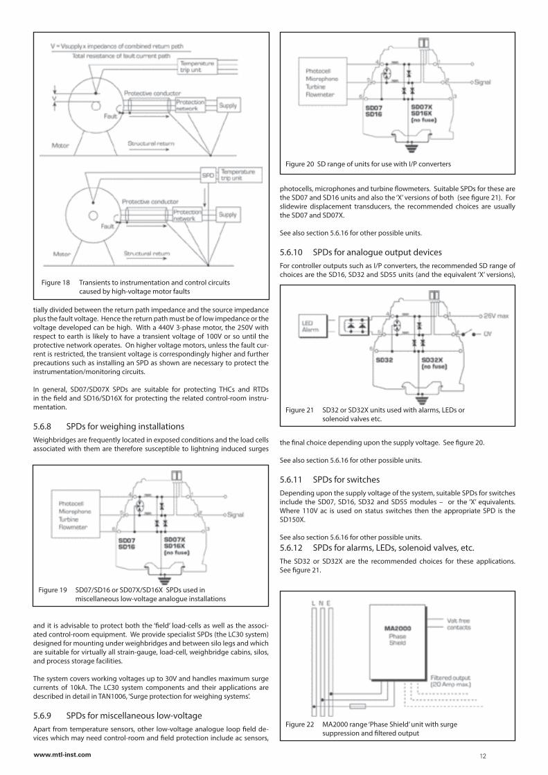
Figure 22 MA2000 range ‘Phase Shield’ unit with surge suppression and filtered output
tially divided between the return path impedance and the source impedance plus the fault voltage. Hence the return path must be of low impedance or the voltage developed can be high. With a 440V 3-phase motor, the 250V with respect to earth is likely to have a transient voltage of 100V or so until the protective network operates. On higher voltage motors, unless the fault cur-rent is restricted, the transient voltage is correspondingly higher and further precautions such as installing an SPD as shown are necessary to protect the instrumentation/monitoring circuits.
In general, SD07/SD07X SPDs are suitable for protecting THCs and RTDs in the field and SD16/SD16X for protecting the related control-room instru-mentation.
5.6.8 SPDs for weighing installationsWeighbridges are frequently located in exposed conditions and the load cells associated with them are therefore susceptible to lightning induced surges
and it is advisable to protect both the ‘field’ load-cells as well as the associ-ated control-room equipment. We provide specialist SPDs (the LC30 system) designed for mounting under weighbridges and between silo legs and which are suitable for virtually all strain-gauge, load-cell, weighbridge cabins, silos, and process storage facilities.
The system covers working voltages up to 30V and handles maximum surge currents of 10kA. The LC30 system components and their applications are described in detail in TAN1006, ‘Surge protection for weighing systems’.
5.6.9 SPDs for miscellaneous low-voltage
Apart from temperature sensors, other low-voltage analogue loop field de-vices which may need control-room and field protection include ac sensors,
Figure 18 Transients to instrumentation and control circuits caused by high-voltage motor faults
Figure 19 SD07/SD16 or SD07X/SD16X SPDs used in miscellaneous low-voltage analogue installations
Figure 20 SD range of units for use with I/P converters
photocells, microphones and turbine flowmeters. Suitable SPDs for these are the SD07 and SD16 units and also the ‘X’ versions of both (see figure 21). For slidewire displacement transducers, the recommended choices are usually the SD07 and SD07X.
See also section 5.6.16 for other possible units.
5.6.10 SPDs for analogue output devicesFor controller outputs such as I/P converters, the recommended SD range of choices are the SD16, SD32 and SD55 units (and the equivalent ‘X’ versions),
the final choice depending upon the supply voltage. See figure 20.
See also section 5.6.16 for other possible units.
5.6.11 SPDs for switchesDepending upon the supply voltage of the system, suitable SPDs for switches include the SD07, SD16, SD32 and SD55 modules – or the ‘X’ equivalents. Where 110V ac is used on status switches then the appropriate SPD is the SD150X.
See also section 5.6.16 for other possible units.5.6.12 SPDs for alarms, LEDs, solenoid valves, etc. The SD32 or SD32X are the recommended choices for these applications. See figure 21.
Figure 21 SD32 or SD32X units used with alarms, LEDs or solenoid valves etc.
12www.mtl-inst.com
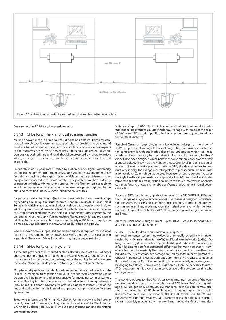
Figure 23 Network surge protectors at both ends of a cable linking computers
See also section 5.6.16 for other possible units.
5.6.13 SPDs for primary and local ac mains suppliesMains ac power lines are prime sources of noise and external transients con-ducted into electronic systems. Aware of this, we provide a wide range of products based on metal-oxide varistor circuits to address various aspects of the problems posed by ac power lines and cables. Ideally, ALL distribu-tion boards, both primary and local, should be protected by suitable devices which, in every case, should be mounted either on the board or as close to it as possible.
Frequently mains supplies are distorted by high frequency signals which may be fed into equipment from the mains supply. Alternatively, equipment may feed signals back into the supply system which can cause problems in other equipment connected to the same supply. These problems can be avoided by using a unit which combines surge suppression and filtering. It is desirable to avoid the ringing which occurs when a fast rise time pulse is applied to the filter and these units utilise a special circuit to prevent this.
For primary distribution boards (i.e. those connected directly to the mains sup-ply feeding a building) the usual recommendation is a MA2000 Phase Shield Series unit which is available in single and three phase versions for 110V or 240V supplies. This unit provides a level of protection which is more than ade-quate for almost all situations, and being spur connected is not affected by the current rating of the supply. If a single phase filtered supply is required then in addition to the spur connected suppression facility a 20A filtered supply can be made available by using the MA2001/F as illustrated in figure 22.
Where a lower-power suppressed and filtered supply is required, for example for a rack of instrumentation, then MA05 or MA10 units which are available in a standard filter can or DIN rail mounting may be the better solution.
5.6.14 SPDs for telemetry systemsAs the first providers of distributed cabled networks (much of it out of doors and covering long distances) telephone systems were also one of the first major users of surge protection devices, hence the application of surge pro-tection to telemetry is widely accepted and, generally, well understood.
Many telemetry systems use telephone lines (either private ‘dedicated’ or pub-lic dial-up) for signal transmission and SPDs used for these applications must be approved by national bodies responsible for providing communications service. Bearing in mind the openly distributed nature of many telemetry installations, it is clearly advisable to protect equipment at both ends of the line and we have borne this in mind with product ranges available for these applications.
Telephone systems use fairly high dc voltages for line supply and bell opera-tion. Typical system working voltages are of the order of 40 to 50V dc. In the UK, ringing voltages are 120 to 140V but some systems can impose ringing
voltages of up to 270V. Electronic telecommunications equipment includes ‘subscriber line interface circuits’ which have voltage withstands of the order of 60V or so. SPD’s used in public telephone systems are required to adhere to the R&TTE directive.
Standard Zener or surge diodes with breakdown voltages of the order of 180V can provide clamping of transient surges but the power dissipation in the component is high and leads either to an unacceptably high cost or to a reduced life expectancy for the network. To solve this problem, ‘foldback’ diodes have been designed which behave as conventional Zener diodes below a critical voltage known as the ‘voltage breakdown level’ or VBR, i.e. a small amount of reverse leakage current. Above VBR, the device begins to con-duct very rapidly, the changeover taking place in picoseconds (10-12s). With a conventional Zener diode, as voltage increases across it, current increases through it with a slope resistance of typically 1 or 2W. With foldback diodes however, the voltage across the unit collapses to a much lower value when the current is flowing through it, thereby significantly reducing the internal power dissipation.
Specialist SPDs for telemetry applications include the DP200 BT & RJ SPDs and the TS range of surge protection devices. The former is designed for installa-tion between line jacks and telephone socket outlets to protect equipment such as fax machines, modems, extension telephones etc. while the latter units are designed to protect local PABX exchanges against surges on incom-ing lines.
All these units handle surge currents up to 10kA. See also sections 5.6.15 and 5.6.16 for other related units.
5.6.15 SPDs for data communications equipmentIn-house computer systems nowadays are generally extensively intercon-nected by ‘wide area networks’ (WANs) and ‘local area networks’ (LANs). So long as such a system is confined to one building, it is difficult to conceive of a fault leading to significant potential differences between computers. How-ever, when, as is increasingly the case, the network extends to more than one building, the risk of computer damage caused by shifts in earth potential is obviously increased. SPDs at both ends are normally the wisest solution as illustrated by figure 23. If the connection is between totally separate systems belonging to different companies or institutions, then the necessity to insert SPDs between them is even greater so as to avoid disputes concerning who damaged what.
The working voltage for the SPD relates to the maximum voltage of the com-munications ‘driver’ cards which rarely exceed 12V, hence 16V working volt-age SPDs are generally adequate. EIA standards exist for data communica-tions and the number of SPD channels necessary depends upon the particular implementation in use. For instance, the RS232C format specifies 25 lines between two computer systems. Most systems use 3 lines for data transmis-sion and possibly another 3 or 4 lines for ‘handshaking’ (i.e. data communica-
13www.mtl-inst.com
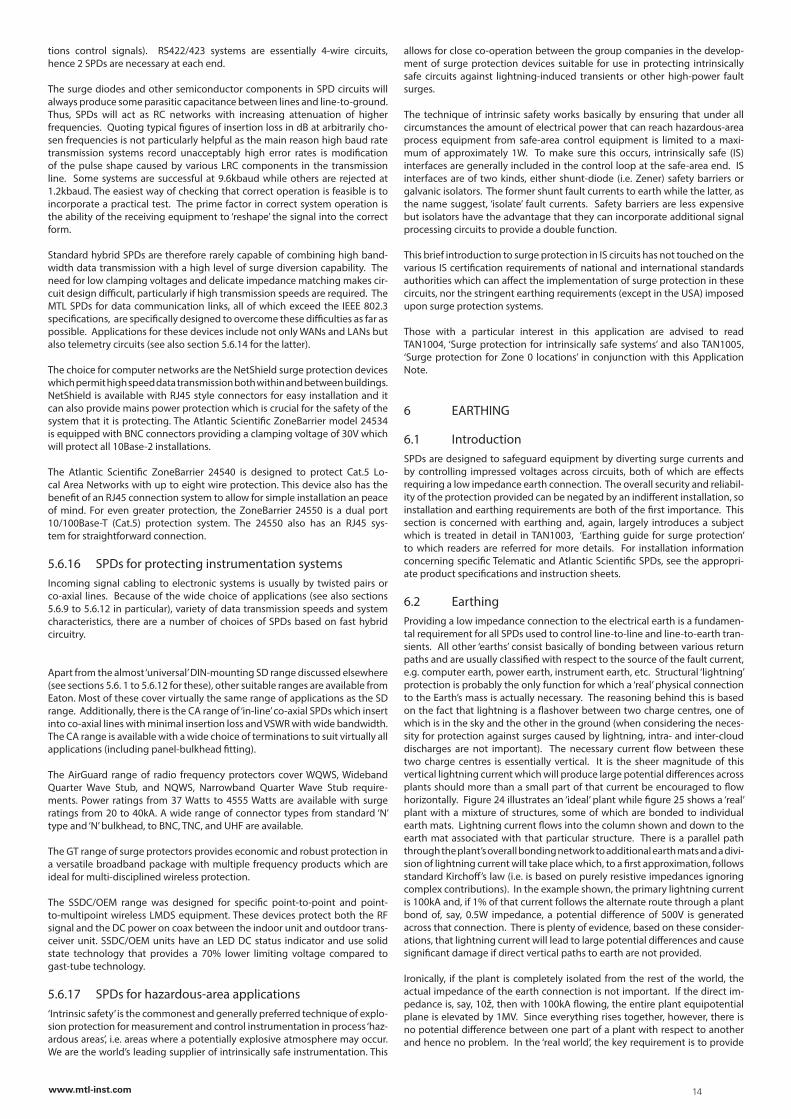
tions control signals). RS422/423 systems are essentially 4-wire circuits, hence 2 SPDs are necessary at each end.
The surge diodes and other semiconductor components in SPD circuits will always produce some parasitic capacitance between lines and line-to-ground. Thus, SPDs will act as RC networks with increasing attenuation of higher frequencies. Quoting typical figures of insertion loss in dB at arbitrarily cho-sen frequencies is not particularly helpful as the main reason high baud rate transmission systems record unacceptably high error rates is modification of the pulse shape caused by various LRC components in the transmission line. Some systems are successful at 9.6kbaud while others are rejected at 1.2kbaud. The easiest way of checking that correct operation is feasible is to incorporate a practical test. The prime factor in correct system operation is the ability of the receiving equipment to ‘reshape’ the signal into the correct form.
Standard hybrid SPDs are therefore rarely capable of combining high band-width data transmission with a high level of surge diversion capability. The need for low clamping voltages and delicate impedance matching makes cir-cuit design difficult, particularly if high transmission speeds are required. The MTL SPDs for data communication links, all of which exceed the IEEE 802.3 specifications, are specifically designed to overcome these difficulties as far as possible. Applications for these devices include not only WANs and LANs but also telemetry circuits (see also section 5.6.14 for the latter).
The choice for computer networks are the NetShield surge protection devices which permit high speed data transmission both within and between buildings. NetShield is available with RJ45 style connectors for easy installation and it can also provide mains power protection which is crucial for the safety of the system that it is protecting. The Atlantic Scientific ZoneBarrier model 24534 is equipped with BNC connectors providing a clamping voltage of 30V which will protect all 10Base-2 installations.
The Atlantic Scientific ZoneBarrier 24540 is designed to protect Cat.5 Lo-cal Area Networks with up to eight wire protection. This device also has the benefit of an RJ45 connection system to allow for simple installation an peace of mind. For even greater protection, the ZoneBarrier 24550 is a dual port 10/100Base-T (Cat.5) protection system. The 24550 also has an RJ45 sys-tem for straightforward connection.
5.6.16 SPDs for protecting instrumentation systemsIncoming signal cabling to electronic systems is usually by twisted pairs or co-axial lines. Because of the wide choice of applications (see also sections 5.6.9 to 5.6.12 in particular), variety of data transmission speeds and system characteristics, there are a number of choices of SPDs based on fast hybrid circuitry.
Apart from the almost ‘universal’ DIN-mounting SD range discussed elsewhere (see sections 5.6. 1 to 5.6.12 for these), other suitable ranges are available from Eaton. Most of these cover virtually the same range of applications as the SD range. Additionally, there is the CA range of ‘in-line’ co-axial SPDs which insert into co-axial lines with minimal insertion loss and VSWR with wide bandwidth. The CA range is available with a wide choice of terminations to suit virtually all applications (including panel-bulkhead fitting).
The AirGuard range of radio frequency protectors cover WQWS, Wideband Quarter Wave Stub, and NQWS, Narrowband Quarter Wave Stub require-ments. Power ratings from 37 Watts to 4555 Watts are available with surge ratings from 20 to 40kA. A wide range of connector types from standard ‘N’ type and ‘N’ bulkhead, to BNC, TNC, and UHF are available.
The GT range of surge protectors provides economic and robust protection in a versatile broadband package with multiple frequency products which are ideal for multi-disciplined wireless protection.
The SSDC/OEM range was designed for specific point-to-point and point-to-multipoint wireless LMDS equipment. These devices protect both the RF signal and the DC power on coax between the indoor unit and outdoor trans-ceiver unit. SSDC/OEM units have an LED DC status indicator and use solid state technology that provides a 70% lower limiting voltage compared to gast-tube technology.
5.6.17 SPDs for hazardous-area applications‘Intrinsic safety’ is the commonest and generally preferred technique of explo-sion protection for measurement and control instrumentation in process ‘haz-ardous areas’, i.e. areas where a potentially explosive atmosphere may occur. We are the world’s leading supplier of intrinsically safe instrumentation. This
allows for close co-operation between the group companies in the develop-ment of surge protection devices suitable for use in protecting intrinsically safe circuits against lightning-induced transients or other high-power fault surges.
The technique of intrinsic safety works basically by ensuring that under all circumstances the amount of electrical power that can reach hazardous-area process equipment from safe-area control equipment is limited to a maxi-mum of approximately 1W. To make sure this occurs, intrinsically safe (IS) interfaces are generally included in the control loop at the safe-area end. IS interfaces are of two kinds, either shunt-diode (i.e. Zener) safety barriers or galvanic isolators. The former shunt fault currents to earth while the latter, as the name suggest, ‘isolate’ fault currents. Safety barriers are less expensive but isolators have the advantage that they can incorporate additional signal processing circuits to provide a double function.
This brief introduction to surge protection in IS circuits has not touched on the various IS certification requirements of national and international standards authorities which can affect the implementation of surge protection in these circuits, nor the stringent earthing requirements (except in the USA) imposed upon surge protection systems.
Those with a particular interest in this application are advised to read TAN1004, ‘Surge protection for intrinsically safe systems’ and also TAN1005, ‘Surge protection for Zone 0 locations’ in conjunction with this Application Note.
6 EARTHING
6.1 IntroductionSPDs are designed to safeguard equipment by diverting surge currents and by controlling impressed voltages across circuits, both of which are effects requiring a low impedance earth connection. The overall security and reliabil-ity of the protection provided can be negated by an indifferent installation, so installation and earthing requirements are both of the first importance. This section is concerned with earthing and, again, largely introduces a subject which is treated in detail in TAN1003, ‘Earthing guide for surge protection’ to which readers are referred for more details. For installation information concerning specific Telematic and Atlantic Scientific SPDs, see the appropri-ate product specifications and instruction sheets.
6.2 EarthingProviding a low impedance connection to the electrical earth is a fundamen-tal requirement for all SPDs used to control line-to-line and line-to-earth tran-sients. All other ‘earths’ consist basically of bonding between various return paths and are usually classified with respect to the source of the fault current, e.g. computer earth, power earth, instrument earth, etc. Structural ‘lightning’ protection is probably the only function for which a ‘real’ physical connection to the Earth’s mass is actually necessary. The reasoning behind this is based on the fact that lightning is a flashover between two charge centres, one of which is in the sky and the other in the ground (when considering the neces-sity for protection against surges caused by lightning, intra- and inter-cloud discharges are not important). The necessary current flow between these two charge centres is essentially vertical. It is the sheer magnitude of this vertical lightning current which will produce large potential differences across plants should more than a small part of that current be encouraged to flow horizontally. Figure 24 illustrates an ‘ideal’ plant while figure 25 shows a ‘real’ plant with a mixture of structures, some of which are bonded to individual earth mats. Lightning current flows into the column shown and down to the earth mat associated with that particular structure. There is a parallel path through the plant’s overall bonding network to additional earth mats and a divi-sion of lightning current will take place which, to a first approximation, follows standard Kirchoff’s law (i.e. is based on purely resistive impedances ignoring complex contributions). In the example shown, the primary lightning current is 100kA and, if 1% of that current follows the alternate route through a plant bond of, say, 0.5W impedance, a potential difference of 500V is generated across that connection. There is plenty of evidence, based on these consider-ations, that lightning current will lead to large potential differences and cause significant damage if direct vertical paths to earth are not provided.
Ironically, if the plant is completely isolated from the rest of the world, the actual impedance of the earth connection is not important. If the direct im-pedance is, say, 10ž, then with 100kA flowing, the entire plant equipotential plane is elevated by 1MV. Since everything rises together, however, there is no potential difference between one part of a plant with respect to another and hence no problem. In the ‘real world’, the key requirement is to provide
14www.mtl-inst.com
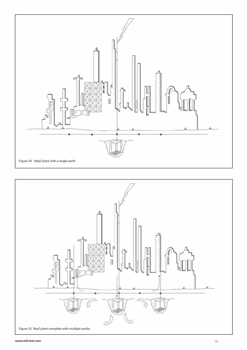
Figure 24 ‘Ideal’ plant with a single earth
Figure 25 ‘Real’ plant complete with multiple earths
15www.mtl-inst.com
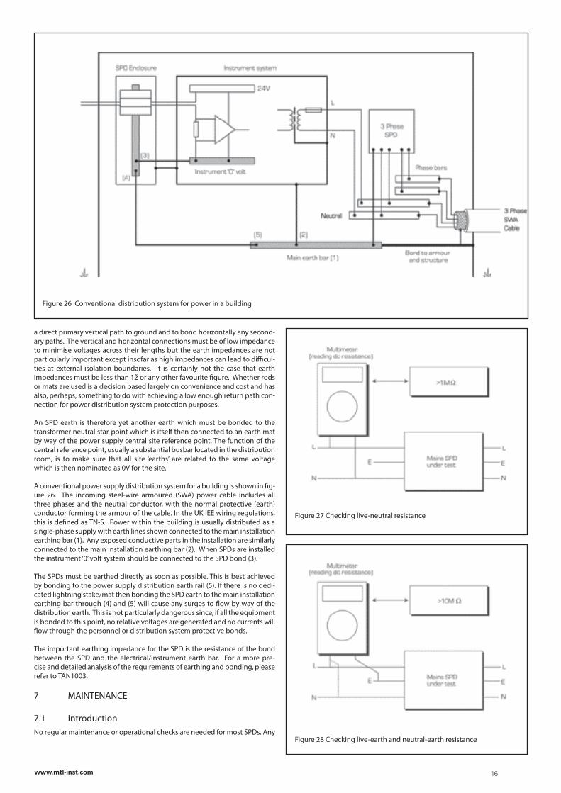
a direct primary vertical path to ground and to bond horizontally any second-ary paths. The vertical and horizontal connections must be of low impedance to minimise voltages across their lengths but the earth impedances are not particularly important except insofar as high impedances can lead to difficul-ties at external isolation boundaries. It is certainly not the case that earth impedances must be less than 1ž or any other favourite figure. Whether rods or mats are used is a decision based largely on convenience and cost and has also, perhaps, something to do with achieving a low enough return path con-nection for power distribution system protection purposes.
An SPD earth is therefore yet another earth which must be bonded to the transformer neutral star-point which is itself then connected to an earth mat by way of the power supply central site reference point. The function of the central reference point, usually a substantial busbar located in the distribution room, is to make sure that all site ‘earths’ are related to the same voltage which is then nominated as 0V for the site.
A conventional power supply distribution system for a building is shown in fig-ure 26. The incoming steel-wire armoured (SWA) power cable includes all three phases and the neutral conductor, with the normal protective (earth) conductor forming the armour of the cable. In the UK IEE wiring regulations, this is defined as TN-S. Power within the building is usually distributed as a single-phase supply with earth lines shown connected to the main installation earthing bar (1). Any exposed conductive parts in the installation are similarly connected to the main installation earthing bar (2). When SPDs are installed the instrument ‘0’ volt system should be connected to the SPD bond (3).
The SPDs must be earthed directly as soon as possible. This is best achieved by bonding to the power supply distribution earth rail (5). If there is no dedi-cated lightning stake/mat then bonding the SPD earth to the main installation earthing bar through (4) and (5) will cause any surges to flow by way of the distribution earth. This is not particularly dangerous since, if all the equipment is bonded to this point, no relative voltages are generated and no currents will flow through the personnel or distribution system protective bonds.
The important earthing impedance for the SPD is the resistance of the bond between the SPD and the electrical/instrument earth bar. For a more pre-cise and detailed analysis of the requirements of earthing and bonding, please refer to TAN1003.
7 MAINTENANCE
7.1 IntroductionNo regular maintenance or operational checks are needed for most SPDs. Any
Figure 26 Conventional distribution system for power in a building
Figure 27 Checking live-neutral resistance
Figure 28 Checking live-earth and neutral-earth resistance
16www.mtl-inst.com
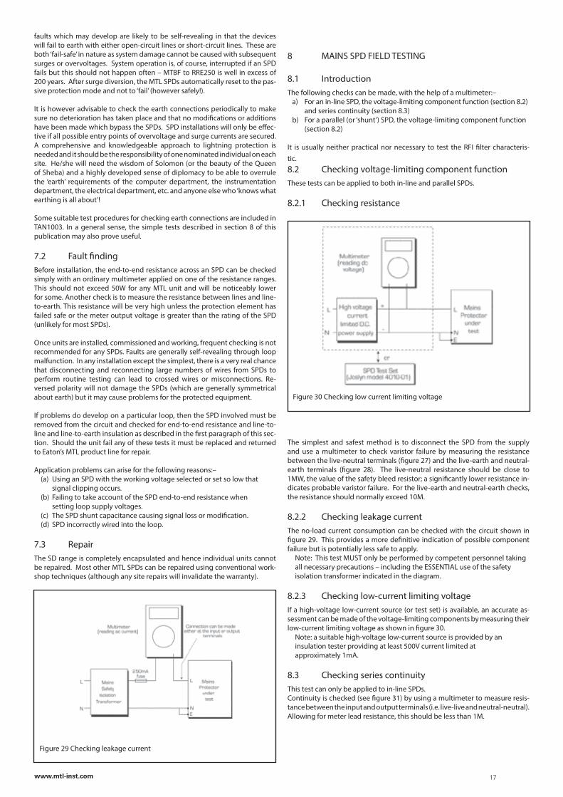
faults which may develop are likely to be self-revealing in that the devices will fail to earth with either open-circuit lines or short-circuit lines. These are both ‘fail-safe’ in nature as system damage cannot be caused with subsequent surges or overvoltages. System operation is, of course, interrupted if an SPD fails but this should not happen often – MTBF to RRE250 is well in excess of 200 years. After surge diversion, the MTL SPDs automatically reset to the pas-sive protection mode and not to ‘fail’ (however safely!).
It is however advisable to check the earth connections periodically to make sure no deterioration has taken place and that no modifications or additions have been made which bypass the SPDs. SPD installations will only be effec-tive if all possible entry points of overvoltage and surge currents are secured. A comprehensive and knowledgeable approach to lightning protection is needed and it should be the responsibility of one nominated individual on each site. He/she will need the wisdom of Solomon (or the beauty of the Queen of Sheba) and a highly developed sense of diplomacy to be able to overrule the ‘earth’ requirements of the computer department, the instrumentation department, the electrical department, etc. and anyone else who ‘knows what earthing is all about’!
Some suitable test procedures for checking earth connections are included in TAN1003. In a general sense, the simple tests described in section 8 of this publication may also prove useful.
7.2 Fault findingBefore installation, the end-to-end resistance across an SPD can be checked simply with an ordinary multimeter applied on one of the resistance ranges. This should not exceed 50W for any MTL unit and will be noticeably lower for some. Another check is to measure the resistance between lines and line-to-earth. This resistance will be very high unless the protection element has failed safe or the meter output voltage is greater than the rating of the SPD (unlikely for most SPDs).
Once units are installed, commissioned and working, frequent checking is not recommended for any SPDs. Faults are generally self-revealing through loop malfunction. In any installation except the simplest, there is a very real chance that disconnecting and reconnecting large numbers of wires from SPDs to perform routine testing can lead to crossed wires or misconnections. Re-versed polarity will not damage the SPDs (which are generally symmetrical about earth) but it may cause problems for the protected equipment.
If problems do develop on a particular loop, then the SPD involved must be removed from the circuit and checked for end-to-end resistance and line-to-line and line-to-earth insulation as described in the first paragraph of this sec-tion. Should the unit fail any of these tests it must be replaced and returned to Eaton’s MTL product line for repair.
Application problems can arise for the following reasons:– (a) Using an SPD with the working voltage selected or set so low that signal clipping occurs. (b) Failing to take account of the SPD end-to-end resistance when setting loop supply voltages. (c) The SPD shunt capacitance causing signal loss or modification. (d) SPD incorrectly wired into the loop.
7.3 RepairThe SD range is completely encapsulated and hence individual units cannot be repaired. Most other MTL SPDs can be repaired using conventional work-shop techniques (although any site repairs will invalidate the warranty).
Figure 29 Checking leakage current
8 MAINS SPD FIELD TESTING
8.1 IntroductionThe following checks can be made, with the help of a multimeter:– a) For an in-line SPD, the voltage-limiting component function (section 8.2) and series continuity (section 8.3) b) For a parallel (or ‘shunt’) SPD, the voltage-limiting component function (section 8.2)
It is usually neither practical nor necessary to test the RFI filter characteris-tic.8.2 Checking voltage-limiting component functionThese tests can be applied to both in-line and parallel SPDs.
8.2.1 Checking resistance
The simplest and safest method is to disconnect the SPD from the supply and use a multimeter to check varistor failure by measuring the resistance between the live-neutral terminals (figure 27) and the live-earth and neutral-earth terminals (figure 28). The live-neutral resistance should be close to 1MW, the value of the safety bleed resistor; a significantly lower resistance in-dicates probable varistor failure. For the live-earth and neutral-earth checks, the resistance should normally exceed 10M.
8.2.2 Checking leakage currentThe no-load current consumption can be checked with the circuit shown in figure 29. This provides a more definitive indication of possible component failure but is potentially less safe to apply. Note: This test MUST only be performed by competent personnel taking all necessary precautions – including the ESSENTIAL use of the safety isolation transformer indicated in the diagram.
8.2.3 Checking low-current limiting voltageIf a high-voltage low-current source (or test set) is available, an accurate as-sessment can be made of the voltage-limiting components by measuring their low-current limiting voltage as shown in figure 30. Note: a suitable high-voltage low-current source is provided by an insulation tester providing at least 500V current limited at approximately 1mA.
8.3 Checking series continuityThis test can only be applied to in-line SPDs.Continuity is checked (see figure 31) by using a multimeter to measure resis-tance between the input and output terminals (i.e. live-live and neutral-neutral). Allowing for meter lead resistance, this should be less than 1M.
Figure 30 Checking low current limiting voltage
17www.mtl-inst.com

EUROPE (EMEA):
+44 (0)1582 723633 [email protected]
THE AMERICAS:
+1 800 835 7075 [email protected]
ASIA-PACIFIC:
+65 6 645 9888 [email protected]
The given data is only intended as a product description and should not be regarded as a legal warranty of properties or guarantee. In the interest of further technical developments, we reserve the right to make design changes.
Eaton Electric Limited, Great Marlings, Butterfield, LutonBeds, LU2 8DL, UK.Tel: + 44 (0)1582 723633 Fax: + 44 (0)1582 422283E-mail: [email protected]
© 2016 EatonAll Rights ReservedPublication No. AN904-1002 Rev I 211016 October 2016
AUSTRALIAMTL Instruments Pty Ltd, 10 Kent Road, Mascot, New South Wales, 2020, Australia
Tel: +61 1300 308 374 Fax: +61 1300 308 463E-mail: [email protected]
BeNeLuxMTL Instruments BVAmbacht 6, 5301 KW ZaltbommelThe Netherlands
Tel: +31 (0)418 570290 Fax: +31 (0)418 541044E-mail: [email protected]
CHINACooper Electric (Shanghai) Co. Ltd955 Shengli Road, Heqing Industrial ParkPudong New Area, Shanghai 201201
Tel: +86 21 2899 3817 Fax: +86 21 2899 3992E-mail: [email protected]
FRANCEMTL Instruments sarl,7 rue des Rosiéristes, 69410 Champagne au Mont d’OrFrance
Tel: +33 (0)4 37 46 16 53 Fax: +33 (0)4 37 46 17 20E-mail: [email protected]
GERMANYMTL Instruments GmbH, Heinrich-Hertz-Str. 12, 50170 Kerpen, Germany
Tel: +49 (0)22 73 98 12 - 0 Fax: +49 (0)22 73 98 12 - 2 00E-mail: [email protected]
INDIAMTL India, No.36, Nehru Street, Off Old Mahabalipuram RoadSholinganallur, Chennai - 600 119, India
Tel: +91 (0) 44 24501660 /24501857 Fax: +91 (0) 44 24501463E-mail: [email protected]
ITALYMTL Italia srl, Via San Bovio, 3, 20090 Segrate, Milano, Italy
Tel: +39 02 959501 Fax: +39 02 95950759E-mail: [email protected]
JAPANCooper Crouse-Hinds Japan KK, MT Building 3F, 2-7-5 Shiba Daimon, Minato-ku,Tokyo, Japan 105-0012
Tel: +81 (0)3 6430 3128 Fax: +81 (0)3 6430 3129E-mail: [email protected]
NORWAYNorex ASFekjan 7c, Postboks 147, N-1378 Nesbru, Norway
Tel: +47 66 77 43 80 Fax: +47 66 84 55 33E-mail: [email protected]
RUSSIACooper Industries Russia LLCElektrozavodskaya Str 33Building 4Moscow 107076, Russia
Tel: +7 (495) 981 3770 Fax: +7 (495) 981 3771E-mail: [email protected]
SINGAPORECooper Crouse-Hinds Pte LtdNo 2 Serangoon North Avenue 5, #06-01 Fu Yu BuildingSingapore 554911
Tel: +65 6 645 9864 / 5 Fax: +65 6 487 7997E-mail: [email protected]
SOUTH KOREACooper Crouse-Hinds Korea7F. Parkland Building 237-11 Nonhyun-dong Gangnam-gu,Seoul 135-546, South Korea.
Tel: +82 6380 4805 Fax: +82 6380 4839E-mail: [email protected]
UNITED ARAB EMIRATESCooper Industries/Eaton Corporation Office 205/206, 2nd Floor SJ Towers, off. Old Airport Road, Abu Dhabi, United Arab Emirates
Tel: +971 2 44 66 840 Fax: +971 2 44 66 841E-mail: [email protected]
UNITED KINGDOMEaton Electric Ltd, Great Marlings, Butterfield, LutonBeds LU2 8DL
Tel: +44 (0)1582 723633 Fax: +44 (0)1582 422283E-mail: [email protected]
AMERICASCooper Crouse-Hinds MTL Inc. 3413 N. Sam Houston Parkway W.Suite 200, Houston TX 77086, USA
Tel: +1 281-571-8065 Fax: +1 281-571-8069E-mail: [email protected]