Embed Size (px)
Citation preview
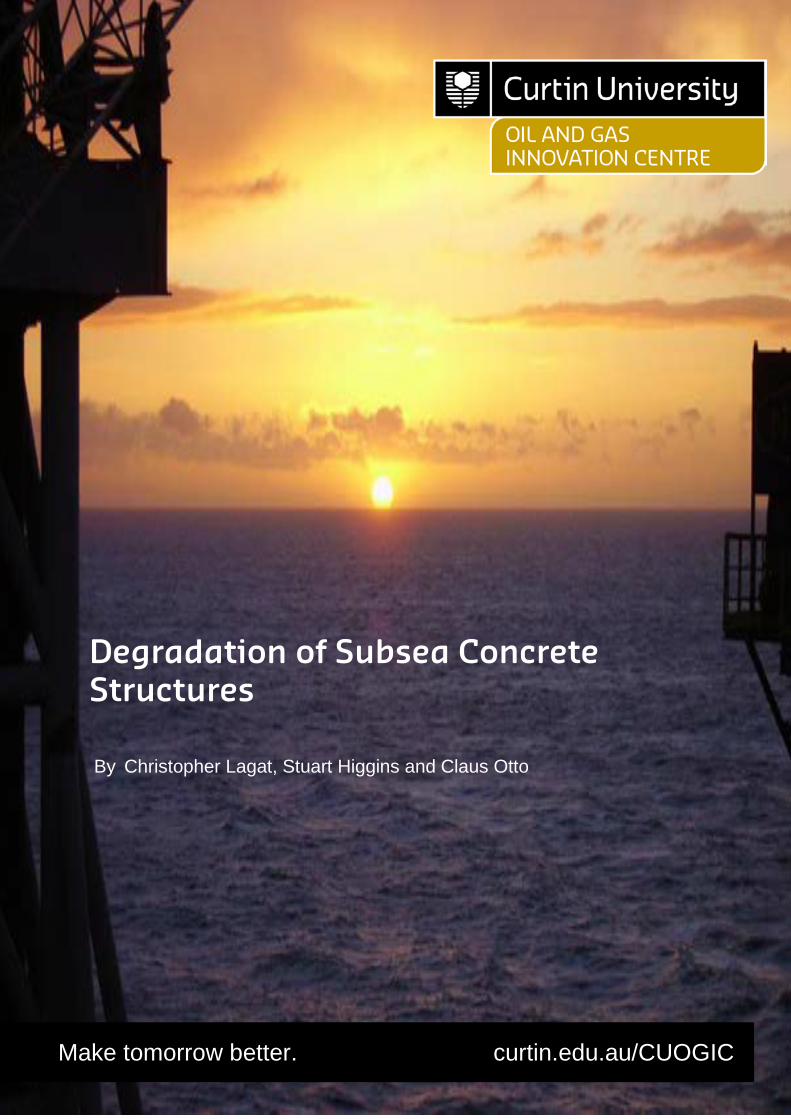
Degradation of Subsea Concreate Structures 2019
Degradation of Subsea Concrete Structures
By Christopher Lagat, Stuart Higgins and Claus Otto
Make tomorrow better. curtin.edu.au/CUOGIC

i
Acknowledgement
The authors wish to acknowledge Warren Green, Director and a Principal Corrosion Engineer at Vinsi Partners (and also an Adjunct Associate Professor at the Curtin Corrosion Centre), for reviewing the paper and sharing information on concrete corrosion. The authors also express their gratitude to Andrew Peek, Technical Director, Materials Technology at GHD, for reviewing the paper and providing some insights on concrete durability assessment of Wandoo B concrete gravity structure. All rights reserved. Apart from fair dealing for the purposes permitted under the Copyright Act 1968 (Cth), no part of this material may be reproduced, stored or transmitted in any form or by any means without the prior permission in writing of Curtin University. © Curtin University 2019
ii
Executive Summary
The main forms of deterioration of the CGBSs include chemical deterioration, corrosion of steel reinforcement and pre-stressing tendons, bacterial degradation, scour and settlement. Carbonation-induced and chloride induced corrosion is deemed to be the most serious problem that affect the durability of marine concrete structures. It is widely accepted that the deterioration of a CGBS to the point where it may result in structural instability could take hundreds of years. The concrete durability assessment of the Wandoo B CGBS was carried out by an independent consultant in 2015, 18 years after being in operation. No significant defects were observed. The structure was found to be structurally sound. Decommissioning alternatives for the CGBSs include complete removal by refloat or by offshore demolition, partial removal and leave “as-is”. Existing international legal frameworks that provide guidelines on decommissioning of offshore oil and gas installations and structures include the United Nations Convention on the Law of the Sea (UNCLOS) and the London Convention on the Prevention of Pollution by Dumping of Wastes and other Matter. Regional regulations include the Oslo Convention on the Prevention of Marine Pollution, Oslo Commission (OSCOM) treaty for the for the Disposal of Offshore Platforms at Sea, the Oslo/Paris Commission (OSPAR) Convention for the Protection of the Marine Environment of the North East Atlantic and the EU Regulation 259/93 on the Supervision and Control of Shipments of Waste within, into or out of the European Community. The international and regional legislations require that offshore installations and structures are removed at the end life of field. These regulations are also subject to other provisions of national legislations. In Australia, for instance, the Offshore Petroleum and Greenhouse Gas Storage (OPGGS) Act 2006, in conjunction with the UNCLOS and London Convention, provides guidelines for decommissioning offshore installations. The 2018 Offshore Petroleum Decommissioning Guideline supports the provisions of the OPGGS act. The decommissioning of aged CGBS presents a number of risks related to technical feasibility, cost, personnel safety and environmental impact. In determining the best decommissioning option for the CGBS platforms, a balance has to be struck between technical difficulty, safety for personnel, the impact on the environment and costs. The toppling over of large concrete gravity structures has never been done, hence this option will be subject to large uncertainties. Equally, the CGBS refloat or complete removal option presents considerable risks. Therefore, the leave in situ alternative may currently be claimed to be the best option for CGBSs.
iii
Table of Contents
ACKNOWLEDGEMENT ....................................................................................................................................... I
EXECUTIVE SUMMARY ..................................................................................................................................... II
TABLE OF CONTENTS .......................................................................................................................................III
ACRONYMS ..................................................................................................................................................... V
1. INTRODUCTION ...................................................................................................................................... 1
1.1. AIM ....................................................................................................................................................... 1 1.2. PROJECT APPROACH .................................................................................................................................. 2 1.3. PROJECT TEAM ........................................................................................................................................ 2 1.4. REPORT STRUCTURE .................................................................................................................................. 2
2. CONCRETE GRAVITY STRUCTURES .......................................................................................................... 3
2.1. INTRODUCTION ........................................................................................................................................ 3 2.2. CONSTRUCTION AND INSTALLATION .............................................................................................................. 3 2.3. SELECTION OF CONCRETE GRAVITY STRUCTURE OPTION ................................................................................... 4 2.4. CONCRETE GRAVITY STRUCTURES IN AUSTRALIA ............................................................................................. 4
2.4.1. West Tuna and Bream B Platforms ................................................................................................. 5 2.4.2. Wandoo B Platform ........................................................................................................................ 5
3. CONCRETE FOR MARINE STRUCTURES .................................................................................................... 7
3.1. INTRODUCTION ........................................................................................................................................ 7 3.2. CONCRETE PROTECTION ............................................................................................................................. 7 3.3. CONCRETE EXPOSURE CLASSIFICATION AND CONCRETE STRENGTH ..................................................................... 7
4. DETERIORATION OF SUBSEA CONCRETE GRAVITY BASE STRUCTURES .................................................... 9
4.1. ALKALI-AGGREGATE REACTION ................................................................................................................... 9 4.2. STEEL REINFORCEMENT CORROSION............................................................................................................. 9 4.3. CHEMICAL ATTACK .................................................................................................................................. 10 4.4. BACTERIAL DEGRADATION ........................................................................................................................ 10 4.5. FATIGUE ............................................................................................................................................... 11
5. CONCRETE DURABILITY ASSESSMENT REVIEW OF WANDOO B CONCRETE GRAVITY BASE STRUCTURE. 12
5.1. ASSESSMENT OF SHAFTS ABOVE WATER LEVEL ............................................................................................. 12 5.2. ASSESSMENT OF CAISSON AND SHAFTS BELOW WATER LEVEL .......................................................................... 13 5.3. CONCLUSION ......................................................................................................................................... 13
6. OFFSHORE OIL AND GAS ASSETS DECOMMISSIONING REGULATIONS................................................... 13
6.1. INTERNATIONAL DECOMMISSIONING LEGAL FRAMEWORK .............................................................................. 14 6.2. AUSTRALIA’S DECOMMISSIONING LEGAL FRAMEWORK .................................................................................. 15
7. DECOMMISSIONING OPTIONS .............................................................................................................. 17
7.1. LEAVE IN SITU ........................................................................................................................................ 17 7.2. PARTIAL REMOVAL .................................................................................................................................. 17 7.3. COMPLETE REMOVAL .............................................................................................................................. 18
8. RISKS ASSOCIATED WITH DECOMMISSIONING OF AGING AND DEGRADED SUBSEA CONCRETE STRUCTURES .................................................................................................................................................. 19
8.1. TECHNICAL FEASIBILITY ............................................................................................................................ 19 8.1.1. Structural integrity ........................................................................................................................ 19 8.1.2. Jacking .......................................................................................................................................... 19 8.1.3. Weight .......................................................................................................................................... 19 8.1.4. Buoyancy ....................................................................................................................................... 19

iv
8.1.5. Time and weather ......................................................................................................................... 19 8.1.6. Mechanical cutting ....................................................................................................................... 19 8.1.7. Explosive charges .......................................................................................................................... 20 8.1.8. Lifting ............................................................................................................................................ 20
8.2. COST .................................................................................................................................................... 20 8.3. RISK TO PERSONNEL ................................................................................................................................ 20 8.4. ENVIRONMENTAL AND SOCIETAL IMPACTS ................................................................................................... 20
9. CONCLUSION ........................................................................................................................................ 22
REFERENCES ................................................................................................................................................... 24
APPENDICES................................................................................................................................................... 26
v
Acronyms
CGBS Concrete gravity base structure
SSCV Semi-submersible crane vessels
VLSSCV Very large semi-submersible crane vessel
SCM Supplementary Cementitious Material
VPV Volume of permeable voids
AAR Alkali-aggregate reactivity
ASR Alkali-silica reaction
UNCLOS United Nations Convention on the Law of the Sea
IMO International Maritime Organization
OSCOM Oslo Commission
OSPAR Oslo/Paris Commission
UKCS UK continental shelf
OPGGS Offshore Petroleum and Greenhouse Gas Storage
NOPSEMA Offshore Petroleum Safety and Environmental Management Authority
PUND Undeveloped
PDEV Developed
ZDEP Depleted
G Gas field
O Oil field
OG Oil and gas field
GC Gas and condensate field
1
1. Introduction
Many offshore oil and gas fields are approaching the end of their economic life. Hence the decommissioning of offshore platforms is an issue of growing concern. In the past 50 years, over 10,000 offshore facilities have been installed worldwide. These installations include steel or concrete platforms, floating production systems - storage and loading facilities, subsea production systems and pipelines. Each of the installations presents its own challenges in terms of water depth, type and size. Platforms in shallower waters typically weigh less than 5,000 tonnes and the largest reinforced concrete platforms in deep waters weigh over 200,000 tonnes. Decommissioning is an integral part of the oil and gas production cycle. The offshore installations are situated in waters which have many other social and commercial uses and the installations handle substances which could have an impact on the environment. Consequently, the environmental sensitivity to decommissioning arrangements is considerable. A balance has to be struck between the impact on the environment, costs, technical difficulty and safety in determining the best strategy for decommissioning and installation [1]. The offshore decommissioning scope of work which will have to be undertaken by operators relate to four basic classes of installation - Fixed Platforms, Moored or Tethered Platforms, Pipelines and Subsea Structures. The fixed platforms (jackets and concrete gravity base structures) present the greatest difficulty in decommissioning. The concrete gravity base structure (CGBS) platforms are far fewer in number but are one or two orders of magnitude heavier than their depth-equivalent steel jackets. These structures were pioneered in the North Sea. The first CGBS to be installed was the Ekofisk Tank in Norwegian waters in 1973. More CGBSs have since been installed in the North Sea, West Africa, the Gulf of Mexico, Brazil, Northern Canada, Netherlands, Australia and the Sea of Java [2]. Aging and deterioration of the concrete structures in marine environments is one of the most pressing problems facing the oil and gas industry. While recent advancements in concrete technology have made it easier to control the negative impact of deteriorating processes such as alkali-aggregate reaction and chemical attack, chloride-induced corrosion of embedded steel continues to pose the biggest threat to durability and performance of structures. The aging subsea concrete structures present particularly difficult problems for decommissioning. Removal of topsides modules can be achieved by Semi-submersible crane vessels (SSCV) or very large semi-submersible crane vessels (VLSSCVs) as for steel jacket platforms. Any proposed decommissioning operation for the subsea concrete structures must endeavor to minimize the associated hazards and risks to personnel to a level that is as low as reasonably practicable [3].
1.1. Aim
The report outlines a position on the feasibility and risk of leaving CGBSs "in-place" as a decommissioning option.
2
1.2. Project Approach
The current understanding of aging and degradation of subsea concrete structures was reviewed and assessed. A review of concrete gravity base structures in Australia was also conducted.
The process of decommissioning is regulated by international and national legislations. The current relevant Australian and international decommissioning regulations were reviewed. The risks associated with aging and degradation of subsea concrete structures were evaluated. This will inform the selection of possible decommissioning options which include removal or leaving “as-is”.
Industry experts were contacted or “interviewed” for further clarity on the aging and deterioration of subsea concrete structures. The outcome of the project was peer reviewed.
1.3. Project Team
The project team consisted of Professor Claus Otto, Assoc. Professor Stuart Higgins and Dr Christopher Lagat of Curtin University.
1.4. Report Structure
The structure of the report is outlined below:
1. Introduction.
2. Concrete gravity base structures.
3. Concrete for marine structures.
4. Degradation and aging of concrete gravity base structures.
5. Concrete durability assessment review of Wandoo B CGBS.
6. Offshore oil and gas assets decommissioning regulatory framework.
7. Risks associated with decommissioning of aging and degraded subsea concrete structures.
8. Decommissioning options for CGBSs.
9. Conclusion. 10. Acknowledgement.
3
2. Concrete Gravity Structures
2.1. Introduction
Concrete Gravity Base Structures have been used in the oil and gas industry since the early nineteen seventies. Several structures have been installed worldwide at various water depths. The majority of these structures are installed in the OSPAR maritime region which covers the whole of the North East Atlantic area including the North Sea. Other areas where CGBSs have been installed include Australia, the Philippines, Canada and the Baltic [4]. A CGBS platform is placed on the seabed and is held in place by its own weight. The CGBS has a large weight and a large area to resist environmental forces and overturning moments during its lifetime. Additionally, the majority of the platforms are stabilised by skirts that penetrate into the seabed. The early development of concrete gravity platforms in the 1970s was driven by the generic requirement to store large volumes of oil and support heavy topsides in deep waters. Several CGBS platform designs have been developed since the seventies. Most of the platforms have a base caisson (normally for storage of oil) and shafts to support the topsides. The shafts generally serve as drilling shafts or contain utility systems for offloading, and ballast operations. There are three main types of concrete gravity structures [4]:
• Tower and caisson types with circular caisson cells (Condeep- with one, two, three or four columns).
• Tower and caisson types with rectangular caisson cells (Sea Tank, Andoc, Ove Arup and several small platforms designed by French, British and Dutch companies).
• Jarlan wall types (Doris). The structure is surrounded by a perforated breakwater wall (Jarlan patent).
The first CGBS platform to be installed, the Ekofisk Tank, was a Doris type platform.
2.2. Construction and installation
The caisson part of the CGBS is built in a dry dock. When this lower part has been concreted to a certain height, the substructure is floated out of the dry dock and moored at an inshore deep-water site. The pouring of concrete continues. The structure is continuously ballasted down to maintain a workable height as the construction advances. Thereafter the shafts are fitted. The CGBS substructure is ballasted with water so that only about 5 metres of the shafts protrude above water. Barges then position the topsides over the shafts. The substructure is then de-ballasted and slowly the weight of the topsides is transferred onto the caisson and shafts. The whole platform is then transported to the offshore field and installed. The first generation of offshore concrete gravity platforms installed prior to 1979 were not designed or constructed for future removal operations. Provisions for re-floating were later incorporated into the design of the 2nd generation concrete platforms [4]. The Ravenspurn North CGBS, designed by Arup Energy and installed in 1989, was the first new style of "lightweight" concrete platform. The platform was exceedingly smaller than the earlier versions as it was not designed for oil storage or topside transportation. The reduced size permitted the platform to be entirely constructed within a dry dock. The topsides were installed offshore using a heavy-lift vessel. This 2nd generation CGBSs by Arup Energy are designed for ease of decommissioning and can be returned to inshore waters for dismantling and recycling.
4
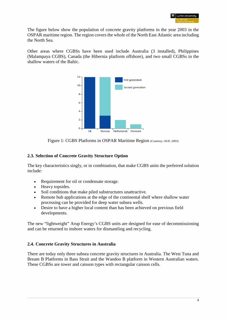
The figure below show the population of concrete gravity platforms in the year 2003 in the OSPAR maritime region. The region covers the whole of the North East Atlantic area including the North Sea. Other areas where CGBSs have been used include Australia (3 installed), Philippines (Malampaya CGBS), Canada (the Hibernia platform offshore), and two small CGBSs in the shallow waters of the Baltic.
Figure 1: CGBS Platforms in OSPAR Maritime Region (Courtesy, OGP, 2003)
2.3. Selection of Concrete Gravity Structure Option
The key characteristics singly, or in combination, that make CGBS units the preferred solution include:
• Requirement for oil or condensate storage. • Heavy topsides. • Soil conditions that make piled substructures unattractive. • Remote hub applications at the edge of the continental shelf where shallow water
processing can be provided for deep water subsea wells. • Desire to have a higher local content than has been achieved on previous field
developments.
The new “lightweight” Arup Energy’s CGBS units are designed for ease of decommissioning and can be returned to inshore waters for dismantling and recycling.
2.4. Concrete Gravity Structures in Australia
There are today only three subsea concrete gravity structures in Australia. The West Tuna and Bream B Platforms in Bass Strait and the Wandoo B platform in Western Australian waters. These CGBSs are tower and caisson types with rectangular caisson cells.
5
2.4.1. West Tuna and Bream B Platforms
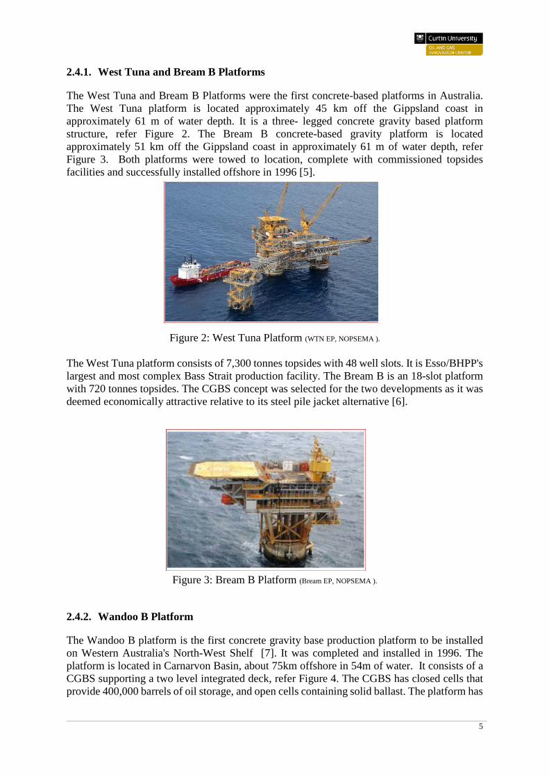
The West Tuna and Bream B Platforms were the first concrete-based platforms in Australia. The West Tuna platform is located approximately 45 km off the Gippsland coast in approximately 61 m of water depth. It is a three- legged concrete gravity based platform structure, refer Figure 2. The Bream B concrete-based gravity platform is located approximately 51 km off the Gippsland coast in approximately 61 m of water depth, refer Figure 3. Both platforms were towed to location, complete with commissioned topsides facilities and successfully installed offshore in 1996 [5].
Figure 2: West Tuna Platform (WTN EP, NOPSEMA ). The West Tuna platform consists of 7,300 tonnes topsides with 48 well slots. It is Esso/BHPP's largest and most complex Bass Strait production facility. The Bream B is an 18-slot platform with 720 tonnes topsides. The CGBS concept was selected for the two developments as it was deemed economically attractive relative to its steel pile jacket alternative [6].
Figure 3: Bream B Platform (Bream EP, NOPSEMA ).
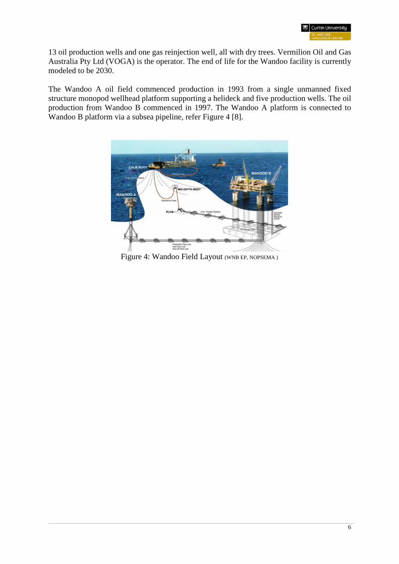
2.4.2. Wandoo B Platform
The Wandoo B platform is the first concrete gravity base production platform to be installed on Western Australia's North-West Shelf [7]. It was completed and installed in 1996. The platform is located in Carnarvon Basin, about 75km offshore in 54m of water. It consists of a CGBS supporting a two level integrated deck, refer Figure 4. The CGBS has closed cells that provide 400,000 barrels of oil storage, and open cells containing solid ballast. The platform has
6
13 oil production wells and one gas reinjection well, all with dry trees. Vermilion Oil and Gas Australia Pty Ltd (VOGA) is the operator. The end of life for the Wandoo facility is currently modeled to be 2030. The Wandoo A oil field commenced production in 1993 from a single unmanned fixed structure monopod wellhead platform supporting a helideck and five production wells. The oil production from Wandoo B commenced in 1997. The Wandoo A platform is connected to Wandoo B platform via a subsea pipeline, refer Figure 4 [8].
Figure 4: Wandoo Field Layout (WNB EP, NOPSEMA )
7
3. Concrete for Marine Structures
3.1. Introduction
Reinforced concrete structures located in marine environments such as the ocean tidal and splash zones are subject to very aggressive deteriorating actions. The concrete is the primary defensive media and requires a high level of protective measures to provide sufficient durability for the life of the concrete structure. Focused attention to durability of concrete has been due to durability-related problems in concrete structures, the main one being the corrosion of steel reinforcement. Reinforced concrete structures exposed to adverse environmental conditions undergo serious deterioration due mainly to material failures and inadequate design, construction and maintenance practices. Thus, the strength of concrete alone cannot guarantee long lasting structure. The overall durability of marine concrete structures is underpinned by strict specification requirements with durability enhancing parameters such as Supplementary Cementitious Materials (SCMs), concrete with lower water-cement ratio to offer adequate chemical and dimensional stability, in conjunction with improved construction practices and procedures for compaction, curing and cracking control. In addition, a range of other specification requirements should address various controls of source materials, chemical admixtures, and the impermeability of concrete [9].
3.2. Concrete protection
To ensure durability of concrete in marine environment, special protective measures undertaken can include [9]:
• The use of concrete containing SCMs (i.e. silica fume, fly ash, slag) at the correct replacement levels.
• Protection of all materials against chloride contamination prior to concrete placement. • Electrical continuity of the steel reinforcement for installation of CP. • Limitations to drying shrinkage and soluble salts, alkali-aggregate reactivity (AAR) and
temperature differentials across a concrete element. • Application of protective coatings in the form of silane impregnation, decorative/anti-
carbonation, anti-graffiti coatings and water tolerant epoxies in tidal zones. • Proper quality control including permeability and chloride penetration testing during
mandatory trial mixes as well as during the construction period. • Use of cathodic prevention or cathodic protection as part of the protection strategy. • As part of a long term monitoring program, mild steel and carbon macrocell/galvanic
current corrosion monitoring probes could be installed in a concrete member prior to placement of the concrete.
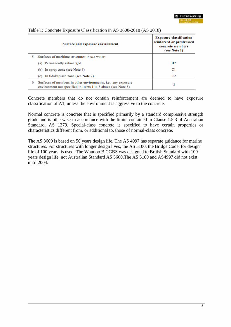
3.3. Concrete Exposure Classification and Concrete Strength
The Australian Standard, AS 3600-2018 Concrete Structures (AS 2018), stipulates the minimum requirements for the design and construction of reinforced concrete structures. The standard defines exposure classes from A to C, where A represents the most benign condition and C indicates the most severe conditions. It also includes a class 'U' representing an exposure condition for which the degree of severity is not fully known and needs proper assessment prior to specifying concrete. The AS 3600-2018 standard specifies the durability requirements for different exposure classes in terms of minimum compressive strength and types curing.
8
Table 1: Concrete Exposure Classification in AS 3600-2018 (AS 2018)
Concrete members that do not contain reinforcement are deemed to have exposure classification of A1, unless the environment is aggressive to the concrete. Normal concrete is concrete that is specified primarily by a standard compressive strength grade and is otherwise in accordance with the limits contained in Clause 1.5.3 of Australian Standard, AS 1379. Special-class concrete is specified to have certain properties or characteristics different from, or additional to, those of normal-class concrete. The AS 3600 is based on 50 years design life. The AS 4997 has separate guidance for marine structures. For structures with longer design lives, the AS 5100, the Bridge Code, for design life of 100 years, is used. The Wandoo B CGBS was designed to British Standard with 100 years design life, not Australian Standard AS 3600.The AS 5100 and AS4997 did not exist until 2004.
9
4. Deterioration of Subsea Concrete Gravity Base Structures
Concrete strength is derived from the hydration of the cement by water. The cement constituents crystalise progressively to form a paste which surrounds and binds the aggregates. The strength and permeability of concrete are generally governed by the water-cement ratio. High strength and low permeability concrete has low water-cement ratio. However, to increase the workability of concrete – placement and compaction, higher free water content is required. Water reducers (plasticisers) are used to increase workability without increasing the water/ cement ratio. Aggregate cement ratio must also be taken into account in the concrete design mix. The minimum cement content is specified to ensure the right level of alkalinity which prevents any tendency of reinforced steel to corrode [10]. Subsea concrete structures may deteriorate as a result of the combined effects of physical erosion due to wave action and floating objects, corrosion of steel reinforcement, chemical damage from sea water constituents, alkali-aggregate expansion, bacterial degradation, thermal effects, loss of pressure control, scour and foundation settlement [11]. Some of these effects are briefly discussed below.
4.1. Alkali-Aggregate Reaction
Sodium and potassium hydroxides give the concrete its alkalinity (in addition to saturated calcium hydroxide, a product of cement hydration). The concentration levels of the hydroxides depends principally on the cement source. Australian cements have low levels of hydroxides and hence low alkali levels. Most aggregates used in concrete are more or less chemically inert. However, some may contain silica which react with the alkali hydroxides in concrete, resulting in expansion and cracking of concrete over time. In this alkali-silica reaction (ASR), gels are formed and swell as they adsorb water from the surrounding cement paste or the environment. These expanding gels damage the concrete [12].
4.2. Steel Reinforcement Corrosion
For corrosion to occur, there must be at least two metals (or two locations on a single metal) at different energy levels, an electrolyte, and a metallic connection. Many separate areas of the rebar in reinforced concrete may be at different energy levels. Concrete (the pore water in concrete) acts as the electrolyte, and the metallic connection is provided by wire ties or rebar itself. During corrosion, iron atoms in the active sites (anodes) on the rebar, lose electrons and move into the surrounding concrete as ferrous ions. These loose electrons remain in the rebar and flow to cathodic sites where they combine with water and oxygen in the concrete to form hydroxyl ions which then in turn react with the ferrous ions to form iron hydroxides, or rust. The reaction products react further with dissolved oxygen leading to increased volume iron oxides. The increased volume of corrosion products results in internal stress within the concrete, which may cause cracking and spalling of the concrete cover. The alkaline environment of concrete (pH of 12 to 13) protects steel from corrosion. The high pH promotes the formation of a thin iron oxide layer on the steel and prevents metal atoms from dissolving. Of note is that this passive film does not actually stop corrosion; rather it reduces the corrosion rate to an insignificant level. The passive corrosion rate of steel in concrete is typically 0.1 µm per year. Absence of the passive film would lead to steel corrosion rates of least 1,000 times higher [13]. The passivating layer is lost when the alkalinity of the concrete becomes low or when the chloride concentration in concrete is increased to a certain level.
10
Exposure of reinforced concrete to chloride ions is a major cause of corrosion of steel reinforcement. The intrusion of chloride ions, present in seawater, into reinforced concrete can cause steel corrosion if oxygen is also available to sustain the reaction. Porous concrete or cracks in concrete can provide a pathway for chlorides dissolved in water to permeate through concrete or reach the steel through cracks. Admixtures containing chloride can also cause corrosion. Chloride ions destroy the protective oxide film on the steel, leaving the steel vulnerable to corrosion. Corrosion occurs when the chloride content at the surface of the steel exceeds a threshold limit and if water and oxygen are also available. Subsea concrete can also develop thin protective layers on its surface, mainly calcium carbonate and magnesium hydroxide, which protect the concrete surface, and hence may reduce the permeation of chlorides to the steel reinforcement. Provided there is a good depth of high quality concrete cover over the steel, reinforcement steel should normally be protected from corrosion for long periods [14]. Laboratory work has shown that the limited availability of oxygen in the underwater limits the degree of this corrosion type in subsea concrete structures [11]. However, this is not the case where macrocell corrosion occurs, i.e. small anode at a crack and/or local poor quality concrete area fuelled by a large cathode on reinforcement in uncracked/good quality concrete areas [15]. Concrete cracking allows ingress of seawater to the reinforcement steel. Most typical design basis necessitates control of cracking following the construction phase. Cracking may be limited to 0.1 mm and 0.3 mm for splash zones and submerged zones, respectively for example [16].
4.3. Chemical Attack
Naturally occurring sulfates of sodium, potassium, calcium, or magnesium are sometimes found in soil or dissolved in groundwater. The sulfates can attack concrete by reacting with hydrated compounds in the concrete. The reaction products can cause expansion of concrete, leading to cracking. Natural sea water has insufficient sulfates to cause sulfate attack. Additionally, concrete mix for offshore and subsea structures usually has some pulverised fuel ash, slag or ternary slag/silica fume or slag/flyash/silica fume in the mix to prevent any trace of sulfate attack. Carbonation occurs when carbon dioxide from the air penetrates the concrete and reacts with hydroxyl ions present in concrete to to produce carbonic acid. The carbonic acid reduces the alkalinity of the cover concrete to as low as 8.5 pH. The passive film on the steel becomes unstable at this pH level (i.e. pH < 10). This eventually leads to the steel reinforcement losing the protection of the alkaline environment; and hence the possibility of steel corrosion [17]. Subsea concrete structures do not see carbonation because they are too wet.
4.4. Bacterial degradation
The oil and water stored in subsea CGBS can be subject to sulfate reducing bacteria (SRB), resulting in production of acids. Laboratory tests have shown significant loss of concrete material when sufficiently acidic conditions exist [15]. The presence of oil-water mixtures from the operation of displacing the stored oil with seawater may present an ideal environment for SRBs. However, SRBs attack is negligible due to lack of headspace and sulphide oxidizing bacteria (SOBs) in the concrete storage tanks.

11
Additionally, the storage tanks are almost impossible to inspect due to very limited access and hence the level of damage from SRBs is difficult to assess. The thick coating that is expected to exist on the inner walls of the tanks due to the presence of waxes in the oil also acts as a barrier to SRBs attack. Drill cuttings can accumulate around the lower sections of a concrete platform or on cell roofs. These piles consist of cuttings and oil and/or water based muds. Up to the early 1980’s muds were based on diesel oil, replaced in 1984 by low toxicity oil. The presence of oil and water can encourage the development of bacteria, which are likely to be anaerobic, favoring the growth of SRBs. However, due to absence of SOBs, deterioration of the concrete material is negligible.
4.5. Fatigue
The fatigue failure occurs due to progressive propagation of flaws in steel under cyclic loading. Fatigue of steel reinforcement can occur if cyclic stresses exist in the structure. This eventually can potentially lead to cracking of the subsea structure concrete cover, which may further lead to local corrosion of steel reinforcement.
12
5. Concrete Durability Assessment Review of Wandoo B Concrete Gravity Base Structure.
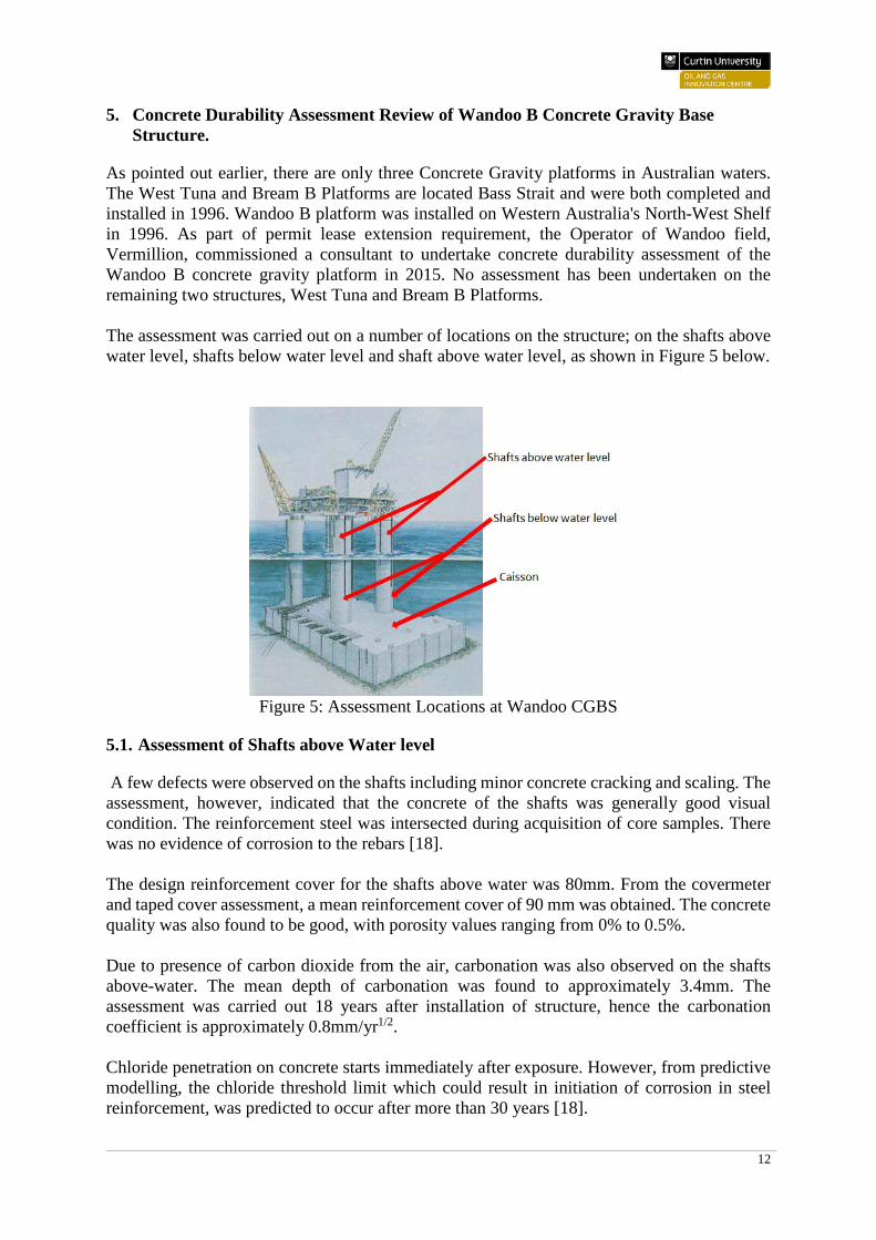
As pointed out earlier, there are only three Concrete Gravity platforms in Australian waters. The West Tuna and Bream B Platforms are located Bass Strait and were both completed and installed in 1996. Wandoo B platform was installed on Western Australia's North-West Shelf in 1996. As part of permit lease extension requirement, the Operator of Wandoo field, Vermillion, commissioned a consultant to undertake concrete durability assessment of the Wandoo B concrete gravity platform in 2015. No assessment has been undertaken on the remaining two structures, West Tuna and Bream B Platforms. The assessment was carried out on a number of locations on the structure; on the shafts above water level, shafts below water level and shaft above water level, as shown in Figure 5 below.
Figure 5: Assessment Locations at Wandoo CGBS
5.1. Assessment of Shafts above Water level
A few defects were observed on the shafts including minor concrete cracking and scaling. The assessment, however, indicated that the concrete of the shafts was generally good visual condition. The reinforcement steel was intersected during acquisition of core samples. There was no evidence of corrosion to the rebars [18]. The design reinforcement cover for the shafts above water was 80mm. From the covermeter and taped cover assessment, a mean reinforcement cover of 90 mm was obtained. The concrete quality was also found to be good, with porosity values ranging from 0% to 0.5%. Due to presence of carbon dioxide from the air, carbonation was also observed on the shafts above-water. The mean depth of carbonation was found to approximately 3.4mm. The assessment was carried out 18 years after installation of structure, hence the carbonation coefficient is approximately 0.8mm/yr1/2. Chloride penetration on concrete starts immediately after exposure. However, from predictive modelling, the chloride threshold limit which could result in initiation of corrosion in steel reinforcement, was predicted to occur after more than 30 years [18].
13
5.2. Assessment of Caisson and Shafts below Water level
There was no structural damage identified on the storage caisson and the shafts below water.
5.3. Conclusion
The corrosion of embedded steel reinforcement and pre-stressed tendons poses the most critical threat to the concrete gravity structures. The durability and long term performance of the structures is guaranteed as long as the penetration of chloride into the concrete is prevented or retarded, and all embedded steel is efficiently protected from corrosion by electrochemical passivation of highly alkaline concrete. In tidal and splash zones, plenty of oxygen is available so that high corrosion rates can take place. Crack widths of up to 0.3 mm in the concrete structure would normally not represent any corrosion problems to embedded steel in permanently immersed concrete structures [19]. In the submerged parts the shafts and caisson, availability of oxygen is generally so low that electrochemical corrosion of the embedded steel does not represent any practical problem. It may, however, be potentially be a problem at cracked locations over a design life of many decades. Additionally, there may be a variety of freely exposed metallic components in metallic connection with the embedded steel. This may represent a galvanic corrosion problem. Hence effective cathodic protection system for all freely exposed metallic components is vital to mitigate the galvanic corrosion. The assessment of Wandoo Concrete Gravity Structured was carried out in 2015, 18 years after installation of the structure. The installation was found to have good structural integrity and was fit for operation for the planned extension of 20 years. Assessment results showed no significant chemical attack on the concrete. Visual examination of the structure did not detect any sulfate attack problems.
6. Offshore Oil and Gas Assets Decommissioning Regulations
Decommissioning is the process of taking equipment or installation out of service when the maintenance and operating costs are no longer justified against the derived revenue [20].
14
6.1. International Decommissioning Legal Framework
The 1958 the Geneva Convention prescribed that all offshore installations shall be removed entirely and that the marine environment would be restored to its original condition [21]. In the 1982 United Nations Convention on the Law of the Sea (UNCLOS), oil industry representatives pointed out the tremendous costs associated with removing structures entirely from the deep sea. The representatives requested for re-examination of the complete removal requirement of the 1958 Geneva Convention. Thus, the 1982 UNCLOS gives greater flexibility to determine whether abandoned structures need to be entirely removed. The 1989 International Maritime Organization (IMO) sets out the criteria upon which to base the decisions for offshore installations removal. The IMO guidelines provide significant discretion to determine the circumstances under which abandoned offshore structures must be removed [22]. The 1989 IMO guidelines require that removal of installations is performed as soon as reasonably practicable after abandonment and it should be notified whenever a structure is not completely removed. Governments that have sovereignty of the coastal area in question may enact removal requirements that are more stringent than those called for by the IMO. The evaluation criteria of IMO guidelines to be considered by Governments during case-by-case removal determinations may include:
i. Potential effect on the safety of surface or subsurface navigation. ii. Rate and future effect of structural deterioration.
iii. Possible effect on the marine environment. iv. Potential risk that the debris will shift from its present location. v. Costs, technical feasibility and risks of injury associated with removal.
vi. Reasonable justifications for allowing structures to remain. vii. Type, draught and cargo of vessels expected to transit the area.
viii. General oceanographic and climatic conditions; and the proximity to designated or traditional sea lanes.
ix. Commercial fishing areas and straits used for international navigation. The 1989 IMO guidelines further state that any determination of the effect on the marine environment should be based on scientific evidence. Standard 3.1 of the 1989 IMO guidelines state that all abandoned installations in less than 75 meters of water and weighing less than 4,000 tons, excluding the superstructure, are to be entirely removed. However, if the structure will have a new use such as artificial reef, it may be left wholly or partially in place on the seabed. The structure may also be left in place if the government authorities are of the view that the entire removal either would not be technically feasible, would be highly costly, or would pose an unacceptable risk to personnel or the marine environment. Structures that fall outside the criteria of standard 3.1 may be left on the seabed as long as they do not cause unjustifiable interference with other uses of the sea. A monitoring plan, however, should be put in place to track the movement of structure left on the sea bed and to ensure the material do not impact negatively on navigation or other uses of the ocean. The Oslo Commission (OSCOM) guidelines of the 1972 Oslo Convention for the Disposal of Offshore Installations at Sea are consistent with and complementary to the IMO Guidelines [20]. The OSCOM guidelines require that an installation is disposed in a specific permit, a case-by-case basis disposal criteria is developed for an installation, a structure can be disposed at sea if this option is the least detrimental and all practical steps are taken to mitigate the impact of disposal on the marine environment.
15
The 1972 London Convention on the Prevention of Pollution by Dumping of Wastes and other Matter defines dumping to include specifically the disposal at sea of “platforms or other man-made structures” [23]. In the UK, the decommissioning legislations consists of three tiers; international, regional and national legislation. In each of the tiers, the regulations cover the decommissioning of installations and the disposal of waste. On the international front, the UK follow the 1982 UNCLOS. Regional decommissioning legislations and guidelines adopted by the UK include the 1972 Oslo Convention on the Prevention of Marine Pollution, the 1991 Oslo Commission (OSCOM) treaty for the for the Disposal of Offshore Platforms at Sea, the 1992 Oslo/Paris Commission (OSPAR) Convention for the Protection of the Marine Environment of the North East Atlantic and the 1993 EU Regulation 259/93 on the Supervision and Control of Shipments of Waste within, into or out of the European Community The Acts of parliament (national legislations) that govern the decommissioning in the UK continental shelf (UKCS) include the 1934 Petroleum (Production) Act, the 1949 Coast Protection Act, the 1971 Prevention of Oil Pollution Act, the 1974 Health and Safety at Work etc. Act, the 1975 The Petroleum and Submarine Pipe-lines Act, the 1982 The Oil and Gas Enterprise Act, the 1985 The Food and Environment Protection Act, the 1987 Petroleum Act, the 1990 The Environmental Protection Act, the 1993 Radioactive Substances Act and the 1998 Petroleum Act. One of the key requirements of the 1998 Act is that there needs to be full and open consultations in the decommissioning process. Hence, the decommissioning plan must be submitted to various statutory bodies.
6.2. Australia’s Decommissioning Legal Framework
Australia is a signatory to the United Nations Convention on the Law of the Sea (UNCLOS), the Convention on the Prevention of Marine Pollution by Dumping of Wastes and Other Matter (London Convention). The IMO Guidelines and Standards for the Removal of Offshore Installations and Structures on the Continental Shelf and the Exclusive Economic Zone (IMO Resolution A.672 (16)) are also applicable in Australia. All require that abandoned offshore installations and structures be removed, marine environments be protected and preserved. In Western Australia, the above requirement is subject to other provisions of “Offshore Petroleum and Greenhouse Gas Storage (OPGGS) Act 2006”, regulations and directions given by the National Offshore Petroleum Safety and Environmental Management Authority (NOPSEMA). The Commonwealth Minister may also give directions. The Offshore Petroleum Decommissioning Guidelines of 2018 is used in conjunction with OPGGS [24]. Under the OPGGS Act, the base case is to completely remove the offshore infrastructure, plug and abandon the wells. However, other options may be considered if the operator is able to demonstrate that complete removal would not be technically feasible or pose significant safety risks. Operators are expected to decommission the installations and structures before the expiry of the title.

16
17
7. Decommissioning Options
The decommissioning options should consider any potential effect on the rate of deterioration of the concrete structure, its present and possible future effect on the marine environment, the safety of navigation, or of other marine users. Other considerations include the risk that material may drift from its existing position, the cost, technical feasibility and risk of injury to personnel associated with removal of the installation or structure, the determination of a new use, or other reasonable justification for allowing the structure, or part of it, to remain subsea [25]. The decommissioning options for the concrete gravity structure platforms include:
a) Leave “as-is”. b) Partial removal- topsides removed to shore, shafts removed or toppled to achieve an
acceptable unobstructed water depth. c) Complete removal – re-floatation (remove topsides, whole substructure, plug and
abandon the wells/conductors).
7.1. Leave in Situ
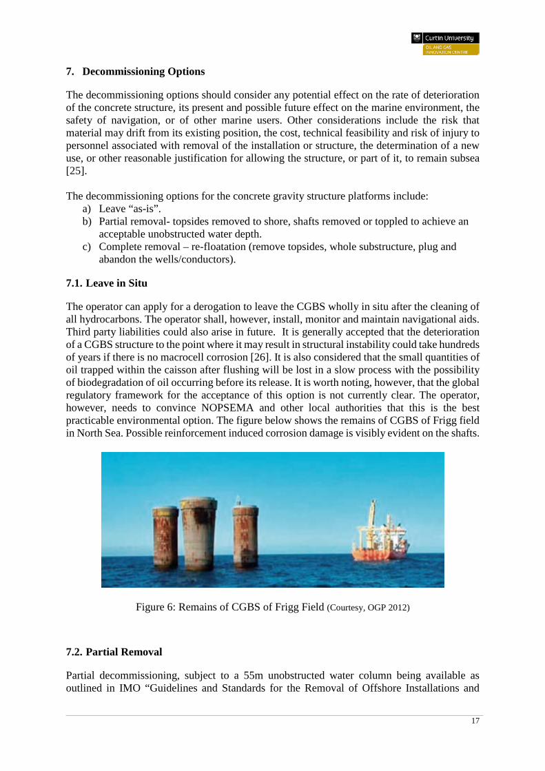
The operator can apply for a derogation to leave the CGBS wholly in situ after the cleaning of all hydrocarbons. The operator shall, however, install, monitor and maintain navigational aids. Third party liabilities could also arise in future. It is generally accepted that the deterioration of a CGBS structure to the point where it may result in structural instability could take hundreds of years if there is no macrocell corrosion [26]. It is also considered that the small quantities of oil trapped within the caisson after flushing will be lost in a slow process with the possibility of biodegradation of oil occurring before its release. It is worth noting, however, that the global regulatory framework for the acceptance of this option is not currently clear. The operator, however, needs to convince NOPSEMA and other local authorities that this is the best practicable environmental option. The figure below shows the remains of CGBS of Frigg field in North Sea. Possible reinforcement induced corrosion damage is visibly evident on the shafts.
Figure 6: Remains of CGBS of Frigg Field (Courtesy, OGP 2012)
7.2. Partial Removal
Partial decommissioning, subject to a 55m unobstructed water column being available as outlined in IMO “Guidelines and Standards for the Removal of Offshore Installations and
18
Structures on the Continental Shelf and in the Exclusive Economic Zone” of October 1989, may be considered if the Operator is able to demonstrate that complete removal would not be technically feasible or would be highly or pose an unacceptable risk to personnel or the marine environment. Partial removal of CGBS refers to removing or collapsing the shafts. The removed shafts may be either deposited on the seabed (if allowed by the government) or recovered to the surface and transported onshore. The possibility of underwater obstacles as a result of leaving the CGBS on the sea bed may create third party liabilities. This, however, shall be mitigated by marking the site on marine maps [26].
7.3. Complete Removal
The recent CGBS’s such as the Wandoo structure, have been designed with decommissioning in mind. They can be readily re-floated at the end of their productive lives. Hence removal is essentially the reversal of installation using pipework systems that have a service life well in excess of field life. These structures do not have the under-base grouting, thus making it easier to remove. Successful re-flotation is followed by onshore dismantling. The complete removal of CGBS by refloat requires the evaluation of a number of technical, cost, safety and environmental issues:
i. Continued structural integrity. ii. Accurate determination of structural weight.
iii. The ability to tow the CGBS for offshore disposal or inshore deconstruction. iv. Restoration of water-tightness and buoyancy control during refloat, towing and
deconstruction. v. Onshore dry docks or other facilities capable of accommodating and safely and
efficiently dismantling and disposing of the structure. vi. Plugging of wells/conductors.
vii. Solid ballast removal. viii. Skirt extraction.
ix. Re-use of pipework systems. x. Safety Considerations.
xi. Time and weather considerations. xii. Environmental considerations.
xiii. Cost. The feasibility of refloating, removing and demolishing any particular type of concrete substructure will have to be investigated based on its design, construction, method of installation and operational history. Any practical experience gained from previous attempts at removal of such installations has to be duly considered. Where refloating a CGBS is not possible or practical, complete removal of CGBS may also be carried out by offshore demolition. The structure is progressively deconstructed and the removed sections transported onshore or deposited on the seabed.

19
8. Risks associated with decommissioning of aging and degraded subsea concrete structures
The risks of decommissioning of aged CGBS relate to technical feasibility, cost, risk to personnel and environmental impact.
8.1. Technical feasibility
8.1.1. Structural integrity
Even though the CGBS remains fit for topside support, the “as is’ structural and watertight integrity cannot be guaranteed for refloat purposes. Unknown damage may have occurred during installation or during its operational life. There are also risks associated with maintaining the structural integrity of the concrete platform during partial or complete removal operations.
8.1.2. Jacking
Concrete Gravity Structures can weigh over 200,000 tonnes, although the Australian CGBSs are much smaller. Serious doubts exist over the capability to refloat such structures without operational risks. Key issues include how to break free of the "suction" effect (when trying to remove the caisson from the seabed). Significant jacking forces need to be generated at seabed level to release the CGBS. Insufficient jacking forces (due to small horizontal cracks leaking the pressure) may prevent separation of the structure from the seabed. The stability of the structure after release is another key issue [26].
8.1.3. Weight
During installation and throughout its working life, the weight of a CGBS may have been altered. A minor underestimate of the CGBS weight will prevent the structure lifting off the seabed. On the other hand, a slight overestimate of the weight will result in a premature and potentially uncontrolled lift off from the seabed.
8.1.4. Buoyancy
CGBSs which were not originally designed for refloating and transporting may not refloat. Moreover, the buoyancy of the structure will need to be managed and controlled over many months. Once afloat, any loss of watertight integrity could result in increased draught and the possibility of grounding, loss of stability or even total loss of the CGBS. The seabed clean up exercise after a failure of the platform during refloat or tow is likely to be a very costly and hazardous operation.
8.1.5. Time and weather
There may be limited choice or ability to select the weather window for towing a refloated CGBS to a deep water location for disposal or inshore water for demolition.
8.1.6. Mechanical cutting
For complete removal by offshore demolition, there is a risk of availability of safe and reliable cutting methods. Additionally, critical cut may not be achieved within weather window due to, e.g. diamond wire breakage/trapped blade. Thus leaving unstable CGBS sections exposed to
20
storm conditions and raising safety issues on revisiting worksite. Potential release of pre-stress energy could be a major risk to personnel. A full assessment of the safety aspects related to cutting the pre-stressed cables has yet to be evaluated [27].
8.1.7. Explosive charges
Failure to remove completely sections could leave unstable CGBS sections left exposed to storm conditions raising safety issues on revisiting worksite. The recovery of debris could also be a challenge.
8.1.8. Lifting
Concrete Gravity Based Structures weigh over 200,000 tonnes, lifting the large sections of the CGBS through the splash zone could be potentially hazardous. Lifting and transport may result in overstressing the structure if the operations are not well coordinated. There is also the issue of availability of onshore recycling facilities capable of handling the large sections and volumes of CGBS material.
8.2. Cost
It is essential to understand the costs involved in the decommissioning strategy. Currently, there is limited benchmarking data available to determine the overall decommissioning costs of CGBSs [28].
8.3. Risk to Personnel
Clean up exercise, in case of a possible total failure during refloat/towing, is likely to involve demanding subsea operations which may pose risk of injury or fatalities. Experience shows that dismantling and demolition work has a higher personnel risk than other construction work, and it may be safe to leave the wreck on the seabed [29].
8.4. Environmental and Societal impacts
The socioeconomic impacts include interference or disturbance to commercial shipping and/ or fishing. In a worst case, a failure of the refloat and towing operation, an uncontrolled diffusion of harmful compounds and release of a pile of broken concrete segments may occur. This could jeopardise ship traffic and fishing activities. Sludge in CGBS storage cells contain heavy metals and radioactive substances. This was the argument against recycling Shell’s Brent Spar, which was brought onshore, following Green Peace campaign, at huge cost to create an onshore pollution [30].
The decommissioning operations of CGBSs may result in work being undertaken at or near the seabed. Hence, there is the potential for localised long and short-term seabed disturbance. The decommissioning activities may generate underwater noise, which has the potential to impact on fish species and marine mammals. Hydrocarbons and chemicals may accidentally be released to the sea impacting on the marine environment. The likelihood of such a spill is unlikely, however.
21
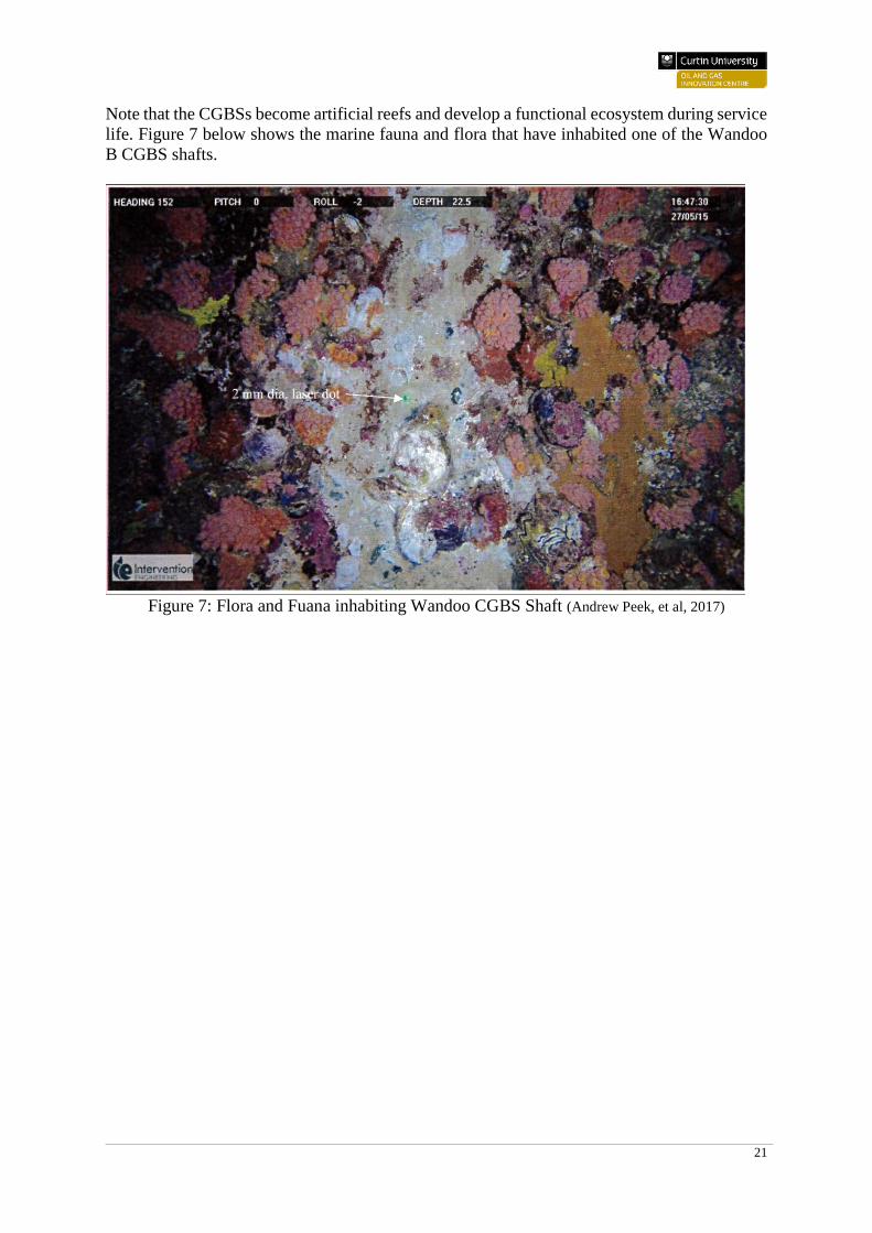
Note that the CGBSs become artificial reefs and develop a functional ecosystem during service life. Figure 7 below shows the marine fauna and flora that have inhabited one of the Wandoo B CGBS shafts.
Figure 7: Flora and Fuana inhabiting Wandoo CGBS Shaft (Andrew Peek, et al, 2017)
22
9. Conclusion
The majority of the CGBSs are installed in the OSPAR maritime region which covers the whole of the North East Atlantic area including the North Sea. Only three CGBSs are installed in Australia. The main forms of deterioration of the CGBSs include chemical deterioration, corrosion of steel reinforcement and pre-stressing tendons, bacterial degradation, scour and settlement. Carbonation-induced and chloride induced corrosion is deemed to be the most serious problem that affect the durability of marine concrete structures. Expansive corrosion products formed at the interface between concrete and reinforcing steel leads to cracking and spalling in concrete, exposing the steel to further corrosion. However, it is widely accepted that the deterioration of a CGBS to the point where it may result in structural instability could take hundreds of years. However, cracked concrete locations may potentially be a problem over a design life of many decades. The assessment of the Wandoo concrete gravity structure was carried out by an independent consultant after being in operation for 18 years. No significant defects were observed and the structure was found to be structurally sound. The United Nations Convention on the Law of the Sea (UNCLOS), the Convention on the Prevention of Marine Pollution by Dumping of Wastes and Other Matter (London Convention) and other international legal frameworks provide guidelines on decommissioning of offshore oil and gas installations and structures. Individual countries or states have also developed their own guidelines, in addition to the international guidelines which they are signatory to. The UK, for instance, has a well-developed decommissioning legal framework. The regulation development for decommissioning oil and gas installations in Australia is still at infancy stage compared to the UK. The base case for all the decommissioning regulations is to remove abandoned offshore oil and gas installations and structures, preserve and protect the marine environment. But other options may be considered if the operators are able prove that complete removal would not be feasible or pose significant safety and environment risks. Decommissioning alternatives for concrete gravity structures include reuse at existing location for non-hydrocarbon venture, assuming that the service life of the concrete structure could be extended and the topside adapted for other use; complete removal by refloat or by offshore demolition; partial removal and leave “as-is”. The criteria used in the comparative assessment of concrete gravity structures disposal option relate to:
• Environmental impact. • Safety for personnel. • Technical feasibility. • Cost.
Unlike the 2nd generation offshore concrete gravity platforms installed from the 1980s onwards, the 1st generation ones installed in the 1970s were not designed or constructed for future removal operations. The 2nd generation concrete platforms installed from the 1980s were designed and constructed with future removal capabilities. However, although the provisions for future removal were incorporated into the designs and construction of the 2nd generation CGBSs, their removal may not be fully effective because of the technical uncertainties and hazards associated with the removal, as outlined in section 9 of this report above. Hence, in determining the best decommissioning option for the concrete gravity platforms, a balance has to be struck between technical difficulty and safety, the impact on the environment and costs.

23
The leave in situ alternative may be claimed to be the best option, if considered in the short term – not several hundreds of years. The toppling over of large concrete gravity structures has never been done, hence this option will be subject to large uncertainties. Equally, the refloat/complete removal option presents considerable risks due to critical systems (ballast piping) and capabilities not being available for inspection and verification before the commencement of hazardous operations. The ballast piping may not be accessible for inspection after installation of the structure due to it being installed within the water filled concrete structure at seabed level. Extensive studies of decommissioning alternatives should be conducted and stakeholders consulted on the planned studies. All parties should be involved in the thinking process and have an open discussion of pros and cons of alternative options [31].
24
References
1. Dempsey, M., W. Mathieson, and T. Winters. Learning from offshore
decommissioning practices in Europe and the USA. in SPE Asia Pacific Oil and Gas Conference and Exhibition. 2000. Society of Petroleum Engineers.
2. Pérez Fernández, R. and M. Lamas Pardo, Offshore concrete structures. Ocean Engineering, 2013. 58: p. 304-316.
3. D.G.Gorman, J.N., Decomissioning Offshore Structures. 1997: Springer. 4. Producers, I.A.o.O.G., Disposal of disused offshore concrete gravity platforms in the
OSPAR Maritime Area. 2003. 5. Australia, E., Brean Environmental Plan Summary. 2014. 6. Titus, P., WEST TUNA I BREAM B: APPLICATION OF CONCRETE
TECHNOLOGY OFFSHORE AUSTRALIA. The APPEA Journal, 1997. 37(1): p. 546-559.
7. Humpheson, C., Foundation Design of Wandoo B Concrete Gravity Structure, in Offshore Site Investigation and Foundation Behaviour 'New Frontiers: Proceedings of an International Conference. 1998, Society of Underwater Technology: London, UK.
8. Vermillion Oil and Gas, Australia, Wandoo Facility environmental plan summary. 2017.
9. Victoria Roads, Roads, Concrete structures in marine and other saline environments. 2008.
10. Mays, G., Durability of concrete structures, investigation, repair and protection. 1992: E&FN Spon.
11. Petroleum Safety Authority, Norway, Ageing of Offshore Concrete Structures. 2009. 12. Comi, C., P. Monteiro, and R. Pignatelli, CHEMICAL AND MECHANICAL
DAMAGE IN CONCRETE DUE TO SWELLING OF ALKALI-SILICA GEL. Blucher Mechanical Engineering Proceedings, 2012. 1(1): p. 503-514.
13. American Concrete Institute, Protection of Metals in Concrete Against Corrosion. 2001.
14. Glasser, F.P., J. Marchand, and E. Samson, Durability of concrete—degradation phenomena involving detrimental chemical reactions. Cement and Concrete Research, 2008. 38(2): p. 226-246.
15. W.K Green, F.G.C., M.A Forsyth, Reinforced Concrete Corrosion, Repair and durability Brian Cherry International Concrete Symbosium, 2017.
16. Norwich, H., Offshore Technology Report. 2002. 17. Zhou, Y., et al., Carbonation-induced and chloride-induced corrosion in reinforced
concrete structures. Journal of Materials in Civil Engineering, 2014. 27(9): p. 04014245.
18. A.Peek, L.Holloway, S.Long,C O'Brien, R.Paull, Concrete durability assessment of a concrete gravity structure on australia's North West Shelf. Concrete Corrosion and Prevention, 2017.
19. Hörnlund, E., et al. Material issues in ageing and life extension. in ASME 2011 30th International Conference on Ocean, Offshore and Arctic Engineering. 2011. American Society of Mechanical Engineers.
20. Anderson, J., Decommissioning pipelines and subsea equipment: Legislative issues and decommissioning processes. Underwater Technology, 2002. 25(2): p. 105-111.
21. Gutteridge, J., The 1958 Geneva Convention on the Continental Shelf. Brit. Yb Int'l L., 1959. 35: p. 102.
25
22. McLaughlin, R.J., Coastal State Discretion, US Policy, and the New IMO Guidelines for the Disposal of Offshore Structures: Has Article 5 (5) of the 1958 Continental Shelf Convention Been Entirely Removed. Terr. Sea J., 1990. 1: p. 245.
23. de La Fayette, L., The London Convention 1972: preparing for the future. The International Journal of Marine and Coastal Law, 1998. 13(4): p. 515-536.
24. NOPTA, Offshore Petroleum Decommissioning Guideline 2018. 25. Jackson, G. and A. McNulty. Decommissioning Options for dry-built Concrete
Gravity Substructures. in Offshore Technology Conference. 1999. Offshore Technology Conference.
26. Forum, T.O.I.I.E.P., Decommissioning of Concrete Gravity Base Structures. June 1996.
27. Prasthofer, P.H. Decommissioning technology challenges. in Offshore Technology Conference. 1998. Offshore Technology Conference.
28. ABB, Offshore Oil and Gas Decommissioning. 2015. 29. Morrison, G., Decommissioning offshore concrete platforms. 2003: Atkins Process
Limited and Olav Olsen A/S 30. Ole, N. and H.P. Faga, Assessing the Impact of the Brent Spar Incident on the
Decommissioning Regime in the North East Atlantic. Hasanuddin Law Review, 2017. 3(2): p. 141-147.
31. Aven, T., J.E. Vinnem, and H. Wiencke, A decision framework for risk management, with application to the offshore oil and gas industry. Reliability Engineering & System Safety, 2007. 92(4): p. 433-448.
26
Appendices
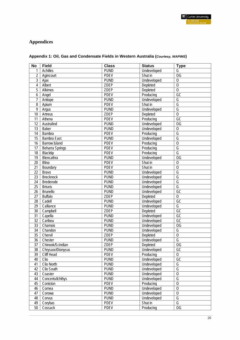
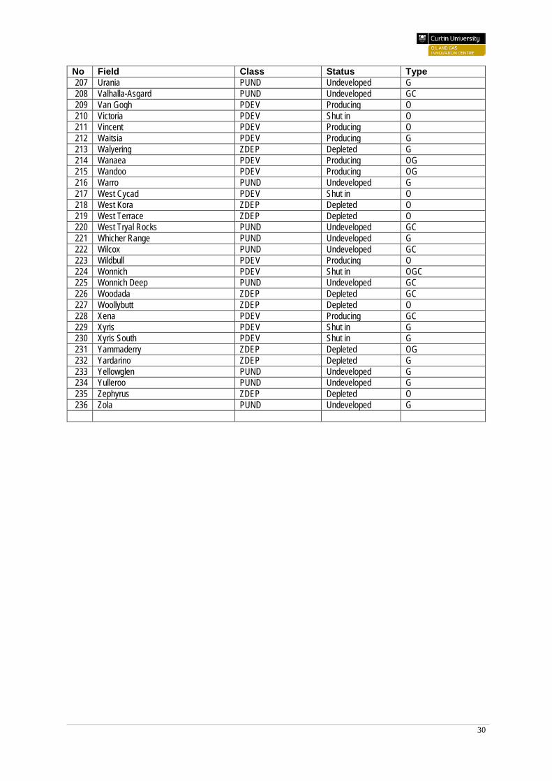
Appendix 1: Oil, Gas and Condensate Fields in Western Australia (Courtesy, WAPIMS)
No Field Class Status Type 1 Achilles PUND Undeveloped G 2 Agincourt PDEV Shut in OG 3 Ajax PUND Undeveloped O 4 Albert ZDEP Depleted O 5 Alkimos ZDEP Depleted O 6 Angel PDEV Producing GC 7 Antiope PUND Undeveloped G 8 Apium PDEV Shut in G 9 Argus PUND Undeveloped G
10 Artreus ZDEP Depleted O 11 Athena PDEV Producing GC 12 Australind PUND Undeveloped OG 13 Baker PUND Undeveloped O 14 Bambra PDEV Producing G 15 Bambra East PUND Undeveloped G 16 Barrow Island PDEV Producing O 17 Beharra Springs PDEV Producing G 18 Blacktip PDEV Producing G 19 Blencathra PUND Undeveloped OG 20 Blina PDEV Shut in O 21 Boundary PDEV Shut in O 22 Bravo PUND Undeveloped G 23 Brecknock PUND Undeveloped G 24 Brederode PUND Undeveloped G 25 Briseis PUND Undeveloped G 26 Brunello PUND Undeveloped GC 27 Buffalo ZDEP Depleted O 28 Cadell PUND Undeveloped GC 29 Calliance PUND Undeveloped G 30 Campbell ZDEP Depleted GC 31 Capella PUND Undeveloped GC 32 Caribou PUND Undeveloped GC 33 Chamois PUND Undeveloped OG 34 Chandon PUND Undeveloped G 35 Chervil ZDEP Depleted O 36 Chester PUND Undeveloped G 37 Chinook/Scindian ZDEP Depleted OG 38 Chrysaor/Dionysus PUND Undeveloped GC 39 Cliff Head PDEV Producing O 40 Clio PUND Undeveloped GC 41 Clio North PUND Undeveloped G 42 Clio South PUND Undeveloped G 43 Coaster PUND Undeveloped O 44 Concerto/Ichthys PUND Undeveloped G 45 Coniston PDEV Producing O 46 Cornea PUND Undeveloped O 47 Corowa PUND Undeveloped O 48 Corvus PUND Undeveloped G 49 Corybas PDEV Shut in G 50 Cossack PDEV Producing OG
27
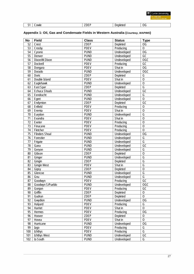
51 Cowle ZDEP Depleted OG Appendix 1: Oil, Gas and Condensate Fields in Western Australia (Courtesy, WAPIMS)
No Field Class Status Type 52 Crest ZDEP Depleted OG 53 Crosby PDEV Producing O 54 Cyrano PUND Undeveloped OG 55 Denver PUND Undeveloped GC 56 Dixon/W.Dixon PUND Undeveloped OGC 57 Dockrell PDEV Producing GC 58 Dongara PDEV Shut in OG 59 Dorado PUND Undeveloped OGC 60 Doric ZDEP Depleted G 61 Double Island PDEV Shut in O 62 Eaglehawk PUND Undeveloped O 63 East Spar ZDEP Depleted G 64 Echuca Shoals PUND Undeveloped GC 65 Eendracht PUND Undeveloped G 66 Egret PUND Undeveloped O 67 Endymion ZDEP Depleted GC 68 Enfield PDEV Producing O 69 Eremia PDEV Shut in O 70 Eurytion PUND Undeveloped G 71 Evandra PDEV Shut in O 72 Exeter PDEV Producing O 73 Finucane PDEV Producing O 74 Fletcher PDEV Producing O 75 Flinders Shoal PUND Undeveloped OG 76 Forestier PUND Undeveloped G 77 Frigate PUND Undeveloped G 78 Gaea PUND Undeveloped GC 79 Geryon PUND Undeveloped G 80 Gibson ZDEP Depleted O 81 Ginger PUND Undeveloped G 82 Gingin ZDEP Depleted G 83 Gingin West PDEV Shut in G 84 Gipsy ZDEP Depleted O 85 Glencoe PUND Undeveloped G 86 Gnu PUND Undeveloped G 87 Goodwyn PDEV Producing GC 88 Goodwyn S/Pueblo PUND Undeveloped OGC 89 Gorgon PDEV Producing GC 90 Griffin ZDEP Depleted O 91 Gudrun ZDEP Depleted O 92 Gwydion PUND Undeveloped OG 93 Halyard PDEV Producing G 94 Harriet PDEV Shut in O 95 Hermes PDEV Producing OG 96 Hoover ZDEP Depleted O 97 Hovea PDEV Shut in O 98 Hurricane PUND Undeveloped OG 99 Iago PDEV Producing G
100 Ichthys PDEV Producing G 101 Ichthys West PUND Undeveloped GC 102 Io South PUND Undeveloped G
28
Appendix 1: Oil, Gas and Condensate Fields in Western Australia (Courtesy, WAPIMS)
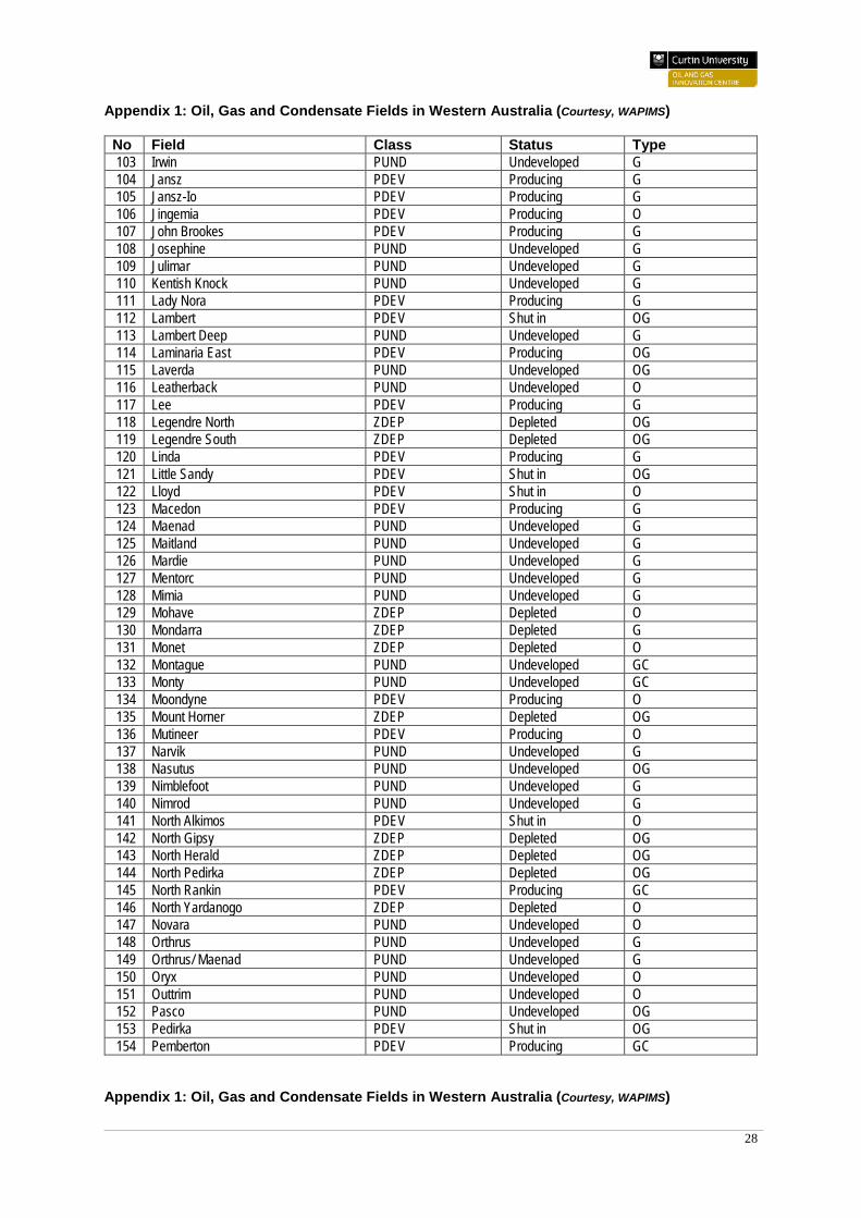
No Field Class Status Type 103 Irwin PUND Undeveloped G 104 Jansz PDEV Producing G 105 Jansz-Io PDEV Producing G 106 Jingemia PDEV Producing O 107 John Brookes PDEV Producing G 108 Josephine PUND Undeveloped G 109 Julimar PUND Undeveloped G 110 Kentish Knock PUND Undeveloped G 111 Lady Nora PDEV Producing G 112 Lambert PDEV Shut in OG 113 Lambert Deep PUND Undeveloped G 114 Laminaria East PDEV Producing OG 115 Laverda PUND Undeveloped OG 116 Leatherback PUND Undeveloped O 117 Lee PDEV Producing G 118 Legendre North ZDEP Depleted OG 119 Legendre South ZDEP Depleted OG 120 Linda PDEV Producing G 121 Little Sandy PDEV Shut in OG 122 Lloyd PDEV Shut in O 123 Macedon PDEV Producing G 124 Maenad PUND Undeveloped G 125 Maitland PUND Undeveloped G 126 Mardie PUND Undeveloped G 127 Mentorc PUND Undeveloped G 128 Mimia PUND Undeveloped G 129 Mohave ZDEP Depleted O 130 Mondarra ZDEP Depleted G 131 Monet ZDEP Depleted O 132 Montague PUND Undeveloped GC 133 Monty PUND Undeveloped GC 134 Moondyne PDEV Producing O 135 Mount Horner ZDEP Depleted OG 136 Mutineer PDEV Producing O 137 Narvik PUND Undeveloped G 138 Nasutus PUND Undeveloped OG 139 Nimblefoot PUND Undeveloped G 140 Nimrod PUND Undeveloped G 141 North Alkimos PDEV Shut in O 142 North Gipsy ZDEP Depleted OG 143 North Herald ZDEP Depleted OG 144 North Pedirka ZDEP Depleted OG 145 North Rankin PDEV Producing GC 146 North Yardanogo ZDEP Depleted O 147 Novara PUND Undeveloped O 148 Orthrus PUND Undeveloped G 149 Orthrus/ Maenad PUND Undeveloped G 150 Oryx PUND Undeveloped O 151 Outtrim PUND Undeveloped O 152 Pasco PUND Undeveloped OG 153 Pedirka PDEV Shut in OG 154 Pemberton PDEV Producing GC
Appendix 1: Oil, Gas and Condensate Fields in Western Australia (Courtesy, WAPIMS)
29
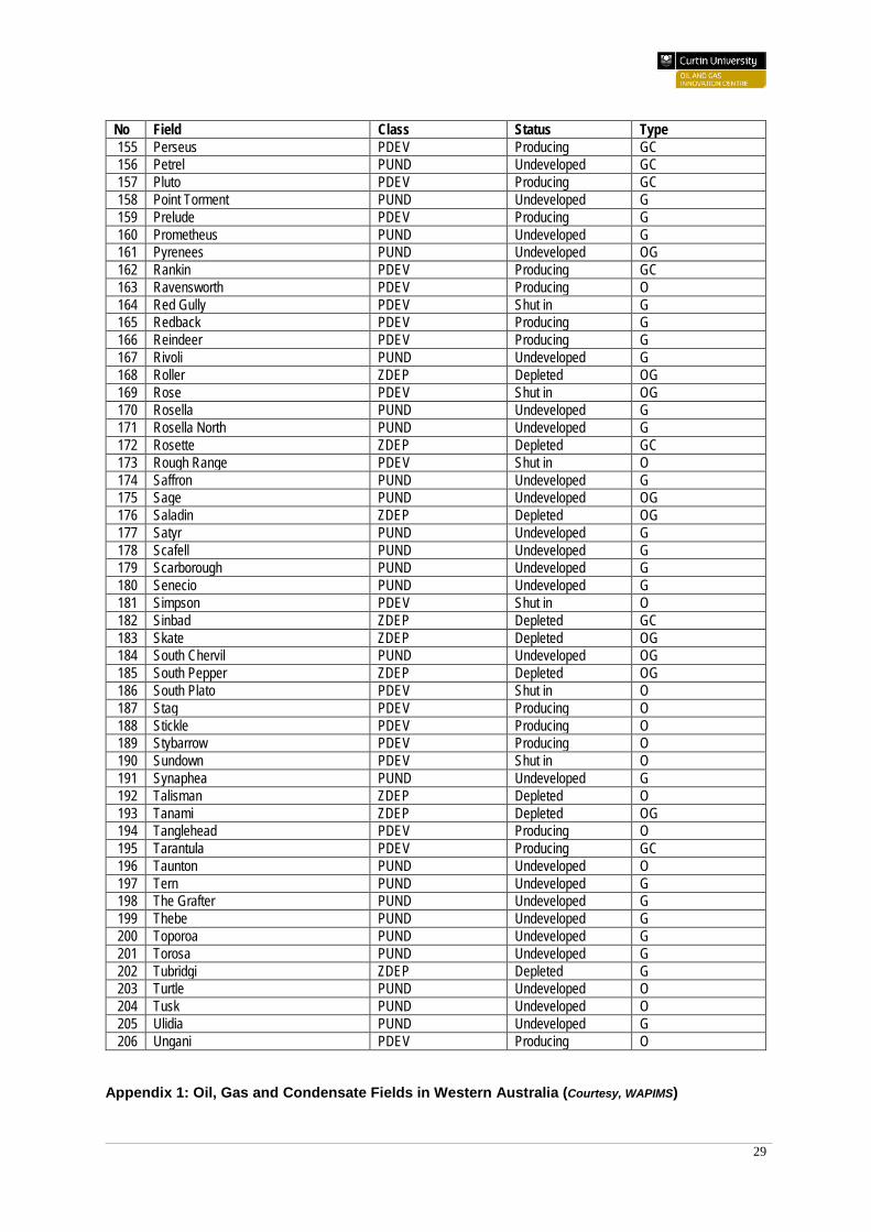
No Field Class Status Type 155 Perseus PDEV Producing GC 156 Petrel PUND Undeveloped GC 157 Pluto PDEV Producing GC 158 Point Torment PUND Undeveloped G 159 Prelude PDEV Producing G 160 Prometheus PUND Undeveloped G 161 Pyrenees PUND Undeveloped OG 162 Rankin PDEV Producing GC 163 Ravensworth PDEV Producing O 164 Red Gully PDEV Shut in G 165 Redback PDEV Producing G 166 Reindeer PDEV Producing G 167 Rivoli PUND Undeveloped G 168 Roller ZDEP Depleted OG 169 Rose PDEV Shut in OG 170 Rosella PUND Undeveloped G 171 Rosella North PUND Undeveloped G 172 Rosette ZDEP Depleted GC 173 Rough Range PDEV Shut in O 174 Saffron PUND Undeveloped G 175 Sage PUND Undeveloped OG 176 Saladin ZDEP Depleted OG 177 Satyr PUND Undeveloped G 178 Scafell PUND Undeveloped G 179 Scarborough PUND Undeveloped G 180 Senecio PUND Undeveloped G 181 Simpson PDEV Shut in O 182 Sinbad ZDEP Depleted GC 183 Skate ZDEP Depleted OG 184 South Chervil PUND Undeveloped OG 185 South Pepper ZDEP Depleted OG 186 South Plato PDEV Shut in O 187 Stag PDEV Producing O 188 Stickle PDEV Producing O 189 Stybarrow PDEV Producing O 190 Sundown PDEV Shut in O 191 Synaphea PUND Undeveloped G 192 Talisman ZDEP Depleted O 193 Tanami ZDEP Depleted OG 194 Tanglehead PDEV Producing O 195 Tarantula PDEV Producing GC 196 Taunton PUND Undeveloped O 197 Tern PUND Undeveloped G 198 The Grafter PUND Undeveloped G 199 Thebe PUND Undeveloped G 200 Toporoa PUND Undeveloped G 201 Torosa PUND Undeveloped G 202 Tubridgi ZDEP Depleted G 203 Turtle PUND Undeveloped O 204 Tusk PUND Undeveloped O 205 Ulidia PUND Undeveloped G 206 Ungani PDEV Producing O
Appendix 1: Oil, Gas and Condensate Fields in Western Australia (Courtesy, WAPIMS)
30
No Field Class Status Type 207 Urania PUND Undeveloped G 208 Valhalla-Asgard PUND Undeveloped GC 209 Van Gogh PDEV Producing O 210 Victoria PDEV Shut in O 211 Vincent PDEV Producing O 212 Waitsia PDEV Producing G 213 Walyering ZDEP Depleted G 214 Wanaea PDEV Producing OG 215 Wandoo PDEV Producing OG 216 Warro PUND Undeveloped G 217 West Cycad PDEV Shut in O 218 West Kora ZDEP Depleted O 219 West Terrace ZDEP Depleted O 220 West Tryal Rocks PUND Undeveloped GC 221 Whicher Range PUND Undeveloped G 222 Wilcox PUND Undeveloped GC 223 Wildbull PDEV Producing O 224 Wonnich PDEV Shut in OGC 225 Wonnich Deep PUND Undeveloped GC 226 Woodada ZDEP Depleted GC 227 Woollybutt ZDEP Depleted O 228 Xena PDEV Producing GC 229 Xyris PDEV Shut in G 230 Xyris South PDEV Shut in G 231 Yammaderry ZDEP Depleted OG 232 Yardarino ZDEP Depleted G 233 Yellowglen PUND Undeveloped G 234 Yulleroo PUND Undeveloped G 235 Zephyrus ZDEP Depleted O 236 Zola PUND Undeveloped G