Embed Size (px)
Citation preview
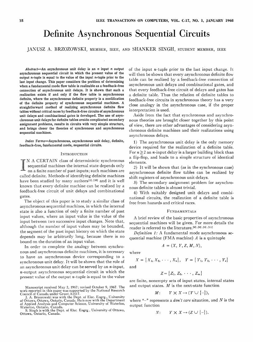
1.8 IEEE TRANSACTIONS ON COMPUTERS, VOL. C-17, NO. 1, JANUARY 1968
Definite Asynchronous Sequential CircuitsJANUSZ A. BRZOZOWSKI, MEMBER, IEEE, AND SHANKER SINGH, STUDENT MEMBER, IEEE
Abstract-An asynchronous unit delay is an n input n output of the input n-tuple prior to the last inlput change. Itasynchronous sequential circuit in which the present value of the will then be shown that every asynchronous definite flowoutput n-tuple is equal to the value of the input n-tuple prior to thelast input change. This paper considers the problem of determining ablecan brizeday a fee bac r onnetionowhen a fundamental mode flow table is realizable as a feedback-free asynchronous unit delays and combinational gates, andconnection of asynchronous unit delays. It is shown that such a that every feedback-free circuit of delays and gates hasrealization exists if and only if the flow table is asynchronous a definite table. Thus the relation of definite tables todefinite, where the asynchronous definite property is a modification feedback-free circuits in synchronous theory has a veryof the definite property of synchronous sequential machines. A close analogy in the asynchronous case, if the properstraightforward method of realizing asynchronous definite flow closetationis u se,rtables without critical races by feedback-free circuits of asynchronous interpretation is used.unit delays and combinational gates is developed. The use of asyn- Aside from the fact that synchronous and asynchro-chronous unit delays for definite tables avoids complicated secondary nous theories are brought closer together by this pointassignment problems, results in circuits with very simple structure, of view, there are other advantages of considering asyn-and brings closer the theories of synchronous and asynchronous cchronous definite machines and their realizations usingsequential machines.
asynchronous delays.Index Terms-Asynchronous, asynchronous unit delay, definite, 1) The asynchronous unit delay is the only memory
feedback-free, fundamental mode, sequential circuits. device required for the realization of a definite table.
INTRODUCTION For n > 2 an n-input delay is a larger building block thana flip-flop, and leads to a simple structure of identical
I N A CERTAIN class of deterministic synchronous elements.sequential machines the internal state depends only 2) It will be shown that (as in the synchronous case)on a finite number of past inputs; such machines are asynchronous definite flow tables can be realized by
called definite. Methods of identifying definite machines shift registers of asynchronous unit delays.have been studied by many authors['] [10] and it is well 3) The secondary assignment problem for asynchro-known that every definite machine can be realized by a nous definite tables is almost trivial.feedback-free circuit of unit delays and combinational 4) With suitably designed unit delays and combi-gates. national circuits, the realization of a definite table isThe object of this paper is to study a similar class of free from hazards and critical races.
asynchronous sequential machines, in which the internalstate is also a function of only a finite number of past FUNDAMENTALSinput values, where an input value is the value of the A brief review of the basic properties of asynchronousinput between two successive input changes. Note that, sequential machines will be given. For more details thealthough the number of input values may be bounded, reader is referred to the literature.[41['61 [81 [llthe segment of the past input history on which the state Definition 1: A fundamental mode asynchronous se-depends may be arbitrarily long, because there is no quential machine (FMA machine) A is a quintuplebound on the duration of an input value.
In order to complete the analogy between synchro- A (XI Y, Z, M, N),nious and asynchronous definite machines, it is necessary whereto have an asynchronous device corresponding to asynchronous unit delay. It will be shown that the role of X { K1, X2, * , X,, Y = { Yb Y2, 'an asynchronous unit delay can be served by an n-input, andn-output asynchronous sequential circuit in which the Z={Z1,Z2, ' * * Zm}present value of the output n-tuple is equal to the value
are finite, nonempty sets of input states, internal statesManuscript receivred May 2, 1967; revised October 9,1967. The and output states. M is the next-state function
work reported in this paper was supported by the National Research M: F>, - F -},Council of Canada under Grant A1617. M X (7 -)
J. A. Brzozowski was with the Dept. of Elec. Engrg., Universityof Ottawa, Ottawa, Ontario, Canada. He is now with the Department where "-"p represents a don't care situation, and N is theof Applied Analysis and Computer Science, University of Waterloo, uptfntoWaterloo, Ontario, Canada. ouptuntn
S. Singh is with the Dept. of Elec~Engrg., University of Ottawa, N; l ~(Z~ -)Ottawa, Ontario, Canada. XX(ZJ I
BRZOZOWSKI AND SINGH: DEFINITE ASYNCHRONOUS SEQUENTIAL CIRCUITS 19
Furthermore, Rules 1 through 5 apply to the operation states resulting from this sequence are specified exceptof the machine. possibly the last.
Before the rules of operation are given, a few defini- Definition 3: Let F1 and F2 be flow tables of FMAtions are necessary. A total state of an FMA machine is a machines. An internal state Yi of F1 is said to cover[9] anpair (Yi, Xj) where YiG Y and XjCX. A total state internal state Yj of F2 (written YiD Yj) iff, when any(Yi, Xj) is stable iff M(Yi, Xj) = Yj; otherwise it is un- input sequence applicable to Yj is applied to F1 and F2stable. A total state is a don't care state iff M(Yi, Xj) started in Yi and Yj, respectively, the outputs of F1 and""-IY. F2 are identical, whenever the output of F2 is specified.
Defnition 4: A flow table F1 coversM9' a flow tableRules of Operation F2(F1 F2) iff for each internal state Yj of F2 there is anRule 1: A must be started in a stable state. internal state Yi in F1 such that Yi2 Yj.Rule 2: The input (state) cannot change unless the If F1:F2 and if F1 has fewer internal states than F2,
present total state is stable; otherwise the input can then at least one state of F1 must cover more than onechange any time. state of F2. Whenever two states Yi and Yj of a flow
Rule 3: Let (Yis,, Xi) be the starting state, and let the table can be covered by a single state of another flowinput change from Xi. to Xj. table, then Yi and Yj must be compatible as defined
a) If M( Ys0, Xj) = Yio, the total state is again stable below.and the input can change again. Definition 5: Two internal states Yi and Yj of a flow
b) If M(Y 09 Xj)= Y, Yi and if the total state table F are compatible9] iff for any input sequence appli-(Y1, Xj) is stable, the input can change again as cable to both Yi an Yj, the output sequence which re-soon as the internal state has become Yi. sults when F is initially in Yi is the same as the output
c) If M(Yo, Xj) = Y, and if the total state (Ye, Xj) sequence which results when F is initially in Yj, when-is unstable, then the input cannot change and ever both outputs are specified. It is understood that thethe internal state of the machine becomes output sequence consists only of outputs associated
with stable total states.M(YI, Xj) = YI. This operation continues with Deiiti Theflstatesinput constant until either a stable total state Ded,n tion 6: The flow table of an FMA machine ishas been reached in a finite time and after a reduced, if notwointernalstatesof Farecompatible.finite number of changes in the internal state or It must be noted that a given table can be covered byuntil a don't care state has been reached. more than one reduced table. If there are no don't care
d) If M( Yi, Xj) = "-" further action of the machine entries, the reduced table is unique.ceases to be of interest. This is a don't care or Definition 7: An asynchronous sequential circuit is aunspecified condition. structure with p binary inputs xi, X2, .
, xi,, q binaryoutputs Z1, Z2 * , z,,, and r binary memory elements
Rule 4: After the initial input change any stable state (such as delays in feedback loops or flip-flops) with out-can be considered as a new starting state and the above puts yl, Y2, * * y8, such thatrules apply.
Rule 5: The output value is of interest only when the yi(t+A)=f;(y1(t), y2(t), * , yr(t); xl(t), x2(t), , xj,(t))total state is stable zi(t) =gj(yl(t), y2(t), * * * X yr(t); Xl(t), X2(t), * * X,(t))
Sequential machines will be represented as usual byflow tables with n columns corresponding to inputs and wherefi and gj are Boolean functions realized by combi-s rows corresponding to internal states. The entry in the national networks, yi(t+A) is the next value of yi(t),ith row and jth column consists of the pair (M( Yi, Xj), and A is the response time of the ith memory device.N(Yi, Xj)). A flow table having at most one stable state Since various specific realizations of asynchronousper row is called primitive.[4] When each unstable entry sequential circuits are adequately described in thein a flow table leads directly to a stable entry, the table literature,[4] [6] [8] [11] the above general definition willis called normal.[121 Note that every normal primitive suffice here, and the reader is referred to the literatureflow table defines an FMA machine, but the converse for more details. Every sequential circuit defines ais not generally true. However, each FMA machine can unique sequential machine, if one defines X to be set ofbe represented by a normal flow table, when multistep values of p-tuple (Xl, x2, * x,) and Y and Z are simi-transitions are replaced by one-step transitions. This is larly defined by (yi, Y2, * ** Yr~) and (z1, z2:2 **Z) andallowed since we are only interested in transitions if the M and N functions are computed from the sets ofamong stable states. Also a flow table that is not primi- Boolean functions (fi, f2, * *, fr) and (gla g2, ' *, gq),tive can be expanded to an equivalent primitive form. respectively. Note that the sequential machine defined
Definition 2: An input sequence (a sequence of values by a circuit does not have don't care entries, i.e., is fullyfrom X) is alpplicablet9l to an internal state Vt of an specified. We shall say that a circuit is a fundamentalFMA machine if,^ when the machine is placed in state mode circuit if the corresponding machine which theYA and the input sequence is applied, all the internal circuit represents is an FMA machine. A circuit is said
20 IEEE TRANSACTIONS ON COMPUTERS, JANUARY 1968
to realize an FMA machine A iff the flow table of the x xmachine defined by C covers the flow table of A.
If an asynchronous circuit is in a total state in whichthe next values of two or more internal state variables Y x Y
yi differ from the present values, the circuit is said tohave a race. If the final stable state reached as a result
(1,xiof the race depends on the order of change of the vari- Yt xiables the race is called critical.
ASYNCHRONOUS UNIT DELAY M (X,Y), Z
Definition 8: An n X n asynchronous unit delay (n X n Fig. 1. Typical transition in the general AUD.AUD) is an asynchronous sequential circuit with nbinary inputs xi, x2, , Xn and n binary outputsZ1, Z2, * zn,. At any time t the value of the output n- xi X2tuple is equal to the value of the input n-tuple at time 00 0 1 11 1 0(t-a), where (t-6) is the instant of time when the 1 i ol 4,- 7, - 10, -
input n-tuple was last changed. In symbols 20 11 4,- 7, - 10, -3 D 10 A.- 7 - 10, -
Z(t) = X(t - ) D(X(t)), 4 1, 0,oo 8, 11,-_
6 1, Q,Io 8, 11,
Z(t) (zl(t), Z2(t), . . Z , 7 2, 5,- 0 00 12, -8 2, 55,- 01o 12,
X(t) - (xI(t), X2(t), . . .Xn(t)), 9 2, - 5,- 0D10 12,
10 3, - 6, _ 9 CD, oand D denotes the delay operator. Define DO(X(t) 11 3, 6, - 9, o l01-X(t) and D(D(X(t)) =D2(X(t)) =X(t-l-a2) where 12 3, - 6, - 9, 1 11
the input changed at time (t-1-62) and (t-61), etc. Fig. 2. General 2X2 AUD.In the general case all input changes are allowed in an
AUD. However, the case where only single inputchanges are allowed will be of special interest. We shall xl X2next describe the flow tables of the two types of AUD's. 00 01 11 10
1 Qo01 3, - -, - 7, -Case 1-All Input Changes Allowed 2 Qlo 3. - -, 7,
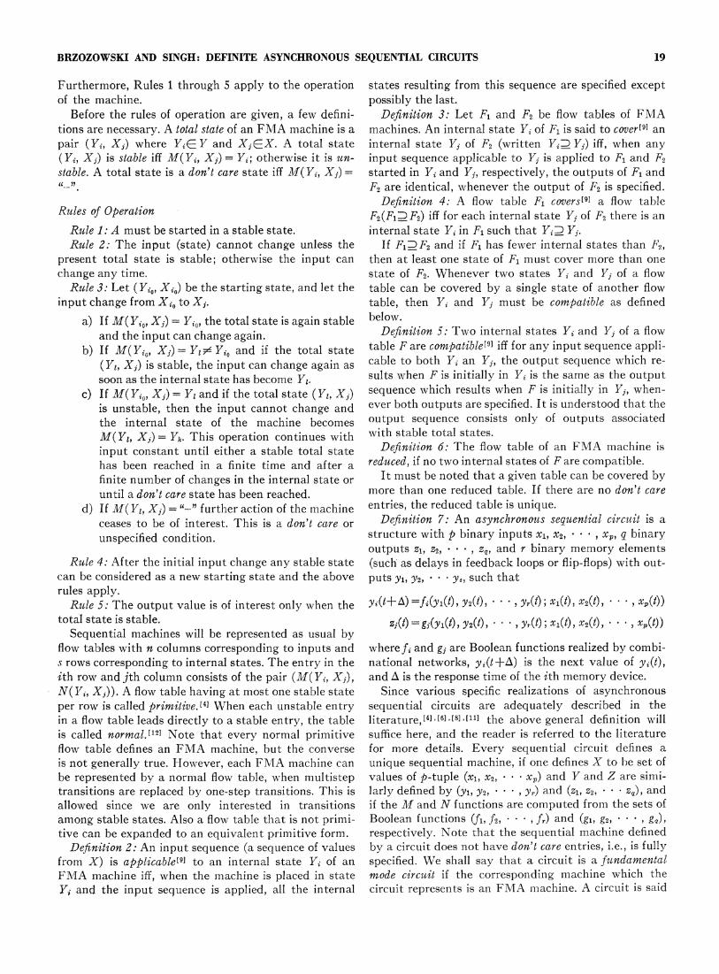
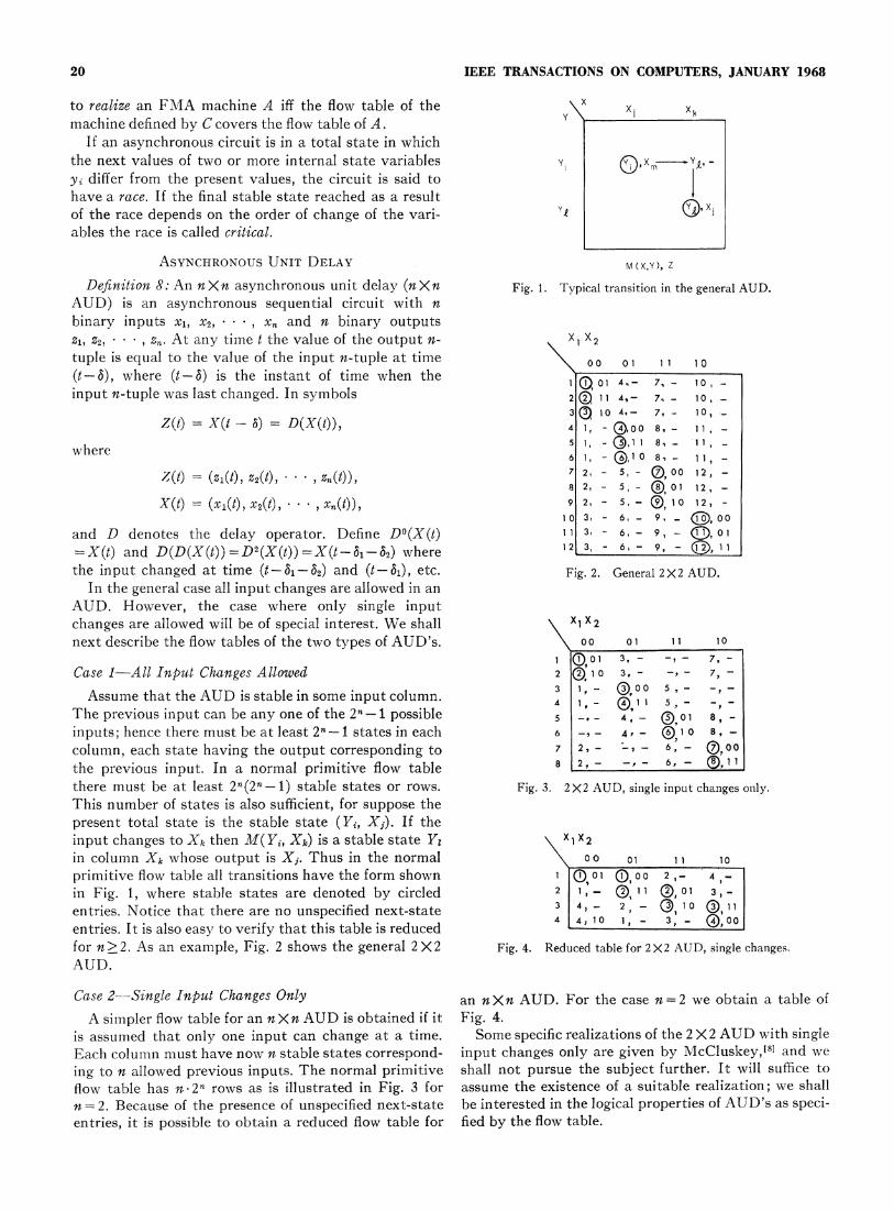
Assume that the AUD is stable in some input column. 3 1i, 8 5-The previous input can be any one of the 2n-1 possible 5 - - 4 - (D01 8, -inputs; hence there must be at least 2n -1 states in each 6 -, - 4, - (®1 0 8, -column, each state having the output corresponding to 7 2, - - 6, - D0,0the previous input. In a normal primitive flow table 8 2, - 6, - (, 11there must be at least 2n(2n-- 1) stable states or rows. Fig. 3. 2X2 AUD, single input changes only.This number of states is also sufficient, for suppose thepresent total state is the stable state (Yi, Xi). If theinput changes to Xk then M( Yi, Xk) is a stable state Y xi X2in column Xk whose output is Xj. Thus in the normal \ o 01 11 10primitive flow table all transitions have the form shown I 101 (0,00 2,- 4,-in Fig. 1, where stable states are denoted by circled 2 1- Q, 11 (0,01 3,-entries. Notice that there are no unspecified next-state 3 4, 2,2 (D,1IO 11Ientries. It is also easy to verify that this table is reduced 4 4, 1oi - 3, - 0,00for n>2. As an example, Fig. 2 shows the general 2 X2 Fig. 4. Reduced table for 2X2 AUD, single changes.AUD.
Case 2--Single InpVut Changes Only an nXn AUD. For the case n=2 we obtain a table ofA simpler flow table for an nXn AUD is obtained if it Fig. 4.
is assumed that only one input can change at a time. Some specific realizations of the 2 X2 AUD with singleEach column must have now n stable states correspond- input changes only are given by McCluskey,'5' and weing to nallowed previous inputs. The normal primitive shall not pursue the subject further. It will suffice toflow table has n-2n rows as is illustrated in Fig. 3 for assume the existence of a suitable realization; we shalln-=2. Because of the presence of unlspecified next-state be interested in the logical properties of AUD's as speci-entries, it is possible to obtain a reduced flow table for fled by the flow table.
BRZOZOWSKI AND SINGH: DEFINITE ASYNCHRONOUS SEQUENTIAL CIRCUITS 21
X 1 X2 Rule B: The tree contains a path along which a node00 01 1i 10 with more than one state appears twice.
1 0 1 1 -,-I , It is clear that the graph is always finite. Further-2 1, - (D,o -.- 3 , - more, if the graph is terminated by Rule A, F is definite,3 4- 2,- ,1 if by Rule B, it is not. It should be noted that this graph4 0,1 1 _,- 3 _ contains one more level than a similar graph drawn for
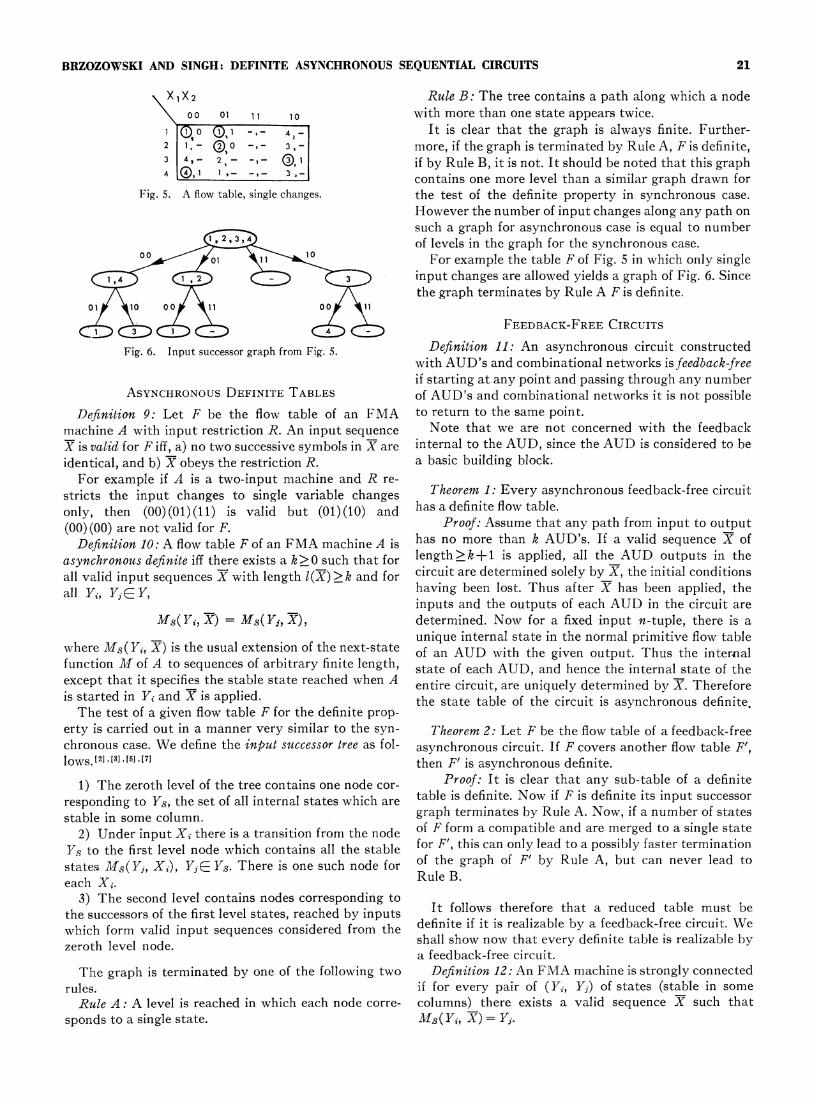
Fig. 5. A flow table, single changes. the test of the definite property in synchronous case.However the number of input changes along any path onsuch a graph for asynchronous case is equal to number
I 9 3of levels in the graph for the synchronous case.00Xol\10 For example the table F of Fig. 5 in which only single
(3 input changes are allowed yields a graph of Fig. 6. Sincethe graph terminates by Rule A F is definite.
01 s 10 00 I1 00 91
FEEDBACK-FREE CIRCUITS
Fig. 6. Input successor graph from Fig.5. Definition 11: An asynchronous circuit constructedwith AUD's and combinational networks isfeedback-freeif starting at any point and passing through any number
ASYNCHRONOUS DEFINITE TABLES of AUD's and combinational networks it is not possibleDefinition 9: Let F be the flow table of an FMA to return to the same point.
machine A with input restriction R. An input sequence Note that we are not concerned with the feedbackX is valid for F iff, a) no two successive symbols in X are internal to the AUD, since the AUD is considered to beidentical, and b) X obeys the restriction R. a basic building block.For example if A is a two-input machine and R re-
stricts the input changes to single variable changes Theorem 1: Every asynchronous feedback-free circuitonly, then (00) (01) (11) is valid but (01) (10) and has a definite flow table.(00) (00) are not valid for F. Proof: Assume that any path from input to output
Definition 10: A flow table F of an FMA machine A is has no more than k AUD's. If a valid sequenceh
ofasynchronous definite iffthere exists a k>0 such that for lengthk+ is applied, all the AUD outputs in theall valid input sequences X with length l(X).>k and for circuit are determined solely by X, the initial conditionsall Yvl Y ueYk having been lost. Thus after X has been applied, the
inputs and the outputs of each AUD in the circuit areMs(Yt, X7)= Ms(, X), determined. Now for a fixed input n-tuple, there is a
unique internal state in the normal primitive flow tablewhere Ms(Yt, X) is the usual extension of the next-state Of an AUD with the given output. Thus the internalfunction M of A to sequences of arbitrary finite length, state of each AUD, and hence the internal state of theexcept that it specifies the stable state reached when A entire circuit, are uniquely determined by X. Thereforeis started in Yi and X is applied. the state table of the circuit is asynchronous definiteThe test of a given flow table F for the definite prop-
t
erty is carried out in a manner very similar to the syn- Theorem 2: Let F be the flow table of a feedback-freechronous case. We define the input successor tree as fol- asynchronous circuit. If F covers another flow table F',lows.11 ],[3,[5,[7] then F' is asynchronous definite.
1) The zeroth level of the tree contains one node cor- Proof: It is clear that any sub-table of a definiteresponding to Ys, the set of all internal states which are table is definite. Now if F is definite its input successorstable in some column. graph terminates by Rule A. Now, if a number of states
2) Under input Xi there is a transition from the node of F form a compatible and are merged to a single stateYs to the first level node which contains all the stable for F', this can only lead to a possibly faster terminationstate.s Ms(Yj, Xi), YjC Ys. There is one such node for of the graph of F' by Rule A, but can never lead toeach Xi. Rule B.
3) The second level contains nodes corresponding tothe successors of the first level states, reached by inputs It follows therefore that a reduced table must bewhich form valid input sequences considered from the definite if it Is realizable by a feedback-free circuit. We
zeroth levelnode. ~~~~~~shall show now that every definite table is realizable bya feedback-free circuit.
The graph is terminated by one of the following two Definition 12: An FMA machine is strongly connectedrules. if for every pair of (1¾, Y1) of states (stable in someRule A: A level is reached in which each node corre- columns) there exists a valid sequence X~such that
sponds to a single state. M5(Yi, :X) = Yi.
22 IEEE TRANSACTIONS ON COMPUTERS, JANUARY 1968
Theorem 3: Every definite strongly connected flow We shall now consider the general case, in which thetable F is realizable by a shift register of AUD's and given flow table need not be strongly connected. It iscombinational logic for outputs. then possible that some states do not appear in the final
Proof: Since F is definite, its input successor tree level of the input successor tree. For example, if Yi isterminates by Rule A at some level k. Since F is strongly stable in some column, but there are no unstable Yiconnected, each internal state that is stable in some entries, then Yi can be used as a starting state. How-column must appear at least once in level k of the graph. ever, once the input changes, Yi cannot be re-entered.Assign to each appearance of Yi in level k the input We shall take care of such situations by embeddingsequence that takes the successor graph from zeroth every definite table in a strongly connected definitelevel to that appearance of Yi (Yi may be represented table.by more than one state of the AUD register). Then a Definition 13: A state Yi (stable is some input column)shift register of (k-1) AUD's realizes the state be- is a transient state if a) Yi does not appear as an un-havior of F. The ouitput can then be obtained by cornbi- stable entry of F, in which case Yi is called a primarynational circuits. transient state, or b) all appearances of Yi as unstable
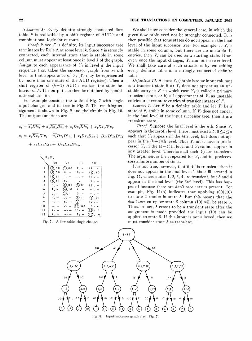
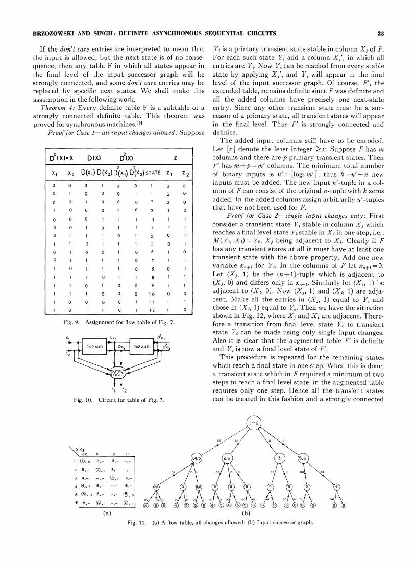
For example consider the table of Fig. 7 with single entries are next-state entries of transient states of F.input changes, and its tree in Fig. 8. The resulting as- Lemma 1: Let F be a definite table and let Yi be asignment is shown in Fig. 9 and the circuit in Fig. 10. state of F, stable in some column. If Y1 does not appearThe output functions are in the final level of the input successor tree, then it is a
transient state.Zl = x1D2x1 + x1DxbDx2 + x,Dx2D2xl + x2Dx1D2xl. Proof: Suppose the final level is the nth. Since Y1
appears in the zeroth level, there must exist a k, 0 < k < nZ x1Dx2D2X2 + x,Dx1D2xl + x,Dx,Dx2 + DxlD2xlD2x2 such that Yi appears in the kth level, but does not ap-
pear in the (k+l)th level. Thus Y1 must have a prede-± x2Dx1D.x2 -4+- Dx1Dx2D2x2. cessor Yj in the (k- 1)th level and Y1 cannot appear in
any greater level. Therefore all such Yj are transient.X 2 'Fhe argument is then repeated for Yj and its predeces-
oo 01 1 1 1 0 sors a finite number of times.I o°° ,00 9, - - It is not true, however, that if Yi is transient then it2 Qoo 6, - 10, - 10 does not appear in the final level. This is illustrated in3 ( I 1 1, - -, _ 1, - Fig. 11, where states 1, 2, 3, 4 are transient, but 3 and 44 (I1 1 6, - -, - 2, - appear in the final level (the 3rd level). This has hap-5 3, _- 01 0 0 12 - pened because there are don't care entries present. For6 1,- 0, I 1 5 _ example, Fig. 11(b) indicates that applying (00) (10)8 4, - 7, - Q1i 1 ®, 01 to state 2 results in state 3. But this means that the9 -7 - 5, - Q, I 1- don't care entry for state 5 column (10) will be state 3.
10 _, - 7, - ),0O0 8, - Thus, in fact, 3 ceases to be a transient state after theI 2, - -, 10, - ( 11 assignment is made provided the input (10) can be1 2 4-4 , 8,I - )1 04 applied to state 5. If this input is not allowed, then we
[loig. 7. A flow table, sitngle chaniges. must consider state 3 as transient.
Fig. 8.0 Inu00succso 1g0rap from Fig17
1,2,3~ ig 8.5Inu sucso rphfo i.7
BRZOZOWSKI AND SINGH: DEFINITE ASYNCHRONOUS SEQUENTIAL CIRCUITS 23
If the don't care entries are interpreted to mean that Yi is a primary transient state stable in column Xj of F.the input is allowed, but the next state is of no conse- For each such state Yi add a column Xj', in which allquence, then any table F in which all states appear in entries are Yi. Now Yi can be reached from every stablethe final level of the input successor graph will be state by applying Xj', and Y1 will appear in the finalstrongly connected, and some don't care entries may be level of the input successor graph. Of course, F', thereplaced by specific next states. We shall make this extended table, remains definite since F was definite andassumption in the following work. all the added columns have precisely one next-state
Theorem 4: Every definite table F is a subtable of a entry. Since any other transient state miiust be a suc-strongly connected definite table. This theoreiii was cessor of a primary state, all transient states will appearproved for synchronous machines.[3] in the final level. Thus F' is strongly connected and
Prooffor Case 1-all input changes allowed: Suppose definite.The added input columns still have to be encoded.
Let [x] denote the least integer >x. Suppose F has mD (X):x D(X) D(X) z columns and there are p primary transient states. Then
2 2 F' has m+p=m' columns. The minimum total numberxI X2 D(x1) D(x2)D(x1) D(X2)STATE Z, Z2 of binary inputs is n'= [log2 m']; thus k=n'-n new
o o o O o o oinputs must be added. TFhe new input n'-tuple in a col-o 1l~ ~ 0 o umn of F can consist of the original n-tuple with k zeroso o 0 l 2oo added. In the added columns assign arbitrarily n'-tuples1 0 0 0 1 O 2 1 0 that have not been used for F.o 0 0 1 1 3 1 1 Proof for Case 2-single input changes only: Firsto 0 0 1 4 1 1 consider a transient state Yi stable in column Xj whicho 1 1 0 5 0 1 reaches a final level state Yk stable in Xi in one step, i.e.,1 1 0 1 1 1 5 0 1 M(Yi, XI) = Yk, Xj being adjacent to Xi. Clearly if F0 1 0 0 1 0 6 1 0 has any transient states at all it must have at least one0 1 1 1 0 7 1 1 transient state with the above property. Add one new1 0 1 1 1 0 8 ° variable x,+ for Yi. In the columns of F let Xn1=0.1 1 0 1 1 8 1 1 Let (Xj, 1) be the (n+1)-tuple which is adjacent to1 1 a 1 0 0 9 1 1 (Xj, 0) and differs only in xnil. Similarly let (Xi, 1) be
1 0o o 1o 0l adjacent to (Xi, 0). Now (Xj, 1) and (XI, 1) are adja-0 0 0 0 1 1 1 1 1 cent. Make all the entries in (Xj, 1) equal to Yi and
1 0 1 1 0 1 12 0 those in (Xi, 1) equal to Yk. Then we have the situationshown in Fig. 12, where Xj and XI are adjacent. There-
Fig. 9. Assignment for flow table of Fig. 7. fore a transition from final level state Yk to transientstate Yi can be made using only single input changes.
x_ r ^ ; 1Also it is clear that the augmented table F' is definite2x2AUD DX2 2x2AUD Dx2 and Yi is now a final level state of F'.
2 > This procedure is repeated for the remaining statesif C which reach a final state in one step. When this is done,
a transient state which in F required a minimum of twosteps to reach a final level state, in the augmented table
zi 7Z requires only one step. Hence all the transient states'Fig. 10. Circuit for table of Fig. 7. can be treated in this fashion and a strongly connected
x1x2 i
2 5,- 2,- 3- ,- o/\l oJlX o 1 o3 4.- -,- ®a,r 5.-/ / \ \
S~~~~~~~~~0 0fi oI 00 -I 00 01 01 oI 00 II 00Al 01o 01AWl 00Ro0101ooII 00 H16~~~~''5,36tX () 4 5 56 6 54 55 6 6 6 56 5
X6
(a) (b)Fig. 11. (a) A flow table, all changes allowed. (b) Inlput successor graph.
24 IEEE TRANSACTIONS ON COMPUTERS, JANUARY 1968
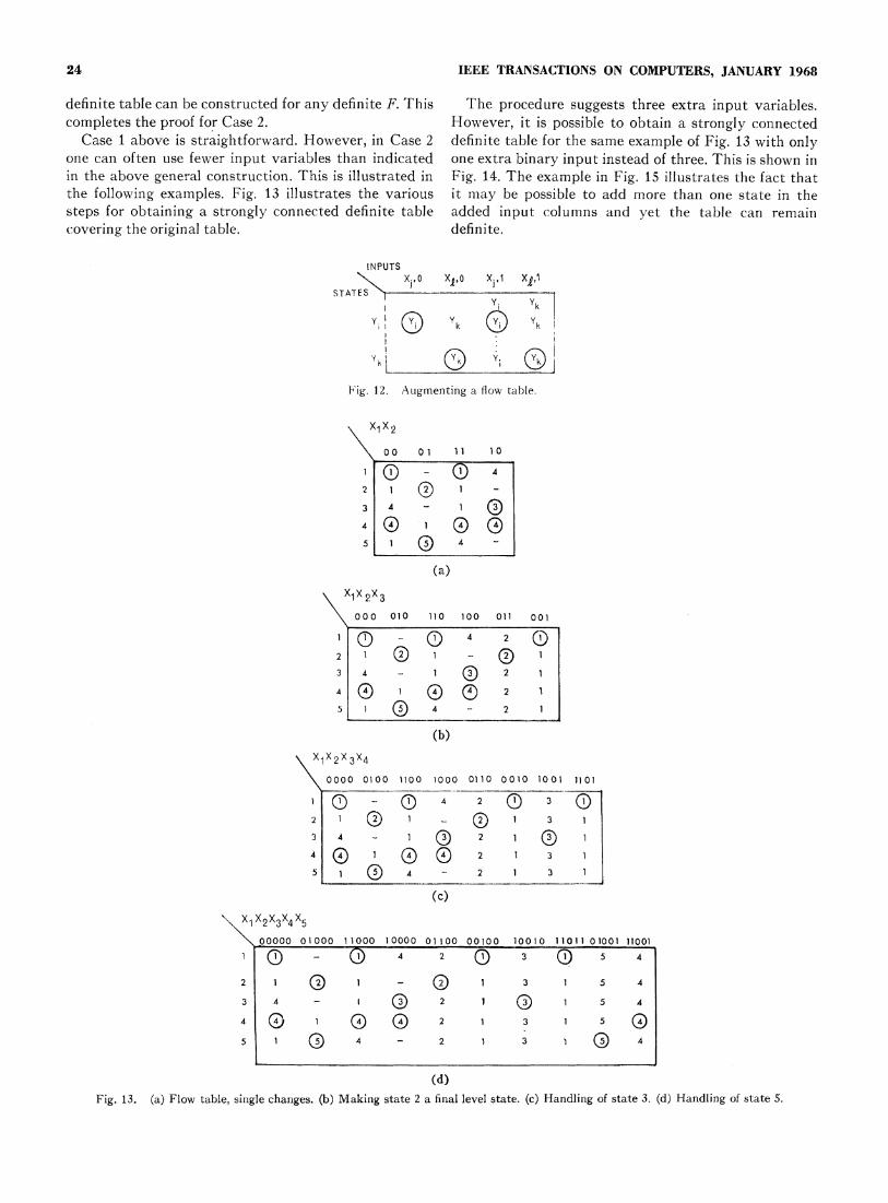
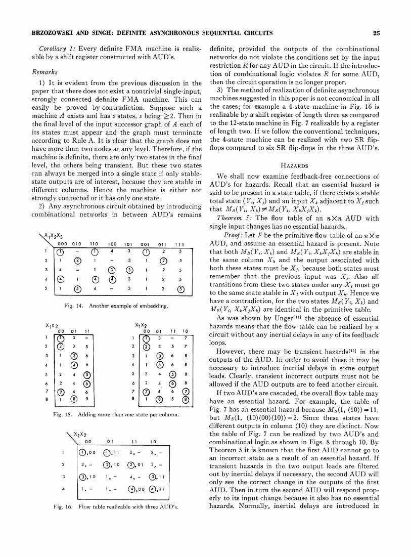
definite table can be constructed for any definite F. This The procedure suggests three extra input variables.completes the proof for Case 2. However, it is possible to obtain a strongly connected
Case 1 above is straightforward. However, in Case 2 definite table for the same example of Fig. 13 with onlyone can often use fewer input variables than indicated one extra binary input instead of three. This is shown inin the above general construction. This is illustrated in Fig. 14. The example in Fig. 15 illustrates the fact thatthe following examples. Fig. 13 illustrates the various it may be possible to add more than one state in thesteps for obtaining a strongly coninected definite table added input columnrs and yet the table can remaincovering the original table. definite.
INPUTS\Xj, O XpO0 Xi ,1 XPA
STATES
k) Q ~k k
Fig. 12. Augmentirng a flow table.
X1X2
00 01 11 10
2 1 1 -
3 4 - Q
40105 1 0 4
(a)X1X 2X3
000 010 110 100 011 001
1 Q Q 4 2 Q
2 1 - Q
3 4 - 1 2 1
4 01 215 1 0 4 2 1
(b)X1X2X3X4
0000 0100 1100 1000 0110 0010 1001 1lO1
10-0_ 4 2Q 32 1 0 0 1 3 1
3 4 0 2 1 0 1
0 1 0 2 1 3 1
5 1 0 4 2 1 3 1
(c)X XX2x3x4x
00000 01000 11000 10000 01100 00100 10010 11011 01001 110011O _ (j) ~~~~~42 3 5 4
2 ~1J 0 2- @ 1 3 1 5 0
(d)
Fig. 13. (a) Flow table, single chanlges. (b) Making state 2 a final level state. (c) :Hanldlinlg of state 3. (d) Handling of state 3.
BRZOZOWSKI AND SINGH: DEFINITE ASYNCHRONOUS SEQUENTIAL CIRCUITS 25
Corollary 1: Every definite FMA machine is realiz- definite, provided the outputs of the combinationalable by a shift register constructed with AUD's. networks do not violate the conditions set by the input
restriction R for any AUD in the circuit. If the introduc-Remarks tion of combinational logic violates R for some AUD,
1) It is evident from the previous discussion in the then the circuit operation is no longer proper.paper that there does not exist a nontrivial single-input, 3) The method of realization of definite asynchronousstrongly connected definite FMA machine. This can machines suggested in this paper is not economical in alleasily be proved by contradiction. Suppose such a the cases; for example a 4-state machine in Fig. 16 ismachine A exists and has s states, s being > 2. Then in realizable by a shift register of length three as compared.the final level of the input successor graph of A each of to the 12-state machine in Fig. 7 realizable by a registerits states must appear and the graph must terminate of length two. If we follow the conventional techniques,according to Rule A. It is clear that the graph does not the 4-state machine can be realized with two SR flip-have more than two nodes at any level. Therefore, if the flops compared to six SR flip-flops in the three AUD's.machine is definite, there are only two states in the finallevel, the others being transient. But these two states HAZARDScan always be merged into a single state if only stable- We shall now examine feedback-free connections ofstate outputs are of interest, because they are stable in AUD's for hazards. Recall that an essential hazard isdifferent columns. Hence the machine is either not said to be present in a state table, if there exists a stablestrongly connected or it has only one state. total state (Y¾, Xj) and an input Xk adjacent to Xj such
2) Any asynchronous circuit obtained by introducing that Ms(Yi, Xk) FMS(Yi, XkXjXk).combinational networks in between AUD's remains Theorem 5: The flow table of an nXn AUD with
single input changes has no essential hazards.x1x2x3 Proof: Let F be the primitive flow table of an n Xn
000 010 110 100 101 001 011 111 AUD, and assume an essential hazard is present. Note1 - 4 3 2 5 that both MS(Yi, Xk) and MS(Yi, XkXjXk) are stable in2 1 1 - 3 (D 5 the same column Xk and the output associated with3 4 - 1 q 1 2 5 both these states must be Xj, because both states must4 0C 1 @ s 3 1 2 5 remember that the previous input was Xj. Also all5 1 1 D A
4 - 3 2 (!) transitions from these two states under any XI must go. ~~~~~~tothe same state stable in Xi with output Xk. Hence we
have a contradiction, for the two states MS(Yi, Xk) andFg1AnheapoemdnMs(Y, XkXjXk) are identical in the primitive table.
As was shown by Unger["l] the absence of essentialX1x2 X1X2 hazards means that the flow table can be realized by a
00 01 11 0o0 01 11 1 0 circuit without any inertial delays in any of its feedback1 Q 3 - loops.2 3 5 2 3 5 7
lo s
3 1 0 6 3 1 6 8 However, there may be transient hazards["1] in theoutputs of the AUD. In order to avoid these it may be06 41 necessary to introduce inertial delays in some output
5 2 4 5 2 4 Q 8 leads. Clearly, transient incorrect outputs must not be6 2 4 0 6 2 4 ® 8 allowed if the AUD outputs are to feed another circuit.7 0 4 6 7 0 A 6 0 If two AUD's are cascaded, the overall flow table may8 0 1 0 5 have an essential hazard. For example, the table of
Fig. 7 has an essential hazard because Ms(t, (10))= 11,Fig. 15. Adding more than one statepercolumn. but Ms(l, (10)(00)(10))=2. Since these states have
different outputs in column (10) they are distinct. Nowx x2 the table of Fig. 7 can be realized by two AUD's and
000o 1 1 1 1 0 combinational logic as shown in Figs. 8 through 10. By1 0,00 0,11l 2, _ 3, Theorem 5it is known that the first AUD cannot go to
an incorrect state as a result of an essential hazard. If2 3,- Q2,10 Q!,01 3, - transient hazards in the two output leads are filtered3 |()] 1- 4,- )1|out by inertial delays if necessary, the second AUD will1. , 4Q . only see the correct change in the outputs of the first4 1, - 1, 0,@00 0,01 AUD. Then in turn the second AUD will respond prop-
. ~~~~~~~~erlyto its input change because it also has no essentialFig. 16. Flow table realizable with three AUD's. hazards. Normally, inertial delays are introduced in
26 IEEE TRANSACTIONS ON COMPUTERS, JANUARY 1968
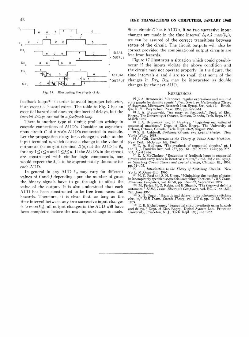
x, v1 Since circuit C has k AUD's, if no two successive input
1 changes are made in the time interval At<k max(aij),2 =,2 ... 2 .i''Nwe can be assured of the correct transitions between
x2 0 states of the circuit. The circuit outputs will also beDx 1 I correct provided the combinational output circuits are- -° ° 0 ~~~~~~~0 1 ID EAL
1-J1l OUTPUT free from hazards.Dx 0 0 O Figure 17 illustrates a situation which could possibly2 occur if the inputs violate the above condition and
Dx 1 1 the circuit may not operate properly. In the figure, thel18 to 0 =0 ACTUAL time intervals a and b are so small that some of the
1 t4t + i * SOUTPUT changes in Dxl, Dx2 may be interpreted as doubleDx2 0 IJ changes by the next AUD.
Fig. 17. Illustrating the effects of Si. REFERENCES
[1] J. A. Brzozowski, "Canonical regular expressions and minimalfeedback loops[11] in order to avoid improper behavior, state graphs for definite events," Proc. Symp. on Mathematical Theoryif an essential hazard exists. The table to Fig. 7 has an of Automata, Microwave Research Inst. Symp. Ser., vol. 12. Brook-
lyn, N. Y.: Polytechnic Press, 1962, pp. 529-561.essential hazard and does require inertial delays, but the [2] J. A. Brzozowski, "An essay on feedback," Dept. of Elec.inertial delays are not in a feedback loop. Engrg., The University of Ottawa, Ottawa, Canada, Tech. Rept. 65-2,
March 1965.There is another type of timing problem arising in [3] J. A. Brzozowski and P. Hawtrey, "Logic-free realization of
cascade connections of AUD's. Consider an asynchro- sequential machines," Dept. of Elec. Engrg., The University ofOttawa, Ottawa, Canada, Tech. Rept. 66-9, August 1966.
nous circuit C of k nXn AUD's connected in cascade. 14] S. H. Caldwell, Switching Circuits and Logical Design. NewLet the propagation delay for a change of value at the York: Wiley, 1958.16] A. Gill, Introduction to the Theory of Finite State Machines.input terminal xi which causes a change in the value of New York: McGraw-Hill, 1962.output at the output terminal D(xj) of the AUD be af [6a D. A. Huffman, "The synthesis of sequential circuits," pt. I
and II, J. Franklin Inst., vol. 257, pp. 161-190, March 1954; pp. 275-for any 1 < i < n and 1 <j < n. If the AUD's in the circuit 303, April 1964.are constructed with similar logic components, one 17] E. J. McCluskey, "Reduction of feedback loops in sequentialcircuits and carry leads in iterative circuits," Proc. 3rd Ann. Symp.would expect the bij s to be approximately the same for on Switching Circuit Theory and Logical Design, Chicago, Ill., 1962,each AUD. pp. 91102.
181 , Introduction to the Theory of Switching Circuits. NewIn general, in any AUD bij may vary for different York: McGraw-Hill, 1965.
values of i and j depending upon the number of gates 9] M. C. Paul and S. H. Unger, "Minimizing the number of statesin incompletely specified sequential switching functions," IRE Trans.
the binary signals have to go through to affect the Electronic Computers, vol. EC-8, pp. 356-367, September 1959.value of the output. It is also understood that each [I'] M. Perles, M. 0. Rabin, and E. Shamir, "The theory of definiteautomata," IEEE Trans. Electronic Computers, vol. EC-12, pp. 233-AUD has been constructed to be free from races and 243, June 1963.hazards. Therefore, it is clear that, as long as the I'l] S. H. Unger, "Hazards and delays in asynchronous switchingcircuits," IRE Trans. Circuit Theory, vol. CT-6, pp. 12-25, Marchtime interval between any two successive input changes 1959.is > max(aij), all output changes in the AUD will have [121 E. B. Eichelberger, "Sequential circuit synthesis using hazards
and delays," Dept. of Elec. Engrg., Digital System Lab., Princetonbeen completed before the next input change is made. University, Princeton, N. J., Tech. Rept. 19; June 1962.