Embed Size (px)
Citation preview
9/10/12
1
Sequential Logic (2)
ENGG1015 1st Semester, 2012
Dr. Hayden So
Department of Electrical and
Electronic Engineering
http://www.eee.hku.hk/~engg1015
Synchronous vs Asynchronous Sequential Circuit
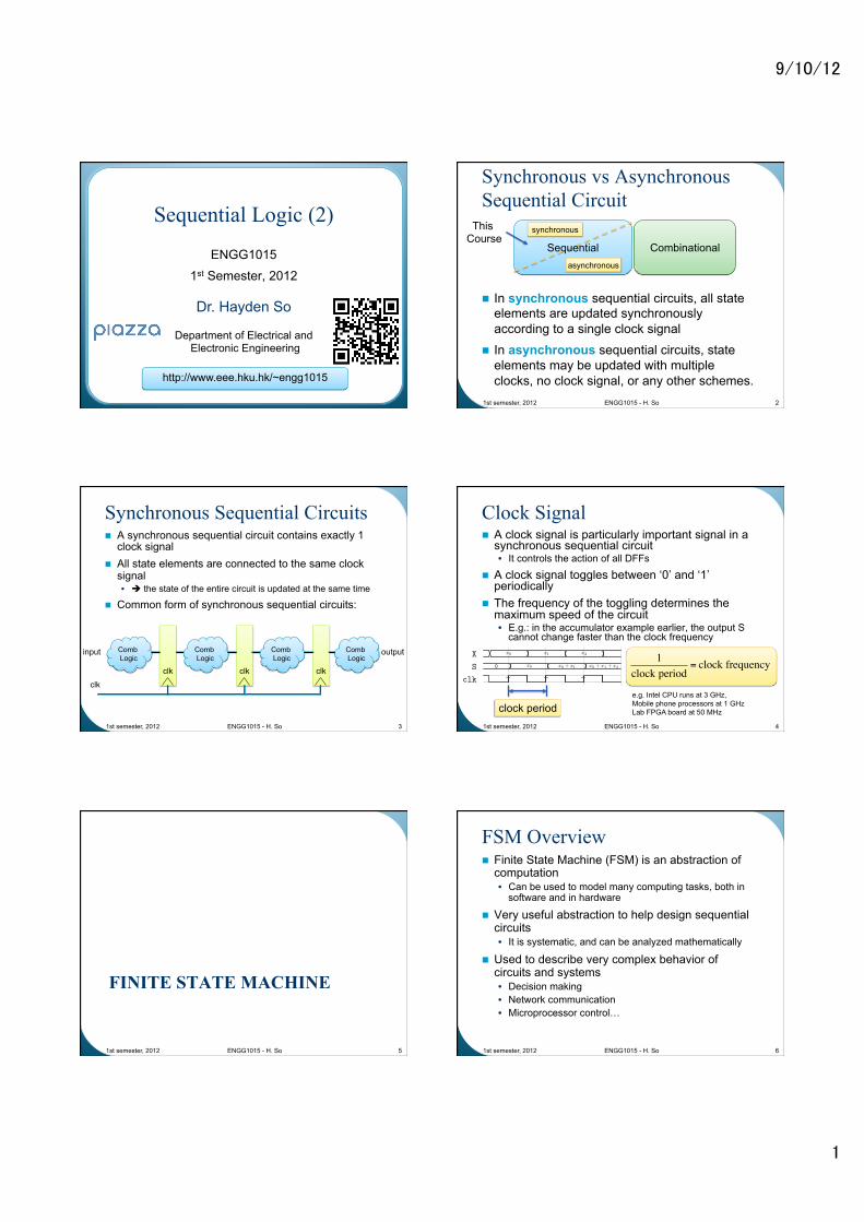
n In synchronous sequential circuits, all state elements are updated synchronously according to a single clock signal
n In asynchronous sequential circuits, state elements may be updated with multiple clocks, no clock signal, or any other schemes.
1st semester, 2012 ENGG1015 - H. So 2
Combinational
synchronous
asynchronous
Sequential
This Course
Synchronous Sequential Circuits n A synchronous sequential circuit contains exactly 1
clock signal n All state elements are connected to the same clock
signal • è the state of the entire circuit is updated at the same time
n Common form of synchronous sequential circuits:
1st semester, 2012 ENGG1015 - H. So 3
clk
Comb Logic
clk
input
clk
Comb Logic
clk
Comb Logic
Comb Logic
output
Clock Signal n A clock signal is particularly important signal in a
synchronous sequential circuit • It controls the action of all DFFs
n A clock signal toggles between ‘0’ and ‘1’ periodically
n The frequency of the toggling determines the maximum speed of the circuit • E.g.: in the accumulator example earlier, the output S
cannot change faster than the clock frequency
1st semester, 2012 ENGG1015 - H. So 4
X x0 x1 x2
S 0 x0 x0 + x1 x0 + x1 + x2
clk
1
clock period
1clock period
= clock frequency
e.g. Intel CPU runs at 3 GHz, Mobile phone processors at 1 GHz Lab FPGA board at 50 MHz
FINITE STATE MACHINE
1st semester, 2012 ENGG1015 - H. So 5
FSM Overview n Finite State Machine (FSM) is an abstraction of
computation • Can be used to model many computing tasks, both in
software and in hardware
n Very useful abstraction to help design sequential circuits • It is systematic, and can be analyzed mathematically
n Used to describe very complex behavior of circuits and systems • Decision making • Network communication • Microprocessor control…
1st semester, 2012 ENGG1015 - H. So 6
9/10/12
2
Defining Finite State Machines n Each FSM defines:
• Finite number of states that the machine can be in • The conditions under which it will transition from
one state to another
n At any moment in time, an FSM can only exist in 1 of the defined states
n The output of an FSM depends on the state that the FSM • Optionally depend on the input to the FSM
1st semester, 2012 ENGG1015 - H. So 7
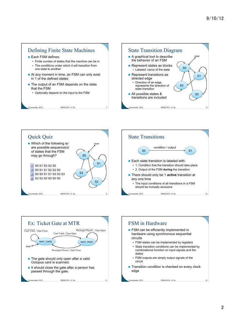
State Transition Diagram n A graphical tool to describe
the behavior of an FSM n Represent states as blocks
• Labeled: name of the state
n Represent transitions as directed edge • Direction of an edge
represents the direction of state transition
n All possible states & transitions are included
1st semester, 2012 ENGG1015 - H. So 8
S0
S1
S3
S2
reset
Quick Quiz n Which of the following is/
are possible sequence(s) of states that the FSM may go through?
• S0 S1 S3 S2 S0 • S0 S1 S1 S2 S2 S0 • S0 S0 S1 S1 S3 S3 S3 • S2 S2 S0 S0 S0 S0
1st semester, 2012 ENGG1015 - H. So 9
S0
S1
S3
S2
reset
1
2
3
4
State Transitions
n Each state transition is labeled with: • 1. Condition that the transition should take place • 2. Output of the FSM during the transition
n There should only be 1 active transition at any one time • The input conditions of all transitions in a FSM
should be mutually exclusive
1st semester, 2012 ENGG1015 - H. So 10
S0 S1 condition / output
Ex: Ticket Gate at MTR
n The gate should only open after a valid Octopus card is scanned.
n It should close the gate after a person has passed through the gate.
1st semester, 2012 ENGG1015 - H. So 11
WAIT_CARD WAIT_PASS
reset
Card Valid Gate CloseCard Valid Gate Open
Passenger Passed Gate Open
Passenger Passed Gate Close
FSM in Hardware n FSM can be efficiently implemented in
hardware using synchronous sequential circuits • FSM states can be implemented by registers • State transition conditions can be implemented by
combinational function on input signals and the states
• FSM outputs are simply output signals of the circuit
n Transition condition is checked on every clock edge
1st semester, 2012 ENGG1015 - H. So 12
9/10/12
3
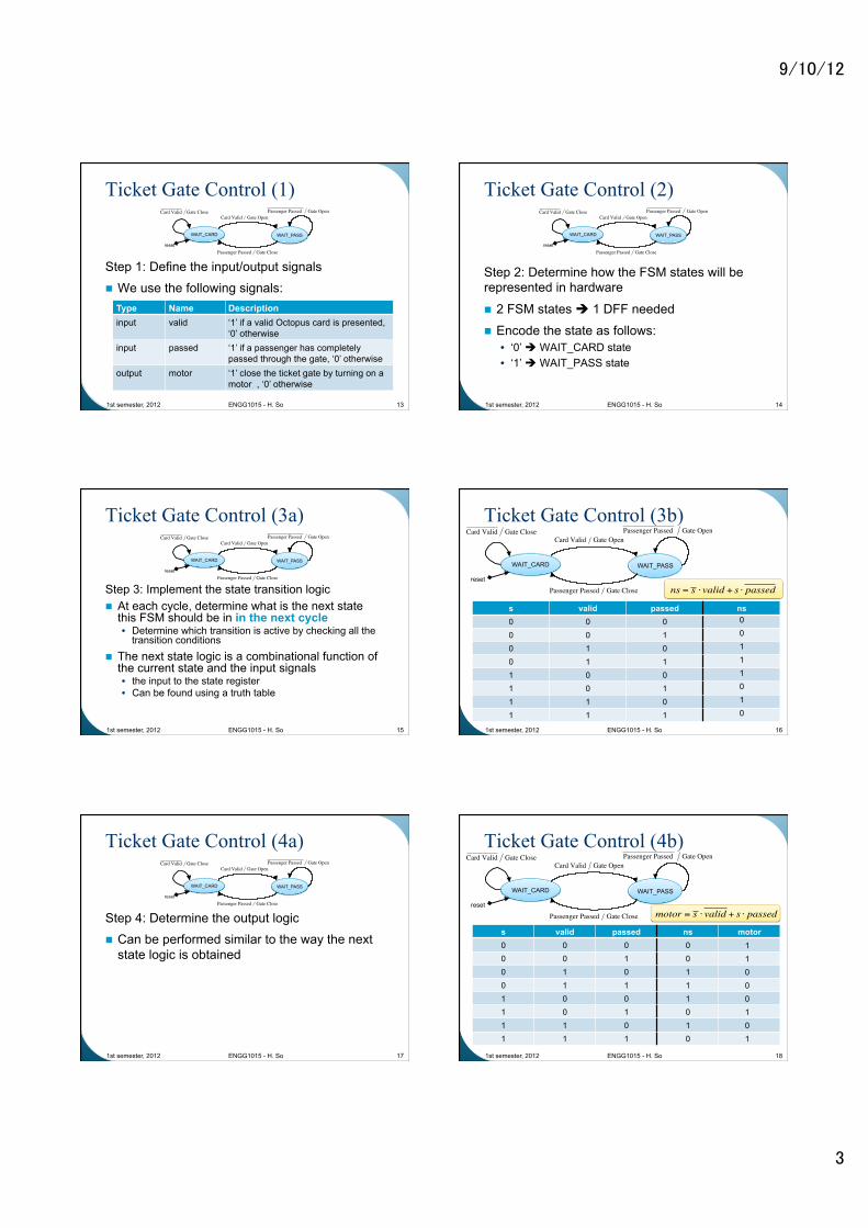
Ticket Gate Control (1)
Step 1: Define the input/output signals n We use the following signals:
1st semester, 2012 ENGG1015 - H. So 13
WAIT_CARD WAIT_PASS
reset
Card Valid Gate CloseCard Valid Gate Open
Passenger Passed Gate Open
Passenger Passed Gate Close
Type Name Description input valid ‘1’ if a valid Octopus card is presented,
‘0’ otherwise input passed ‘1’ if a passenger has completely
passed through the gate, ‘0’ otherwise output motor ‘1’ close the ticket gate by turning on a
motor , ‘0’ otherwise
Ticket Gate Control (2)
Step 2: Determine how the FSM states will be represented in hardware
n 2 FSM states è 1 DFF needed
n Encode the state as follows: • ‘0’ è WAIT_CARD state • ‘1’ è WAIT_PASS state
1st semester, 2012 ENGG1015 - H. So 14
WAIT_CARD WAIT_PASS
reset
Card Valid Gate CloseCard Valid Gate Open
Passenger Passed Gate Open
Passenger Passed Gate Close
Ticket Gate Control (3a)
Step 3: Implement the state transition logic n At each cycle, determine what is the next state
this FSM should be in in the next cycle • Determine which transition is active by checking all the
transition conditions
n The next state logic is a combinational function of the current state and the input signals • the input to the state register • Can be found using a truth table
1st semester, 2012 ENGG1015 - H. So 15
WAIT_CARD WAIT_PASS
reset
Card Valid Gate CloseCard Valid Gate Open
Passenger Passed Gate Open
Passenger Passed Gate Close
Ticket Gate Control (3b)
1st semester, 2012 ENGG1015 - H. So 16
WAIT_CARD WAIT_PASS
reset
Card Valid Gate CloseCard Valid Gate Open
Passenger Passed Gate Open
Passenger Passed Gate Close
s valid passed ns 0 0 0 0 0 1 0 1 0 0 1 1 1 0 0 1 0 1 1 1 0 1 1 1
0 0 1 1 1 0 1 0
ns = s ⋅ valid + s ⋅ passed
Ticket Gate Control (4a)
Step 4: Determine the output logic n Can be performed similar to the way the next
state logic is obtained
1st semester, 2012 ENGG1015 - H. So 17
WAIT_CARD WAIT_PASS
reset
Card Valid Gate CloseCard Valid Gate Open
Passenger Passed Gate Open
Passenger Passed Gate Close
Ticket Gate Control (4b)
1st semester, 2012 ENGG1015 - H. So 18
s valid passed ns motor 0 0 0 0 0 0 1 0 0 1 0 1 0 1 1 1 1 0 0 1 1 0 1 0 1 1 0 1 1 1 1 0
1 1 0 0 0 1 0 1
WAIT_CARD WAIT_PASS
reset
Card Valid Gate CloseCard Valid Gate Open
Passenger Passed Gate Open
Passenger Passed Gate Close motor = s ⋅ valid + s ⋅ passed
9/10/12
4
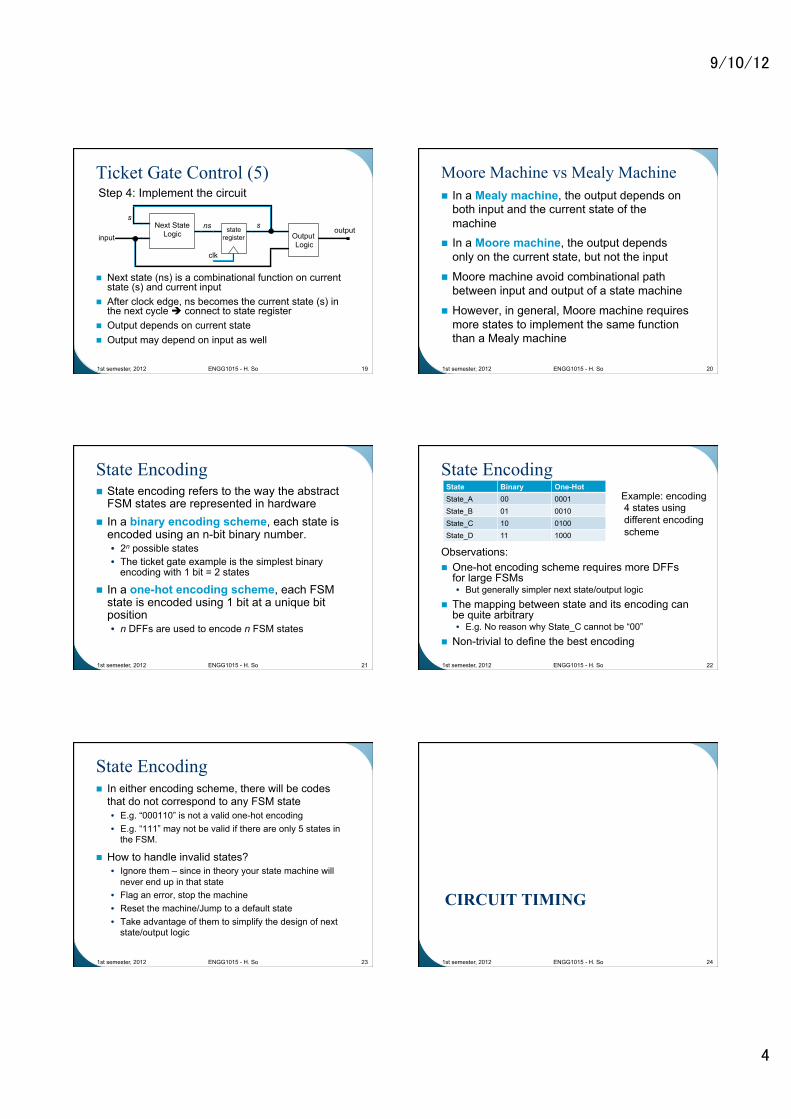
Ticket Gate Control (5)
n Next state (ns) is a combinational function on current state (s) and current input
n After clock edge, ns becomes the current state (s) in the next cycle è connect to state register
n Output depends on current state n Output may depend on input as well
1st semester, 2012 ENGG1015 - H. So 19
Next State Logic input
state register
s
clk
s ns output
Output Logic
Step 4: Implement the circuit Moore Machine vs Mealy Machine n In a Mealy machine, the output depends on
both input and the current state of the machine
n In a Moore machine, the output depends only on the current state, but not the input
n Moore machine avoid combinational path between input and output of a state machine
n However, in general, Moore machine requires more states to implement the same function than a Mealy machine
1st semester, 2012 ENGG1015 - H. So 20
State Encoding n State encoding refers to the way the abstract
FSM states are represented in hardware n In a binary encoding scheme, each state is
encoded using an n-bit binary number. • 2n possible states • The ticket gate example is the simplest binary
encoding with 1 bit = 2 states
n In a one-hot encoding scheme, each FSM state is encoded using 1 bit at a unique bit position • n DFFs are used to encode n FSM states
1st semester, 2012 ENGG1015 - H. So 21
State Encoding
Observations: n One-hot encoding scheme requires more DFFs
for large FSMs • But generally simpler next state/output logic
n The mapping between state and its encoding can be quite arbitrary • E.g. No reason why State_C cannot be “00”
n Non-trivial to define the best encoding
1st semester, 2012 ENGG1015 - H. So 22
State Binary One-Hot State_A 00 0001 State_B 01 0010 State_C 10 0100 State_D 11 1000
Example: encoding 4 states using different encoding scheme
State Encoding n In either encoding scheme, there will be codes
that do not correspond to any FSM state • E.g. “000110” is not a valid one-hot encoding • E.g. “111” may not be valid if there are only 5 states in
the FSM.
n How to handle invalid states? • Ignore them – since in theory your state machine will
never end up in that state • Flag an error, stop the machine • Reset the machine/Jump to a default state • Take advantage of them to simplify the design of next
state/output logic
1st semester, 2012 ENGG1015 - H. So 23
CIRCUIT TIMING
1st semester, 2012 ENGG1015 - H. So 24
9/10/12
5
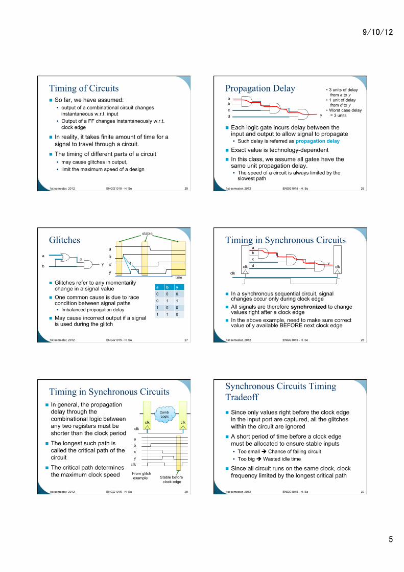
Timing of Circuits n So far, we have assumed:
• output of a combinational circuit changes instantaneous w.r.t. input
• Output of a FF changes instantaneously w.r.t. clock edge
n In reality, it takes finite amount of time for a signal to travel through a circuit.
n The timing of different parts of a circuit • may cause glitches in output, • limit the maximum speed of a design
1st semester, 2012 ENGG1015 - H. So 25
Propagation Delay
n Each logic gate incurs delay between the input and output to allow signal to propagate • Such delay is referred as propagation delay
n Exact value is technology-dependent n In this class, we assume all gates have the
same unit propagation delay. • The speed of a circuit is always limited by the
slowest path
1st semester, 2012 ENGG1015 - H. So 26
a b
c
d y
• 3 units of delay from a to y
• 1 unit of delay from d to y
• Worst case delay = 3 units
Glitches
n Glitches refer to any momentarily change in a signal value
n One common cause is due to race condition between signal paths • Imbalanced propagation delay
n May cause incorrect output if a signal is used during the glitch
1st semester, 2012 ENGG1015 - H. So 27
y
a
b
x
a
b
x
y
1
stable
a b y
0 0 0
0 1 1
1 0 0
1 1 0
time
Timing in Synchronous Circuits
n In a synchronous sequential circuit, signal changes occur only during clock edge
n All signals are therefore synchronized to change values right after a clock edge
n In the above example, need to make sure correct value of y available BEFORE next clock edge
1st semester, 2012 ENGG1015 - H. So 28
a b
c
d y clk clk
clk
Timing in Synchronous Circuits n In general, the propagation
delay through the combinational logic between any two registers must be shorter than the clock period
n The longest such path is called the critical path of the circuit
n The critical path determines the maximum clock speed
1st semester, 2012 ENGG1015 - H. So 29
clk
clk clk
Comb Logic
a
b
x
y
clk
1
From glitch example Stable before
clock edge
Synchronous Circuits Timing Tradeoff n Since only values right before the clock edge
in the input port are captured, all the glitches within the circuit are ignored
n A short period of time before a clock edge must be allocated to ensure stable inputs • Too small è Chance of failing circuit • Too big è Wasted idle time
n Since all circuit runs on the same clock, clock frequency limited by the longest critical path
1st semester, 2012 ENGG1015 - H. So 30
9/10/12
6
Summary n Synchronous sequential circuits contain one
single clock • All FFs connected to the same clock • All signal change synchronized to the same clock edge
n State machine is an important abstraction for computation • Straight forward implementation as synchronous
sequential logic
n Propagation delay of logic gates determines the highest frequency a synchronous sequential circuit can run
1st semester, 2012 ENGG1015 - H. So 31