Embed Size (px)
Citation preview
CALL US T1-888-POWCALL US T1-888-POW
INSTRUCTION MANUALFOR
DIGITAL EXCITATION CONTROL SYSTEMModels: DECS 32-15, 63-15 & 125-15Part Numbers: 9 2653 00 106 through -111
For DECS Software Version 2.0.5 and Subsequent
Publication Number: 9 2653 00 993Revision : E 01/2000
ODAY ER-58
REQUEST A QUOTE [email protected]
SHOP ONLINE www.genpowerusa.com
ODAY ER-58
REQUEST A QUOTE [email protected]
SHOP ONLINE www.genpowerusa.com

DECS INTRODUCTION i
INTRODUCTION
This manual provides information concerning the operation and installation of a DECS 32-15, 63-15, &125-15 Digital Excitation Control System. To accomplish this, the following is provided.
• Specifications
• Functional Description
• Installation Information
• Operation
• Communications
• Maintenance
WARNINGTO AVOID PERSONAL INJURY OR EQUIPMENT DAMAGE, ONLY QUALIFIEDPERSONNEL SHOULD PERFORM THE PROCEDURES PRESENTED IN THISMANUAL.
CAUTIONThe case of the DECS must be properly connected to a suitable power system ground toensure proper operation and to prevent the possibility of electrical shock.
CAUTIONDo not megger or hipot the generator with the DECS connected. Do not megger or hipotthe DECS. To do so will damage the internal electronics of the DECS.
CAUTIONThe DECS field output terminals (F+ and F-) should NEVER be disconnected or shortedduring operation. Disconnecting or shorting the field terminals can result in permanentdamage to the DECS unit.Large capacitors in the Power Module must be allowed to discharge before shorting thefield terminals. Excessive current drawn through a short across the field terminals willcause permanent damage to the DECS unit.If a power switch is desired to disconnect the power, it should be connected to the DECSpower input terminals (3 and 4).
CALL US TODAY 1-888-POWER-58
REQUEST A QUOTE [email protected]
SHOP ONLINE www.genpowerusa.com
CALL US TODAY 1-888-POWER-58
REQUEST A QUOTE [email protected]
SHOP ONLINE www.genpowerusa.com

ii DECS INTRODUCTION
First Printing: October 1997
Printed in USA
© 1997, 1998, 1999, 2000, Basler Electric Co., Highland, IL 62249
January 2000
CONFIDENTIAL INFORMATIONOF BASLER ELECTRIC COMPANY, HIGHLAND, IL. IT IS LOANED FORCONFIDENTIAL USE, SUBJECT TO RETURN ON REQUEST, AND WITH THEMUTUAL UNDERSTANDING THAT IT WILL NOT BE USED IN ANY MANNERDETRIMENTAL TO THE INTEREST OF BASLER ELECTRIC COMPANY.
It is not the intention of this manual to cover all details and variations in equipment, nordoes this manual provide data for every possible contingency regarding installation oroperation. The availability and design of all features and options are subject tomodification without notice. Should further information be required, contact BaslerElectric Company, Highland, Illinois.
BASLER ELECTRICROUTE 143, BOX 269
HIGHLAND, IL 62249 USAhttp://www.basler.com, [email protected]
PHONE 618-654-2341 FAX 618-654-2351
CALL US TODAY 1-888-POWER-58
REQUEST A QUOTE [email protected]
SHOP ONLINE www.genpowerusa.com
CALL US TODAY 1-888-POWER-58
REQUEST A QUOTE [email protected]
SHOP ONLINE www.genpowerusa.com

CALL US TO1-888-POWERCALL US TO1-888-POWER
DECS INTRODUCTION iii
CONTENTSSECTION 1 GENERAL INFORMATION............................................................................................. 1-1
General ............................................................................................................................ 1-1Specifications ................................................................................................................... 1-2
SECTION 2 FUNCTIONAL DESCRIPTION........................................................................................ 2-1
Power Supply ................................................................................................................... 2-1Power Amplifier Stage...................................................................................................... 2-1Display ............................................................................................................................. 2-1Voltage Matching Circuitry ............................................................................................... 2-1Phase B Current Sensing Circuit ..................................................................................... 2-2RMS Sensing Circuitry ..................................................................................................... 2-2Pushbutton/Contact Input Circuitry .................................................................................. 2-2Auxiliary Input Circuitry .................................................................................................... 2-2Serial Communications Port............................................................................................. 2-2Microprocessor ................................................................................................................ 2-2Alarm................................................................................................................................ 2-2Manual Excitation Control Circuit ..................................................................................... 2-3
SECTION 3 INSTALLATION............................................................................................................... 3-1
Mounting .......................................................................................................................... 3-1Interconnection................................................................................................................. 3-5
Remote Adjust ........................................................................................................... 3-5Sensing Voltage ........................................................................................................ 3-5Power Output............................................................................................................. 3-5Power Input ............................................................................................................... 3-6Paralleling Input ......................................................................................................... 3-6Field Flashing ............................................................................................................ 3-7Voltage Matching Input.............................................................................................. 3-7
SECTION 4 OPERATION.................................................................................................................... 4-1
General ............................................................................................................................ 4-1Preliminary Set-Up........................................................................................................... 4-3Adjustments ..................................................................................................................... 4-3
Course Voltage Adjustment....................................................................................... 4-3Fine Voltage Adjustment ........................................................................................... 4-4Fine Voltage Adjustment Band .................................................................................. 4-4Manual Mode Switch ................................................................................................. 4-4Manual Mode Setpoint............................................................................................... 4-4Underfrequency ......................................................................................................... 4-4Volts per Hertz Slope................................................................................................. 4-4Stability Range Select ............................................................................................... 4-5Stability Level Adjustment ......................................................................................... 4-5VAR/Power Factor Adjustments ................................................................................ 4-8Droop Adjustment...................................................................................................... 4-8Underexcitation Limiting/Overexcitation Limiting..................................................... 4-10Overexcitation Select............................................................................................... 4-10Softstart ................................................................................................................... 4-10DECS Sensing Configuration .................................................................................. 4-11Current Transformer Primary Rating ....................................................................... 4-11Sensing Potential Transformer Ratio....................................................................... 4-11Voltage Matching..................................................................................................... 4-11
DAY -58
REQUEST A QUOTE [email protected]
SHOP ONLINE www.genpowerusa.com
DAY -58
REQUEST A QUOTE [email protected]
SHOP ONLINE www.genpowerusa.com

iv DECS INTRODUCTION
CONTENTS - Continued
SECTION 4 OPERATION - Continued
Voltage Matching Band............................................................................................ 4-11Voltage Matching Speed.......................................................................................... 4-12Voltage Matching Step............................................................................................. 4-12
Front Panel Operation.................................................................................................... 4-12Status and Diagnostic LED’s ................................................................................... 4-12Alpha Numeric Display ............................................................................................ 4-13
DECS Communication Interface Module (DCIM)........................................................... 4-14DECS Alarm Enable/Disable ................................................................................... 4-14DECS Shutdown Enable/Disable............................................................................. 4-14
SECTION 5 DCIM DOS COMMUNICATIONS .................................................................................... 5-1
Introduction ...................................................................................................................... 5-1Hardware Specifications .................................................................................................. 5-1DCIM Interconnection ...................................................................................................... 5-2DCIM Software Installation............................................................................................... 5-2Main Menu Usage ............................................................................................................ 5-3Successful Link Message ................................................................................................ 5-3Interface Problem Screen ................................................................................................ 5-4Adjustment Menu ............................................................................................................. 5-4
Definitions of Top Menu Commands ......................................................................... 5-4Definitions of Adjustments ......................................................................................... 5-5
PID Window ..................................................................................................................... 5-9Step Response Window................................................................................................... 5-9Monitor Window ............................................................................................................... 5-9Saving Data Message................................................................................................... 5-10Help Window .................................................................................................................. 5-10File Transfer Window ..................................................................................................... 5-11Option Menu................................................................................................................... 5-12Alarm Control Menu ....................................................................................................... 5-12Shut Down Control Menu ............................................................................................... 5-12Extra Adjustment Menu.................................................................................................. 5-13Quit Menu....................................................................................................................... 5-13Troubleshooting Procedure............................................................................................ 5-14PID Window Instructions ................................................................................................ 5-15
Introduction.............................................................................................................. 5-15Definitions................................................................................................................ 5-15Stability Parameter Generation Software ................................................................ 5-15Additional Adjustments ............................................................................................ 5-16
SECTION 6 DECS Windows SOFTWARE ..................................................................................... 6-1
Introduction ...................................................................................................................... 6-1Installation ........................................................................................................................ 6-1
Operating Requirements ........................................................................................... 6-1Installing the Program On Your PC Using Microsoft Windows ................................. 6-1Configuring the System ............................................................................................. 6-1
Initializing Communications with the DECS Windows Software .................................. 6-1Initializing Communications ....................................................................................... 6-2
Changing Settings............................................................................................................ 6-4Sending and Receiving Settings ...................................................................................... 6-5
Send to DECS ........................................................................................................... 6-5Get from DECS.......................................................................................................... 6-5EEPROM ................................................................................................................... 6-5
CALL US TODAY 1-888-POWER-58
REQUEST A QUOTE [email protected]
SHOP ONLINE www.genpowerusa.com
CALL US TODAY 1-888-POWER-58
REQUEST A QUOTE [email protected]
SHOP ONLINE www.genpowerusa.com

DECS INTRODUCTION v
CONTENTS - Continued
SECTION 6 DECS Windows SOFTWARE - Continued
Settings Definitions .......................................................................................................... 6-5System Configuration - Operation Mode ................................................................... 6-5System Configuration - Limiter Mode ........................................................................ 6-6System Configuration - Phase Configuration ............................................................ 6-6System Configuration - PT/CT Settings..................................................................... 6-6System Configuration - Version Number ................................................................... 6-6Setting Adjustments - Block 1.................................................................................... 6-6Setting Adjustments - Block 2.................................................................................... 6-8Setting Adjustments - Block 3.................................................................................... 6-9Control Gain ............................................................................................................ 6-10Step Response ........................................................................................................ 6-12Alarm/Shutdown Options......................................................................................... 6-13Metering................................................................................................................... 6-15
Saving, Printing, and Opening Files............................................................................... 6-15Saving Files ............................................................................................................. 6-16Printing Files............................................................................................................ 6-17Opening Files .......................................................................................................... 6-18Default Settings Open ............................................................................................. 6-19
PID Window ................................................................................................................... 6-19PID Calculations Base on Input Values................................................................... 6-19Retrieving Existing Data from PID List .................................................................... 6-20
Terminating Communications ........................................................................................ 6-22
SECTION 7 MAINTENANCE............................................................................................................... 7-1
Preventive Maintenance................................................................................................... 7-1Corrective Maintenance ................................................................................................... 7-1Warranty and Repair Service........................................................................................... 7-1Troubleshooting ............................................................................................................... 7-1
No Voltage Build-up................................................................................................... 7-1Low Output Voltage ................................................................................................... 7-2High Output Voltage .................................................................................................. 7-3Generator Does Not Respond as Adjustments Are Made......................................... 7-3Poor Voltage Regulation............................................................................................ 7-3Generator Output Unstable ....................................................................................... 7-3Front Panel UF LED is Illuminated ............................................................................ 7-4Front Panel OVEREXC LED is illuminated................................................................ 7-4No Droop or Negative Droop..................................................................................... 7-4No Voltage Matching ................................................................................................. 7-5Fine Voltage Adjust Band Not Centered Around the CoarseVoltage Adjust Setting ............................................................................................... 7-5No Communication With DCIM Unit .......................................................................... 7-6
SECTION 8 REPLACEMENT PARTS................................................................................................. 8-1
General ............................................................................................................................ 8-1
SECTION 9 MANUAL CHANGE INFORMATION .............................................................................. 9-1
Changes........................................................................................................................... 9-1
CALL US TODAY 1-888-POWER-58
REQUEST A QUOTE [email protected]
SHOP ONLINE www.genpowerusa.com
CALL US TODAY 1-888-POWER-58
REQUEST A QUOTE [email protected]
SHOP ONLINE www.genpowerusa.com

CALL US TOD1-888-POWER-CALL US TOD1-888-POWER-
GENERAL INFORMATION 1-1
SECTION 1 ••••GENERAL INFORMATION
GENERAL
The Basler Digital Excitation Control System (DECS) is an electronic, solid-state, micro-processorbased control device. DECS regulates the voltage output of a brush-type or brushless, ac generatorby controlling the current into the generator exciter field. Input power to the DECS can be from amulti-pole, high-frequency, permanent magnet generator (PMG), or from the generator output whenused as a conventional shunt-excited excitation system through the DECS Power Module. Thismodule is included with every DECS.
Refer to Figure 1-1 for the DECS style chart. In the example shown in the chart, a DECS 32-15A2C1VXX is specified. This is a DECS which provides 32 Vdc at a maximum of 15 Adc to the field.An available option which was not selected is VAR/PF control. An option that was selected isOverexcitation Limiting/Underexcitation Limiting. An option for 1 or 5A secondary currenttransformers, was selected for 1 Amp. The software version number, which is intended for generalreference only, will be added at the factory to describe the software version installed.
MODEL NUMBER
DECS 32-15DECS 63-15DECS 125-15
OPTION 2EXCITATION
CURRENT LIMITING
1 - NO UEL/OEL
2 - UEL/OEL
SOFTWARE VERSION
VAR/PF CONTROL
A - NO VAR/PFB - VAR/PF
C - VOLTAGE MATCHING
VXX - VERSION
1 - 1A CT SECONDARY
5 - 5A CT SECONDARY
NUMBER
D2659-0608-12-97
A 2 1 VXXCDECS 32-15 -
OPTION 3 OPTION 4OPTION 1
Figure 1-1. DECS Style Chart
AY 58
REQUEST A QUOTE [email protected]
SHOP ONLINE www.genpowerusa.com
AY 58
REQUEST A QUOTE [email protected]
SHOP ONLINE www.genpowerusa.com

1-2 GENERAL INFORMATION
SPECIFICATIONS
Refer to Tables 1-1 and 1-2 for the DECS electrical specifications, Table 1-3 for generator fieldrequirements, and to Table 1-4 for the DECS physical specifications.
Table 1-1. DECS Electrical Specifications
Regulation Accuracy: Regulates within ±0.25% of nominal, no-load to full-load.
Power Input: See Table 1-2.
Input Sensing: 120, 208, 240, 416, 480, or 600 Vac ±10%, 60 Hz nominal,100, 220, or 400 Vac ±10%, 50 nominal,Selectable single-phase or three-phase RMS.
Sensing Burden: <1 VA per phase.
External Voltage AdjustRange:
Customer-adjustable from ±6V to ±60V in 0.5V steps.
Underfrequency (V/Hz)Limiting:
Customer adjustable from continuous to 3 times V/Hz. Transitionfrequency ("corner" frequency) is adjustable from 40 Hz to 65 Hz.(Refer to Figure 1-2 for V/Hz curves.)
Parallel Compensation: Can use either reactive droop or reactive differential (cross-current)compensation. Adjustable 20% voltage droop with optional 1 A orless or 5 A or less input. For parallel compensation, burden <1VA.
Accessory Input: A ±3 Vdc input results a ±30% change in regulated voltage. Inputimpedance is 1k ohms.
Alarm Indication: Triac output rated at 30 Vdc (24V Nominal) at 150 mA latched withexternal Dc source.
Overvoltage Protection: Factory preset at 35% above nominal with a 0.75 sec. time delay.
Soft-Start Ability: Included with customer adjustable rate of build-up.
Solid State (Internal)Build-up:
Minimum of 8 Vac power input required.
Over ExcitationLimiting:
See Figure 1-3.
Under ExcitationLimiting:
Adjustable from 0-100% maximum reactive current.
Manual ExcitationControl:
Regulates field current from 0.0 Amps to 25.0 Amps.
Voltage Matching: Matches utility bus RMS voltage with generator output RMS voltageto within 1%.
CALL US TODAY 1-888-POWER-58
REQUEST A QUOTE [email protected]
SHOP ONLINE www.genpowerusa.com
CALL US TODAY 1-888-POWER-58
REQUEST A QUOTE [email protected]
SHOP ONLINE www.genpowerusa.com

GENERAL INFORMATION 1-3
Table 1-2. DECS Electrical Specifications - Power Input Requirements (50-400 Hz)
DECS Model No. Nominal
Input
Power Input Into Power Module(50 - 400 Hz)
Burden
DECS 32-15-XXXX 60 VRMS 56 - 70 VRMS ±10%, 1 or 3 Phase 780 VA
DECS 63-15-XXXX 120 VRMS 100 - 139 VRMS ±10%, 1 or 3 Phase 1570 VA
DECS 125-15-XXXX 240 VRMS 190 - 277 VRMS ±10%, 1 or 3 Phase 3070 VA
Table 1-3. Generator Field Requirements
DECS 32-15 DECS 63-15 DECS 125-15
Minimum Field Resistance at 25°C 2.13 ohms 4.2 ohms 8.3 ohms
Rated Continuous Field Voltage 32 Vdc 63 Vdc 125 Vdc
Rated 10-Second Forcing VoltageFor Rated Power Input Voltage*
50 Vdc 100 Vdc 200 Vdc
Rated Maximum Field Current 15 Adc 15 Adc 15 Adc
Rated 10-Second Forcing Current 30 Adc 30 Adc 30 Adc
Rated 120 Second ForcingCurrent
20 Adc 20 Adc 20 Adc
The above parameters are with nominal RMS voltage levels listed in Table 1-2 above.
* Forcing voltages may be up to 50% greater than listed if:
1) 3 Phase input power is used, OR2) Field current is significantly lower than that listed.
Please consult factory for further details.
Table 1-4. DECS Physical Specifications
UL Recognized/ CSA Certified
UL Recognized per Standard 508, UL File No. E 97035. CSACertified per Standard CAN/CSA-C22.2 No. 14-M91, CSA FileNo. LR 23131-139. Note: Output contacts are not ULrecognized/CSA Certified for voltages greater than 250 volts.
Operating Temperature: -40°C to +60°C.
Storage Temperature: -40°C to +85°C.
Shock: 15 G's in each of three mutually perpendicular planes.
Vibration: 1 G at 5 to 26 Hz.0.036" double amplitude at 27 to 52 Hz.5 G's at 53 to 500 Hz.
Weight: 9 lbs. (4.05 kg) net, 12 lbs. (5.40 kg) shipping.
CALL US TODAY 1-888-POWER-58
REQUEST A QUOTE [email protected]
SHOP ONLINE www.genpowerusa.com
CALL US TODAY 1-888-POWER-58
REQUEST A QUOTE [email protected]
SHOP ONLINE www.genpowerusa.com

1-4 GENERAL INFORMATION
Table 1-5. DECS Power Transformer Selection Chart
Primary
DECS 32-15-XXX
DECS 63-15-XXX DECS 125-15-XXX
Voltage3 Phase 3 Phase 1 Phase 3 Phase 1 Phase
240 BE 22209-001 BE 12819-001
480 BE 24588-001 BE 26103-001 BE 22209-001 BE 26660-001 BE 21819-001
600 BE 11050-001 BE 26819-001 BE 22209-001
2400 BE 20221-001 BE 13487-001 BE 21027-001 BE 12818-001
4160 BE 21027-001 BE 13487-001 BE 21027-001 BE 12818-001
7200 BE 22136-001 BE 25921-001 BE 22136-001
13800 BE 21327-001 BE 26728-001 BE 21327-001
Note to the customer: If your transformer needs cannot be satisfied from this chart, please consult thefactory.
CALL US TODAY 1-888-POWER-58
REQUEST A QUOTE [email protected]
SHOP ONLINE www.genpowerusa.com
CALL US TODAY 1-888-POWER-58
REQUEST A QUOTE [email protected]
SHOP ONLINE www.genpowerusa.com

GENERAL INFORMATION 1-5
18Hz
1 0 0 %
S E T P O I N T
1 DECS operat ion is not speci f ied for generator
S E N S I N GV O L T A G E
G E N E R A T O R
0 V/Hz
1 V/Hz
3 V/Hz
3 0 V A C
vol tages below 18Hz. Power must be removedfrom DECS below th is f requency.
2 DECS operat ion is not speci f ied for sensing vol tages below 30VAC.
per iods may overheat the generator.3 Operat ion above the 1V/Hz curve for extended
3
2
1
F R E Q U E N C Y
U N D E R F R E Q U E N C Y
(UF)
D2659-1408-14-97
Figure 1-2. Typical Volts per Hertz Curves
DE
CS
OU
TP
UT
CU
RR
EN
T
ID
C
T IME IN SECONDS
REGION1
REGION2
REGION3
0-10(OET1)
30ADC
0-120 sec
(OET2)
CONTINUOUS 1-15 AMPS(OEI3)
1-20ADC(OEI2)
D2659-0708-12-97
Figure 1-3. Overexcitation Limiter
CALL US TODAY 1-888-POWER-58
REQUEST A QUOTE [email protected]
SHOP ONLINE www.genpowerusa.com
CALL US TODAY 1-888-POWER-58
REQUEST A QUOTE [email protected]
SHOP ONLINE www.genpowerusa.com

CALL US TOD1-888-POWERCALL US TOD1-888-POWER
FUNCTIONAL DESCRIPTION 2-1
SECTION 2 •••• FUNCTIONAL DESCRIPTION(Refer to Figure 2-1)
M I C R OP R O C E S S O R
SERIALC O M M U N I C A T I O N S
P O R T
P O W E RAMPLIF IER
S T A G E
INPUTP O W E R
P O W E RSUPPLY
O P E R A T I N GV O L T A G E
FIELDO U T P U T
THREE PHASERMS SENSING
CIRCUITRY
P U S H B U T T O N / C O N T A C TINPUT CIRCUITRY
V O L T A G EM A T C H I N GCIRCUITRY
PHASE B CURRENTSENSING CIRCUIT
DISPLAY
A L A R M
M A N U A LV O L T A G EC O N T R O L
D2659-0801-17-00
AUXIL IARYINPUT
CIRCUITRY
Figure 2-1. DECS-15 Block Diagram
POWER SUPPLY
The Power Supply converts the input voltage, rectifies and filters it, and supplies all the operatingvoltages required by the internal circuitry of the DECS. A minimum of 8 Vac into the DECS PowerModule is required to allow automatic generator line voltage buildup when using the DECS.
POWER AMPLIFIER STAGE
The Power Amplifier receives input power and will output the field voltage and current depending uponthe timing of the firing pulses from the microprocessor. The Power Amplifier uses a single IGBT forsupplying the field voltage and current required by the exciter.
DISPLAY
The front panel Display consists of nine LEDs and an alphanumeric display. The LEDs continuallymonitor the unit's condition. The four-character alphanumeric display is for system set-up/adjustmentand the monitoring of select conditions. The LED and the alphanumeric display are controlled by themicroprocessor.
VOLTAGE MATCHING CIRCUITRY
This circuit will control the generator output and match it to the bus prior to synchronizing. This circuitis enabled via the front panel of the DECS or the optional DECS Communication Interface Module(DCIM).
AY -58
REQUEST A QUOTE [email protected]
SHOP ONLINE www.genpowerusa.com
AY -58
REQUEST A QUOTE [email protected]
SHOP ONLINE www.genpowerusa.com

2-2 FUNCTIONAL DESCRIPTION
PHASE B CURRENT SENSING CIRCUIT
This circuit monitors the generator current output on phase B. This signal is rectified and convertedwithin the DECS to a digital signal for use by the Microprocessor. It is used for measuring PF andVARs. It is also used when paralleling the generators.
RMS SENSING CIRCUITRY
This circuit monitors the generator voltage output on any or all three phases. This signal is rectifiedand converted within the DECS to a digital signal for use by the microprocessor. It is selectablethrough the adjustment menu on the front panel of the DECS.
PUSHBUTTON/CONTACT INPUT CIRCUITRY
This circuit provides a means for the front panel pushbuttons and the external switch contacts tointeract with the microprocessor and control the DECS operation.
AUXILIARY INPUT CIRCUITRY
This circuit allows an external device to control the DECS output and, thus the generator outputvoltage. This is accomplished by receiving a ±3 Vdc voltage. The circuit induces a 1K ohms burdenon the ±3 Vdc customer supplied source. A ±30% change in generator output voltage is associatedwith a ±3 Vdc signal received into terminals A & B.
Table 2-1.
DECS Style Vdc Applied AtDECS Terminals
Change In Gen.Output Voltage
DECS Display"ACC" Polarity
DECS XXX-15-XXC + @ A - @ B Increase +
SERIAL COMMUNICATIONS PORT
The Serial Communications Link is a connector which allows communication between the DECS anda PC through the use of the optional DCIM (DECS Communication Interface Module) and the BaslerSoftware Diskette provided with the DCIM. The port is used for troubleshooting and re-programmingof the DECS. A more detailed description is provided later in this manual.
MICROPROCESSOR
The microprocessor controls all functions of the DECS by the use of its built-in programming. It hasan EEPROM which provides a non-volatile memory for storing settings after power is removed fromthe unit. This enables customer programming of the setpoints before and after unit installation.
ALARM
This circuit is a triac output which is controlled by the microprocessor and the internal overexcitationhardware. This circuit is a protective feature which is rated at 30 Vdc at 150 mA. The triac, if enabled,will latch if monitored trouble conditions occur, and then stay latched even after power is removedfrom the DECS unit. Upon repowering the DECS, the triac will remain latched until the external DCsource is de-energized.
CALL US TODAY 1-888-POWER-58
REQUEST A QUOTE [email protected]
SHOP ONLINE www.genpowerusa.com
CALL US TODAY 1-888-POWER-58
REQUEST A QUOTE [email protected]
SHOP ONLINE www.genpowerusa.com

FUNCTIONAL DESCRIPTION 2-3
MANUAL EXCITATION CONTROL CIRCUITRY
The manual excitation control allows an operator to manually set the amount of the dc excitationcurrent output of DECS. Once set, DECS will regulate that current. This circuit is also used for thecase of the loss of sensing voltage. DECS will regulate the dc excitation current setpoint if the sensingvoltage is lower than 25% of the generator terminal voltage for more than a customer adjustableactivation delay time. This circuit is not intended as a back-up system to the Automatic mode ofoperation. It will be useful in the commissioning of the generator system.
CALL US TODAY 1-888-POWER-58
REQUEST A QUOTE [email protected]
SHOP ONLINE www.genpowerusa.com
CALL US TODAY 1-888-POWER-58
REQUEST A QUOTE [email protected]
SHOP ONLINE www.genpowerusa.com

CALL US1-888-POCALL US1-888-PO
INSTALLATION 3-1
SECTION 3 •••• INSTALLATION
MOUNTING
The DECS is normally located in the generator conduit box, but is also designed to operate in remoteswitchgear cubicles with convection cooling. When remotely mounted, the DECS may either bemounted through the panel or behind the panel with the optional behind the panel mounting kit.Figures 3-1 through 3-3 provide the DECS outline dimensions and Figures 3-4 and 3-5 provide theDECS Behind the Panel Mounting Kit dimensions. Figure 3-6 is the DECS Power Module dimensions.
(123)
(25)
(203)
(25)
8.00
1.00
1.00
4.84
D2659-0908-12-97
Figure 3-1. DECS Outline Drawing, Front View
TODAY WER-58
REQUEST A QUOTE [email protected]
SHOP ONLINE www.genpowerusa.com
TODAY WER-58
REQUEST A QUOTE [email protected]
SHOP ONLINE www.genpowerusa.com

3-2 INSTALLATION
(203)(229)
(13).50
8.009.00
MAX.
.50(123)4.84
(13)
(149)
5.85MAX.
(17).68
.218 DIA. MTG. HOLE(6) (4 PLCS)
08-12-97D2659-10
Bas
ler
Figure 3-2. DECS Outline Drawing, Rear View
(328)
(265)
(179)
12.90
10.45
7.00
NOTE: ALL D IMENSIONS ARE INI N C H E S
(MILL IMETERS) .
D2659-1108-12-97
Figure 3-3. DECS Outline Drawing, Side View
CALL US TODAY 1-888-POWER-58
REQUEST A QUOTE [email protected]
SHOP ONLINE www.genpowerusa.com
CALL US TODAY 1-888-POWER-58
REQUEST A QUOTE [email protected]
SHOP ONLINE www.genpowerusa.com

INSTALLATION 3-3
(278) (229)
(76)
(76)
(22)
(51)
(20)
(30)
(144)
(104)(40)
(184)
(203)
(271)
(34)
(43)
(30)
(40) (104)
(123)
5 .652.780
2.000
3.000
3.000
1.200
10.944
1.562 4.088
9.000
.870
4.0881.562
1.187 4.838
10.675
1.712
8.000
1.337
7.250
1.638
.871
3.827
2.614(66)
(97)
(42)
(22)
.8662.1254.998 1.547(127) (54) (40) (22)
NOTE:
ALL DIMENSIONS ARE IN INCHES (MILL IMETERS) .
10-32 WELDNUT (TYP. 20 PL)
D2659-1208-12-97
Figure 3-4. Behind the Panel Mounting Kit Outline Drawing
P/N: 9 2653 04 100
CALL US TODAY 1-888-POWER-58
REQUEST A QUOTE [email protected]
SHOP ONLINE www.genpowerusa.com
CALL US TODAY 1-888-POWER-58
REQUEST A QUOTE [email protected]
SHOP ONLINE www.genpowerusa.com

3-4 INSTALLATION
6.69 P.03.378
7.45 P.03
.609
9.00 P.037.874
.281 DIA. HOLES, (PLCS)
10-32 WELD NUTS (4 PLCS)
(200) (229)
(15)
(189)
(170)(10)
12.85 P .03(326)
5.72 P .03(146)
D2659-2108-14-97
Figure 3-5. Rear Panel Mounting Kit Outline DrawingP/N: 9 2653 00 026
(105)4.138 MAX.
27.0+-
2 . 00 . 5
0 . 52 . 0
-+
(686)
7.750 MAX.(197)
.156 DIA. HOLE(4) (4 PLCS)(686)
9.0
4.375
4.80 MAX.
(111)
(122)
.187
2.50
.75
4.000(64)(102)
(19)
(5)
S /N
Highland, I l l ino is USABasler Electr ic
R
P/N : 9 2849 00 101
D E C S P O W E R M O D U L E
ALL DIMENSIONS ARE IN INCHES (MILLIMETERS). POWER DISSIPATION: 87 WATTSWEIGHT= 5#
D2659-1303-20-98
Figure 3-6. DECS Power Module Dimensions
CALL US TODAY 1-888-POWER-58
REQUEST A QUOTE [email protected]
SHOP ONLINE www.genpowerusa.com
CALL US TODAY 1-888-POWER-58
REQUEST A QUOTE [email protected]
SHOP ONLINE www.genpowerusa.com

INSTALLATION 3-5
INTERCONNECTION
Connect the DECS as shown in Figures 3-7 through 3-11 and in accordance with the followingparagraphs.
CAUTION
The case of the DECS must be properly connected to a suitable power systemground to ensure proper operation and to prevent the possibility of electricalshock.
CAUTION
Do not megger or hipot the generator with the DECS connected. Do not meggeror hipot the DECS. To do so will damage the internal electronics of the DECS.
NOTEWhen shunt powered on generators with output voltages greater than the requirementsof Table 1-2, an external potential transformer must be used to provide the proper inputpower to the DECS Power Module. Refer to Table 1-5 for power PT selection.
(1) Whenever a potential transformer is used for sensing, an open circuit on the primary side of thetransformer will cause maximum forcing from the regulator.
(2) Verify that all connections are tight and secured from possible vibration.
Remote Adjust
If a Remote Voltage Adjust is required, a single-pole, double-throw, spring-return, center-off, switchrated for 240 Vac, 1 A is best suited. To connect this switch, the center pole, or common terminal,must be connected to DECS terminal 7. The other two (2) poles or terminals are connected to DECSterminals 6U and 6D. Shorting terminals 6U to 7 causes the DECS to raise the setpoint of the modeof operation it is in; i.e., voltage, manual VARs or P.F. Similarly, shorting 6D to 7 causes the setpointto be lowered. Care must be taken because "input power" voltage is present across terminals 6U, 6D,and 7. This connection can be made using any wire gauge from 12 to 22 (.3-2.5 mm2). The RemoteVoltage Adjust switch can be mounted up to 150 feet from the DECS when using twisted, shieldedcable.
Sensing Voltage
The DECS comes equipped for three-phase RMS voltage sensing as standard. It can optionally beused with single-phase sensing by connecting the Generator Output Phase A to the DECS Sensingterminal E1 and connecting the Generator Output Phase C to DECS Sensing terminals E2 and E3.The DECS sensing programming must agree with the type of interconnection. From the front panel,the proper phase rotation must be selected for three-phase sensing, A-B-C or A-C-B or the single-phase sensing setting (A-C) must be selected.
Power Output
The DECS Power Output terminals are labeled F+ and F-. These terminals are connected to theExciter Field Leads. Be sure to observe polarity (i.e.: DECS F+ must be connected to Generator F+and DECS F- must be connected to Generator F-).
CALL US TODAY 1-888-POWER-58
REQUEST A QUOTE [email protected]
SHOP ONLINE www.genpowerusa.com
CALL US TODAY 1-888-POWER-58
REQUEST A QUOTE [email protected]
SHOP ONLINE www.genpowerusa.com

3-6 INSTALLATION
CAUTIONThe DECS field output terminals (F+ and F-) should NEVER be disconnected orshorted during operation. Disconnecting or shorting the field terminals can resultin permanent damage to the DECS unit.Large capacitors in the Power Module must be allowed to discharge beforeshorting the field terminals. Excessive current drawn through a short across thefield terminals will cause permanent damage to the DECS unit.If a power switch is desired to disconnect the power, it should be connected to theDECS power input terminals (3 and 4).
Power Input
(Reference Table 1-2.) The DECS Power Input terminals are labeled 3 and 4. The DECS Power Module(Basler P/N: 9 2849 00 101) is included to interface between the PMG or the generator output and theDECS power input. Basler Electric recommends external fusing of the power input with Bussman typeKTK-20 or equivalent fuses.
Paralleling Input
The DECS comes equipped with paralleling provisions as standard. The Paralleling Input terminalsare labeled CTB1 and CTB2. If paralleling is desired, connect the leads from a standard 1 A OR 5 A,1 VA, 5P5, current transformer to these terminals. For cross current (reactive differential), see Figure3-12.
(1) One standard for generator phase rotation is A-B-C. With this phase rotation and three-phasesensing, connect the Generator leads as follows:
Generator Phase DECS Terminal
A E1
B E2
C E3
The Paralleling Transformer must be in the Generator Phase B lead with the H1 towards theGenerator and the X1 to DECS terminal CTB1.
(2) Another standard for generator phase rotation is A-C-B. With this phase rotation and three-phasesensing, connect the Generator leads as follows:
Generator Phase DECS Terminal
A E1
B E3
C E2
The Paralleling Transformer must be in the Generator Phase C lead with the H1 towards theGenerator and the X1 to DECS terminal CTB1.
(3) With single-phase sensing, connect the generator lead as follows:
Generator Phase DECS Terminal
A E1
C E2 & E3
The Paralleling Transformer must be in the Generator Phase B lead with the H1 towards theGenerator and the X1 to the DECS terminal CTB1.
CALL US TODAY 1-888-POWER-58
REQUEST A QUOTE [email protected]
SHOP ONLINE www.genpowerusa.com
CALL US TODAY 1-888-POWER-58
REQUEST A QUOTE [email protected]
SHOP ONLINE www.genpowerusa.com
INSTALLATION 3-7
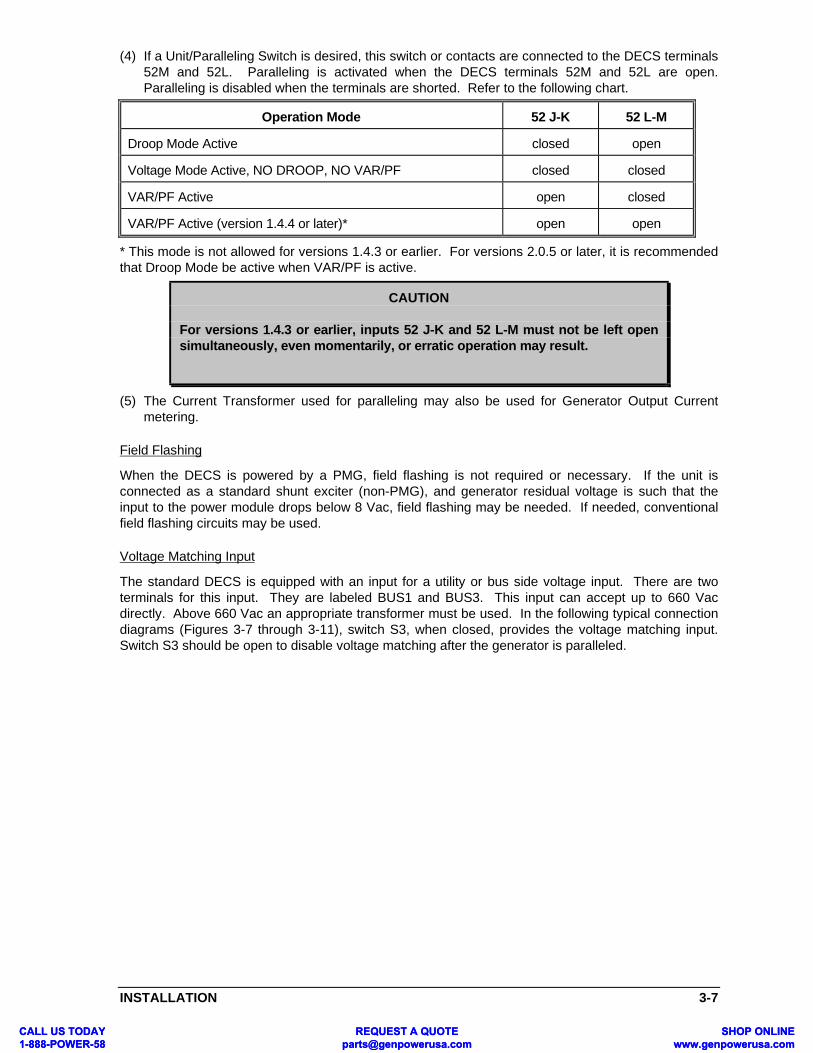
(4) If a Unit/Paralleling Switch is desired, this switch or contacts are connected to the DECS terminals52M and 52L. Paralleling is activated when the DECS terminals 52M and 52L are open.Paralleling is disabled when the terminals are shorted. Refer to the following chart.
Operation Mode 52 J-K 52 L-M
Droop Mode Active closed open
Voltage Mode Active, NO DROOP, NO VAR/PF closed closed
VAR/PF Active open closed
VAR/PF Active (version 1.4.4 or later)* open open
* This mode is not allowed for versions 1.4.3 or earlier. For versions 2.0.5 or later, it is recommendedthat Droop Mode be active when VAR/PF is active.
(5) The Current Transformer used for paralleling may also be used for Generator Output Currentmetering.
Field Flashing
When the DECS is powered by a PMG, field flashing is not required or necessary. If the unit isconnected as a standard shunt exciter (non-PMG), and generator residual voltage is such that theinput to the power module drops below 8 Vac, field flashing may be needed. If needed, conventionalfield flashing circuits may be used.
Voltage Matching Input
The standard DECS is equipped with an input for a utility or bus side voltage input. There are twoterminals for this input. They are labeled BUS1 and BUS3. This input can accept up to 660 Vacdirectly. Above 660 Vac an appropriate transformer must be used. In the following typical connectiondiagrams (Figures 3-7 through 3-11), switch S3, when closed, provides the voltage matching input.Switch S3 should be open to disable voltage matching after the generator is paralleled.
CAUTION
For versions 1.4.3 or earlier, inputs 52 J-K and 52 L-M must not be left opensimultaneously, even momentarily, or erratic operation may result.
CALL US TODAY 1-888-POWER-58
REQUEST A QUOTE [email protected]
SHOP ONLINE www.genpowerusa.com
CALL US TODAY 1-888-POWER-58
REQUEST A QUOTE [email protected]
SHOP ONLINE www.genpowerusa.com

3-8 INSTALLATION
Figure 3-7. DECS Terminal Connections, Rear View
CALL US TODAY 1-888-POWER-58
REQUEST A QUOTE [email protected]
SHOP ONLINE www.genpowerusa.com
CALL US TODAY 1-888-POWER-58
REQUEST A QUOTE [email protected]
SHOP ONLINE www.genpowerusa.com

INSTALLATION 3-9
CT
B
-+A
GE
NB C
FIE
LDO
UT
PU
T
F-
F+
INP
UT
PO
WE
R
34
ALA
RM
CT
B
12
AU
X.
AD
JUS
T
AB
VO
LTA
GE
SE
NS
ING
E3
E2
E1
DE
CS
(D
IGIT
AL
EX
CIT
AT
ION
CO
NT
RO
L S
YS
TE
M)
WIT
H V
OLT
AG
E M
AT
CH
ING
52J
52K
52L
52M
6D7
6U
VA
R/P
FC
ON
TR
OL
CO
NT
RO
LA
DJU
ST
EX
TE
RN
AL
ALR
M+
ALR
M-
PA
RA
LLE
LIN
G
ON
LY R
EQ
UIR
ED
FO
R O
PT
ION
AL
VA
R/P
FC
ON
TR
OL.
VA
R/P
F A
CT
IVE
WIT
H 5
2b O
PE
N,
VA
R/P
F N
OT
AC
TIV
E W
ITH
52b
CLO
SE
D.
PA
RA
LLE
L C
ON
TR
OL
INP
UT
, DR
OO
PA
CT
IVE
WIT
H S
2 O
PE
N, D
RO
OP
NO
T
SW
ITC
H S
1 (S
ING
LE P
OLE
, DO
UB
LET
HR
OW
, SP
RIN
G R
ET
UR
N T
O C
EN
TE
R O
FF
AN
ALO
G IN
PU
T V
OLT
AG
E B
ET
WE
EN
+ O
R-
3 V
DC
. AD
JUS
TM
EN
T F
OR
VO
LTA
GE
SE
TP
OIN
T. R
EF
ER
TO
TA
BLE
2-1
.
NO
TE
S:
52b
S2
S1
SU
PP
LIE
D S
IGN
AL
FO
R A
NN
UN
CIA
TIO
N.
CLO
SE
D T
RIA
C IN
PU
T F
OR
CU
ST
OM
ER
NO
RM
ALL
Y-O
PE
N, E
LEC
TR
ON
ICA
LLY
9
BU
S
13
9 28
49 0
0 10
1
PO
WE
R M
OD
ULE
+- C
BA
FU
SE
8 6
7
7
S3
SID
ES
IDE
PM
G52
12
3
45
AC
TIV
E W
ITH
S2
CLO
SE
D.
TO
GG
LE S
WIT
CH
) A
DJU
ST
S V
OLT
AG
ES
ET
PO
INT
.
RE
CO
MM
EN
DE
D E
XT
ER
NA
L F
US
ES
SH
OU
LD B
EB
US
SM
AN
TY
PE
KT
K-2
0 O
R E
QU
IVA
LEN
T.
SE
NS
ING
PO
TE
NT
IAL
TR
AN
SF
OR
ME
R R
EQ
UIR
ED
IF L
INE
VO
LTA
GE
EX
CE
ED
S 6
60 V
ac.
SH
OW
N W
ITH
3 P
HA
SE
PM
G. F
OR
SIN
GLE
PH
AS
E P
MG
, OM
IT B
-PH
AS
E C
ON
NE
CT
ION
.
RE
FE
R T
O T
AB
LE 4
-4.
D26
59-1
502
-17-
99G
EN
ER
AT
OR
UT
ILIT
Y
1 2
3 4 5 6 7 8 9
Figure 3-8. Typical Connection (PMG Application, A-B-C Rotation) Three Phase Sensing
CALL US TODAY 1-888-POWER-58
REQUEST A QUOTE [email protected]
SHOP ONLINE www.genpowerusa.com
CALL US TODAY 1-888-POWER-58
REQUEST A QUOTE [email protected]
SHOP ONLINE www.genpowerusa.com

3-10 INSTALLATION
CT
B
-+A
GE
NB C
FIE
LDO
UT
PU
T
F-
F+
INP
UT
PO
WE
R
34
ALA
RM
CT
B
12
AU
X.
AD
JUS
T
AB
VO
LTA
GE
SE
NS
ING
E3
E2
E1
DE
CS
(D
IGIT
AL
EX
CIT
AT
ION
CO
NT
RO
L S
YS
TE
M)
WIT
H V
OLT
AG
E M
AT
CH
ING
52J
52K
52L
52M
6D7
6U
VA
R/P
FC
ON
TR
OL
CO
NT
RO
LA
DJU
ST
EX
TE
RN
AL
ALR
M+
ALR
M-
PA
RA
LLE
LIN
G RE
FE
R T
O F
IGU
RE
3-7
FO
RE
LEC
TR
ICA
L C
ON
NE
CT
ION
S IN
TH
ISA
RE
A.
RE
CO
MM
EN
DE
D E
XT
ER
NA
L F
US
ES
SH
OU
LD B
EB
US
SM
AN
TY
PE
KT
K-2
0 O
R E
QU
IVA
LEN
T.
SE
NS
ING
PO
TE
NT
IAL
TR
AN
SF
OR
ME
R R
EQ
UIR
ED
IF L
INE
VO
LTA
GE
EX
CE
ED
S 6
60 V
ac.
SH
OW
N W
ITH
3 P
HA
SE
SH
UN
T P
OW
ER
. FO
RS
ING
LE P
HA
SE
SH
UN
T P
OW
ER
, OM
IT B
-PH
AS
EC
ON
NE
CT
ION
.
NO
TE
S:
52b
S2
S1
INP
UT
LIM
ITS
OF
TA
BLE
1-2
.IF
LIN
E V
OLT
AG
E E
XC
EE
DS
TH
E P
OW
ER
PO
WE
R P
OT
EN
TIA
L T
RA
NS
FO
RM
ER
RE
QU
IRE
D
6
1
BU
S
13
9 28
49 0
0 10
1
PO
WE
R M
OD
ULE
+- C
BA
FU
SE
5 2 4
3
3
S3
GE
NE
RA
TO
R S
IDE
UT
ILIT
Y S
IDE
52
RE
FE
R T
O T
AB
LE 4
-4.
D26
59-1
608
-15-
97
1 2 3 4 5 6
Figure 3-9. Typical Connection (Shunt Application, A-B-C Rotation) Three Phase Sensing
CALL US TODAY 1-888-POWER-58
REQUEST A QUOTE [email protected]
SHOP ONLINE www.genpowerusa.com
CALL US TODAY 1-888-POWER-58
REQUEST A QUOTE [email protected]
SHOP ONLINE www.genpowerusa.com

INSTALLATION 3-11
CT
B
-+A
GE
NB C
FIE
LDO
UT
PU
T
F-
F+
INP
UT
PO
WE
R
34
ALA
RM
CT
B
12
AU
X.
AD
JUS
T
AB
VO
LTA
GE
SE
NS
ING
E3
E2
E1
DE
CS
(D
IGIT
AL
EX
CIT
AT
ION
CO
NT
RO
L S
YS
TE
M)
WIT
H V
OLT
AG
E M
AT
CH
ING
52J
52K
52L
52M
6D7
6U
VA
R/P
FC
ON
TR
OL
CO
NT
RO
LA
DJU
ST
EX
TE
RN
AL
ALR
M+
ALR
M-
PA
RA
LLE
LIN
G RE
FE
R T
O F
IGU
RE
3-8
FO
RE
LEC
TR
ICA
L C
ON
NE
CT
ION
S IN
TH
ISA
RE
A.
RE
CO
MM
EN
DE
D E
XT
ER
NA
L F
US
ES
SH
OU
LD B
EB
US
SM
AN
TY
PE
KT
K-2
0 O
R E
QU
IVA
LEN
T.
SE
NS
ING
PO
TE
NT
IAL
TR
AN
SF
OR
ME
R R
EQ
UIR
ED
IF L
INE
VO
LTA
GE
EX
CE
ED
S 6
60 V
ac.
SH
OW
N W
ITH
3 P
HA
SE
SH
UN
T P
OW
ER
. FO
RS
ING
LE P
HA
SE
SH
UN
T P
OW
ER
, OM
IT B
-PH
AS
EC
ON
NE
CT
ION
.
NO
TE
S:
52b
S2
S1
INP
UT
LIM
ITS
OF
TA
BLE
1-2
.IF
LIN
E V
OLT
AG
E E
XC
EE
DS
TH
E P
OW
ER
PO
WE
R P
OT
EN
TIA
L T
RA
NS
FO
RM
ER
RE
QU
IRE
D
6
1
BU
S
13
9 28
49 0
0 10
1
PO
WE
R M
OD
ULE
+- C
BA
FU
SE
5 2 4
3
3
S3
GE
NE
RA
TO
R S
IDE
UT
ILIT
Y S
IDE
52
RE
FE
R T
O T
AB
LE 4
-4.
D26
59-1
601
-11-
00
1 2 3 4 5 6
Figure 3-10. Typical Connection (PMG Application, A-B-C Rotation) Single Phase Sensing
CALL US TODAY 1-888-POWER-58
REQUEST A QUOTE [email protected]
SHOP ONLINE www.genpowerusa.com
CALL US TODAY 1-888-POWER-58
REQUEST A QUOTE [email protected]
SHOP ONLINE www.genpowerusa.com

3-12 INSTALLATION
CT
B
-+A
GE
NB C
FIE
LDO
UT
PU
T
F-
F+
INP
UT
PO
WE
R
34
ALA
RM
CT
B
12
AU
X.
AD
JUS
T
AB
VO
LTA
GE
SE
NS
ING
E3
E2
E1
DE
CS
(D
IGIT
AL
EX
CIT
AT
ION
CO
NT
RO
L S
YS
TE
M)
WIT
H V
OLT
AG
E M
AT
CH
ING
52J
52K
52L
52M
6D7
6U
VA
R/P
FC
ON
TR
OL
CO
NT
RO
LA
DJU
ST
EX
TE
RN
AL
ALR
M+
ALR
M-
PA
RA
LLE
LIN
G
52b
S2
S1
1
BU
S
3
GE
NE
RA
TO
R S
IDE
UT
ILIT
Y S
IDE
S3
52
2
FU
SE
41
INP
UT
LIM
ITS
OF
TA
BLE
1-2
.
RE
FE
R T
O F
IGU
RE
3-8
FO
RE
LEC
TR
ICA
L C
ON
NE
CT
ION
S IN
TH
ISA
RE
A.
PH
AS
E P
MG
, OM
IT B
-PH
AS
E C
ON
NE
CT
ION
.
4S
HO
WN
WIT
H 3
PH
AS
E P
MG
. F
OR
SIN
GLE
IF L
INE
VO
LTA
GE
EX
CE
ED
S 6
60 V
ac.
3S
EN
SIN
G P
OT
EN
TIA
L T
RA
NS
FO
RM
ER
RE
QU
IRE
D
BU
SS
MA
N T
YP
E K
TK
-20
OR
EQ
UIV
ALE
NT
.R
EC
OM
ME
ND
ED
EX
TE
RN
AL
FU
SE
S S
HO
ULD
BE
2
NO
TE
S:
5
RE
FE
R T
O T
AB
LE 4
-4.
5
D26
59-1
701
-11-
00
PO
WE
R M
OD
ULE
9 28
49 0
0 10
1+
-
AB
C
PM
G1
3
3
Figure 3-11. Typical Connection (Shunt Application, A-B-C Rotation) Single Phase Sensing
CALL US TODAY 1-888-POWER-58
REQUEST A QUOTE [email protected]
SHOP ONLINE www.genpowerusa.com
CALL US TODAY 1-888-POWER-58
REQUEST A QUOTE [email protected]
SHOP ONLINE www.genpowerusa.com

INSTALLATION 3-13
GEN 1
GEN 2
CTB1
CTB2
DECS-15
CTB1
CTB2
DECS-15
0.1
0.1
C T
C T
L O A DC C CE N A B L EC O N T A C T
10-14-97D2659-19
Figure 3-12. Cross Current (Reactive Differential) Connection
CALL US TODAY 1-888-POWER-58
REQUEST A QUOTE [email protected]
SHOP ONLINE www.genpowerusa.com
CALL US TODAY 1-888-POWER-58
REQUEST A QUOTE [email protected]
SHOP ONLINE www.genpowerusa.com

CALL US T1-888-POWCALL US T1-888-POW
OPERATION 4-1
SECTION 4 •••• OPERATION
GENERAL
Refer to Figure 4-1 for the front panel controls and indicators. All adjustments are made either usingexternal switching, the pushbuttons located on the DECS front panel, or via the serial link should theoptional DECS Communication Interface Module (DCIM) be used. For more information concerningthe DCIM, refer to the end of this section.
The three front panel pushbuttons are:
• SELECT - Systematically selects the adjustment feature by successive presses of the button.• UP - Increases the level of the selected adjustment feature.• DOWN - Decreases the level of the selected adjustment feature.
M A N U A L
F IELD AMPSF L D A
A C C E S S O R YA C C
P O W E R F A C T O RP F
V A R Sk V A R , M V A R
W A T T Sk W , M W
V O L T A M P E R E Sk V A , M V A
P H A S E B A M P SI B
H E R T ZHz
S E N S I N G V O L T A G EVOLT, kV
L E G E N D
D ISPLAY
S Y S T E M S T A T U S
RS-232 PORT
D I G I T A L E X C I T A T I O N C O N T R O LD E C S
U P
D O W N
S E L E C T
A L A R M O V E R V O L T
O V E R T E M P O V E R E X C
V M A T C HU FR
Bas
ler
U E L O E L
LED STATUSINDICATION
ADJUSTMENT ANDPARAMETER READ OUT
AND ADJUSTMENTP U S H B U T T O N S
SERIALCOMMUNICATIONS
LINK
PARAMETER SELECT
ALPHA/NUMERICDISPLAY FOR
D2659-2008-14-97
Figure 4-1. Front Panel Controls and Indicators
(Standard DECS is shown for reference only.)
ODAY ER-58
REQUEST A QUOTE [email protected]
SHOP ONLINE www.genpowerusa.com
ODAY ER-58
REQUEST A QUOTE [email protected]
SHOP ONLINE www.genpowerusa.com

4-2 OPERATION
Successive presses of the front panel SELECT button will step through the various adjustmentfeatures. Once the desired adjustment feature is reached, the front panel UP/DOWN buttons willincrease or decrease the level of the adjustment feature selected. Once the proper level is attained,the SELECT button must be pressed once more in order to save the new level in memory.
While in SELECT mode, if no button is pressed for a period of one minute, the DECS willautomatically save the new level into memory. If input power to the DECS is interrupted before theautomatic save function is enabled, the previous adjustment level will be the one recalled on the nextpower-up. The new level will not have been saved.
The SELECT button must be pressed in order to step through the adjustment features. The UP andDOWN buttons may then be successively pressed to increase or decrease the level. If either button isheld down, the level will automatically increase or decrease at a rate of two increments per second. IFat any time both the UP and DOWN buttons are pressed simultaneously, the UP button will takeprecedence.
Refer to Table 4-1 for the front panel adjustments available on the DECS: The "Acronym" column inthe table shows the acronym that will appear in the front panel display.
Table 4-1. DECS Front Panel Adjustments
Adjustments Acronym
Coarse Voltage CV
Fine Voltage FV
Fine Voltage Adjust Band FVAB
Voltage Matching VMAT
Voltage Matching BAND
Voltage Matching Speed MSPD
Voltage Matching Step MSTP
Manual Mode Switch MANL
Manual Mode Setpoint MANL
Underfrequency Setpoint UF
Volts/Hertz Slope V/HZ
Stability Range SR
Stability Adjustment STAB
Power Factor Mode Switch PF
Power Factor Setpoint PF
VAR Mode Switch VAR
VAR Mode Setpoint VAR
Droop Adjust DRP
Under Excitation Limit UEL
Overexcitation Select OES
Overexcitation Time Delay #1 OET1
Overexcitation Current Limit #2 OEI2
CALL US TODAY 1-888-POWER-58
REQUEST A QUOTE [email protected]
SHOP ONLINE www.genpowerusa.com
CALL US TODAY 1-888-POWER-58
REQUEST A QUOTE [email protected]
SHOP ONLINE www.genpowerusa.com

OPERATION 4-3
Adjustments Acronym
Overexcitation Time Delay #2 OET2
Overexcitation Current Limit #3 OEI3
Soft Start SFST
Sensing Configuration SNSE
CT Rating CT R
PT Ratio PT R
PRELIMINARY SET-UP
Before starting the generator and DECS for the first time, proceed as follows:
a. Tag and disconnect all wiring to the DECS. Be sure to insulate the wire terminals to prevent a short.
b. Start the prime mover and perform all engine governor adjustments.
c. After all initial governor adjustments have been made, shut down the prime mover.
d. Connect only the power input leads of the DECS Power Module to an auxiliary power source of 120Vac for DECS 32-15 or DECS 63-15, or 240 Vac, for DECS 125-15, 50/60 Hz, 1 Amp.
e. Perform all initial adjustments as described in the following paragraphs. Use the front panelSELECT button and the UP and DOWN buttons. If desired, these adjustments can be made via theserial link with the DECS Communication Interface Module (DCIM) and the users' IBM-compatible(386 or better) PC.
f. Connect the rest of the DECS leads using the tagged identification.
g. Start the prime mover/generator and perform the final adjustments at rated speed and load.
h. After the initial start-up, the DECS should not require any further adjustments unless there is achange in the system. If desired, the user's final settings may be recorded for future reference uponthe included, shipped-loose, "settings label".
ADJUSTMENTS
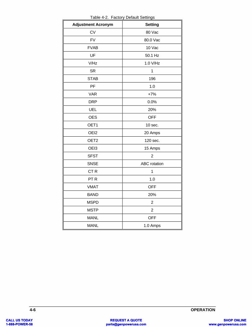
The sub-paragraphs below describe each adjustment that can be made to the DECS from its frontpanel. Refer to Table 4-1 for the display acronyms that will be displayed when each adjustment isselected. Table 4-2 lists the factory default settings for each adjustment. To access the AdjustmentMenu, proceed as follows:
1. Press the front panel SELECT button until MENU is displayed in the alphanumeric display.
2. Press the front panel UP button to display MENU 1.
3. Press the front panel SELECT button to access the various adjustable features as describedbelow.
4. After each adjustment is complete, press SELECT once more to save the new setting in memoryand to progress to the next adjustment.
COARSE VOLTAGE Adjustment (CV)
To select the Coarse Voltage Adjustment, press the front panel SELECT button until the acronym CVappears in the front panel display. Each up or down adjustment will increase or decrease the sensedgenerator output voltage by 6.0 Vac. The maximum range of the Coarse Voltage Adjust is from 0 to660 Vac.
CALL US TODAY 1-888-POWER-58
REQUEST A QUOTE [email protected]
SHOP ONLINE www.genpowerusa.com
CALL US TODAY 1-888-POWER-58
REQUEST A QUOTE [email protected]
SHOP ONLINE www.genpowerusa.com

4-4 OPERATION
FINE VOLTAGE Adjustment (FV)
To select the Fine Voltage Adjustment, press the front panel SELECT button until the acronym FVappears in the front panel display. Each up or down adjustment of the Fine Voltage Adjust willincrease or decrease the sensed generator output voltage by 0.5 Vac. The range of the Fine VoltageAdjust is ±60 Vac. Thus, the total range is 120 Vac from minimum to maximum of the sensed voltage.
FINE VOLTAGE ADJUST BAND (FVAB)
This adjustment is accessed similarly through the front panel, and is provided to allow the customer toestablish his preferred upper and lower boundaries around the Fine Voltage Adjust setpoint. Theintention is to limit the range of adjustment about a selected setpoint. It is also used for the upper andlower boundaries of the voltage correction of the VAR and PF controller. The adjustment's range isfrom 6 to 60 in integer steps. It may be necessary to adjust the Fine Voltage setpoint to realize thepreferred upper and lower boundaries.
A setting of "12" means that the band has a range of ±12 Volts around the generator voltage setpoint.
For example: Generator Voltage: 120 Vac
FVAB: 12Max. Voltage: 132 VacMin. Voltage: 108 Vac
MANUAL MODE SWITCH
This feature enables/disables the manual mode of control. When in the manual mode, the operatormust adjust excitation for any load variations on the generator.
To enable the manual mode, press the SELECT button until the MANL appears on the front panel.The display will indicate if the manual mode is ON or OFF. Use the UP or DOWN buttons until theproper condition is obtained.
WARNING
The manual mode excitation level must be evaluated prior to enabling this feature. If thelevel of excitation current is inappropriate for the generator loading, severe damage tothe generator may occur.
MANUAL MODE SETPOINT
To select the level of excitation current in the manual mode, press the select button until MANLappears on the front panel. Use the UP or DOWN buttons to obtain the appropriate level of excitation.The range of this mode is from 0 to 25 Amps dc. Care must be taken not to exceed 15 Amps on acontinuous basis and 20 Amps dc for more than 20 seconds. Damage to the DECS unit or thegenerator may occur if excitation levels are exceeded for any period of time.
UNDERFREQUENCY (UF)
The Underfrequency adjustment changes the frequency at which the DECS begins to operate on aconstant volts/Hertz ramp. The adjustment range is from 40 to 65 Hertz. Increasing the adjustmentwill increase (raise) the transition frequency in 0.1 Hz steps. Decreasing the adjustment will decrease(lower) the transition frequency in 0.1 Hz steps. To select the Underfrequency adjustment, press thefront panel SELECT button until the acronym UF appears on the front panel display. The display willalso indicate the current transition level in Hertz. If another transition level is desired, press the frontpanel UP or DOWN buttons until the desired level is attained.
VOLTS PER HERTZ SLOPE (V/Hz)
This adjustment allows the user to set the slope of the Volts per Hertz line of the DECS. The range ofV/Hz adjustment is from 0.0 to 3.0 per unit V/Hz in 0.1 per unit V/Hz steps.
CALL US TODAY 1-888-POWER-58
REQUEST A QUOTE [email protected]
SHOP ONLINE www.genpowerusa.com
CALL US TODAY 1-888-POWER-58
REQUEST A QUOTE [email protected]
SHOP ONLINE www.genpowerusa.com

OPERATION 4-5
STABILITY RANGE SELECT (SR)
The first step in acquiring stable generator output is to select the appropriate stability range, or"stability network", for the frame size of the generator and the excitation system used. A guide forselecting the Stability Range setting is provided by Table 4-3. By successively pressing the SELECTbutton on the front panel, SR will be displayed. With every push of the UP or DOWN buttons, thestability range setting can be changed. After selecting a stability range, the DECS will automaticallyload a preset stability level that should be acceptable for most applications.
STABILITY LEVEL ADJUSTMENT (STAB)
Adjusting the stability level within each stability range up or down will increase or decreaserespectively the gain of the DECS, which, in turn, will increase or decrease the response time of thesystem. Adjusting the stability level is analogous to "turning a stability potentiometer" in aconventional voltage regulator. This adjustment is the fine gain adjustment of the DECS unit, andallows the user to modify the stability to suit his specific needs. A higher value of STAB gives a morestable performance along with a more sluggish response than would a lower value of STAB. STABhas a scaled range of 0 (least stable/fastest response) to 250 (most stable/slowest response).
To select the Stability Level Adjustment, press the SELECT button until STAB appears on the frontpanel display. The display will indicate the present relative level of stability. If another level is desired,press the front panel UP or DOWN buttons until the proper level is attained.
Instability is best observed by monitoring the generator output voltage. Do not try to monitor the DCfield voltage. Even when the generator output voltage is stable, a DC voltmeter will show smallfluctuations in the field voltage. If instability is seen in the generator output, proceed as follows:
a. Operate the generator under no-load conditions.
b. Select an appropriate stability range (SR) for the generator being tested. Refer to Table 4-3.
c. Adjust the Stability Level (STAB) as required that provides acceptable no-load stability.
d. Apply load. If the generator remains stable and the system response is acceptable, no furtheradjustment is needed. If the generator is still unstable, increase the Stability Level by pressing theUP button until satisfactory stability is attained.
e. Reject and apply the load one or two more times. The generator should remain stable.
f. If the generator is not stable, or if the system response time is too slow, then adjust the stabilitylevel one or two increments at a time. Apply and reject the load after each adjustment untiloptimum performance is achieved.
g. If the generator is still unstable, recheck the appropriateness of the selected Stability Range(SR) and reselect if required. Retest any adjustments.
h. If the generator is still unstable and every other stability-bearing variable has been verified,then a custom stability range may be required. Call the factory, and order Basler Electric P/N: 92745 00 101, "DECS Communication Interface Module" (DCIM), to facilitate establishing anapplication-specific stability range.
CALL US TODAY 1-888-POWER-58
REQUEST A QUOTE [email protected]
SHOP ONLINE www.genpowerusa.com
CALL US TODAY 1-888-POWER-58
REQUEST A QUOTE [email protected]
SHOP ONLINE www.genpowerusa.com
4-6 OPERATION
Table 4-2. Factory Default Settings
Adjustment Acronym Setting
CV 80 Vac
FV 80.0 Vac
FVAB 10 Vac
UF 50.1 Hz
V/Hz 1.0 V/Hz
SR 1
STAB 196
PF 1.0
VAR +7%
DRP 0.0%
UEL 20%
OES OFF
OET1 10 sec.
OEI2 20 Amps
OET2 120 sec.
OEI3 15 Amps
SFST 2
SNSE ABC rotation
CT R 1
PT R 1.0
VMAT OFF
BAND 20%
MSPD 2
MSTP 2
MANL OFF
MANL 1.0 Amps
CALL US TODAY 1-888-POWER-58
REQUEST A QUOTE [email protected]
SHOP ONLINE www.genpowerusa.com
CALL US TODAY 1-888-POWER-58
REQUEST A QUOTE [email protected]
SHOP ONLINE www.genpowerusa.com

OPERATION 4-7
Table 4-3. Stability Range Settings ForDECS As Accessed Through The Front Panel
GeneratorSize
Generator Data StabilityRange
Gen. OpenCircuit Time
Constant(T'dO)
Gen. ExciterTime
Constant(Texc)
GeneratorFrequency
Small 1.0 Seconds 0.17 Seconds 50 Hz 0
1.0 Seconds 0.17 Seconds 60 Hz 1
1.5 Seconds 0.25 Seconds 50 Hz 2
1.5 Seconds 0.25 Seconds 60 Hz 3
2.0 Seconds 0.33 Seconds 50 Hz 4
2.0 Seconds 0.33 Seconds 60 Hz 5
2.5 Seconds 0.42 Seconds 50 Hz 6
2.5 Seconds 0.42 Seconds 60 Hz 7
3.0 Seconds 0.50 Seconds 50 Hz 8
3.0 Seconds 0.50 Seconds 60 Hz 9
3.5 Seconds 0.58 Seconds 50 Hz 10
3.5 Seconds 0.58 Seconds 60 Hz 11
4.0 Seconds 0.67 Seconds 50 Hz 12
4.0 Seconds 0.67 Seconds 60 Hz 13
5.0 Seconds 0.83 Seconds 50 Hz 14
5.0 Seconds 0.83 Seconds 60 Hz 15
5.5 Seconds 0.92 Seconds 50 Hz 16
5.5 Seconds 0.92 Seconds 60 Hz 17
6.0 Seconds 1.00 Seconds 50 Hz 18
Large 6.0 Seconds 1.00 Seconds 60 Hz 19
CALL US TODAY 1-888-POWER-58
REQUEST A QUOTE [email protected]
SHOP ONLINE www.genpowerusa.com
CALL US TODAY 1-888-POWER-58
REQUEST A QUOTE [email protected]
SHOP ONLINE www.genpowerusa.com

4-8 OPERATION
(OPTIONAL) VAR/POWER FACTOR ADJUSTMENTS (VAR or PF)
The VAR/PF is an optional feature and is used when paralleling a generator to a utility. It is onlyavailable with models DECS 32/63/125-15-BXX. If it has not been purchased, it cannot be selected.The PF range is from -0.6 to +0.5 in 0.01 steps. A -0.8 Power Factor setting means that the generatoris set to operate at a 0.8 leading (underexcited) power factor condition. A +0.8 Power Factor settingmeans the generator is set to operate at a 0.8 lagging (overexcited) power factor condition.
The VAR adjustment affects the Volt Amp Reactive power setpoint. The range is from -100 to 0 to100% of the 1 Amp C.T. input to the DECS unit. It is adjustable in integer steps. If the DECS receivesa 1 Amp C.T. signal from the phase B C.T., and the VAR setpoint is at +100, then the DECS would beexporting 100% reactive power (Var's). A setpoint of -100 indicates the DECS would be importingVAR's.
Increasing the level of VARs or the PF will increase the amount of field excitation. Conversely,decreasing the level of VARs or the PF will decrease the amount of field excitation.
The VAR/PF feature has two states: (a) Inactive. The feature is available, but is disabled by shortinga set of contacts across terminals 52J and 52K. (b) Active. The feature is available and active whenterminals 52J and 52K are not shorted.
Table 4-4.
Operation Mode 52 J-K 52 L-M
Droop Mode Active closed open
Voltage Mode Active, NO DROOP, NO VAR/PF closed closed
VAR/PF Active open closed
VAR/PF Active (version 1.4.4 or later)* open open
* This mode is not allowed for versions 1.4.3 or earlier. For versions 2.0.5 or later, it is recommendedthat Droop Mode be active when VAR/PF is active.
To select VAR or PF control adjustment, press the front panel SELECT button until the desiredadjustment acronym is displayed. The display will also indicate whether the feature is active (ON orOFF), and the relative level of adjustment present. If another level is desired, press the UP or DOWNbuttons until the desired setting is acquired.
DROOP ADJUSTMENT (DRP)
The Droop Adjustment is used when paralleling generators. The settings range from 0% to 20%droop in 0.5% steps. Increasing the DRP level will increase the amount of generator voltage droopwith the application of a reactive load. A 1 or 5 amp signal from a 1 or 5 VA, 5P5 current transformer(CT) into DECS terminals CTB1 and CTB2 will give approximately a 20% voltage droop with theapplication of a 0 PF load and the DRP adjustment level set to maximum.
CALL US TODAY 1-888-POWER-58
REQUEST A QUOTE [email protected]
SHOP ONLINE www.genpowerusa.com
CALL US TODAY 1-888-POWER-58
REQUEST A QUOTE [email protected]
SHOP ONLINE www.genpowerusa.com

OPERATION 4-9
Figure 4-2. % GENERATOR DROOP VS DROOP SETTING AT DIFFERENTPOWER FACTOR LOADS
The DRP feature has two states: (a) Inactive. The feature is available, but is disabled by shorting aset of contacts across terminals 52L and 52M. (b) Active. The feature is available and is active whenterminals 52L and 52M are not shorted. Refer to Table 4-4 for other input connection considerations.
To select the Droop adjustment, press the front panel SELECT button until DRP appears on the frontpanel display along with the present, relative droop level. If another level of droop is desired, pressthe front panel UP or DOWN buttons until the desired level is acquired.
The best method of setting the droop level is to first operate each generator individually (non-paralleled) and apply rated or near-rated current at a +0.8 PF. The amount of droop for eachgenerator can be set based upon the instruction above. An alternate method of setting the droop is asfollows:
a. Ensure the prime mover is stopped and that all power is off before proceeding any further.
b. With the droop CT installed into the generator Phase B lead, temporarily connect the generatorE1 sensing lead to the generator Phase B lead. Connect the E2 and E3 sensing leads to generatorPhase A lead.
c. Operate each generator individually (non-paralleled) and apply rated or near-rated load at unity(1.0) PF. The amount of droop can then be set by adjusting the Droop adjustment as needed for theapplication.
d. If, when adjusting the generator droop, the generator output voltage does not decrease with theapplication of load, recheck the CT polarity and the sensing lead connections.
e. After completing the droop adjustments, reconnect the DECS sensing leads to the appropriateconfiguration as determined by one of the interconnect diagrams on Figures 3-7 through 3-10.
When the generators are operated in parallel, they will share the load equally. If no reactive load ispresent, the generator voltage should not droop. If it does droop, recheck the sensing connections,the CT connections, and CT polarity. If needed, repeat the adjustment procedure.
For cross current or reactive differential compensation, a series resistor must be used for propercurrent sharing. (See Figure 3-12.)
CALL US TODAY 1-888-POWER-58
REQUEST A QUOTE [email protected]
SHOP ONLINE www.genpowerusa.com
CALL US TODAY 1-888-POWER-58
REQUEST A QUOTE [email protected]
SHOP ONLINE www.genpowerusa.com
4-10 OPERATION
OPTIONAL UNDEREXCITATION LIMITING/OVEREXCITATION LIMITING (UEL/OEL)
The Over and Under Excitation limiters will establish and maintain a safe level of excitation for thegenerator. They will not allow the excitation to drop to a level where the generator could slip out ofsynchronization nor will they allow the generator to be overexcited to the point of damaging thegenerator field windings.
CAUTION
For versions 1.6.0 or earlier, when UEL is used, auto ranging of the sensing inputmust be disabled via DCIM interface.
The adjustable level of reactive current, for the Under Excitation Limiter, is from 1 to 80% of themaximum reactive current rating of the generator. The UEL is only active while in the DROOP, PF orVAR mode. The front panel UEL LED will illuminate whenever the reactive current exceeds theprogrammed level. When the reactive current decreases below the programmed level, the UEL LEDwill extinguish. To adjust the UEL setpoint, press the front panel SELECT button until the UELacronym appears in the display. Subsequent presses of the UP or DOWN buttons will adjust the pointat which the UEL activates.
The Over Excitation Limiter has three regions of operation. Refer to Figure 1-3. Region 1 is fixed at amaximum of 30 Adc. The timing for this region starts anytime the current level of OEI3 is exceeded.The timing is adjustable in Region 1 by the OET1 setting. OET1 is adjustable from 0 to 10 seconds.Once OET1 expires, the dc excitation current is driven down to the level as set by OEI2.
The time delay for Region 2 is adjustable by OET2. This adjustment is from 0 to 120 seconds, startingupon the expiration of OET1. The current level of Region 2 is set by OEI2. This is adjustable from 1to 20 Adc. If the dc current level exceeds the OEI2 setting and remains there until OET2 expires, thenthe dc current is driven down to the level as set by OEI3.
The dc excitation current will remain at the level of OEI3 continuously until the fault is cleared byexternal means. OEI3 is adjustable from 1 to 15 Adc.
Overexcitation current limiting will occur whenever OEI3 is exceeded, which is indicated by the frontpanel OEL LED illuminating. The OEL action will halt once the field current drops 1 Amp below thefield current limiting setpoint. To adjust the OEI/OET setpoints, press the front panel SELECT buttonuntil the appropriate acronym appears on the front panel display along with its present relativesetpoint. Subsequent presses of the UP or DOWN buttons will adjust the setpoint value.2
(OPTIONAL) OVEREXCITATION SELECT (OES)
This optional feature is integral with the OEL feature and allows the user to enable or disable the OEL."Enabled" is indicated with a "1", and "disabled" is indicated with a "0". To change the state of OES,press the front panel select button until the acronym OES appears on the front panel display. Bypressing the UP or DOWN buttons, the state can be toggled.
SOFTSTART (SFST)
The DECS provides the user the opportunity to set how fast the DECS unit will bring up thegenerator's voltage to the "generator voltage setting". The scaled range of adjustment is from "0",which will be the slowest rate of voltage build-up, to "99", which will be the fastest. To adjust thesoftstart rate, press the SELECT button until the acronym SFST appears on the front panel display.Subsequent presses of the UP or DOWN buttons will adjust the softstart rate to the desired setting.
DECS SENSING CONFIGURATION (SNSE)
This adjustment allows the user to configure the DECS for either single- or three-phase sensing. Thefactory default setting is for three-phase sensing with A-B-C rotation. However, the user can select A-C-B rotation as well as single-phase sensing. When selecting single-phase sensing, inputs E2 and E3must be connected to Phase C of the generator output. (Refer to Figures 3-9, 3-10 for single-phase
CALL US TODAY 1-888-POWER-58
REQUEST A QUOTE [email protected]
SHOP ONLINE www.genpowerusa.com
CALL US TODAY 1-888-POWER-58
REQUEST A QUOTE [email protected]
SHOP ONLINE www.genpowerusa.com

OPERATION 4-11
sensing interconnection.) Single-phase sensing has been selected when "A-C" is displayed on thefront panel display.
To access this adjustment, press the SELECT button until the acronym SNSE appears on the frontpanel display. Subsequent presses of the UP or DOWN buttons will change the setting from ABC toACB to A-C. Once the desired sensing configuration has been selected, press the SELECT buttononce more to save the setting in memory.
CURRENT TRANSFORMER PRIMARY RATNG(CT R)
This adjustment allows the user to set the current transformer primary rating. It has a range from 1 to5000 in single integer steps. As an example, if the DECS is style DECS XX-15-XXX1-VXX and thesystem current transformer steps the current down from 200 A to 1 A,then the current transformerprimary rating should be set to 200. Similarily, if the DECS is style DECS XX-15-XXX5-VXX and thesystem current transformer steps the current down from 200 A to 5 A, then the current transformerprimary rating should be set to 200. To access this adjustment, press the SELECT button until theacronym CT R is displayed on the front panel. To adjust the setting, press the UP or DOWN buttonsuntil the desired setting has been acquired.
SENSING POTENTIAL TRANSFORMER RATIO (PT R)
This adjustment allows the user to set the sensing transformer ratio. It has a range of adjustmentfrom 0.1 to 99.9 in 0.1 steps and 100 to 200 in 1.0 steps. It is used so that the displayed voltage ofthe DECS will match the actual generator output voltage. For example, if the system has a sensingpotential transformer that steps the voltage down from 3300 Vac to 100 Vac, then the sensingpotential transformer ratio (PT R) should be set to 33.0. To access this adjustment, press theSELECT button until the acronym PT R is displayed on the front panel. To adjust the setting, pressthe UP or DOWN buttons until the desired setting has been acquired.
VOLTAGE MATCHING (VMAT)
This feature is used to control the generator output prior to implementing conventional generator-to-utility synchronizing procedures. The VMAT option compares the generator and utility bus voltages,adjusts the generator output and once the voltages are within 1% of each other, then the VMATCHLED illuminates; thereby indicating to the user that he may commence synchronizing procedures. Toenable the Voltage Matching option, press the SELECT button until the VMAT acronym appears onthe front panel display. The factory default setting is OFF. By pressing the UP or DOWN buttons, thefeature can be enabled (ON) or disabled (OFF).
VOLTAGE MATCHING BAND (BAND)
This feature is used to set a band about the generator voltage setpoint within which the voltagematching feature will operate. The band width is adjustable with a range from 1% to 20% in 1% steps.For example, if the generator voltage setpoint is 120 Vac and the user sets the BAND value at 10,then the band limits are set at 10% above and 10% below 120 Vac. The upper limit would then be at132 Vac, and the lower limit would be at 108 Vac with a nominal setpoint of 120 Vac. If the voltage atthe DECS BUS1 and BUS3 inputs is outside of this band, then the VOLTAGE MATCHING feature willnot operate. To access this adjustable feature, press the SELECT button until the acronym BANDappears on the front panel display. Subsequent presses of the UP or DOWN buttons will allow theuser to set the desired band limits.
VOLTAGE MATCHING SPEED (MSPD)
This adjustable feature is used to set the speed of the VMAT feature and has a scaled range from 1 to20 in integer steps. A setting of 1 provides the slowest speed while a setting of 20 is the fastest. Toaccess this adjustment, press the SELECT button until the acronym MSPD appears on the front paneldisplay. Subsequent presses of the UP or DOWN buttons allows the user to set MSPD value. Thefactory default setting is at 20.
CALL US TODAY 1-888-POWER-58
REQUEST A QUOTE [email protected]
SHOP ONLINE www.genpowerusa.com
CALL US TODAY 1-888-POWER-58
REQUEST A QUOTE [email protected]
SHOP ONLINE www.genpowerusa.com

4-12 OPERATION
VOLTAGE MATCHING STEP (MSTP)
This adjustable feature is used to set the size of the correction step in voltage matching mode. Therange of this adjustment is from 1 to 8 in integer steps. A setting of 1 will provide voltage correction in0.5 V steps. Similarly, a setting of 8 will provide 4.0 V steps. To access this adjustment, press theSELECT button until the acronym MSTP is displayed on the front panel. Subsequent presses of theUP or DOWN buttons will allow the user to determine his step setting.
FRONT PANEL OPERATION
There are 4 parts to the DECS front panel:
• Nine status and diagnostic LED's provide continuous information about the operation of theDECS unit.
• A 4-character alphanumeric display is used for display and adjustments/set-up.• A 3-button keypad allows for the selection of information to be displayed and entering of
adjustments.• A serial data link connection provides for computerized factory testing and field
troubleshooting by Basler-trained engineers and technicians. It also provides a means toconnect the DCIM for tuning various parameters for unique generator applications.
STATUS AND DIAGNOSTIC LED'S.
Alarm LED. The front panel red ALARM LED shows the status of the solid state Alarm Output triac.Small (0.15 Amp) AC and DC loads can be connected to this triac at the "ALRM+" and "ALRM-"terminals on the DECS unit.
Both hardware and software protective features control the Alarm triac operation. Overexcitationhardware in the DECS unit will turn on the Alarm Relay when generator field voltage exceeds a levelpreset in hardware for 15 seconds. Refer to Table 4-5.
Table 4-5. Overexcitation Presets
DECS Model Number Voltage Trip Point
DECS 32-15 50
DECS 63-15 100
DECS 125-15 200
If the field voltage returns to a level below the voltage trip point preset in hardware, then the 15second timer will reset to zero.
OVEREXC LED. The red Overexcitation LED is turned on when the observed field voltage exceedsa factory preset value (Refer to Table 4-5). Should the overexcitation condition least for 15 seconds,then the Alarm Relay and the front panel ALARM LED will be turned on.
OVERVOLT LED. The red Overvoltage LED is turned on whenever the generator output voltageexceeds 135%. If this overvoltage condition continues for 0.75 seconds, then the Alarm triac and thefront panel ALARM LED will be turned on.
OVERTEMP LED. The red Overtemperature LED is turned on when the observed temperature ofthe power semiconductors exceeds a set limit. The DECS unit will also turn on the Alarm Relay andthe front panel ALARM LED.
UF LED. The yellow Underfrequency LED displays the state of the underfrequency feature of theDECS unit. When the generator frequency falls below the underfrequency setpoint, the LED is turnedon and the underfrequency features is activated.
MANUAL LED. This red LED will be illuminated anytime the manual excitation mode is enabled.
CALL US TODAY 1-888-POWER-58
REQUEST A QUOTE [email protected]
SHOP ONLINE www.genpowerusa.com
CALL US TODAY 1-888-POWER-58
REQUEST A QUOTE [email protected]
SHOP ONLINE www.genpowerusa.com
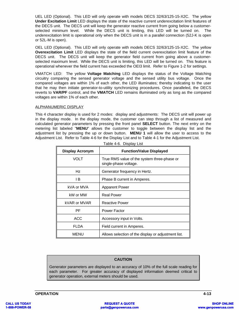
OPERATION 4-13
UEL LED (Optional). This LED will only operate with models DECS 32/63/125-15-X2C. The yellowUnder Excitation Limit LED displays the state of the reactive current underexcitation limit features ofthe DECS unit. The DECS unit will keep the generator reactive current from going below a customer-selected minimum level. While the DECS unit is limiting, this LED will be turned on. Theunderexcitation limit is operational only when the DECS unit is in a parallel connection (52J-K is openor 52L-M is open).
OEL LED (Optional). This LED will only operate with models DECS 32/63/125-15-X2C. The yellowOverexcitation Limit LED displays the state of the field current overexcitation limit feature of theDECS unit. The DECS unit will keep the generator field current from going above a customer-selected maximum level. While the DECS unit is limiting, this LED will be turned on. This feature isoperational whenever the field current has exceeded the OEI3 limit. Refer to Figure 1-2 for settings.
VMATCH LED: The yellow Voltage Matching LED displays the status of the Voltage Matchingcircuitry comparing the sensed generator voltage and the sensed utility bus voltage. Once thecompared voltages are within 1% of each other, the LED illuminates; thereby indicating to the userthat he may then initiate generator-to-utility synchronizing procedures. Once paralleled, the DECSreverts to VAR/PF control, and the VMATCH LED remains illuminated only as long as the comparedvoltages are within 1% of each other.
ALPHANUMERIC DISPLAY
This 4 character display is used for 2 modes: display and adjustments: The DECS unit will power upin the display mode. In the display mode, the customer can step through a list of measured andcalculated generator parameters by pressing the front panel SELECT button. The next entry on themetering list labeled "MENU" allows the customer to toggle between the display list and theadjustment list by pressing the up or down button. MENU 1 will allow the user to access to theAdjustment List. Refer to Table 4-6 for the Display List and to Table 4-1 for the Adjustment List.
Table 4-6. Display List
Display Acronym Function/Value Displayed
VOLT True RMS value of the system three-phase orsingle-phase voltage.
Hz Generator frequency in Hertz.
I B Phase B current in Amperes.
kVA or MVA Apparent Power
kW or MW Real Power
kVAR or MVAR Reactive Power
PF Power Factor
ACC Accessory input in Volts.
FLDA Field current in Amperes.
MENU Allows selection of the display or adjustment list.
CAUTION
Generator parameters are displayed to an accuracy of 10% of the full scale reading foreach parameter. For greater accuracy of displayed information deemed critical togenerator operation, external meters should be used.
CALL US TODAY 1-888-POWER-58
REQUEST A QUOTE [email protected]
SHOP ONLINE www.genpowerusa.com
CALL US TODAY 1-888-POWER-58
REQUEST A QUOTE [email protected]
SHOP ONLINE www.genpowerusa.com

4-14 OPERATION
DECS COMMUNICATION INTERFACE MODULE (DCIM) AVAILABLEFEATURES
Optional communications software is available to aid in the calibration and configuration of the DECSunit. There are three available assemblies for the DCIM. Each assembly includes an interface module(P/N 9 2745 03 100) and software diskette.
1. 9 2745 00 101 (DECS15-DOS)2. 9 2745 00 102 (DECS15-Windows 3.1)3. 9 2745 00 103 (DECS 15-Windows 95)
The DCIM is not powered from the DECS and contains a 9V battery for operating power. The DCIM isrequired to select or adjust the following DECS features:
• Loss of Sensing Timing• UEL Enable• Range Select (Sensing)• Fine Voltage Adjust Speed• Generator Overvoltage Setting• AVR Gain: Custom Gain Settings for KP, KI, KD, Scale Factor• VAR/PF/OEL/UEL: Discrete KP and KI settings for each function• PWM Start• Step Responses• Metering
If you have a DCIM and would prefer a different operating software, the following software is availableindividually:
BESTCOMS-DECS15-DOSBESTCOMS-DECS15-16 (For Windows 3.1 Users)BESTCOMS-DECS15-32 (For Windows 95 Users)
DECS ALARM ENABLE/DISABLE
The DECS has been designed to provide an alarm indication and a triac closure for each of thefollowing trouble conditions:
• Overtemperature of the DECS• Overvoltage• Overexcitation• Underfrequency
The triac has been provided to allow the user to customize these alarm functions to suit his specificneeds; such as remote alarm annunciation or various system relay trips.
The Overtemperature, Overvoltage, and Overexcitation alarm functions are factory preset and areenabled. The Underfrequency alarm function is disabled as shipped from the factory, but each andevery alarm feature can be enabled or disabled by the customer if he chooses via the optional DECSCommunication Interface Module (DCIM) and his IBM-compatible (386 or better) personal computer.
DECS SHUTDOWN ENABLE/DISABLE
The DECS has been designed with inherent protective features that, if enabled, will shutdown theDECS field output and, hence, the excitation system. The trouble conditions monitored are identical tothose for the DECS Alarm conditions:
• Overtemperature of the DECS• Overvoltage• Overexcitation• Underfrequency
To allow the customer the greatest in flexibility, none of the above shutdown conditions are enabledfrom the factory. As is the case for the Alarm conditions, the customer can tailor these shutdownfeatures to meet his specific needs via the optional DECS Communication Interface Module (DCIM)
CALL US TODAY 1-888-POWER-58
REQUEST A QUOTE [email protected]
SHOP ONLINE www.genpowerusa.com
CALL US TODAY 1-888-POWER-58
REQUEST A QUOTE [email protected]
SHOP ONLINE www.genpowerusa.com

OPERATION 4-15
and an IBM-compatible (386 or better) personal computer. The shutdown conditions, if activated, arecleared and reset only if power to the DECS is cycled.
CALL US TODAY 1-888-POWER-58
REQUEST A QUOTE [email protected]
SHOP ONLINE www.genpowerusa.com
CALL US TODAY 1-888-POWER-58
REQUEST A QUOTE [email protected]
SHOP ONLINE www.genpowerusa.com

CALL US TO1-888-POWECALL US TO1-888-POWE
DCIM DOS COMMUNICATIONS 5-1
SECTION 5 • DCIM DOS COMMUNICATIONS
INTRODUCTION
This section describes the installation and usage of the optional DECS Communication InterfaceModule (DCIM) using DOS communications. The DCIM (Figure 5-1) is used in association with theDigital Excitation Control System (DECS) Models: DECSXXX-15-XXX. The DCIM requires an IBMcompatible personal computer to run the DCOM15 software that communicates with the DECS unit.
HARDWARE SPECIFICATIONS
A list of the auxiliary components needed to communicate with the DECS, using the DCIM, is shownbelow:
• DCIM (DECS Communication Interface Module)*NOTE: The DCIM contains a 9V battery.
• Minimum Requirements for Computer:
1. 80386, IBM Compatible with MSDOS, Version 3.0 or higher.
2. Nine Pin Serial Port. If only a 25 pin serial port is available, then a 9 pin to 25 pin adapter isrequired.
3. 3.5 inch, Low Density Floppy Drive.
NOTEHard drive is not required for operation of DCOM15 software.
• DCIM Software Diskette with DCOM15.EXE (DECS interface software), PID2.EXE (StabilityParameter Generation Software), and INSTALL.BAT files.
The following paragraphs describe the required interconnection and the software installation procedure.
Figure 5-1. DECS Communication Interface Module
DAY R-58
REQUEST A QUOTE [email protected]
SHOP ONLINE www.genpowerusa.com
DAY R-58
REQUEST A QUOTE [email protected]
SHOP ONLINE www.genpowerusa.com

5-2 DCIM DOS COMMUNICATIONS
DCIM INTERCONNECTION
The DCIM must be connected to the DECS unit and also to the personal computer so that the DCOM15software can establish the serial communication link to the DECS. The DECS unit must be powered upwith rated input voltage. The actual Serial interface interconnection scheme is shown in Figure 5-2.
Figure 5-2. DECS and DCIM Interconnection 1
DCIM SOFTWARE INSTALLATION
In order to utilize the DECS interface software, the file DCOM15.EXE and PID2.EXE should beinstalled on the Personal Computer. Retrieve the DCIM software diskette located at the rear of thismanual (see Figure 2) and insert it into the 3-1/2 disk drive. Type the following keystrokes to install:
(floppy drive designator, e.g. B:) [Enter]
INSTALL (Hard drive designator, e.g. C:) [Enter]
At this point, the directory C:\DECS-15 has been created and the DCIM software files installed in thatdirectory. Verify installation by now typing DIR C:\DECS-15 (Enter).
NOTEThe DCIM software "DCOM15" has been designed to work with all versions of 15 AmpDECS. Before executing the interface software, review the README.TXT file now inthe C:\DECS-15 directory for further detail on these operational variations.
To run the program from either the hard drive or the floppy drive, type the following keystrokes:
(floppy drive designator e.g. B:\) [ENTER]
OR (hard drive designator e.g. C:\) [ENTER]
CD \DECS-15 [ENTER]
DCOM15 [ENTER]
The DCOM15 software defaults to using COM1 for connecting to the DECS. To select COM2append a 2 after the DCOM15 command.
i.e. DCOM15 2 [ENTER]
This should execute the communications interface software.
CALL US TODAY 1-888-POWER-58
REQUEST A QUOTE [email protected]
SHOP ONLINE www.genpowerusa.com
CALL US TODAY 1-888-POWER-58
REQUEST A QUOTE [email protected]
SHOP ONLINE www.genpowerusa.com

DCIM DOS COMMUNICATIONS 5-3
Welcome to DCOM15.EXE the Friendly interface software package for the DigitalExcitation Control System (DECS). The program provides the user acommunication link to the DECS via the DECS Interface Communication Module(DCIM).
Program developed byBasler Electric Co.
Highland, Illinois 62249Phone: 618-654-2341
Press any key to continue
MAIN MENU USAGE
After pressing any key on the keyboard, the DCOM15 Main Menu should appear on the display. Thismenu provides all the available menu selections for interfacing to the DECS unit. The main menu isshown below:
DCIM SOFTWARE FOR VOLTAGE MATCHING
15 AMPS DECS VERSION X.X
LINK ADJUST HELP FILE QUIT OPTION F10-Menu
*** Real-Time mode is disabled.***
Use ALT-H to see help window.
The main menu command line lets the user select the following menus:
LINK Establishes serial communications link to the DECS.
ADJUST Provides access to DECS internal adjustments.
HELP This is the DCOM15 software help file.
FILE This command allows the transfer of the DECS internal adjustments to the hard drive ofthe computer. It also allows transfer from a file on the hard drive of the computer to thememory of the DECS unit.
QUIT This command breaks the serial communications link and exits the DCOM15 software.
OPTION This command allows the user to customize the DECS Alarm settings. It also allowsthe user to select for what condition causes the DECS to power down the field output.
From this screen, the user can select the appropriate menu by simultaneously pressing the ALT key andthe first letter of the menu selection. For example, if the user wanted to establish the serial link to theDECS, he could press ALT and L keys at the same time. The command line can also be accessed bypressing the F10 key only. When this key is pressed, the cursor will enter the command line and theuser can arrow to the appropriate menu. The user then presses Enter, and that menu will be accessed.
SUCCESSFUL LINK MESSAGE
When the ALT key and the L key are pressed at the same time, the decscom software establishes acommunication link to the DCOM15 unit. If the communications link was established successfully, thenthe following message should be displayed on the computer screen:
*** LINK to DECS SUCCESSFUL ***
After a successful connection, any of the available menus can be accessed from the Main Menu screen.Additional attempts to establish communication link will display the following message on the computerscreen:
*** STILL ACTIVE ***
CALL US TODAY 1-888-POWER-58
REQUEST A QUOTE [email protected]
SHOP ONLINE www.genpowerusa.com
CALL US TODAY 1-888-POWER-58
REQUEST A QUOTE [email protected]
SHOP ONLINE www.genpowerusa.com

5-4 DCIM DOS COMMUNICATIONS
INTERFACE PROBLEM SCREEN
If the serial link connection to the DECS is not established, then an Interface Problem Screen willappear. This screen directs the user to check the serial connection to the DECS. To help the userdiagnose his systems problem, refer to the following paragraphs, Troubleshooting Procedure. TheInterface Problem Screen is shown below:
*** LINK TO DECS FAILED ***
Check to make sure that the connector is plugged into the DECS. Is the DECS unit powered up? Is thecorrect port specified on the computer?
PRESS ANY KEY TO CONTINUE OR ESC TO CANCEL.
ADJUSTMENT MENU
The Adjustment Menu is accessed from the Main Menu by pressing at the same time, the Alt and Akeys on the keyboard of the P.C. It can also be accessed by pressing the F10 key to get to the MainMenu's command line, arrowing to the ADJUST item, and then pressing the Enter key. The followingwindow should appear on the screen of the P.C., depicting the present states of adjustment within theDECS:
DECS ADJUSTMENT WINDOW
READ EEPROM STEP_RESP QUIT TRANSFER MONITOR F10-Menu
Generator Voltage: 208.0 Volts VAR Switch: OFFRange Select: 3 VAR Setting: 0%
FVAB: 10 Var GAIN KP: 5FVAS: 3 PF Switch: OFF
Voltage Match Switch: OFF PF Setting: 0.99Voltage Match Band: 20 PF GAIN KP: 10
Voltage Match Speed: 2 Var/PF GAIN KI: 8Voltage Match Step: 2 Droop Setting: 20
Manual Switch: OFF UEL Setting: 20Manual Setting: 0.4 AMP UEL-Gain KP: 10
Under Frequency: 57.0 Hertz UEL-Gain KI: 7Volts per Hertz: 1.0 V/Hz OES Switch: ON
Soft Start Speed: 10 OET1 (High OE Timer): 10PWM Start: 15 OEI2 (Med. OE Level): 20
Phase Configuration: ABC OET2 (Med OE Timer): 20Current Xformer Rating: 200 OEI3 (Low. OE Level): 15
Sense Xformer Ratio: 1.0 OEL-Gain KP: 8Stability Range: 20 OEL-Gain KI: 10
PID: KP: 400 KI: 12 KD: 3546 SCALE: 7 STAB: 196
Definitions Of Top Menu Commands
Read/ALT-R command. This command reads all settings from the DECS unit into the Adjustmentwindow. You can use either the F10 command or the ALT-R keystroke. Use this command to bringall of the current settings of the DECS unit into the Adjustment window when the DECS unit is beingpowered up.
CALL US TODAY 1-888-POWER-58
REQUEST A QUOTE [email protected]
SHOP ONLINE www.genpowerusa.com
CALL US TODAY 1-888-POWER-58
REQUEST A QUOTE [email protected]
SHOP ONLINE www.genpowerusa.com

DCIM DOS COMMUNICATIONS 5-5
EEPROM/ALT-E command. This command directs the DECS unit to copy all the settings in memoryinto electrical erasable programmable memory (EEPROM). Once the EEPROM data is saved, it is innonvolatile memory and is not lost even if all power to the DECS unit is removed. Use this commandif you change any settings on the screen and want those setting changes to be the default settings.
STEP_RESP/ALT-S command. Once the command is executed, the Step Response windowappears in the middle of the screen. This command performs the 10% generator voltage stepchange by pressing the ENTER key. This is for analysis purposes. User can verify whether the PIDsetting is appropriate to get good dynamic performance or not. When you press the ESC key whilein the Step Response window, program control is returned to the adjustment Menu.
Quit/ALT-Q command. Executing this command closes the Adjustment window and returns to theMAIN window. It will automatically save all settings into EEPROM if any settings are changed.
TRANSFER/ALT-T. This command copies all the PID settings at the bottom of the screen into theuser PID settings. After transfer is completed, it allows the user to modify the PID setting. Notice thatthe Stability Range is automatically changed to 20.
MONITOR/ALT-M. This command creates a window that displays the existing generator parametersand the DECS protection status.
F10-Menu. Pressing the F10 key highlights the main menu READ command. Cursor arrow keystrokes select other main menu commands. Pressing the F10 key again toggles the function off.
Definitions Of Adjustments
NOTEThe acronyms listed with each adjustment definition are provided for reference to theDECS front panel display.
Generator Voltage (GV). This adjustment allows the user of the DECS to set the generator outputterminal voltage. It combines the adjustments of Coarse Voltage (CV) and Fine Voltage (FV) that areavailable from the DECS front panel. It will allow the user to select voltages from 0 to 660 Vac with aresolution of half volt steps.
Range Select. This adjustment sets the sensed voltage range which will be present on E1, E2 and E3.A Range Select setting of 0 will allow DECS to select its own range based on the voltage level enteredinto GV. Whenever the UEL option is used, a Range Select of 1, 2 or 3 should be selected as to thefollowing criteria,
(GV) Generator Set Point Range Select
0 - 170 1
170 - 300 2
300 - 600 3
This setting is only accessible through DCOM15.
Fine Voltage Adjustment Band (FVAB). This adjustment gives the user the ability to set an adjustableband around the generator output voltage. It is also used for the upper and lower boundaries of thevoltage correction from VAR and PF controller. It has a range of adjustment from 6 to 60 in integersteps. A setting of 12 means that the band has a range of ±12 volts around the generator voltage setpoint. The following example describes the use of FVAB:
Generator Voltage: 120FVAB: 12Generators Max Voltage = 132 VacGenerators Min Voltage = 108 Vac
It may be necessary to adjust the Fine Voltage setpoint to realize the preferred upper and lowerboundaries.
CALL US TODAY 1-888-POWER-58
REQUEST A QUOTE [email protected]
SHOP ONLINE www.genpowerusa.com
CALL US TODAY 1-888-POWER-58
REQUEST A QUOTE [email protected]
SHOP ONLINE www.genpowerusa.com
5-6 DCIM DOS COMMUNICATIONS
Fine Voltage Adjust Speed (FVAS). This feature allows the user to adjust the rate at which DECSincrements or decrements the operating setpoint (fine voltage, VAR, or PF) via the remote adjustterminals, 6U and 6D. This adjustment has a scaled range from 1 (slowest adjustment) to 7 (fastestadjustment). This feature is only accessible through the communications software.
Voltage Matching Switch (VMAT). This adjustment is used to enable or disable the voltage matchingfeature on the Voltage Matching DECS unit. A 0 disables the voltage matching feature, while a 1enables the voltage matching feature.
Voltage Matching Band (BAND). This adjustment is used to set a band in which the voltage matchingfeature will operate. The band is based on the generator output voltage set point. The range of thisadjustment is from 1 to 20 in integer steps. An example of how to set this is listed below:
Example: Generator Voltage: 120Voltage Matching Band: 10
This sets the band at 10% above and 10% below the generator set point of 120 Vac. The minimumlevel would be 108 Vac and the maximum level would be 132 Vac. If the voltage at the BUS1 & BUS3inputs of the Voltage Matching DECS is outside of this band, then voltage matching will not operate.
Voltage Matching Speed (MSPD). This adjustment is used to set the speed of the voltage matchingfeature. The range of this adjustment is from 1 to 20 in integer steps. A setting of a 1 is the slowestspeed while a setting of a 20 is the fastest speed.
Voltage Matching Step (MSTP). This adjustment is used to set the size of the correction step in voltagematching mode. The range of this adjustment is from 1 to 8 in integer steps. A setting of a 1 means thevoltage correction steps will be at 0.5 volt size. If the setting of an 8 is used, the voltage correction sizeis 4 volts.
Manual Switch (MANL). This adjustment allows the user to enable or disable manual control of theexciter field current. A 0 means that Manual Mode is disabled. A 1 means that Manual Mode isenabled. An enabled Manual Mode overrides all other modes of operation.
Manual Setting (MANL). This is the adjustment of the field current level during Manual Mode ofoperation. The field current level can be set from 0 to 25.0 Amps in 0.1 Amp steps. Whenever theManual Switch is set to 1, the field current level will immediately be driven to the setpoint level. Manualmode becomes active if the sensing voltage is lower than 25% of the generator terminal voltage formore than LOS time setting.
Under Frequency (UF). This adjustment allows the user to set the corner frequency point of the underfrequency curve. Because of the DECS ability to precisely read the generator's frequency, theresolution of this setting is in 0.1 Hz steps with a range of 40.0 to 65.0 Hz.
Volt Per Hertz (V/Hz). This adjustment allows the user to set the slope of the Volts/Hertz line of theDECS unit. It's allowable adjustment range is from 0.0 to 3.0 p.u. V/Hz. The resolution of this setting is in0.1 p.u. V/Hz steps (p.u. is defined as per unit).
Soft Start Speed (SFST). This adjustment lets the user set how fast the DECS unit will bring up thegenerator's voltage to the Generator Voltage setting. The range of this adjustment is from 0 to 99 ininteger steps. A setting of 0 will be the slowest speed, while a setting of 99 will be the fastest setting.The user should modify this setting based on his particular soft start requirements for his generatorsystem.
PWM-Start. This window gives the user the ability to adjust the initial start-up pulse width of the DECS'output to the field of the generator during the soft start sequence. The range of this adjustment is from 0to 15 integer steps. The default value is 15 which corresponds to an initial output width of 2.5% dutycycle.
Phase Configuration. This adjustment allows the user to define how the DECS will be implemented inhis generator system. The DECS sensing is adjustable in three different modes: Three Phase A-B-CRotation, Three Phase A-C-B Rotation, and Single Phase A-C Rotation. The adjustments are made bypressing the corresponding number key to select the sensing configuration. Pressing the Enter keysends this information to the control.
CALL US TODAY 1-888-POWER-58
REQUEST A QUOTE [email protected]
SHOP ONLINE www.genpowerusa.com
CALL US TODAY 1-888-POWER-58
REQUEST A QUOTE [email protected]
SHOP ONLINE www.genpowerusa.com

DCIM DOS COMMUNICATIONS 5-7
CAUTIONIt is important that the phase rotation and sensing is verified before setting the Droopadjustment, because Droop is related to the phase angle between the generatorvoltage and the phase B current.
Current Xformer Rating (CT R). This adjustment allows the user to set the current transformer primaryrating. It has a range of 1 to 5000 in integer steps. Examples of setting this adjustment are as follows:
• If the style of the DECS is DECS XX-15-XXX1 VXX and the system current transformer stepsthe current down from 200A to 1A, then the current transformer rating should be set to 200.
• If the style of the DECS is DECS XX-15-XXX5 VXX and the system current transformer stepsthe current down from 200A to 5A, then the current transformer rating should be set to 200.
Sensing Xformer Ratio (PT R). This adjustment allows the user to set the sensing transformer ratio. Ithas a range of 0.1 to 200.0 in 0.1 steps. It is used so that the displayed voltage of the DECS unit willmatch the actual generator output voltage. An example of setting this adjustment is as follows:
• If the system has a sensing transformer that steps the voltage down from 3300 Vac to 100Vac, then the sensing transformer ratio should be set to 33.0.
Stability Range (SR). This adjustment allows the user to select 1 of 20 preset stability networks forthe DECS unit. It also allows the user to "tune" his own stability setting by entering stability range 20from this adjustment. The descriptions of the preset stability ranges can be found in Section 4,Operation. The selections range from 0 to 20 with stability range 20 being customer adjustablethrough the DCOM15 software. Refer to PID WINDOW, in the following paragraphs, on how tomodify stability range 20 using the DCOM15 software.
Var Switch (VAR, Optional). This adjustment allows the user to enable or disable the VAR regulationmode using the DCOM15 software. A 0 means that the Reactive Power (VAR) regulation mode isdisabled. A 1 means that the VAR regulation mode is enabled. There also exists a hardwareenable/disable of the VAR regulation mode. The 52 J-K contacts on the back of the DECS unitenable the VAR regulation mode when open and disable when closed. Finally, if both Power Factorand VAR regulation modes are enabled using the DCOM15 software, the VAR regulation mode takespriority.
Var Setting (VAR, Optional). This is the adjustment of the Reactive Power (VAR) set point. The rangeis from -100 to 0 to 100% of the 1 Amp CT input to the DECS unit. It is adjustable in integer steps. If theDECS receives a 1 Amp CT signal from the phase B CT and the VAR setpoint is at +100, then theDECS would be exporting 100% reactive power (VAR's). A setpoint of -100 indicates the DECS wouldbe importing VAR's.
Var Gain KP. This feature allows the use to adjust the rate (proportional gain) at which the DECSresponds to a changed VAR setting. This adjustment is a scaled range from 1 (slowest response) to15 (fastest response) with single integer steps.
Power Factor Switch (PF, Optional). This adjustment allows the user to enable or disable PowerFactor regulation from the DCOM15 software. A 0 means that Power Factor is disabled. A 1 meansthat Power Factor is enabled. There is also a hardware enable/disable of the Power Factor mode.The 52 J-K contacts on the back of the DECS unit enable Power Factor regulation mode when openand disable when closed.
Power Factor Setting (PF, Optional). This is the adjustment of the Power Factor set point. The rangeis from -0.6 to +0.5 in 0.01 increments. A -0.8 Power Factor setting means that the generator is setto operate at a 0.8 leading (underexcited) power factor condition. A +0.8 Power Factor setting meansthe generator is set to operate at a 0.8 lagging (overexcited) power factor condition.
PF GAIN KP. This feature allows the user to adjust the rate (proportional gain) at which the DECSresponds to a changed PF setting. This adjustment is a scaled range from 1 (slowest response) to15 (fastest) with single integer steps.
Var/PF Gain KI. This feature allows the user to adjust the integral gain which determines thecharacteristic of the DECS dynamic response to a changed VAR or PF setting. This adjustment is ascaled range from 1 (largest) to 15 (smallest) with single integer steps.
CALL US TODAY 1-888-POWER-58
REQUEST A QUOTE [email protected]
SHOP ONLINE www.genpowerusa.com
CALL US TODAY 1-888-POWER-58
REQUEST A QUOTE [email protected]
SHOP ONLINE www.genpowerusa.com
5-8 DCIM DOS COMMUNICATIONS
CAUTIONIt is important that the phase rotation and sensing is verified before setting theDroop adjustment, because Droop is related to the phase angle between thegenerator voltage and the phase B current.
Droop (DRP). This adjustment sets the Droop level for the generator system. The settings range from 0to 20 percent droop, in 0.5 percent steps. Increasing the Droop level will increase the amount ofgenerator voltage droop with the application of a reactive load. A 1 Amp signal from a 1 Amp CT intoterminals CTB1 and CTB2 will give approximately 20% voltage droop with the application of a zero pfload and the droop adjustment set to 20%.
UEL (Under Excitation Limit) Setting. This adjustment sets the level of "leading" reactive current whichwill enable the under excitation limiter. The range of this setting is from 0 to 80% in 1% steps for leadingreactive current only. 100% reactive current is equal to the full-range input level of the CT (i.e. with a200:1 CTR, a setting of 100% UEL would equal 200 Amps reactive). If UEL is being used, a RangeSelect value of 1, 2, or 3 should be used.
UEL Gain KP. This feature allows the user to adjust the rate (proportional gain) at which the DECSresponds during an underexcitation event. This adjustments a scaled range from 1 (slowestresponse) to 15 (fastest) with single integer steps.
UEL Gain KI. This feature allows the user to adjust the integral gain which determines thecharacteristic of the DECS dynamic response during an underexcitation event. This adjustment is ascaled range from 1 (largest) to 15 (smallest) with single integer steps.
OES (Over Excitation Select) Switch. This adjustment allows the user to enable or disable the OverExcitation limiter from the DCOM15 software. A 0 means that the limiter is disabled while a 1 meansthat the limiter is enabled.
OET1 (Over Excitation Time 1). This is the timer that is used during a field overcurrent condition inwhich field current up to 30 Amps is allowed to flow for the time set by OET1. OET1 is adjustablebetween 0 to 10 seconds. If the overcurrent condition persists, then OET2 and OEI2 become activeafter OET1 is fulfilled.
OEI2. This is the maximum allowed field current level to which the field current is regulated as long asthe field current remains above OEI3 and the timer for OET2 has not been exceeded. OEI2 isadjustable from 1 to 20 Amps in 0.1 Amp steps.
OET2. This is the timer that is used during a field overcurrent condition which has exceeded the OET1time limit. OET2 is adjustable between 0 to 120 seconds. OET2 sets the time by which the field currentis regulated to the level of OEI2.
OEI3. This is the maximum allowed field current level to which the field current is regulated after OET2has been exceeded and the field over current condition persists. This condition will continue for anindefinite time period until the field current drops 1 Amp below OEI3. OEI3 is adjustable between 1 tothe minimum of OEI2 or 15 Amps in 0.1 Amp steps.
OEL Gain KP. This feature allows the user to adjust the rate (proportional gain) at which the DECSresponds during an overexcitation event. This adjustment is a scaled range from 1 (slowestresponse) to 15 (fastest) with single integer steps.
OEL Gain KI. This feature allows the user to adjust the integral gain which determines thecharacteristic of the DECS dynamic response during an overexcitation event. This adjustment is ascaled range from 1 (largest) to 15 (smallest) with single integer steps. This feature is accessible onlythrough the DCOM15.
If the generator requires a faster start-up speed (less start-up time) the user should increase the SFSTadjustment first. If the generator requires an even faster start-up speed and the SFST parameter is setto 99, decrease the PWM-Start number. Extreme caution should be maintained when changing thisvariable. A PWM-Start number that is too low for a given generator will result in high values of overshoot in the generator's output voltage during startup.
CALL US TODAY 1-888-POWER-58
REQUEST A QUOTE [email protected]
SHOP ONLINE www.genpowerusa.com
CALL US TODAY 1-888-POWER-58
REQUEST A QUOTE [email protected]
SHOP ONLINE www.genpowerusa.com

DCIM DOS COMMUNICATIONS 5-9
PID WINDOW
The PID Window is accessed only through the Adjustment Window. The only time the PID Window canbe accessed is when stability range 20, the programmable range, is being used.
If it is the first time that stability range 20 is being used, the stability parameters of the most stable, yetnot optimal, preset range (0-19) must be transferred into stability range 20. To do this, press Alt and Tkeys at the same time, and the parameters of the preset stability range will be transferred into stabilityrange 20. At this point, the stability parameters can be modified in the PID Window.
The second way to access the PID Window is by pressing the Tab key. This should only be done whenthe preset stability range is already set to 20. Thus if the stability range is 20, the Tab key will get thecursor into the PID Window and from here the parameters can be modified.
The stability parameters are defined as KP, KI, KD, SCALE, and STAB. The range and description ofeach of these parameters is provided in following paragraphs. The Stability Parameter Generationsoftware, PID2.EXE, is included on the DCIM software diskette. It can be used to determine customvalues of KP, KI and KD. Each parameter can be modified by arrowing to the particular entry andmodifying the contents. The parameters are updated in the DECS when the Enter key is pressed. Afterall modifications in the PID Window are complete, the Tab key is again pressed and program control isreturned to the Adjustment Menu. The PID Window is shown below:
PID: KP: 400 KI: 12 KD: 3546 SCALE: 7 STAB: 196
The modified parameters are saved in the DECS when using the Esc key to exit the Adjustment Menu.
STEP RESPONSE WINDOW
The user of the DECS has the ability to make step changes in the generators output voltage byaccessing the Step Response Window. By pressing the ALT and S keys together, from the AdjustmentMenu, the Step Response Window should appear on the P.C. screen. The window is shown followingthis paragraph.
+10 Percent of Nominal Voltage = 120.0Nominal Voltage = 109.0
<= Present Value-10 Percent of Nominal Voltage = 99.0
<= Next Step
ESC TO LEAVE MENU OR PRESS ENTER FOR STEP CHANGE
The window shows the actual generator voltage setting and where the generator voltage will be whenthe 10 percent change occurs. The arrows show the present generator voltage and also where thevoltage will be when the step change occurs. By pressing Enter, the voltage will transition to the next10% step change setting. This window can be used to check the stability of the generator system. If theEsc key is pressed, the user will return to the Adjustment Menu.
MONITOR WINDOW
The Monitor window can be accessed from the Adjustment Menu by pressing the Alt and M keys on theP.C. The Monitor window screen is shown below:
CALL US TODAY 1-888-POWER-58
REQUEST A QUOTE [email protected]
SHOP ONLINE www.genpowerusa.com
CALL US TODAY 1-888-POWER-58
REQUEST A QUOTE [email protected]
SHOP ONLINE www.genpowerusa.com

5-10 DCIM DOS COMMUNICATIONS
The values displayed Volt, Hertz, Phase B, FLDA, KW, KVA, KVAR, P.F., and ACC are the same asthose shown on the front panel of the DECS unit. To find the description for these display values theuser should refer to the DECS instruction manual. The Monitor window also shows the status of theprotection features of the DECS unit. The displayed protection features are DECS Over Temperature,Generator Over Voltage, and Over Excitation Field Voltage. When any one of these situations occur,the Monitor window will highlight the particular protection feature. If the "Esc" key is pressed, the userwill return to the Adjustment Menu.
************* Monitor Window *************
Volt = 3993Hertz = 50.0Phase B = 110.5FLDA = 13.5KW = xx.xKVA = xx.xKVAR = xx.xP.F. = 0.99ACC = 0.0
Protection Status:DECS Over TemperatureGenerator Over VoltageField Over Excitation VoltageRead Data #2.
Real Time Monitoring Mode: Press the ESC Key to return to Adjustment Menu.
SAVING DATA MESSAGE
When leaving the Adjustment Menu or the Option Menu, the Decscom software saves any changes toEEProm in the DECS unit. This is done when the following message appears on the P.C. screen:
** Saving data to EEPROM **
This message should appear after making any changes to the DECS. The user is assured his valueshave been saved and that when the DECS is powered down the new settings will be retained on thenext power up of the DECS unit.
HELP WINDOW
The Help window can be accessed from the Main Menu. By pressing the Alt and H keys, the Helpwindow will pop up on the P.C. screen. The Help window describes the basic key strokes that accessall the available menus. The Help window displayed is shown below.
CALL US TODAY 1-888-POWER-58
REQUEST A QUOTE [email protected]
SHOP ONLINE www.genpowerusa.com
CALL US TODAY 1-888-POWER-58
REQUEST A QUOTE [email protected]
SHOP ONLINE www.genpowerusa.com

DCIM DOS COMMUNICATIONS 5-11
************* HELP WINDOW *************
Command: Use the ALT key or F10 key to enter commands. For the ALTkey, press and hold the ALT key followed by the firstletter on each menu item in the command line. The F10 keywill get the user to the command line.
MAIN MENU:
LINK: Establishes serial communications link to the DECS.ADJUST: Provides access to DECS internal adjustments.HELP: This is the DCOM15 software help file.FILE: This command allows the transfer of the DECS internal
adjustments to the hard drive of the computer. It alsoallows transfer from a file on the hard drive of thecomputer to the memory of the DECS unit.
QUIT: This command breaks the serial communications link andexits the DCOM15 software.
OPTION: It allows the user to customize the DECS Alarm settings.It also allows the user to select for what condition causesthe DECS to power down the field output.
PRESS ANY KEY TO LEAVE THIS WINDOW.
The user can leave the Help Window and return to the Main Menu by pressing any key on the keyboard.
FILE TRANSFER WINDOW
The File Transfer Window is accessed from the Main Menu. By pressing the Alt and F keys, the FileTransfer Window will pop up on the P.C. screen. This window will allow the user to transfer all settingsfrom the DECS to the hard drive of the P.C. that DCOM15 is being run on. It will also transfer thesettings from a file on the hard drive to the DECS unit. The File Transfer Window is shown below:
Transfer Setting from file to DECS.
Transfer Setting from DECS to file.
EXIT TO MAIN SCREEN
To transfer the settings of the DECS to a file, arrow to this selection in the File Transfer Window andpress Enter. A message will appear on the screen that will ask the user to enter a file name. This filewill contain the settings of the DECS and it will reside on the hard drive. The Transfer settings fromDECS to file screen is shown below:
Enter filename (don't include file extension)
filename:
To transfer settings from a file to the DECS, arrow to this selection in the File Transfer Window andpress Enter. The following message will appear on the screen:
WARNINGDuring file transfer to DECS, DECS must be disconnected from generator and suppliedwith an alternate power source. Press any key to continue or "Esc" to cancel filetransfer.
Press Esc to exit the file transfer function, and any other key to continue. If the file transfer function iscontinued, the following message will appear on the screen that will ask the user for the name of the filethat resides on the hard drive.
The user should enter the file name, without extension, and press Enter. The DCOM15 software willthen transfer the settings from this file into the DECS. It will take approximately 30 to 50 seconds.
When this is done, exit to return to the Main menu. The Transfer settings from file to DECS screen isshown below:
CALL US TODAY 1-888-POWER-58
REQUEST A QUOTE [email protected]
SHOP ONLINE www.genpowerusa.com
CALL US TODAY 1-888-POWER-58
REQUEST A QUOTE [email protected]
SHOP ONLINE www.genpowerusa.com

5-12 DCIM DOS COMMUNICATIONS
Enter filename (don't include file extension)
filename:
OPTION MENU
The Option Menu is accessed from the Main Menu. By pressing the Alt and O keys, the Option Menuwill pop up on the P.C. screen. This menu gives the user the ability to customize his generator system.It gives the user the ability to configure how the Alarm Triac output is used on the DECS through theAlarm Control selection. It also allows the user to define when the field output is shut off on the DECSthrough the DECS Shutdown Control selection. It also gives extra adjustments that are not found in theAdjustment Menu by selecting the Extra Adjustment Menu. The Option Menu is shown below:
Alarm Control
DECS Shutdown Control
Extra Adjustment Menu
Exit
The Esc key also allows the user to return to the Main Menu of the DCOM15 software.
ALARM CONTROL MENU
The Alarm Control Menu is accessed from the Option Menu. The user should arrow to the AlarmControl selection and then press Enter. The following pop up window should appear to the right side ofthe Option Menu on the P.C. screen:
======= ALARM CONTROL MENU =======
Over Excitation : 1
Gen. Over Voltage : 1
Over Temperature : 1
Under Frequency : 0
Enter a 1 to Enable or a 0 to Disable the Alarm Control Options listed above.
Press ESC to Return to the Option Menu.
The conditions that control the Alarm Triac are Over Excitation, Gen. Over Voltage, Over Temperature,and Under Frequency. Any one of these conditions can be enabled to activate the Alarm Triac. A 1enables the selection, while a 0 disables the selection. The user can arrow to the appropriate selectionand then enter a 1 or a 0 to enable or disable that condition. When customizing of the Alarm Triac iscompleted, the user can press the Esc key to return to the Option Menu.
SHUT DOWN CONTROL MENU
The Shut Down Control Menu is accessed from the Option Menu. The user should arrow to the ShutDown Control selection and then press Enter. The following pop up window should appear to the rightside of the Option Menu on the P.C. screen:
==== DECS Shut Down CONTROL MENU ====
CALL US TODAY 1-888-POWER-58
REQUEST A QUOTE [email protected]
SHOP ONLINE www.genpowerusa.com
CALL US TODAY 1-888-POWER-58
REQUEST A QUOTE [email protected]
SHOP ONLINE www.genpowerusa.com

DCIM DOS COMMUNICATIONS 5-13
Over Excitation : 0
Gen. Over Voltage : 0
Over Temperature : 0
Under Frequency : 0
Enter a 1 to Enable or a 0 to Disable the Shutdown Control Options listed above.
Press ESC to Return to the Option Menu.
The conditions that control shutting down the output voltage of the DECS are Over Excitation, Gen.Over Voltage, Over Temperature, and Under Frequency. Any one of these conditions can be enabled toactivate shutting down the DECS output. A 1 enables the selection, while a 0 disables the selection.The user can arrow to the appropriate selection and then enter a 1 or a 0 to enable or disable thatcondition. When customizing of the Shut Down feature is completed, the user can press the Esc key toreturn to the Option Menu.
EXTRA ADJUSTMENT MENU
The Extra Adjustment Menu is accessed from the Option Menu. The user should arrow to the ExtraAdjustment Menu selection and then press Enter. The following window should appear to the right sideof the Option Menu on the P.C. screen:
==== The Extra Adjustment Menu ====
Front Panel Adjustment Lockout? noOver Voltage Trip Point at 20.0 PercentLOS of Sense Time in 1.0 seconds
Use the Up or Down Arrow Keys to move the Cursor and the Right or LeftArrow Keys to Change the Data.
Press ESC to Return to the Option Menu.
The Extra Adjustment Menu provides the user a means of setting the Generator Over Voltage trip point.It also gives the user the ability to lock out the front panel adjustments on the DECS unit and to selectthe time delay for the loss of sensing. The up and down arrow keys are used to move to over voltagetrip point selection or front panel lock out selection. The manual mode will be active if the sensingvoltage is lower than 25% of the generator terminal voltage for more than LOS time setting. The rightor left arrow keys are used to change the settings of the voltage trip point selection or on the front panellock out selection. After making changes in the Extra Functions Menu, the Esc key will return the userto the Option Menu.
QUIT MENU
The Quit Menu is accessed from the Main Menu. By pressing the Alt and Q keys, the Quit message willpop up on the P.C. screen. The Quit Menu message is shown below:
Are you sure you want to quit? (y or n)
The user should enter a y or a n to stay in or exit the DCOM15 software. If a y is entered, the programwill terminate and P.C. execution will return to DOS. If an n is entered, the control of the DCOM15software will return to the Main Menu.
TROUBLESHOOTING PROCEDURE
Symptom: The Interface Problem Screen displays on the P.C. when I try to establish the serialcommunications link to the DECS.
CALL US TODAY 1-888-POWER-58
REQUEST A QUOTE [email protected]
SHOP ONLINE www.genpowerusa.com
CALL US TODAY 1-888-POWER-58
REQUEST A QUOTE [email protected]
SHOP ONLINE www.genpowerusa.com

5-14 DCIM DOS COMMUNICATIONS
A. Software Corrections:
Step 1. Verify the serial port on the computer? Is it Com port 1 or Com port 2?
a. DCOM15 defaults to Com port 1 on initialization. The Com port can be switched bytyping the following command from DOS.
C:\DECS-15>DCOM15 2 (This activates Com port 2.)
B. Hardware Corrections:
Step 1. Verify that all connections to the DCIM module are correct.
a. If connectors at the computer and at the DECS are loose, reconnect and proceed toStep 2.
Step 2. Verify that the DECS unit is powered up.
a. The DECS' power input requirements are listed on Table 1-2 of this manual. If nogenerator is present, the DECS can be powered by providing the DECS power modulewith 120 Vac, 50/60 Hz, 1 phase in compliance with the interconnection diagrams.
Note: Omit the center AC terminal connection (B-phase) for single phase power.
b. If the DECS is powered correctly, proceed to Step 3.
Step 3. Verify that there are no bent or broken pins in the DCIM connectors.
a. If any of the pins in the DCIM are damaged or broken, contact Basler Electric forreplacement instructions.
b. If pins are not damaged, proceed to Step 4.
Step 4. Verify that the computer interfacing to the DCIM is IBM Compatible and that the COM1serial port is functioning.
a. Minimal Requirements for Computer:
1. 80386, IBM Compatible.
2. 9 Pin Serial Port or a 25 Pin Serial Port and a 9 to 25 Pin Adapter.
3. 3.5 inch, Low Density Floppy Drive.
Note: A hard drive is not required for operation of DCOM15 software.
b. If the computer meets these requirements, proceed to Step 5.
Step 5. Verify that the battery inside the DCIM is supplying the correct voltage.
a. Disconnect the DCIM from both the DECS and the computer. Remove the fourcover screws to access the battery. Check the battery in the DCIM. It should have avoltage between 8.9 and 9.1 volts. If it measures out of limits, replace the battery in theDCIM.
b. Reinstall the cover and retighten the cover screws.
c. If all hardware and software requirements have been verified and the InterfaceProblem Screen persists, call the factory for further instructions.
CALL US TODAY 1-888-POWER-58
REQUEST A QUOTE [email protected]
SHOP ONLINE www.genpowerusa.com
CALL US TODAY 1-888-POWER-58
REQUEST A QUOTE [email protected]
SHOP ONLINE www.genpowerusa.com

DCIM DOS COMMUNICATIONS 5-15
PID WINDOW INSTRUCTIONS
WARNING
FAILURE TO FOLLOW THE PROCEDURES OUTLINED IN THE INSTRUCTIONMANUAL OR THE USE OF INACCURATE DATA MAY RESULT IN POOR SYSTEMPERFORMANCE OR EQUIPMENT DAMAGE.
THE PID MATCHING SOFTWARE IS VERY FLEXIBLE AND ALLOWS THE USER TOSELECT A WIDE RANGE OF VARIABLES. PROPER OPERATION OF THE DECSSYSTEM ASSUMES THAT THE INPUT DATA REQUIRED BY THE PID MATCHINGSOFTWARE IS ACCURATE. IF INACCURATE DATA IS SUPPLIED, THE PIDMATCHING SOFTWARE MAY GENERATE PID PARAMETERS THAT CAN RESULTIN POOR SYSTEM PERFORMANCE OR EQUIPMENT DAMAGE. BASLERELECTRIC COMPANY ASSUMES NO RESPONSIBILITY FOR SYSTEMPERFORMANCE OR DAMAGE RESULTING FROM INACCURATE DATA INPUT.
Introduction
These paragraphs describe the steps required to determine, adjust and utilize a custom stability networkfor use in the DECS’ Stability Range (SR) 20. It is critical that, before beginning, the initial set-upprocedure described in Section 3 of this manual be completed.
Definitions
1. DECS -- Digital Excitation Control System
2. DCIM -- DECS Communication Interface Module
3. DCOM15.EXE -- DECS Communication Software
4. PID2.EXE -- Stability Parameter Generation Software
a. KP -- Stability parameter (proportional constant)
b. KI -- Stability parameter (integral constant)
c. KD -- Stability parameter (derivative constant)
5. STAB -- (Stability) PID algorithm fine gain adjustment
6. SCALE -- (Scale Factor) PID algorithm coarse gain adjustment
Stability Parameter Generation Software (Pid2.Exe)
Basler Electric has developed a software program that will determine generator stability parameters.The program provides the user the ability to customize the stability parameters beyond what is alreadypreprogrammed within DECS.
After following the installation procedure described in the previous paragraphs in this section, simplytype: PID2. This will initiate the Stability Parameter Generation program.
NOTEThe DECS is not required for the PID2 program to execute.
The PID2 program will ask for definition of the following variables specific to the target generator
• Generator Output Frequency: 50 or 60 (in Hertz)• Generator Main Field Time Constant:
T'do(from 1.0 to 15.0 in seconds)• Generator Exciter Field Time Constant:
Texc(must comply with the following):a. (1/50 T'do) � Texc � (1/2 T'do), ANDb. Texc � 3 seconds
CALL US TODAY 1-888-POWER-58
REQUEST A QUOTE [email protected]
SHOP ONLINE www.genpowerusa.com
CALL US TODAY 1-888-POWER-58
REQUEST A QUOTE [email protected]
SHOP ONLINE www.genpowerusa.com

5-16 DCIM DOS COMMUNICATIONS
Once these variables have been assigned realistic values, the PID2 program will determine therecommended stability parameters (KP, KI, KD). Record these numbers, and exit from the PID2program.
In order to input these stability parameters into the DECS unit, ensure the DECS is interconnectedcorrectly. Then type: DCOM15. This initiates the serial link with the DECS. Follow the guidelines ofthe paragraphs in PID Window and input the new stability parameters.
Additional Adjustments (Scale, Stab):
In addition to determining new values for the stability parameters (KP, KI and KD) additionaladjustments for SCALE and STAB values are available:
SCALE (Scale Factor). This variable is adjustable from 2 to 8 and allows the user to adjust the coarseloop-gain level of the PID algorithm. When the value of SCALE is changed by 1, then the loop-gainchanges by a factor of 2; e.g., if SCALE is increased from a value of 5 to a value of 6, then the loop-gainis decreased by a factor of 2. Similarly, if the value of SCALE is decreased from a value of 5 to a valueof 4, then the loop-gain is increased by a factor of 2. Basler Electric has experienced satisfactoryperformance with a SCALE value of 7. However, through experimentation, the user may elect tochange the value of SCALE to suit specific needs. This adjustment is available through the PIDWindow.
STAB (Stability Level Adjustment). After custom values of Kp, Ki and Kd have been determined andinput into the DECS, it may be necessary to readjust the STAB setting.
Basler Electric strongly recommends the usage of the stability parameters from the PID2 program(SCALE and STAB) in the following ranges:
• 2 � SCALE � 8• 0 � STAB � 250
CALL US TODAY 1-888-POWER-58
REQUEST A QUOTE [email protected]
SHOP ONLINE www.genpowerusa.com
CALL US TODAY 1-888-POWER-58
REQUEST A QUOTE [email protected]
SHOP ONLINE www.genpowerusa.com

CALL US1-888-POCALL US1-888-PO
DECS Windows® SOFTWARE 6-1
SECTION 6 • DECS Windows SOFTWARE
INTRODUCTION
DECS Windows® software is an application that enhances communication between the PC user andthe DECS Models DECSXXX-15-XXX. DECS Windows® interface software serves three mainpurposes. First, it provides a user friendly environment for changing DECS settings. Second, itprovides on-screen real time metering that is updated approximately every six seconds. Third, itprovides PID (Proportional-Integral-Derivative) software that allows users to experiment and find theright generator and exciter time constants. The interface software also allows users to save thecurrent configurations and data information to a disk. Users can save multiple setups for later usewhich saves setup time when configuring multiple units. Without this software, users must be familiarwith the limited function operations at the front panel of the DECS units. PID settings can only bechanged by using DECS software.
INSTALLATION
DECS Windows® Software contains a setup utility that installs the program on your personalcomputer (PC). When it installs the program, an uninstall icon is created that you may use touninstall (remove) the program from your PC. The minimum operating requirements are listed in thefollowing paragraph.
Operating Requirements
To use DECS Windows® Software, you will need the following:
• IBM compatible PC, 486DX2 or faster, with a minimum of four megabytes of RAM• Microsoft Windows NT 3.51 or later, Windows95, or Windows 3.1x• 3.5 inch floppy drive• Serial port
Installing The Program On Your PC Using Microsoft Windows
1. Insert disk 1 in the 3.5 inch floppy drive.
2. From Windows, select Start then Run.
3. If operating Windows NT or Windows95 Software, then at the Command Line type:a:\Setup.exe and press the Enter key or click on browse and select the A: drive and doubleclick Setup.exe. The setup utility automatically installs the DECS Windows NT orWindows95 Software.
4. If operating Windows 3.1x, then at the Command Line type: a:\Setup.exe and press theEnter key. The setup utility automatically installs the DECS Windows 3.1x Software.
Configuring The System
Verify that the DECS Communications Interface Module (DCIM) receive and transmit unit lines areconnected correctly. See Figure 6-1 for the DECS and DCIM interconnection scheme. NOTE: TheDCIM unit contains a 9V battery. Verify that the host computer is configured for 2400 baud, 8 databits, 1 stop bit, and no parity.
INITIALIZING COMMUNICATIONS WITH THE DECS Windows SOFTWARE
Review what we have done up to this point. You have loaded the software on your computer andyou have the Basler Electric directory with the BESTCOMS-DECS15 icon. You have also used theDCIM unit to connect the DECS unit to the computer and supplied operating power. Now you areready to initialize communications.
TODAY WER-58
REQUEST A QUOTE [email protected]
SHOP ONLINE www.genpowerusa.com
TODAY WER-58
REQUEST A QUOTE [email protected]
SHOP ONLINE www.genpowerusa.com

6-2 DECS Windows® SOFTWARE
Figure 6-1. DECS and DCIM Interconnection 1
Initialize Communications
Select the DECS icon to start the DECS Windows software. A momentary dialog box (splashscreen) opens that displays the Basler Electric Logo, program application, and revision identification.After the splash screen appears, click <OK>. The initial screen (Figure 6-2) will follow. Pull down theHelp menu as shown in Figure 6-2 and select Instruction. This information will help you in operatingthe DECS software.
Figure 6-2. DECS Communications Software Initial Screen
CALL US TODAY 1-888-POWER-58
REQUEST A QUOTE [email protected]
SHOP ONLINE www.genpowerusa.com
CALL US TODAY 1-888-POWER-58
REQUEST A QUOTE [email protected]
SHOP ONLINE www.genpowerusa.com

DECS Windows® SOFTWARE 6-3
Pull down the Communications menu and select Open (Figure 6-3). This should open a CommPort screen like the one shown in Figure 6-4.
Figure 6-3. Communications Open Screen
Figure 6-4. Comm Port
Select a comm port (like Comm 1 in Figure 6-4) and initialize it. A password (Figure 6-5) is requiredfor access to communication (the default password is DECS). After entering the password pressEnter. You now have the option to change your password. (When you see this symbol, < >, with alabel designating one of the software buttons as in the following sentence, it means that you are toclick on (select) that button.) A new password is changed by the following three steps: <Reset>,<Confirm>, and <Change>. If the password is changed, then the new password will replace the oldone permanently and start communications with the DECS unit (Figure 6-6). The communication portopens and returns the current system configurations from the DECS unit. You do not have to selectthe communication protocol parameters because the software application program does itautomatically. Figure 6-7 is a sample of the screen showing the system configurations returned fromthe DECS unit.
Figure 6-5. Password
CALL US TODAY 1-888-POWER-58
REQUEST A QUOTE [email protected]
SHOP ONLINE www.genpowerusa.com
CALL US TODAY 1-888-POWER-58
REQUEST A QUOTE [email protected]
SHOP ONLINE www.genpowerusa.com

6-4 DECS Windows® SOFTWARE
NOTEDECS - CURRENT SCREEN settings are only updated after Communications areopened or SendToDECS menu/button has been executed. When a red waiting boxappears like the one shown in Figure 6-6, it is important to wait until the boxdisappears. Trying to execute communication commands may interrupt theoperating program.
Figure 6-6. Communications In progress
Figure 6-7. System Configurations
CHANGING SETTINGS
Settings are arranged in six groups.
• System Configuration• Setting Adjustments• Control Gain• Step Response• Alarm/Shutdown Options• Metering (includes front panel lock setting and switch status display)
CALL US TODAY 1-888-POWER-58
REQUEST A QUOTE [email protected]
SHOP ONLINE www.genpowerusa.com
CALL US TODAY 1-888-POWER-58
REQUEST A QUOTE [email protected]
SHOP ONLINE www.genpowerusa.com

DECS Windows® SOFTWARE 6-5
To change settings, you must first select the group by selecting the button associated with that groupor by the Screens pull down menu. To then change the settings, select (click on and highlight) thesetting to be changed. Enter the new setting. Double click any setting white rectangular box and itwill show you the setting limits for this setting. Once all the settings on the CURRENT SCREEN havebeen entered, the new settings can be sent to the DECS unit by selecting the <SendToDECS> buttonor executing the communications command. The following paragraphs describe these functions.
SENDING AND RECEIVING SETTINGS
When communications is in progress, the user may send settings to or receive settings from theDECS unit.
Send To DECS
To send data to the DECS unit (update settings), you can pull down the Communications menu andselect SendToDECS. Settings displayed on the current settings screen become the DECS unitsettings. Selecting (clicking on) the SendToDECS button serves the same function.
Get From DECS
To retrieve data from the DECS unit (get settings), you can pull down the Communications menuand select GetFromDECS. Settings previously saved to the DECS unit are displayed on the settingsscreen. Selecting (clicking on) the GetFromDECS button serves the same function.
EEPROM
Default settings are saved in non volatile memory (EEPROM). In the event of a power loss, these arethe settings that are active at power up. If you change settings and send them to the DECS, but donot send them to EEPROM, the changed settings are lost if power is lost. When you exit thecommunications program or close communications, you are asked if you want to save the settings toEEPROM. This question is asked even if you made no changes.
You can save changes to EEPROM two different ways. As described in the previous paragraph,when you exit the file or close communications or by selecting the EEPROM button duringcommunication.
SETTINGS DEFINITIONS
Definitions for all the available settings are provided in the following paragraphs. These definitionsare also arranged in six groups according to the screen displays.
System Configuration - Operation Mode
Refer to Figure 6-7 for the System Configuration settings descriptions.
Control Mode, Auto/Manual. This setting allows the user to select auto or manual control of theexciter field current. Manual Mode overrides all other modes of operation.
Voltage Matching, On/Off. This setting is used to enable or disable the voltage matching feature onthe Voltage Matching DECS unit.
VAR Control, On/Off. This setting allows the user to enable or disable the VAR regulation modeusing the DECS software. There also exists a hardware enable/disable of the VAR regulation mode.The 52 J-K contacts on the back of the DECS unit enable the VAR regulation mode when open anddisable when closed. Finally, if both Power Factor and VAR control modes are enabled using theDECS software, the VAR control mode takes priority.
CALL US TODAY 1-888-POWER-58
REQUEST A QUOTE [email protected]
SHOP ONLINE www.genpowerusa.com
CALL US TODAY 1-888-POWER-58
REQUEST A QUOTE [email protected]
SHOP ONLINE www.genpowerusa.com

6-6 DECS Windows® SOFTWARE
PF Control, On/Off. This setting allows the user to enable or disable Power Factor regulation fromthe DECS software. There is also a hardware enable/disable of the Power Factor mode. The 52 J-Kcontacts on the back of the DECS unit enable Power Factor regulation mode when open and disablewhen closed.
System Configuration - Limiter Mode
Under Excitation Limit (UEL) Option, Enabled. This indicator identifies when the UEL Option is enabled.UEL Enabled is a factory only setting.
OEL Enabled, On/Off. This setting allows the user to enable or disable the Over Excitation limiter fromthe DECS software.
System Configuration - Phase Configuration
CAUTIONIt is important that the phase rotation and sensing is verified before setting theDroop setting. Droop is related to the phase angle between the generator voltageand the phase B current.
Phase Sequence, ABC/ACB/AC. This setting allows the user to define how the DECS will beimplemented in the generator system. The DECS sensing is adjustable in three different modes: ThreePhase A-B-C Rotation, Three Phase A-C-B Rotation, and Single Phase A-C Rotation. The settings aremade by selecting the corresponding button to select the sensing configuration.
System Configuration - PT/CT Settings
PT Ratio (Sensing Transformer Ratio). This setting allows the user to set the sensing transformer ratio.It has a range of 0.1 to 200.0 in 0.1 steps. It is used so that the displayed voltage of the DECS unit willmatch the actual generator output voltage.
An example of setting this setting is as follows. If the system has a sensing transformer that steps thevoltage down from 3300 Vac to 100 Vac, then the sensing transformer ratio should be set to 33.0.
CT Ratio (Current Transformer Ratio). This setting allows the user to set the current transformerprimary rating. It has a range of 1 to 5000 in integer steps.
Examples of setting this setting are as follows. If the style of the DECS is DECS XX-15-XXX1 VXX andthe system current transformer steps the current down from 200A to 1A, then the current transformerrating should be set to 200.
If the style of the DECS is DECS XX-15-XXX5 VXX and the system current transformer steps thecurrent down from 200A to 5A, then the current transformer rating should be set to 200.
System Configuration - Version Number
This display indicates either the embedded software version or the DECS software version. If theDECS unit is OFF Line (communications not in progress), the screen display shows Version Number,DECS Embedded Software and the indicated version number for the production version of theBESTCOMS-DECS Windows™ Software (Refer to Figure 6-7). If the DECS unit is ON Line(communications is in progress), the screen display shows Version Number, Embedded Softwareand the indicated version number for the DECS software inside the DECS unit (Refer to Figure 6-2).
Setting Adjustments - Block 1
See Figure 6-8 for the Setting Adjustments Block 1 settings descriptions.
CALL US TODAY 1-888-POWER-58
REQUEST A QUOTE [email protected]
SHOP ONLINE www.genpowerusa.com
CALL US TODAY 1-888-POWER-58
REQUEST A QUOTE [email protected]
SHOP ONLINE www.genpowerusa.com

DECS Windows® SOFTWARE 6-7
Figure 6-8. Display Setting Adjustment Block 1
Generator Control, Voltage (Volts). This setting allows the user to set the generator output terminalvoltage. It combines the settings of Coarse Voltage (CV) and Fine Voltage (FV) that are availablefrom the DECS front panel. It will allow the user to select voltages from 0 to 660 volts ac with aresolution of half volt steps.
Generator Control, Range Select. This setting sets the sensed voltage range which will be presenton E1, E2 and E3. A Range Select setting of 0 will allow DECS to select its own range based on thevoltage level entered into Generator Control, Voltage. Whenever the UEL option is enabled, a RangeSelect of 1, 2 or 3 should be selected as to the following criteria:
Generator Voltage Set Point Range Select0 - 170 1
170 - 300 2300 - 600 3
This setting is only accessible through the communications software.
Generator Control, FVAB (Fine Voltage Setting Band) Setting. This setting gives the user the abilityto set an adjustable band around the generator output voltage. It is also used for the upper and lowerboundaries of the voltage correction from VAR and PF controller. It has a range of setting from 6 to 60in integer steps. A setting of 12 means that the band has a range of ±12 volts around the generatorvoltage set point. The following example describes the use of FVAB:
Generator Voltage: 120FVAB: 12Generators Max Voltage = 132 VacGenerators Min Voltage = 108 Vac
It may be necessary to adjust the Fine Voltage setpoint to realize the preferred upper and lowerboundaries.
CALL US TODAY 1-888-POWER-58
REQUEST A QUOTE [email protected]
SHOP ONLINE www.genpowerusa.com
CALL US TODAY 1-888-POWER-58
REQUEST A QUOTE [email protected]
SHOP ONLINE www.genpowerusa.com

6-8 DECS Windows® SOFTWARE
Generator Control, FVAS (Fine Voltage Adjust Speed) Settings. This setting allows the user to adjustthe rate at which DECS increments or decrements the operating setpoint (fine voltage, VAR, or PF)via the remote adjust terminals, 6U and 6D. This setting has a scaled range from 1 (slowest setting)to 7 (fastest setting). This feature is only accessible through communications software.
Voltage Matching, Band. This setting is used to set a band in which the voltage matching feature willoperate. The band is based on the generator output voltage set point. The range of this setting isfrom 1 to 20 in integer steps. An example of how to set this is listed in the following paragraphs.
Example: Generator Voltage: 120Voltage Matching Band: 10
This sets the band at 10% above and 10% below the generator set point of 120 Vac. The minimumlevel would be 108 Vac and the maximum level would be 132 Vac. If the voltage at the BUS1 & BUS3inputs of the Voltage Matching DECS is outside of this band, then voltage matching will not operate.
Voltage Matching, Speed. This setting is used to set the speed of the voltage matching feature. Therange of this setting is from 1 to 20 in integer steps. A setting of a 1 is the slowest speed while asetting of a 20 is the fastest speed.
Voltage Matching, Step. This setting is used to set the size of the correction step in voltage matchingmode. The range of this setting is from 1 to 8 in integer steps. A setting of a 1 means the voltagecorrection steps will be at 0.5 volt size. If the setting of an 8 is used, the voltage correction size is 4volts.
Manual Control, Current (Amps). This is the field current level setting during Manual Mode of operation.The field current level can be set from 0 to 25.0 amperes in 0.1 ampere steps. Whenever the ManualSwitch is set to 1, the field current level will immediately be driven to the setpoint level. Manual modebecomes active if the sensing voltage is lower than 25% of the generator terminal voltage for morethan LOS time setting.
Setting Adjustments - Block 2
See Figure 6-9 for the Setting Adjustments Block 2 settings descriptions.
Droop Setting (%). This is the setting that sets the Droop level for the generator system. The settingsrange from 0 to 20 percent droop, in 0.5 percent steps. Increasing the Droop level will increase theamount of generator voltage droop with the application of a reactive load. A one ampere signal from aone ampere CT into terminals CTB1 and CTB2 will give approximately 20% voltage droop with theapplication of a zero pf load and the droop setting set to 20%.
VAR Setting (%). This is the setting of the Reactive Power (VAR) set point. The range is from -100to 0 to 100% of the 1 Amp C.T. input to the DECS unit. It is adjustable in integer steps. If the DECSreceives a 1 Amp C.T. signal from the phase B C.T. and the VAR setpoint is at +100, then the DECSwould be exporting 100% reactive power (VAR's). A setpoint of -100 indicates the DECS would beimporting VAR's.
Power Factor Setting. This is the setting of the Power Factor set point. The range is from -0.6 to+0.5 in 0.01 increments. A -0.8 Power Factor setting means that the generator is set to operate at a0.8 leading (underexcited) power factor condition. A +0.8 Power Factor setting means the generatoris set to operate at a 0.8 lagging (overexcited) power factor condition.
UEL Setting. This setting sets the level of "leading" reactive current which will enable the underexcitation limiter. The range of this setting is from 0 to 80% in 1% steps for leading reactive current only.100% reactive current is equal to the full-range input level of the CT (i.e. with a 200:1 CAR, a setting of100% UEL would equal 200 Amps reactive). If UEL is being used, a Range Select value of 1, 2, or 3should be used.
CALL US TODAY 1-888-POWER-58
REQUEST A QUOTE [email protected]
SHOP ONLINE www.genpowerusa.com
CALL US TODAY 1-888-POWER-58
REQUEST A QUOTE [email protected]
SHOP ONLINE www.genpowerusa.com

DECS Windows® SOFTWARE 6-9
Figure 6-9. Display Setting Adjustment Block 2
OEL Setting, High Current Time (OET1) (sec). This is the setting for OET1. During a field over currentcondition, field current up to 30 amperes is allowed to flow for the time set by OET1. OET1 is adjustablebetween 0 to 10 seconds. If the overcurrent condition persists, then OET2 and OEI2 become activeafter OET1 is fulfilled.
OEL Setting, Medium Current Level (OEI2) (Amps). This is the maximum allowed field current level towhich the field current is regulated as long as the field current remains above OEI3 and the timer forOET2 has not been exceeded. OEI2 is adjustable from 1 to 20 amperes.
OEL Setting, Medium Current Time (OET2) (sec). This is the timer during a field over current conditionwhich has exceeded the OET1 time limit. OET2 is adjustable between 0 to 120 seconds. OET2 setsthe time by which the field current is regulated to the level of OEI2.
OEL Setting, Low Current Level (OEI3) (Amps). This is the maximum allowed field current level towhich the field current is regulated after OET2 has been exceeded and the field over current conditionpersists. This condition will continue for an indefinite time period until the field current drops one amperebelow OEI3. OEI3 is adjustable between 1 to the minimum of OEI2 or 15 amperes in 0.1 Amp steps.
Setting Adjustments - Block 3
See Figure 6-10 for the Setting Adjustments Block 3 settings descriptions.
Frequency Setting, Under Frequency (Hz). This setting allows the user to set the corner frequencypoint of the under frequency curve. Because of the DECS ability to precisely read the generatorfrequency, the resolution of this setting is in 0.1 hertz steps with a range of 40.0 to 65.0 hertz.
Frequency Setting, Volt/Hertz. This setting allows the user to set the slope of the Volts/Hertz line ofthe DECS unit. The allowable setting range is from 0.0 to 3.0 p.u. V/Hz. The resolution of this settingis in 0.1 p.u. V/Hz steps (p.u. is defined as per unit).
CALL US TODAY 1-888-POWER-58
REQUEST A QUOTE [email protected]
SHOP ONLINE www.genpowerusa.com
CALL US TODAY 1-888-POWER-58
REQUEST A QUOTE [email protected]
SHOP ONLINE www.genpowerusa.com

6-10 DECS Windows® SOFTWARE
Figure 6-10. Display Setting Adjustment Block 3
Overvoltage Setting, Over Voltage (%). This setting allows the user to set the generator overvoltagetrip setting on the DECS unit. The allowable setting range is from 1 to 35% in 1% increments.
Loss of Sensing Setting, Time (sec). This setting allows the user to set the time delay for the loss ofsensing. The allowable setting range is from 0.5 to 120 seconds in 0.05 increments. The manualmode will be active if the sensing voltage is lower than 25% of the generator terminal voltage formore than the loss of sensing time setting.
Control Gain
See Figure 6-11 for the Control Gain settings descriptions.
Control Gain, Stability Range (SR). This setting allows the user to select 1 of 19 preset stabilitynetworks for the DECS unit. The PID button is disabled with a SR range of 1 to 19. This setting alsoallows the user to "tune" his own stability setting by entering stability range 20. With the stabilityrange equal to 20, the PID Button will be active. The selections range from 0 to 20 with stabilityrange 20 being customer adjustable through the DECS software.
CAUTION
Even if the PID gains KP, KI, and KD can be selected as described in the followingparagraphs, these values must satisfy the following equation: 2(KD) + (KP) � 65534If this equation is not true, the DECS will be unstable.
Control Gain, AVR, Gain KP. This setting allows the user to select the proportional constant (KP)stability parameter. The DECS provides an output value that is equivalent to KP multiplied by theerror between the voltage setpoint and the actual generator output voltage. Values of KP may varyfrom 0 to 65535 in hexadecimal integer format. Typical values of KP range from 20 to 20000. Thegeneral guidelines for tuning the value of KP are as follows: If the transient response has too much
CALL US TODAY 1-888-POWER-58
REQUEST A QUOTE [email protected]
SHOP ONLINE www.genpowerusa.com
CALL US TODAY 1-888-POWER-58
REQUEST A QUOTE [email protected]
SHOP ONLINE www.genpowerusa.com

DECS Windows® SOFTWARE 6-11
overshoot, then decrease KP. If the transient response is too slow, with little or no overshoot, thenincrease KP.
Figure 6-11. Control Gain Settings Screen
Control Gain, AVR, Gain KI. This setting allows the user to select the integral constant (KI) stabilityparameter. The DECS provides an output value that is equivalent to KI multiplied by the integral ofthe error between the voltage setpoint and the actual generator output voltage. Values of KI mayvary from 0 to 65535 in hexadecimal integer format. Typical values of KI range from 4 to 100.Generally, if the time to reach steady state is deemed too long, then increase the value of KI.
Control Gain, AVR, Gain KD. This setting allows the user to select the derivative constant (KD)stability parameter. The DECS provides an output value that is equivalent to KD multiplied by thederivative of the error between the voltage setpoint and the actual generator output voltage. Valuesof KD may vary from 0 to 62765 in hexadecimal integer format. Typical values of KD range from 100to 8000. Generally, if the transient response has too much “ringing”, then increase the value of KD.
Control Gain, AVR, Scale Factor (SF). This variable is adjustable from 2 to 8 and allows the user toadjust the coarse loop-gain level of the PID algorithm. When the value of SCALE is changed by 1, thenthe loop-gain changes by a factor of 2; e.g., if SCALE is increased from a value of 5 to a value of 6, thenthe loop-gain is decreased by a factor of 2. Similarly, if the value of SCALE is decreased from a value of5 to a value of 4, then the loop-gain is increased by a factor of 2. Basler Electric has experiencedsatisfactory performance with a SCALE value of 7. However, through experimentation, the user mayelect to change the value of SCALE to suit specific needs.
Control Gain, AVR, STAB. This setting is analogous to the “turning of a stability potentiometer” onconventional voltage regulators. It is adjustable from 0 (least stable/fastest response) to 250 (moststable/slowest response). After custom values of KP, KI and KD have been determined and input intothe DECS, it may be necessary to readjust the STAB setting.
Control Gain, VAR, Gain KP. This feature allows the user to adjust the rate (proportional gain) atwhich the DECS responds to a changed VAR setting. This setting is a scaled range from 1 (slowestresponse) to 15 (fastest) with single integer steps.
CALL US TODAY 1-888-POWER-58
REQUEST A QUOTE [email protected]
SHOP ONLINE www.genpowerusa.com
CALL US TODAY 1-888-POWER-58
REQUEST A QUOTE [email protected]
SHOP ONLINE www.genpowerusa.com

6-12 DECS Windows® SOFTWARE
Control Gain, VAR Gain KI. This feature allows the user to adjust the integral gain which determinesthe characteristic of the DECS dynamic response to a changed VAR setting. This setting is a scaledrange from 1 (largest) to 15 (smallest) with single integer steps.
Control Gain, PF Gain KP. This feature allows the user to adjust the rate (proportional gain) at whichthe DECS responds to a changed PF setting. This setting Is a scaled range from 1 (slowestresponse) to 15 (fastest) with single integer steps.
Control Gain, PF Gain KI. This feature allows the user to adjust the integral gain which determinesthe characteristic of the DECS dynamic response to a changed PF setting. This setting is a scaledrange from 1 (largest) to 15 (smallest) with single integer steps.
Control Gain, UEL Gain KP. This feature allows the user to adjust the rate (proportional gain) atwhich the DECS responds during an underexcitation event. This setting is a scaled range from 1(slowest response) to 15 (fastest) with single integer steps.
Control Gain, UEL Gain KI. This feature allows the user to adjust the integral gain which determinesthe characteristic of the DECS dynamic response during an underexcitation event. This setting is ascaled range from 1 (largest) to 15 (smallest) with single integer steps.
Control Gain, OEL Gain KP. This feature allows the user to adjust the rate (proportional gain) atwhich the DECS responds during an overexcitation event. This setting is a scaled range from 1(slowest response) to 15 (fastest) with single integer steps.
Control Gain, OEL Gain KI. This feature allows the user to adjust the integral gain which determinesthe characteristic of the DECS dynamic response during an overexcitation event. This setting is ascaled range from 1 (largest) to 15 (smallest) with single integer steps.
Control Gain, Startup Control, Soft Start Speed (SFST). This setting lets the user set how fast theDECS unit will bring up the generator voltage to the Generator Voltage setting. The range of this settingis from 0 to 99 in integer steps. A setting of 0 will be the slowest speed, while a setting of 99 will be thefastest setting. The user should modify this setting based on his particular soft start requirements for hisgenerator system.
Control Gain, Startup Control, PWM-Start. This setting gives the user the ability to adjust the initialstart-up pulse width of the DECS output to the generator field during the soft start sequence. The rangeof this setting is from 0 to 15 integer steps. The default value is 15 which corresponds to an initial outputwidth of 2.5% duty cycle.
If the generator requires a faster start up speed, lower start up time, the user should increase the SFSTsetting first. If the generator requires an even faster start up speed and the SFST parameter is set to99, decrease the PWM-Start number. Exercise extreme caution when changing this variable. A PWM-Start number that is too low for a given generator will result in high values of over shoot in the generatoroutput voltage during startup.
Step Response
See Figure 6-12 for the Step Response settings descriptions.
Step Response, Generator Nominal Terminal Voltage (Volts). This voltage setting description is aread only indication of the generator nominal terminal voltage that was set during the generatorcontrol screen. If you want the indicated voltage to be the generator output voltage, select the buttonadjacent to the indication window. When the button is selected, the voltage indicated is sent to theDECS to be the terminal output voltage.
Step Response, Voltages, Increment of Nominal Voltage (Volts). This setting lets the user set thevoltage step size that the DECS unit will use when step changing the generator voltage. The range ofthis setting is from 1 to 10% in integer steps. If you choose a 10% step size, the generator terminaloutput voltage plus the 10% increment step is shown in the adjacent window. To send this voltage tothe DECS, select the button adjacent to the indication window.
CALL US TODAY 1-888-POWER-58
REQUEST A QUOTE [email protected]
SHOP ONLINE www.genpowerusa.com
CALL US TODAY 1-888-POWER-58
REQUEST A QUOTE [email protected]
SHOP ONLINE www.genpowerusa.com

DECS Windows® SOFTWARE 6-13
Figure 6-12. Step Response Screen
Step Response, Voltages, Decrement of Nominal Voltage (Volts). This setting lets the user set thevoltage step size that the DECS unit will use when step changing the generator voltage. The range ofthis setting is from 1 to 10% in integer steps. If you choose a 10% step size, the generator terminaloutput voltage minus the 10% increment step is shown in the adjacent window. To send this voltage tothe DECS, select the button adjacent to the indication window.
With this software, you may select the incremental step for the generator terminal voltage and thenselect the decremental step as the next step. In other words, you may select, in any order, thenominal, incremental, or decremental step response for the generator output voltage.
Step Response, Stability Range (SR) And AVR. The settings shown in the windows for the StabilityRange and AVR are identical to those windows in the Control Gain screen display (Figure 6-11). IfStability Range 20 is functional, any changes made to the AVR windows and then sent to DECS alsochanges the Control Gain windows.
Alarm/Shutdown Options
See Figure 6-13 for the Alarm/Shutdown Options settings descriptions.
Alarm Options. The conditions that control the Alarm Triac are Overexcitation Voltage, UnderFrequency, Over Temperature, and Over Voltage. Any one of these conditions can be enabled toactivate the Alarm Triac. To enable any condition, select the window associated with the alarm optionand an x appears in the window. That condition is then enabled. Selecting the window again togglesthe enable off.
Alarm Shutdown. The conditions that control shutting down the DECS output voltage are OverexcitationVoltage, Under Frequency, Over Temperature, and Over Voltage. Any one of these conditions can beenabled to activate shutting down the DECS output voltage. To enable any condition, select the windowassociated with the shut down option and an x appears in the window. That condition is then enabled.Selecting the window again toggles the enable off.
CALL US TODAY 1-888-POWER-58
REQUEST A QUOTE [email protected]
SHOP ONLINE www.genpowerusa.com
CALL US TODAY 1-888-POWER-58
REQUEST A QUOTE [email protected]
SHOP ONLINE www.genpowerusa.com

6-14 DECS Windows® SOFTWARE
Figure 6-13. Alarm/Shutdown Options Screen
Figure 6-14. Metering Screen
CALL US TODAY 1-888-POWER-58
REQUEST A QUOTE [email protected]
SHOP ONLINE www.genpowerusa.com
CALL US TODAY 1-888-POWER-58
REQUEST A QUOTE [email protected]
SHOP ONLINE www.genpowerusa.com

DECS Windows® SOFTWARE 6-15
Metering
See Figure 6-14 for the Metering settings descriptions.
DECS Windows software provides a means to monitor the metering data and front panel status.Metered data, system status, and switch status are displayed on the computer screen and refreshedapproximately every six seconds. Real time monitoring provides critical generator data for evaluatingsystem performance.
Metering. This screen (Figure 6-15) provides real time metering data from the generator system.Data is displayed in the black boxes when active and operating normally. To disable the metering,pull down the Metering menu and select Disable Metering and wait for the metering mode toterminate (red waiting box disappears).
Figure 6-15. Real Time Metering Screen
SAVING, PRINTING, AND OPENING FILES
DECS Windows software also allows the user to save setup configurations to a disk. This allows auser to save setups for later use and saves setup time when configuring multiple units. These filesmay be printed for a hard copy reference and opened in several different ways.
CALL US TODAY 1-888-POWER-58
REQUEST A QUOTE [email protected]
SHOP ONLINE www.genpowerusa.com
CALL US TODAY 1-888-POWER-58
REQUEST A QUOTE [email protected]
SHOP ONLINE www.genpowerusa.com

6-16 DECS Windows® SOFTWARE
Saving Files
If you have changed the settings on a specific DECS unit, you may want to save those settings forreference or future use. For example, you make the changes to a unit that is in your test system andyou want to save the file as Case1. Open the pull down File menu and select Save or click the<Save> icon. A message window (Figure 6-16) will ask you what kind of file you want to be saved.Now use normal Windows® techniques and save the file with the default extension (*.dec for DECSload) or (*.txt for user edit). If the file is saved as a *.txt file (Figure 6-17), then a dialog box will askthe user to type user's information (Figure 6-18). Click <OK> and a file is now saved in the directorythat you selected.
To change the settings in the file, open Case1.txt using a word processor such as WindowsNoteBook, WordPerfect, or Microsoft Word. Use normal editing techniques to change the settingsvalues and then print out or save the file with either the same name or a new name.
Figure 6-16. Message Window
Figure 6-17. Type a file name with extension
CALL US TODAY 1-888-POWER-58
REQUEST A QUOTE [email protected]
SHOP ONLINE www.genpowerusa.com
CALL US TODAY 1-888-POWER-58
REQUEST A QUOTE [email protected]
SHOP ONLINE www.genpowerusa.com

DECS Windows® SOFTWARE 6-17
Figure 6-18. User's Information Window
Printing Files
While the Case1.dec settings are still shown on the screen, paper copies should be made to be usedas reference. To do this, open the File pull down menu and select Print or click the <Print> icon.When you execute the Print command, you will get a dialog box similar to Figure 6-18. You may fill inthe appropriate information for your records, and then complete the Print command. The date, time,user information and data lists are on separate lines. The date and time are referenced to thecomputers date and time. The following is an example of Case1.txt format.
********** DECS15-32 Software Version 3.0.7 **********
Date: 11/3/97Time: 2:27:41 PM
==========User Specified Information==========
Case1BESTCOMS-DECS15 32-Bit Windows SoftwareTesting
**************** System Configuration *****************
Control Mode - Manual Switch(MANL): OffVoltage Matching Switch(VMAT): OffVAR Control Switch(VAR, Optional): OffPower Factor Control Switch(PF, Optional): OffUEL Option(Factory Setting, Optional): EnabledOEL Enabled Switch(OEL, Optional): OnPhase Configuration: A-B-CSensing PT Ratio(=Primary/Secondary): 1Sensing CT Ratio(=Primary/Secondary): 200
***************** Setting Adjustments *****************
Generator Terminal Voltage(GV=CV+FV): 209 VoltsGenerator Range Select: AutoFine Voltage Adjustment Band(FVAB): 10Fine Voltage Adjustment Speed(FVAS): 4Voltage Matching Band(BAND): 20Voltage Matching Speed(MSPD): 2Voltage Matching Step(MSTP): 2Manual Field Current Setting(MANL): 1 AmpsDroop Setting(DRP): 4%Reactive Power Adjustment Setting(VAR): 1%Power Factor Setting(PF): 1
CALL US TODAY 1-888-POWER-58
REQUEST A QUOTE [email protected]
SHOP ONLINE www.genpowerusa.com
CALL US TODAY 1-888-POWER-58
REQUEST A QUOTE [email protected]
SHOP ONLINE www.genpowerusa.com

6-18 DECS Windows® SOFTWARE
Under Excitation Limiter Setting(UEL): 20%OEL - High Current Time Setting (OET1): 1 secOEL - Medium Current Level Setting(OEI2): 12 AmpsOEL - Medium Current Time Setting(OET2): 120 secOEL - Low Current Level Setting(OEI3): 10 AmpsUnder Frequency Setting(UF): 54 HzVolts per Hertz Setting(V/Hz): 1Over Voltage Trip Setting(OVT): 35%Loss of Sensing Time Setting(LST): 5 sec
******************** Control Gain *********************
Stability Range(SR): 20AVR Generator Proportional Gain KP: 400AVR Generator Integral Gain KI: 12AVR Generator Derivative Gain KD: 350AVR Scale Factor(SF): 7STABILITY: 250VAR Proportional Gain KP: 8VAR Integral Gain KI: 8PF Proportional Gain KP: 8PF Integral Gain KI: 8UEL Proportional Gain KP: 8UEL Integral Gain KI: 8OEL Proportional Gain KP: 8OEL Integral Gain KI: 8Soft Start Speed(SFST): 0PWM Start To Adjust Initial Start-Up: 4
******************** Alarm Option *********************
Overexcitation Voltage Alarm Setting: OffUnder Frequency Alarm Setting: OffOver Temperature Alarm Setting: OffOver Voltage Alarm Setting: Off
****************** Shutdown Option ********************
Overexcitation Voltage Shutdown Setting: OffUnder Frequency Shutdown Setting: OffOver Temperature Shutdown Setting: OffOver Voltage Shutdown Setting: Off
============= All settings were saved ===============
Opening Files
Only a DECS file (*.dec) can be loaded into DECS for changing settings. Suppose that after youreviewed either the DECSxxx-15-xxx unit performance or the actual settings, you wanted to make achange in those settings but did not have the DECS unit available. Open the Case1.dec, which isclosest to your desired settings. Update your setting values from screen to screen, then save to aDECS file (*.dec).
To get this new DECS file into the DECS unit, initiate communications with the DECS unit as you didpreviously. Now open the File pull down menu and select Open or click the <Open> icon. Usenormal Windows® techniques to select the new file. When you execute the Open command, theexisting settings are replaced by the new settings on all screens. Then you can save these newsettings by executing the Communications, SendToDECS command.
Default Settings Open
When you click the icon at the up left corner of the four pictured icons, the existing settings will bereplaced by the factory default settings.
CALL US TODAY 1-888-POWER-58
REQUEST A QUOTE [email protected]
SHOP ONLINE www.genpowerusa.com
CALL US TODAY 1-888-POWER-58
REQUEST A QUOTE [email protected]
SHOP ONLINE www.genpowerusa.com
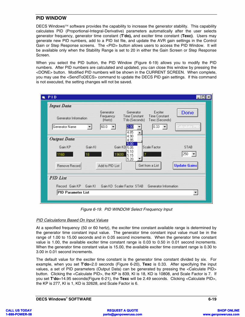
DECS Windows® SOFTWARE 6-19
PID WINDOW
DECS Windows software provides the capability to increase the generator stability. This capabilitycalculates PID (Proportional-Integral-Derivative) parameters automatically after the user selectsgenerator frequency, generator time constant (T'do), and exciter time constant (Texc). Users maygenerate new PID numbers, add to a PID list file, and update the AVR gain settings in the ControlGain or Step Response screens. The <PID> button allows users to access the PID Window. It willbe available only when the Stability Range is set to 20 in either the Gain Screen or Step ResponseScreen.
When you select the PID button, the PID Window (Figure 6-19) allows you to modify the PIDnumbers. After PID numbers are calculated and updated, you can close this window by pressing the<DONE> button. Modified PID numbers will be shown in the CURRENT SCREEN. When complete,you may use the <SendToDECS> command to update the DECS PID gain settings. If this commandis not executed, the setting changes will not be saved.
Figure 6-19. PID WINDOW Select Frequency Input
PID Calculations Based On Input Values
At a specified frequency (50 or 60 hertz), the exciter time constant available range is determined bythe generator time constant input value. The generator time constant input value must be in therange of 1.00 to 15.00 seconds and in 0.05 second increments. When the generator time constantvalue is 1.00, the available exciter time constant range is 0.03 to 0.50 in 0.01 second increments.When the generator time constant value is 15.00, the available exciter time constant range is 0.30 to3.00 in 0.01 second increments.
The default value for the exciter time constant is the generator time constant divided by six. Forexample, when you set T'do=2.0 seconds (Figure 6-20), Texc is 0.33. After specifying the inputvalues, a set of PID parameters (Output Data) can be generated by pressing the <Calculate PID>button. Clicking the <Calculate PID>, the KP is 839, KI is 18, KD is 10808, and Scale Factor is 7. Ifyou set T'do=14.95 seconds(Figure 6-21), the Texc will be 2.49 seconds. Clicking <Calculate PID>,the KP is 277, KI is 1, KD is 32628, and Scale Factor is 6.
CALL US TODAY 1-888-POWER-58
REQUEST A QUOTE [email protected]
SHOP ONLINE www.genpowerusa.com
CALL US TODAY 1-888-POWER-58
REQUEST A QUOTE [email protected]
SHOP ONLINE www.genpowerusa.com

6-20 DECS Windows® SOFTWARE
PID parameters can be directly added to, removed from, or modified in the PID List Data (Figure 6-22). PID parameters may also be saved to a file (pidlist.dat).
Retrieving Existing Data From PID List
Select one case from the PID List (Figure 6-22), then click the <Get from a List> button, therectangular black boxes will then show the PID numbers that were retrieved. <Update Gains> and<Done> buttons can be used to change the gain settings on the CURRENT SCREEN.
CAUTIONImproper PID numbers will result in poor system performance or equipment damage!
Figure 6-20. PID Window with a Texc Range when T'do is 2.00 Seconds
CALL US TODAY 1-888-POWER-58
REQUEST A QUOTE [email protected]
SHOP ONLINE www.genpowerusa.com
CALL US TODAY 1-888-POWER-58
REQUEST A QUOTE [email protected]
SHOP ONLINE www.genpowerusa.com

DECS Windows® SOFTWARE 6-21
Figure 6-21. PID WINDOW with a Texc Range when T'do is 14.95 Seconds
Figure 6-22. PID List Data
CALL US TODAY 1-888-POWER-58
REQUEST A QUOTE [email protected]
SHOP ONLINE www.genpowerusa.com
CALL US TODAY 1-888-POWER-58
REQUEST A QUOTE [email protected]
SHOP ONLINE www.genpowerusa.com

6-22 DECS Windows® SOFTWARE
TERMINATING COMMUNICATIONS
To terminate DECS communications, pull down the Communications menu and select Close(Figure 6-23). You are asked if you want to save the settings to EEPROM. This question is askedeven if you made no changes. When you execute the Close command (with a Yes or No to save thesettings to EEPROM), the communications is terminated. Pull down the File menu (Figure 6-24),choose Exit, and the DECS Windows software is terminated. If you choose to Exit the softwareprogram directly and not close the communications first, you will still be asked if you want to save thesettings to EEPROM.
Figure 6-23. Close Communications
Figure 6-24. Exit Windows® Software
CALL US TODAY 1-888-POWER-58
REQUEST A QUOTE [email protected]
SHOP ONLINE www.genpowerusa.com
CALL US TODAY 1-888-POWER-58
REQUEST A QUOTE [email protected]
SHOP ONLINE www.genpowerusa.com

CALL US1-888-POCALL US1-888-PO
MAINTENANCE 7-1
SECTION 7 • MAINTENANCE
PREVENTIVE MAINTENANCE
The only preventive maintenance required on the DECS is to periodically check the following:
• Be sure the connections between the DECS and the system are clean and tight.• Verify that the DECS cooling fins and housing are free from dust, dirt, and corrosion.
CORRECTIVE MAINTENANCE
The DECS has been designed for easy repair by replacement of electronic modules. Refer to Section8 for the replacement parts list.
WARRANTY AND REPAIR SERVICE
The Basler DECS is warranted against defective material and workmanship for 18 months from thedate of shipment from our factory. Units submitted for warranty repair should be returned to thefactory in Highland, Illinois, freight pre-paid, with a complete description of the installation and thereported problem. Pre-arrangement with either the nearest Basler Sales Office or with the CustomerService Department at the factory will assure the fastest possible turn-around time.
TROUBLESHOOTING
The more common generator system malfunctions and the appropriate repair procedures are in thefollowing paragraphs.
NO VOLTAGE BUILD-UP
Step 1. Verify that all wiring is properly connected. Refer to Figure 3-7 through 3-11.
If wiring is improperly connected, loose, miswired, etc., reconnect wiring properly.
If wiring is properly connected, proceed to Step 2.
Step 2. Check for correct power input to the DECS. Refer to Table 1-2, "Power Input"requirements.
If voltage is not present, refer to generator manual for PMG repair (PMG system only).
If voltage is present, proceed to Step 3.
Step 3. Verify that all fuses are not open.
If any fuse is open, replace fuse.
If all fuses are not open, proceed to Step 4.
Step 4. Verify that generator is up to rated speed.
If generator is not up to rated speed, increase generator speed to rated.
If generator is up to rated speed, proceed to Step 5.
TODAY WER-58
REQUEST A QUOTE [email protected]
SHOP ONLINE www.genpowerusa.com
TODAY WER-58
REQUEST A QUOTE [email protected]
SHOP ONLINE www.genpowerusa.com

7-2 MAINTENANCE
Step 5. If the DECS is being used in (non-PMG) mode, verify that the generator residual voltage isat least 8 Vac.
If the generator residual voltage is less than 8 Vac, refer to the generator manual and flashthe generator field.
If the generator residual voltage is 8 Vac or greater, proceed to Step 6.
Step 6. Verify that the front panel OVEREXC (Overexcitation) LED is extinguished.
If the front panel OVEREXC LED is illuminated, check the generator and/or loadconditions. Interrupt input power or shut down the generator for a minimum of 10seconds.
If the front panel OVEREXC LED is not illuminated, proceed to Step 7.
Step 7. Verify that the front panel OVERVOLT (Overvoltage) LED is extinguished.
If the front panel OVERVOLT LED is illuminated, check the generator and/or loadconditions. Interrupt input power or shut down the generator for a minimum of 10seconds.
If the front panel OVERVOLT LED is not illuminated, proceed to Step 8.
Step 8. Verify that the front panel OVERTEMP (Overtemperature) LED is extinguished.
If the front panel OVERTEMP LED is illuminated, increase cooling air to the DECS orallow the ambient air to cool. Interrupt input power or shut down the generator for aminimum of 10 seconds.
If the front panel OVERTEMP LED is not illuminated, proceed to Step 9.
Step 9. Replace the DECS unit.
If replacing the DECS unit does not correct the malfunction, then the generator isdefective. Consult with the generator manufacturer.
LOW OUTPUT VOLTAGE
Step 1. Verify that the Coarse Voltage adjustment is not set too low.
If the Coarse Voltage adjustment is too low, adjust it to a higher range.
If the Coarse Voltage adjustment is not too low, proceed to Step 2.
Step 2. Verify that the Fine Voltage adjustment is not set too low.
If the Fine Voltage adjustment is too low, adjust it to a higher range.
If the Fine Voltage adjustment is not too low, proceed to Step 3.
Step 3. Replace the DECS unit.
CALL US TODAY 1-888-POWER-58
REQUEST A QUOTE [email protected]
SHOP ONLINE www.genpowerusa.com
CALL US TODAY 1-888-POWER-58
REQUEST A QUOTE [email protected]
SHOP ONLINE www.genpowerusa.com

MAINTENANCE 7-3
HIGH OUTPUT VOLTAGE
Step 1. Verify that the Coarse Voltage adjustment is not set too high.
If the Coarse Voltage adjustment is too high, adjust it to a lower range.
If the Coarse Voltage adjustment is not too high, proceed to Step 2.
Step 2. Verify that the Fine Voltage adjustment is not set too high.
If the Fine Voltage adjustment is too high, adjust it to a lower range.
If the Fine Voltage adjustment is not too high, proceed to Step 3.
Step 3. Replace the DECS unit.
GENERATOR DOES NOT RESPOND AS ADJUSTMENTS ARE MADE
Step 1. Reset the DECS by interrupting input power or by shutting down the generator for aminimum of 10 seconds. If the generator still does not respond, proceed to Step 2.
Step 2. Replace the DECS unit.
POOR VOLTAGE REGULATION
Step 1. Verify that the case of the DECS is properly grounded.
If the DECS' case is not properly grounded, ground the DECS case by:
a) Connect dedicated ground wire to 1/4" faston labeled "GND" at rear of case.
If the DECS' case is properly grounded, proceed to Step 2.
Step 2. Check for grounded field leads.
If the field leads are grounded, isolate them from ground.
If the field leads are not grounded, proceed to Step 3.
Step 3. If used with a PMG, check for grounded PMG leads. If the PMG leads are grounded,isolate them from ground. If the PMG leads are not grounded, proceed to Step 4.
Step 4. Replace the DECS unit.
GENERATOR OUTPUT UNSTABLE (HUNTING)
Step 1. Verify that the genset prime mover governor is operating properly.
Step 2. Verify that the sensing and input power leads are connected securely.
If the sensing or input power leads are not connected securely, tighten the connections.
If the sensing or input power leads are connected securely, proceed to Step 3.
CALL US TODAY 1-888-POWER-58
REQUEST A QUOTE [email protected]
SHOP ONLINE www.genpowerusa.com
CALL US TODAY 1-888-POWER-58
REQUEST A QUOTE [email protected]
SHOP ONLINE www.genpowerusa.com

7-4 MAINTENANCE
Step 3. Verify that the Stability Range is set to the proper range. (Refer to Section 4.)
If the Stability Range is not set to the proper range, reset the Stability Range.
If the Stability Range is set to the proper range, proceed to Step 4.
Step 4. Verify that the Stability Level is properly set. (Refer to Section 4.)
If the Stability Level is not properly set, reselect the Stability Level.
FRONT PANEL UF (Underfrequency) LED IS ILLUMINATED
Step 1. Verify that the generator is operating at rated speed.
If the generator is not operating at rated speed, change the speed to the rated speed.
If the generator is operating at the rated speed, proceed to Step 2.
Step 2. Verify that the front panel Underfrequency setting is correct.
If the front panel Underfrequency setting is incorrect, reset the transition point.
Step 3. Verify that all sensing and power input connections are secure.
If connections are not secure, secure connections.
FRONT PANEL OVEREXC (Overexcitation) LED IS ILLUMINATED
Step 1. Check for generator overloading.
If generator is operating with a larger than rated load, shed load.
If generator is operating with a rated or less than rated load, proceed to Step 2.
Step 2. Replace the DECS unit. If replacing the DECS unit does not correct the malfunction,proceed to Step 3.
Step 3. Refer to generator manual. Generator is defective.
NO DROOP OR NEGATIVE DROOP (GENERATOR NOT SHARE LOAD)
Step 1. Check for open in Droop CT wiring.
If wiring is open, repair wiring as necessary.
If wiring is not open, proceed to Step 2.
Step 2. Verify that Droop CT polarity is correct.
If polarity is incorrect, reverse connections at terminals CTB1 and CTB2.
If polarity is not reversed, proceed to Step 3.
CALL US TODAY 1-888-POWER-58
REQUEST A QUOTE [email protected]
SHOP ONLINE www.genpowerusa.com
CALL US TODAY 1-888-POWER-58
REQUEST A QUOTE [email protected]
SHOP ONLINE www.genpowerusa.com

MAINTENANCE 7-5
Step 3. If the above steps fail to correct the malfunction, replace the DECS unit.
NO VOLTAGE MATCHING
Step 1. Verify Voltage Matching option was purchased and is enabled.
If not enabled, adjust state through front panel switches.
If enabled, proceed to Step 2.
Step 2. Verify all connections are correct per Figures 3-10 through 3-13 as required for theVoltage Matching optioned DECS.
If the interconnection is incorrect, reconnect per appropriate interconnect diagram.
If the interconnection is correct, proceed to Step 3.
Step 3. Check for correct utility reference voltage on DECS terminals BUS1 and BUS3.
If the interconnection is incorrect, reconnect per appropriate interconnect diagram.
If the interconnection is correct, check for open system fuses.
Verify correct sensing potential transformer, if used, is used on BUS1 and BUS3 leads.
If correct, proceed to Step 4.
Step 4. Verify the generator output voltage setpoint is within 20% of measured utility bus voltage.
If setpoint is too low, adjust Coarse Voltage (CV) to the appropriate level.
If setpoint is correct, proceed to Step 5.
Step 5. If the above steps fail to correct the Voltage Matching malfunction, replace the DECS.
FINE VOLTAGE ADJUST BAND NOT CENTERED AROUND THE COARSE VOLTAGE ADJUSTSETTING
Step 1 Use the SELECT button on the front panel to select coarse voltage adjust.
Step 2 Press and release the DECREASE button.
Step 3 Press and release the INCREASE button.
Step 4 Press and release the SELECT button.
OR , ALTERNATIVELY, USE THE DCIM:
Step 1 Select “Generator Voltage”
Step 2 Press and release <ENTER>.
CALL US TODAY 1-888-POWER-58
REQUEST A QUOTE [email protected]
SHOP ONLINE www.genpowerusa.com
CALL US TODAY 1-888-POWER-58
REQUEST A QUOTE [email protected]
SHOP ONLINE www.genpowerusa.com

7-6 MAINTENANCE
NO COMMUNICATION WITH DCIM UNIT
Step 1. Verify that the 9V battery is properly connected in the DCIM unit.
Remove the four screws on the front panel of the DCIM unit.
If battery is improperly connected, reconnect the battery.
If battery is properly connected, proceed to Step 2.
Step 2. Replace the 9V battery. If replacing the battery does not correct the malfunction,proceed to Step 3.
Step 3. Replace the DCIM unit.
CALL US TODAY 1-888-POWER-58
REQUEST A QUOTE [email protected]
SHOP ONLINE www.genpowerusa.com
CALL US TODAY 1-888-POWER-58
REQUEST A QUOTE [email protected]
SHOP ONLINE www.genpowerusa.com

CALL US TODAY 1-888-POWER-58CALL US TODAY 1-888-POWER-58
REPLACEMENT PARTS 8-1
SECTION 8 •••• REPLACEMENT PARTS
GENERAL
The following list (Table 8-1) describes the components and assemblies of the DECS that havemaintenance significance. When ordering parts from Basler Electric Company, be sure to specify theDECS Model and Style Number, reference Basler replacement part number, quantity, and description.
Table 8-1. Replacement Parts
Reference Part Number Qty. Description
-- 9 2849 00 101 1 DECS Power Module
-- 9 2653 00 025 1 Settings Label, adhesive-backed.
REQUEST A QUOTE [email protected]
SHOP ONLINE www.genpowerusa.com
REQUEST A QUOTE [email protected]
SHOP ONLINE www.genpowerusa.com

CALL US TOD1-888-POWER-
E m
CALL US TOD1-888-POWER-
E m
MANUAL CHANGE INFORMATION 9-1
SECTION 9 •••• MANUAL CHANGE INFORMATION
CHANGESSubstantive changes in this manual to date are summarized in Table 9-1.
Table 9-1. Summary of Changes
Revision Summary of ChangesECA/ECO
No. DateA Revised the manual to reflect the change in the software name from
“DCOM” to “BESTCOMS-DECS15-32/16.”16430 11/97
B Corrected pages 1-2, 1-3, and 2-2 where “W” should be “ohms.”Updated Figure 3-6. Corrected Figure 3-7 in Note 3 from “+ OR - 1VDC” to “+ OR - 3 VDC.” Section 4 added note to Table 4-4 “Forversions 2.0.0 or later, it is recommended that Droop Mode be activewhen VAR/PF is active.” Changed all occurrences of “start up” to “start-up” in Section 5. Page 5-4 corrected DECS ADJUSTMENT WINDOW,from “Step_resp” to “STEP_RESP”. Page 5-5 corrected “Step_resp/ALT-R” to “STEP_RESP/ALT-S”. Page 5-8 changed UEL Settingparagraph , third sentence from “CAR” to “CTR”. Also changed the lastparagraph, first sentence from “a faster start up speed, lower start-uptime,” to “a faster start-up speed (less start-up time)”. Page 5-11,changed the Help Window to explain the commands more thoroughly.Section 6, changed all “VAr” to “VAR”.
16657 03/98
C To incorporate changes initiated by ECA 16757 involving the DCIM.Revised page 4-1 to remove reference to p/n 9 2745 00 101 and page 4-14 to add the three available part numbers for operating software for theDCIM. Also added the functions that are adjustable by the DCIM.Updated Figure 5-1 to reflect the new part number “9 2745 03 100.”
16795 06/98
D Changed page 1-1, added the digit 1 to the style number example.Added new Figure 3-7 and bumped up old Figures 3-7 through 3-11.Corrected UEL range on pages 5-8 and 6-8, from 0 - 100% to 0 - 80%.Corrected the Fine voltage Adjust speed (FVAS) description on pages 5-6 and 6-8.
2272 02/99
E Correct figure reference to Figure 3-12 on page 4-9. Added a Caution toSection 3, Power Output. F+ and F- terminals should never be shortedtogether.
7727 01/2000
AY 58
REQUEST A QUOTE [email protected]
SHOP ONLINwww.genpowerusa.co
AY 58
REQUEST A QUOTE [email protected]
SHOP ONLINwww.genpowerusa.co