Embed Size (px)
Citation preview
DECS-300 Digital Excitation Control System
SZE-3 8-00
• Microprocessor-based design
• True RMS sensing, single or three phase
• Controls the firing of external bridges by outputting 4-20mA, 0-10Vdc or ±10Vdc
• 0.25% Voltage Regulation Accuracy
• Setup from front panel HMI or by PC with free Windows® setup software
• 40 standard stability selections
• User customizable stability selection
• Paralleling compensation
• 0 to 3 times Volts per Hertz Underfrequency compensation
• Softstart buildup
• Field Current Regulation Mode (Manual Mode)
• Autotracking between operating modes and between DECS-300 units
• Autotransfer to a back-up DECS-300 unit
• Remote setpoint control via:- Contact inputs- Proportional control via ±3Vdc, 0-10Vdc, or 4-20mA- Communications inputs RS-232 (ASCII) or RS-485 (Modbus™)
• Minimum Excitation Limiter
• On and off-line Maximum Excitation Limiters
• VAR and Power Factor Controllers (continued on next page)
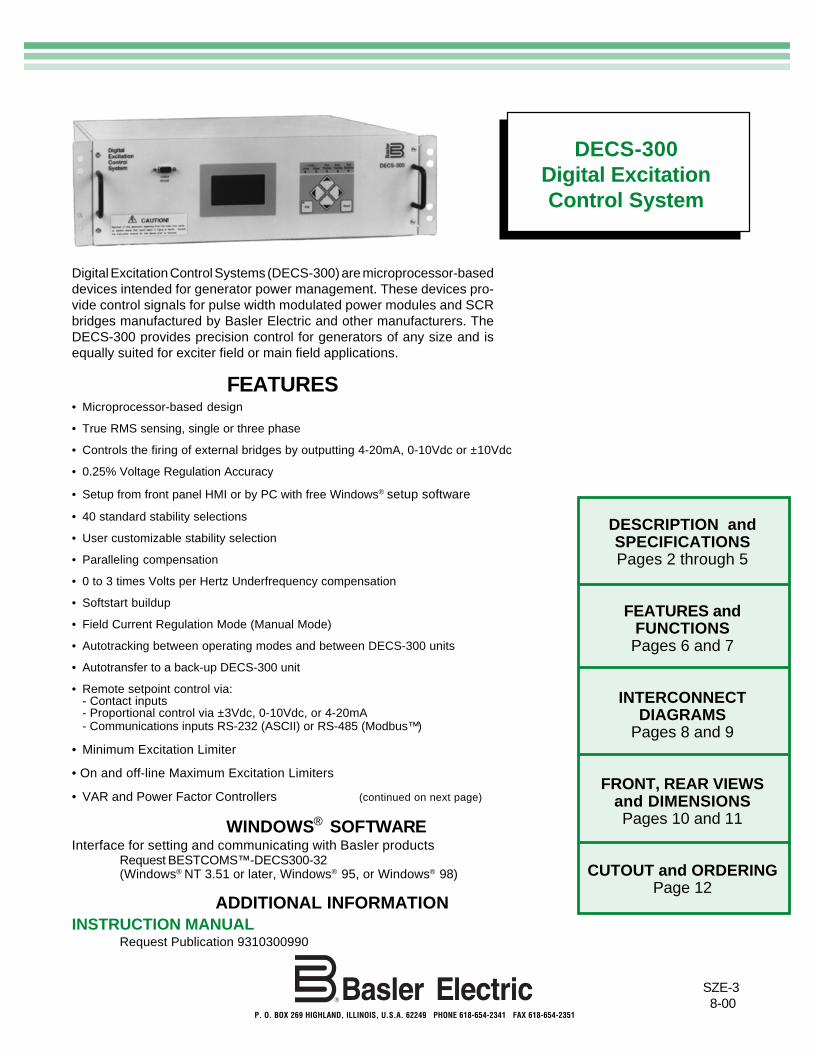
Digital Excitation Control Systems (DECS-300) are microprocessor-baseddevices intended for generator power management. These devices pro-vide control signals for pulse width modulated power modules and SCRbridges manufactured by Basler Electric and other manufacturers. TheDECS-300 provides precision control for generators of any size and isequally suited for exciter field or main field applications.
DECS-300Digital ExcitationControl System
P. O. BOX 269 HIGHLAND, ILLINOIS, U.S.A. 62249 PHONE 618-654-2341 FAX 618-654-2351
DESCRIPTION andSPECIFICATIONSPages 2 through 5
FEATURES andFUNCTIONSPages 6 and 7
INTERCONNECTDIAGRAMS
Pages 8 and 9
FRONT, REAR VIEWSand DIMENSIONSPages 10 and 11
CUTOUT and ORDERINGPage 12
FEATURES
ADDITIONAL INFORMATIONINSTRUCTION MANUAL
Request Publication 9310300990
WINDOWS® SOFTWAREInterface for setting and communicating with Basler products
Request BESTCOMS™-DECS300-32(Windows® NT 3.51 or later, Windows® 95, or Windows® 98)
DECS-300 Digital Excitation Control System
2
FEATURES, continued
DESCRIPTION
INPUTS
Power InputDECS-300-L: 24/48Vdc nominal (16-60Vdc), Burden=30W.
DECS-300-C: 120Vac nominal (85 to 132Vac, 50 or 60Hz), Burden=5VA.125Vdc nominal (90 to 150Vdc), Burden=30W.
Generator Voltage Sensing Single-phase or three-phase line voltage, two ranges:• 100V/50Hz nominal (85 to 127V), 120V/60Hz nominal (94 to 153V)• 200V/50Hz nominal (170 to 254V), 240V/60Hz nominal (187 to 305V)
Bus Voltage Sensing Single-phase line voltage (AC), two ranges:• 100V/50Hz nominal (85 to 127V), 120V/60Hz nominal (94 to 153V)• 200V/50Hz nominal (170 to 254V), 240V/60Hz nominal (187 to 305V)
Generator Current Sensing Two ac current sensing ranges and two channel (phase) inputs• 1A, phase B; 1A, phases A or C• 5A, phase B; 5A, phases A or C
SPECIFICATIONS
The DECS-300 is a microprocessor based excitationcontroller. It provides output control signals to controlthe firing (output) of an external power bridge. TheDECS-300 is designed to work with Basler Electric'sSSE and SSEN power bridges, but will work equallywell with any power bridge suitable for use on asynchronous generator/motor that has a firing circuitcapable of accepting the control signal output from theDECS-300. The DECS-300 is a total excitation controlsystem in one 19 inch rack mount enclosure. It con-tains all the functionality necessary to limit, control andprotect a generator from operating outside of themachine's capability. DECS-300's sophisticated design
allows the nonactive control mode, within the unit, tofollow the active mode, permitting bumpless transferbetween modes. The software also allows for unit-to-unit communication, permitting autofollowing andtransfer between DECS-300 units. It can also commu-nicate to a PC via the front panel RS-232 port for localprogramming and metering, and it can communicatevia Modbus™ protocol via the rear-mounted RS-485port for communications up to 4000 feet away from theDECS-300 unit. The DECS-300 has all the features,functionality, flexibility and programmability expectedfrom a state-of-the-art microprocessor based product.
• Voltage Matching
• 4 generator protection features
• Programmable output contacts
• Front panel backlit LCD display
• Front panel mounted RS-232 and rear-mountedRS-485 communications ports
• Modbus™ protocol for RS-485 input allowscommunications up to 4000 feet away
• <1% metering accuracy for 12 generator parameters
• Meets C37.90.1-1989 for Surge Withstand and FastTransient
• UL Recognized and CSA Certified
• U.S. Patent Number 5,294,879
APPLICATIONSThe DECS-300 is an excitation control system used to control the output voltage, VARs or Power Factor of asynchronous generator by varying or controlling the amount of dc excitation applied to either the generator's mainfield or exciter field. The DECS-300 is suitable for virtually any kW size machine.
DECS-300 Digital Excitation Control System
3
SPECIFICATIONS, continued
Sensing Burden Voltage: Less than 1VA per phase.Current: Less than 1VA.Parallel Compensation: Less than 1VA.
Contact Switching Inputs Thirteen contact switching inputs are supplied with 24Vdc to accommodate drycontacts. Contacts are as follows:• Start • VAR/PF Enable• Stop • Pre-position• Autotransfer Enabled • Raise Switch• Unit/Parallel Operation • Lower Switch• Autotrack Enable • General Purpose Switch #1• AVR Mode • General Purpose Switch #2• FCR Mode
Remote Setpoint Control Two separate analog inputs for remote setpoint control (select one from the(Accessory Input) configuration menu)
• ±10Vdc• 4 to 20 milliamperes
OUTPUTS
Control Outputs Two analog outputs for setpoint control (select one from the configuration menu)• ±10Vdc or 0 to +10Vdc• 4 to 20 milliamperes
Contact OutputsMake and carry for 30 amperes for 0.2 seconds per ANSI C37.90; continuous for 7 amperestripping duty
Break resistive or 0.3 amperes at 125 or 250Vdc (L/R=0.04 maximum).inductive
Eight output contacts rated as described with 300 volt surge suppressors in-stalled across contacts to prevent arcing from inductive loads. Contacts are asfollows:• Buildup • Relay #4• Fail-to-flash • Relay #3• Watchdog • Relay #2• Start/Stop • Relay #1
ISOLATION MODULE Operating voltage + and - 12Vdc from DECS-300.(Isolation module and case Five field voltage sensing ranges: 32, 63, 125, 250 and 375 voltsare included with DECS-300) Field analog output signal: 0.9 to 9.1Vdc(5.0Vdc=0 field voltage)
Two field current sensing ranges: 50 and 100 millivolts.Field analog output signal: 2.0 to 9.5Vdc (2.0Vdc=0 field current)
COMMUNICATION There are three communication ports, two RS-232 and one RS-485.COM0: RS-232, 9 pin, sub-D connector located on front panel and used to
communicate with local computers. 1200 to 19200 baud, 8N1 fullduplex, ASCII commands
COM1: RS-232, 9 pin, sub-D connector located on rear panel and used toconnect primary and backup DECS-300 units or other devices. 1200 to19200 baud, 8N1 full duplex, unique ASCII commands, only used forautotracking
DECS-300 Digital Excitation Control System
4
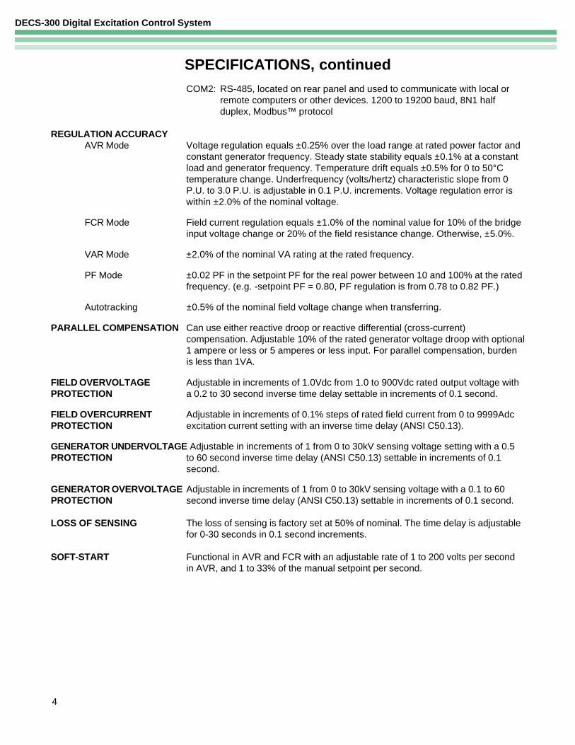
SPECIFICATIONS, continuedCOM2: RS-485, located on rear panel and used to communicate with local or
remote computers or other devices. 1200 to 19200 baud, 8N1 halfduplex, Modbus™ protocol
REGULATION ACCURACYAVR Mode Voltage regulation equals ±0.25% over the load range at rated power factor and
constant generator frequency. Steady state stability equals ±0.1% at a constantload and generator frequency. Temperature drift equals ±0.5% for 0 to 50°Ctemperature change. Underfrequency (volts/hertz) characteristic slope from 0P.U. to 3.0 P.U. is adjustable in 0.1 P.U. increments. Voltage regulation error iswithin ±2.0% of the nominal voltage.
FCR Mode Field current regulation equals ±1.0% of the nominal value for 10% of the bridgeinput voltage change or 20% of the field resistance change. Otherwise, ±5.0%.
VAR Mode ±2.0% of the nominal VA rating at the rated frequency.
PF Mode ±0.02 PF in the setpoint PF for the real power between 10 and 100% at the ratedfrequency. (e.g. -setpoint PF = 0.80, PF regulation is from 0.78 to 0.82 PF.)
Autotracking ±0.5% of the nominal field voltage change when transferring.
PARALLEL COMPENSATION Can use either reactive droop or reactive differential (cross-current)compensation. Adjustable 10% of the rated generator voltage droop with optional1 ampere or less or 5 amperes or less input. For parallel compensation, burdenis less than 1VA.
FIELD OVERVOLTAGE Adjustable in increments of 1.0Vdc from 1.0 to 900Vdc rated output voltage withPROTECTION a 0.2 to 30 second inverse time delay settable in increments of 0.1 second.
FIELD OVERCURRENT Adjustable in increments of 0.1% steps of rated field current from 0 to 9999AdcPROTECTION excitation current setting with an inverse time delay (ANSI C50.13).
GENERATOR UNDERVOLTAGE Adjustable in increments of 1 from 0 to 30kV sensing voltage setting with a 0.5PROTECTION to 60 second inverse time delay (ANSI C50.13) settable in increments of 0.1
second.
GENERATOR OVERVOLTAGE Adjustable in increments of 1 from 0 to 30kV sensing voltage with a 0.1 to 60PROTECTION second inverse time delay (ANSI C50.13) settable in increments of 0.1 second.
LOSS OF SENSING The loss of sensing is factory set at 50% of nominal. The time delay is adjustablefor 0-30 seconds in 0.1 second increments.
SOFT-START Functional in AVR and FCR with an adjustable rate of 1 to 200 volts per secondin AVR, and 1 to 33% of the manual setpoint per second.
DECS-300 Digital Excitation Control System
5
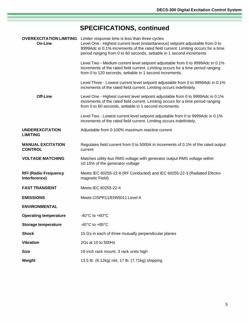
OVEREXCITATION LIMITING Limiter response time is less than three cycles.On-Line Level One - Highest current level (instantaneous) setpoint adjustable from 0 to
9999Adc in 0.1% increments of the rated field current. Limiting occurs for a timeperiod ranging from 0 to 60 seconds, settable in 1 second increments
Level Two - Medium current level setpoint adjustable from 0 to 9999Adc in 0.1%increments of the rated field current. Limiting occurs for a time period rangingfrom 0 to 120 seconds, settable in 1 second increments.
Level Three - Lowest current level setpoint adjustable from 0 to 9999Adc in 0.1%increments of the rated field current. Limiting occurs indefinitely.
Off-Line Level One - Highest current level setpoint adjustable from 0 to 9999Adc in 0.1%increments of the rated field current. Limiting occurs for a time period rangingfrom 0 to 60 seconds, settable in 1 second increments.
Level Two - Lowest current level setpoint adjustable from 0 to 9999Adc in 0.1%increments of the rated field current. Limiting occurs indefinitely.
UNDEREXCITATION Adjustable from 0-100% maximum reactive currentLIMITING
MANUAL EXCITATION Regulates field current from 0 to 5000A in increments of 0.1% of the rated outputCONTROL current
VOLTAGE MATCHING Matches utility bus RMS voltage with generator output RMS voltage within±0.15% of the generator voltage
RFI (Radio Frequency Meets IEC 60255-22-6 (RF Conducted) and IEC 60255-22-3 (Radiated Electro-Interference) magnetic Field)
FAST TRANSIENT Meets IEC 60255-22-4
EMISSIONS Meets CISPR11/EN55011 Level A
ENVIRONMENTAL
Operating temperature -40°C to +60°C
Storage temperature -40°C to +85°C
Shock 15 Gs in each of three mutually perpendicular planes
Vibration 2Gs at 10 to 500Hz
Size 19 inch rack mount, 3 rack units high
Weight 13.5 lb. (6.12kg) net, 17 lb. (7.71kg) shipping
SPECIFICATIONS, continued
DECS-300 Digital Excitation Control System
6
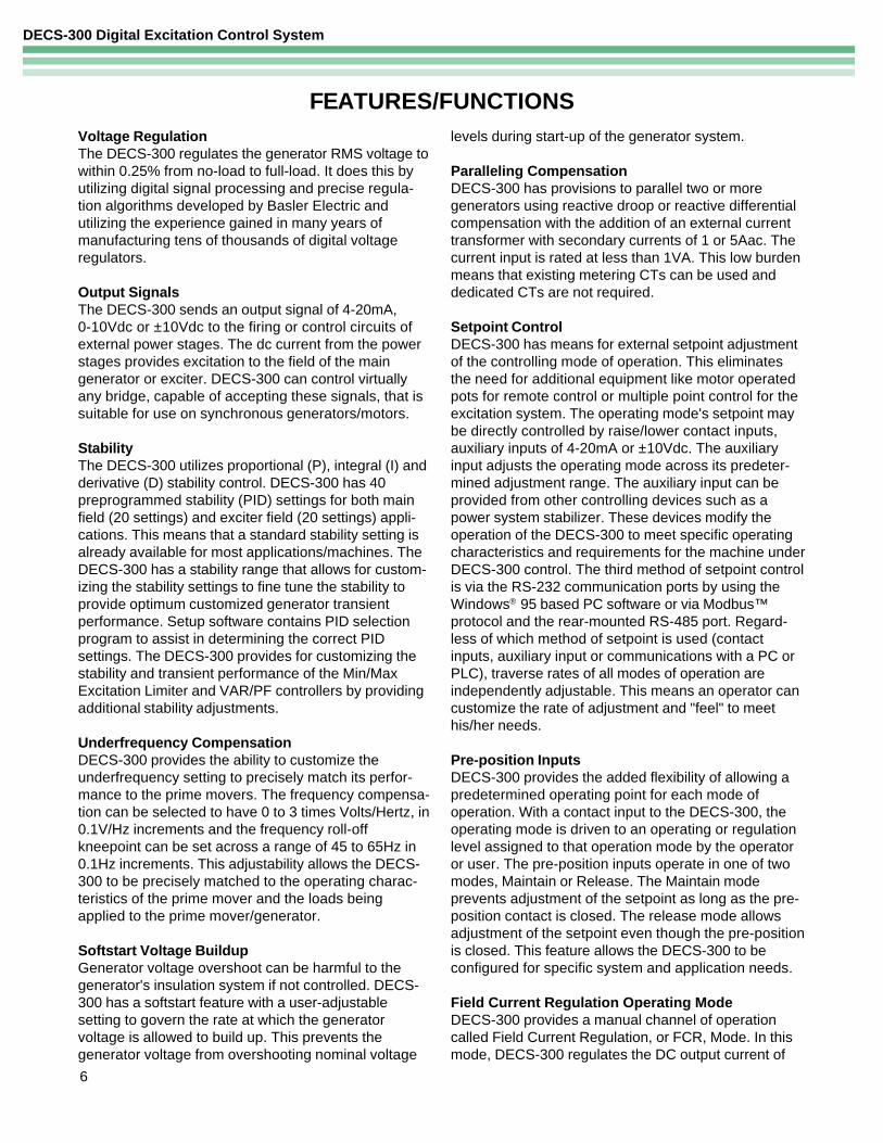
FEATURES/FUNCTIONSVoltage RegulationThe DECS-300 regulates the generator RMS voltage towithin 0.25% from no-load to full-load. It does this byutilizing digital signal processing and precise regula-tion algorithms developed by Basler Electric andutilizing the experience gained in many years ofmanufacturing tens of thousands of digital voltageregulators.
Output SignalsThe DECS-300 sends an output signal of 4-20mA,0-10Vdc or ±10Vdc to the firing or control circuits ofexternal power stages. The dc current from the powerstages provides excitation to the field of the maingenerator or exciter. DECS-300 can control virtuallyany bridge, capable of accepting these signals, that issuitable for use on synchronous generators/motors.
StabilityThe DECS-300 utilizes proportional (P), integral (I) andderivative (D) stability control. DECS-300 has 40preprogrammed stability (PID) settings for both mainfield (20 settings) and exciter field (20 settings) appli-cations. This means that a standard stability setting isalready available for most applications/machines. TheDECS-300 has a stability range that allows for custom-izing the stability settings to fine tune the stability toprovide optimum customized generator transientperformance. Setup software contains PID selectionprogram to assist in determining the correct PIDsettings. The DECS-300 provides for customizing thestability and transient performance of the Min/MaxExcitation Limiter and VAR/PF controllers by providingadditional stability adjustments.
Underfrequency CompensationDECS-300 provides the ability to customize theunderfrequency setting to precisely match its perfor-mance to the prime movers. The frequency compensa-tion can be selected to have 0 to 3 times Volts/Hertz, in0.1V/Hz increments and the frequency roll-offkneepoint can be set across a range of 45 to 65Hz in0.1Hz increments. This adjustability allows the DECS-300 to be precisely matched to the operating charac-teristics of the prime mover and the loads beingapplied to the prime mover/generator.
Softstart Voltage BuildupGenerator voltage overshoot can be harmful to thegenerator's insulation system if not controlled. DECS-300 has a softstart feature with a user-adjustablesetting to govern the rate at which the generatorvoltage is allowed to build up. This prevents thegenerator voltage from overshooting nominal voltage
levels during start-up of the generator system.
Paralleling CompensationDECS-300 has provisions to parallel two or moregenerators using reactive droop or reactive differentialcompensation with the addition of an external currenttransformer with secondary currents of 1 or 5Aac. Thecurrent input is rated at less than 1VA. This low burdenmeans that existing metering CTs can be used anddedicated CTs are not required.
Setpoint ControlDECS-300 has means for external setpoint adjustmentof the controlling mode of operation. This eliminatesthe need for additional equipment like motor operatedpots for remote control or multiple point control for theexcitation system. The operating mode's setpoint maybe directly controlled by raise/lower contact inputs,auxiliary inputs of 4-20mA or ±10Vdc. The auxiliaryinput adjusts the operating mode across its predeter-mined adjustment range. The auxiliary input can beprovided from other controlling devices such as apower system stabilizer. These devices modify theoperation of the DECS-300 to meet specific operatingcharacteristics and requirements for the machine underDECS-300 control. The third method of setpoint controlis via the RS-232 communication ports by using theWindows® 95 based PC software or via Modbus™protocol and the rear-mounted RS-485 port. Regard-less of which method of setpoint is used (contactinputs, auxiliary input or communications with a PC orPLC), traverse rates of all modes of operation areindependently adjustable. This means an operator cancustomize the rate of adjustment and "feel" to meethis/her needs.
Pre-position InputsDECS-300 provides the added flexibility of allowing apredetermined operating point for each mode ofoperation. With a contact input to the DECS-300, theoperating mode is driven to an operating or regulationlevel assigned to that operation mode by the operatoror user. The pre-position inputs operate in one of twomodes, Maintain or Release. The Maintain modeprevents adjustment of the setpoint as long as the pre-position contact is closed. The release mode allowsadjustment of the setpoint even though the pre-positionis closed. This feature allows the DECS-300 to beconfigured for specific system and application needs.
Field Current Regulation Operating ModeDECS-300 provides a manual channel of operationcalled Field Current Regulation, or FCR, Mode. In thismode, DECS-300 regulates the DC output current of
DECS-300 Digital Excitation Control System
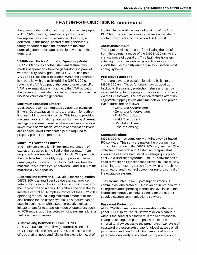
FEATURES/FUNCTIONS, continuedthe power bridge. It does not rely on the sensing inputto DECS-300 and is, therefore, a good source ofbackup excitation control when loss of sensing isdetected. In this mode, control of the generator istotally dependent upon the operator to maintainnominal generator voltage as the load varies on thegenerator.
VAR/Power Factor Controller Operating ModeDECS-300 has, as another standard feature, twomodes of operation when the generator is in parallelwith the utility power grid. The DECS-300 has bothVAR and PF modes of operation. When the generatoris in parallel with the utility grid, the DECS-300 canregulate the VAR output of the generator to a specificVAR level magnitude or it can vary the VAR output ofthe generator to maintain a specific power factor as thekW load varies on the generator.
Maximum Excitation LimitersEach DECS-300 has integrated over/underexcitationlimiters. Overexcitation limiters are present for both on-line and off-line excitation levels. This feature providesmaximum overexcitation protection by having differentsettings for off-line operation where load levels requirelower levels of excitation. When lower excitation levelsare needed, lower limiter settings are required toproperly protect the generator.
Minimum Excitation LimiterThe minimum excitation limiter limits the amount ofexcitation supplied to the field of the generator fromdropping below unsafe operating levels. This preventsthe machine from possibly slipping poles and fromdamaging the machine. It limits the VAR low from themachine to a preset level of between 0 and 100% of themachine's VAR capability.
Autotracking Between DECS-300 Operating ModesDECS-300 is an intelligent device that can provideautotracking (autofollowing) of the controlling mode bythe non-controlling modes. This allows the operator toinitiate a controlled, bumpless transfer of the DECS-300operating modes, causing minimum amounts of linedisturbance for the power system. This feature can beused in conjunction with a set of protective relays toinitiate a transfer to a backup mode of operation, suchas FCR mode, upon the detection of a system failure orfault, i.e., loss of sensing.
Autotracking Between DECS-300 UnitsA DECS-300 can also follow (autotrack) a secondDECS-300 unit. The first DECS-300 is put into a spe-cific operating mode and follows the excitation level of
the first. In the unlikely event of a failure of the firstDECS-300, protective relays can initiate a transfer ofcontrol from the first to the second DECS-300.
Autotransfer InputThis input provides a means for initiating the transferfrom the operating mode of the DECS-300 unit to themanual mode of operation. This facilitates transfersinitiating from some external protective relay andavoids the use of costly auxiliary relays used on mostanalog systems.
Protective FunctionsThere are several protection functions built into theDECS-300 unit. These functions may be used asbackup to the primary protection relays and can beassigned to up to four programmable output contactsvia the PC software. The protection features offer fullyadjustable tripping levels and time delays. The protec-tive features are as follows:
• Generator Overvoltage• Generator Undervoltage• Field Overvoltage• Field Overcurrent• Watchdog Timer• Loss of Sensing
CommunicationsDECS-300 comes complete with Windows® 95 basedPC software. This software makes the programmingand customization of the DECS-300 easy and fast. Thesoftware comes with a PID selection program thatallows the user to select stability settings quickly andeasily in a user-friendly format. The PC software has aspecial monitoring function that allows the user to viewall settings, a metering screen for viewing all machineparameters, and a control screen for remote control ofthe excitation system.
The rear-mounted RS-485 port supports Modbus™communications protocol. This is an open protocol withall registers and operating instructions available in theinstruction manual, to make it simple for the user todevelop custom communications software.
Password ProtectionAll DECS-300 parameters are viewable via the frontpanel LCD display, the PC software or via Modbus™without the need of a password. If the user wishes tochange a setting, the proper password must beentered to allow access to the parameter. Two levels ofpassword protection exist, one for global access of allparameters and one for a limited amount of access toparameters normally associated with operator control.
7
DECS-300 Digital Excitation Control System
8
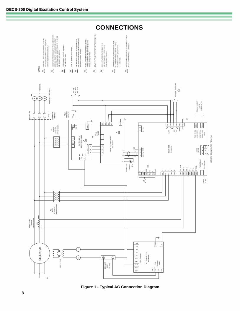
CONNECTIONS
Figure 1 - Typical AC Connection Diagram
DECS-300 Digital Excitation Control System
9
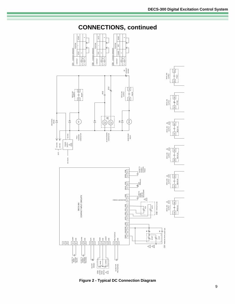
Figure 2 - Typical DC Connection Diagram
CONNECTIONS, continued
DECS-300 Digital Excitation Control System
10
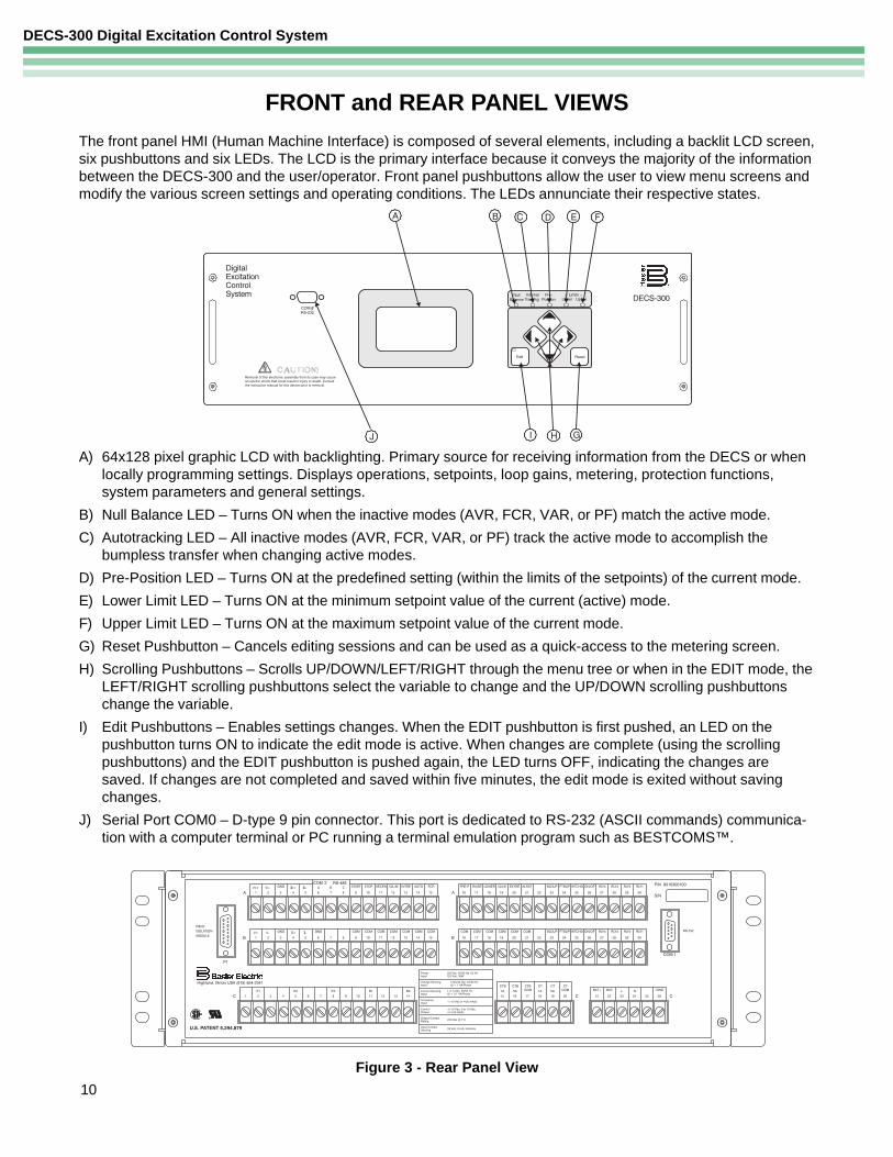
The front panel HMI (Human Machine Interface) is composed of several elements, including a backlit LCD screen,six pushbuttons and six LEDs. The LCD is the primary interface because it conveys the majority of the informationbetween the DECS-300 and the user/operator. Front panel pushbuttons allow the user to view menu screens andmodify the various screen settings and operating conditions. The LEDs annunciate their respective states.
A) 64x128 pixel graphic LCD with backlighting. Primary source for receiving information from the DECS or whenlocally programming settings. Displays operations, setpoints, loop gains, metering, protection functions,system parameters and general settings.
B) Null Balance LED – Turns ON when the inactive modes (AVR, FCR, VAR, or PF) match the active mode.
C) Autotracking LED – All inactive modes (AVR, FCR, VAR, or PF) track the active mode to accomplish thebumpless transfer when changing active modes.
D) Pre-Position LED – Turns ON at the predefined setting (within the limits of the setpoints) of the current mode.
E) Lower Limit LED – Turns ON at the minimum setpoint value of the current (active) mode.
F) Upper Limit LED – Turns ON at the maximum setpoint value of the current mode.
G) Reset Pushbutton – Cancels editing sessions and can be used as a quick-access to the metering screen.
H) Scrolling Pushbuttons – Scrolls UP/DOWN/LEFT/RIGHT through the menu tree or when in the EDIT mode, theLEFT/RIGHT scrolling pushbuttons select the variable to change and the UP/DOWN scrolling pushbuttonschange the variable.
I) Edit Pushbuttons – Enables settings changes. When the EDIT pushbutton is first pushed, an LED on thepushbutton turns ON to indicate the edit mode is active. When changes are complete (using the scrollingpushbuttons) and the EDIT pushbutton is pushed again, the LED turns OFF, indicating the changes aresaved. If changes are not completed and saved within five minutes, the edit mode is exited without savingchanges.
J) Serial Port COM0 – D-type 9 pin connector. This port is dedicated to RS-232 (ASCII commands) communica-tion with a computer terminal or PC running a terminal emulation program such as BESTCOMS™.
FRONT and REAR PANEL VIEWS
Figure 3 - Rear Panel View
DECS-300 Digital Excitation Control System
11
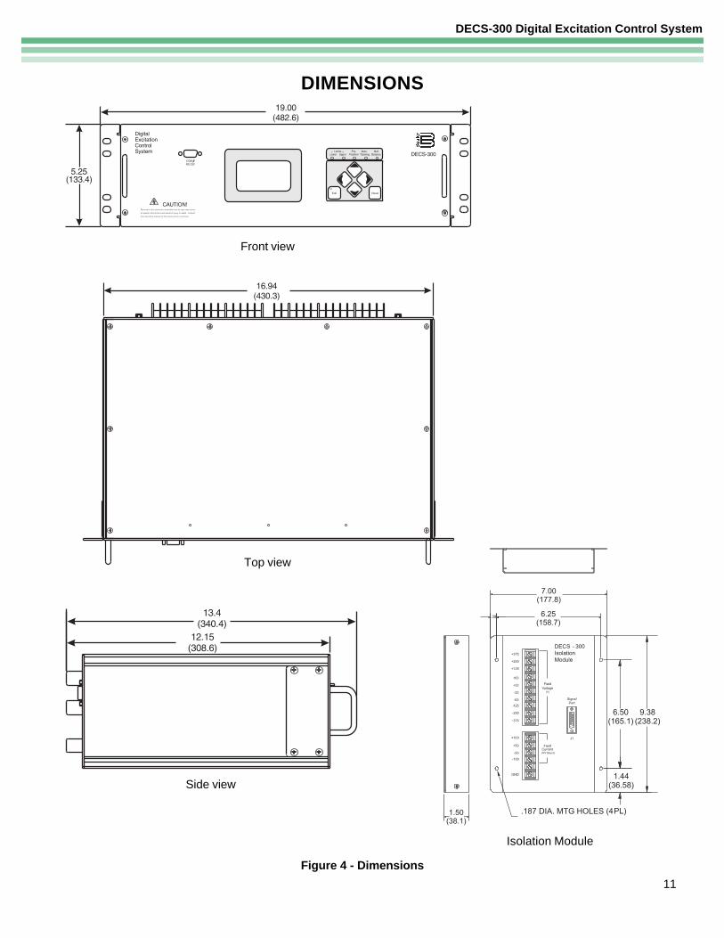
Figure 4 - Dimensions
DIMENSIONS
Side view
Front view
Top view
Isolation Module
DECS-300 Digital Excitation Control System
ROUTE 143, BOX 269, HIGHLAND, ILLINOIS U.S.A. 62249PHONE 618-654-2341 FAX 618-654-2351
P.A.E. Les Pins, 67319 Wasselonne Cedex FRANCEPHONE (33-3-88) 87-1010 FAX (33-3-88) 87-0808
http://www.basler.com, [email protected]
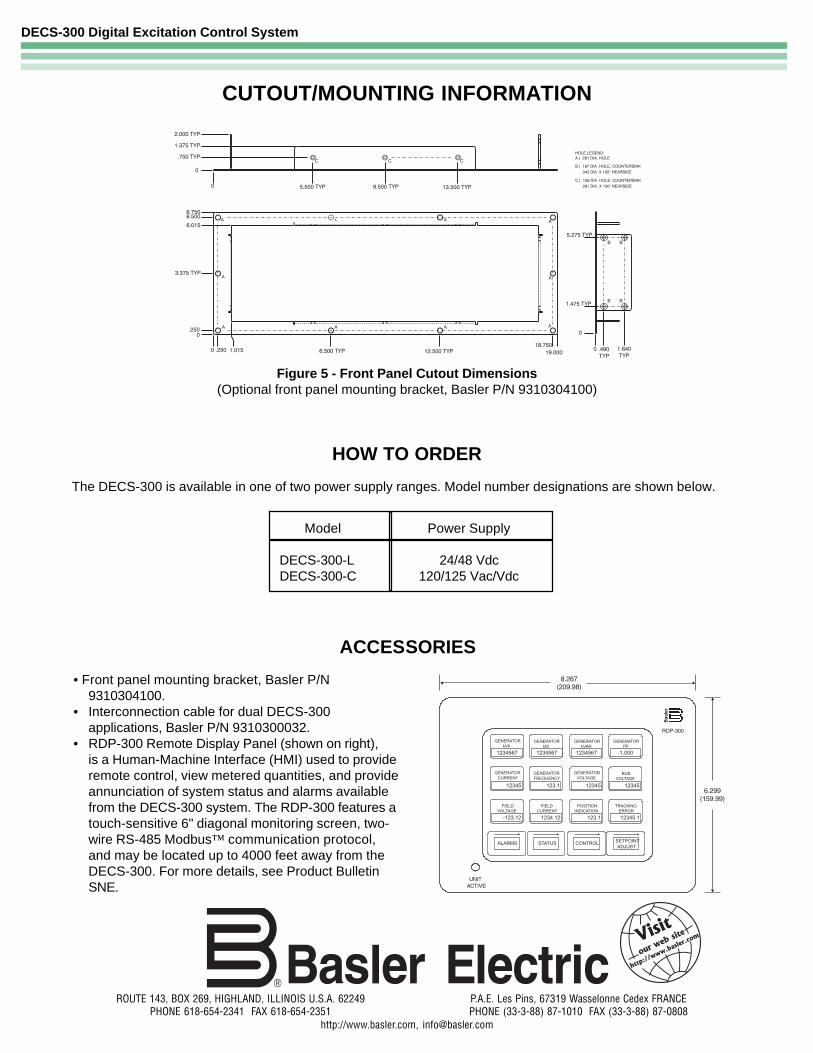
CUTOUT/MOUNTING INFORMATION
Figure 5 - Front Panel Cutout Dimensions(Optional front panel mounting bracket, Basler P/N 9310304100)
HOW TO ORDER
Model Power Supply
DECS-300-L 24/48 Vdc DECS-300-C 120/125 Vac/Vdc
ACCESSORIES
• Front panel mounting bracket, Basler P/N9310304100.
• Interconnection cable for dual DECS-300applications, Basler P/N 9310300032.
• RDP-300 Remote Display Panel (shown on right),is a Human-Machine Interface (HMI) used to provideremote control, view metered quantities, and provideannunciation of system status and alarms availablefrom the DECS-300 system. The RDP-300 features atouch-sensitive 6" diagonal monitoring screen, two-wire RS-485 Modbus™ communication protocol,and may be located up to 4000 feet away from theDECS-300. For more details, see Product BulletinSNE.
The DECS-300 is available in one of two power supply ranges. Model number designations are shown below.