Embed Size (px)
Citation preview
Decorating Surfaces withBidirectional Texture Functions
Kun Zhou, Peng Du, Lifeng Wang, Yasuyuki Matsushita, Member, IEEE,
Jiaoying Shi, Baining Guo, and Heung-Yeung Shum
Abstract—We present a system for decorating arbitrary surfaces with bidirectional texture functions (BTF). Our system generates
BTFs in two steps. First, we automatically synthesize a BTF over the target surface from a given BTF sample. Then, we let the user
interactively paint BTF patches onto the surface such that the painted patches seamlessly integrate with the background patterns. Our
system is based on a patch-based texture synthesis approach known as quilting. We present a graphcut algorithm for BTF synthesis
on surfaces and the algorithm works well for a wide variety of BTF samples, including those which present problems for existing
algorithms. We also describe a graphcut texture painting algorithm for creating new surface imperfections (e.g., dirt, cracks, scratches)
from existing imperfections found in input BTF samples. Using these algorithms, we can decorate surfaces with real-world textures that
have spatially-variant reflectance, fine-scale geometry details, and surfaces imperfections. A particularly attractive feature of
BTF painting is that it allows us to capture imperfections of real materials and paint them onto geometry models. We demonstrate the
effectiveness of our system with examples.
Index Terms—Bidirectional texture function, texture synthesis, interactive surface painting.
�
1 INTRODUCTION
TEXTURE mapping was introduced in [5] as a way to addsurface detail without adding geometry. Texture-
mapped polygons have since become the basic primitivesof the standard graphics pipeline. Unfortunately, texture-mapped surfaces do have a distinctive look that sets themapart from reality: They cannot accurately respond tochanges in illumination and viewpoint. Real-world surfacesoften are not smooth, but are covered with textures thatarise from both spatially-variant reflectance and fine-scalegeometry details known as mesostructures [16]. Real surfacesalso exhibit imperfections, e.g., dirt, cracks, and scratches,which usually result from rather complicated physicalprocesses. Capturing these surface characteristics is achallenging goal for computer graphics.
To bring us closer to that goal, we develop a system for
decorating arbitrary surfaces with BTFs [6]. Our system
supports two high-level texturing operations: tiling and
painting. Given a BTF sample, the tiling operation auto-
matically synthesizes a BTF that fits the target surface
naturally and seamlessly. The BTF can model spatially-
variant reflectance and mesostructures. Moreover, the BTF
can be measured from real materials. Thus, the tiling
operation provides a convenient way to cover a surface
with fairly realistic textures.
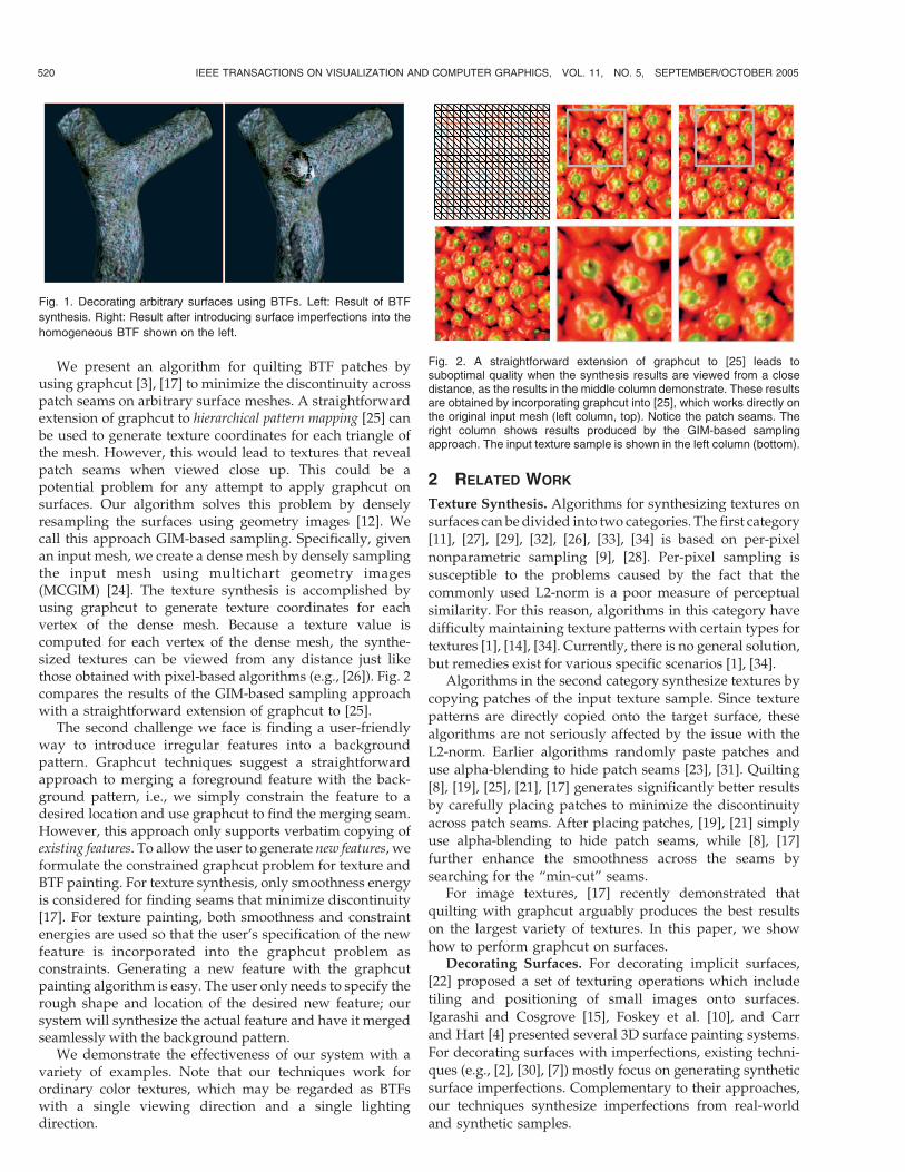
The painting operation further enhances realism byintroducing imperfections and other irregular features, asshown in Fig. 1 and Fig. 7. This operation is valuablebecause BTFs generated by our synthesis algorithm, as wellas by most other synthesis algorithms, are homogeneousacross the whole surface. With the painting operation, wecan break this global homogeneity by adding irregular localfeatures. In particular, we can capture imperfections of realmaterials and paint them onto the surface such that thepainted imperfections fit in seamlessly with the backgroundpatterns. Three-dimensional painting is a well-establishedtechnique for creating patterns on surfaces [13]. BTFpainting extends traditional techniques in two ways. First,it provides a way to achieve superior realism with BTFsmeasured from real materials. Second, BTF paintingreduces the demand on artistic talents and the tedium ofcreating realistic imperfections.
There are two main challenges in developing oursystem. First, BTF synthesis on surfaces remains hard formany BTF samples. The most difficult problem is main-taining mesostructures of the input BTF sample. Anexisting algorithm [26] addresses this problem with partialsuccess. However, synthesizing a BTF pixel-by-pixel, as in[26], leads to fundamental problems (e.g., L2-norm being apoor measure for perceptual similarity [1]) in maintainingmesostructures. An alternative is to synthesize BTFs bycopying patches of the input sample (i.e., quilting [8]).Since mesostructures are copied along with the patches,this approach is particularly effective for maintainingmesostructures. Unfortunately, patch seams still present aproblem for BTFs. Although techniques exist for hidingseams in surface textures, these techniques do not general-ize well to BTFs. For example, [21] used blending to hidepatch seams, but blending will create inconsistent mesos-tructures in the blended areas (e.g., see [26]).
IEEE TRANSACTIONS ON VISUALIZATION AND COMPUTER GRAPHICS, VOL. 11, NO. 5, SEPTEMBER/OCTOBER 2005 519
. K. Zhou, L. Wang, Y. Matsushita, B. Guo, and H.-Y. Shum are withMicrosoft Research Asia, 3F, Beijing Sigma Center, No. 49, Zhichun Road,Haidian District, Beijing 100080, PRC.E-mail: {kunzhou, lfwang, yasumat, bainguo, hshum}@microsoft.com.
. P. Du and J. Shi are with Zhejiang University, Hangzhou 310027, PRC.E-mail: {dupeng, jyshi}@cad.zju.edu.cn.
Manuscript received 18 May 2004; revised 31 Aug. 2004; accepted 5 Nov.2004; published online 11 July 2005.For information on obtaining reprints of this article, please send e-mail to:[email protected], and reference IEEECS Log Number TVCG-0043-0504.
1077-2626/05/$20.00 � 2005 IEEE Published by the IEEE Computer Society
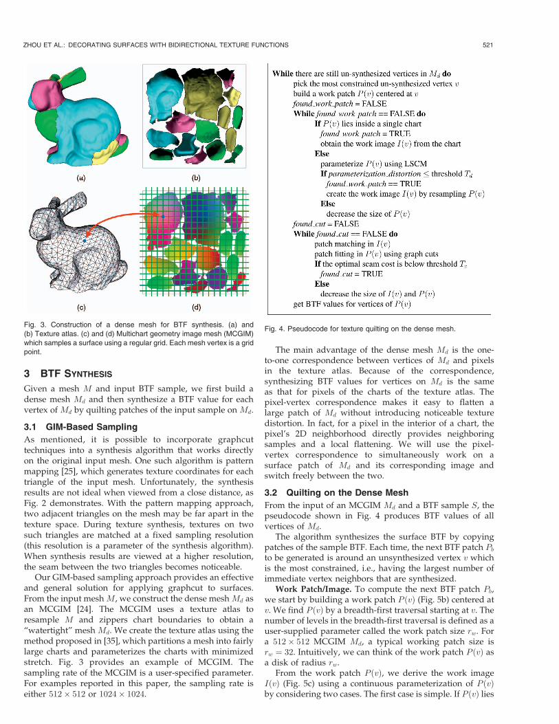
We present an algorithm for quilting BTF patches byusing graphcut [3], [17] to minimize the discontinuity acrosspatch seams on arbitrary surface meshes. A straightforwardextension of graphcut to hierarchical pattern mapping [25] canbe used to generate texture coordinates for each triangle ofthe mesh. However, this would lead to textures that revealpatch seams when viewed close up. This could be apotential problem for any attempt to apply graphcut onsurfaces. Our algorithm solves this problem by denselyresampling the surfaces using geometry images [12]. Wecall this approach GIM-based sampling. Specifically, givenan input mesh, we create a dense mesh by densely samplingthe input mesh using multichart geometry images(MCGIM) [24]. The texture synthesis is accomplished byusing graphcut to generate texture coordinates for eachvertex of the dense mesh. Because a texture value iscomputed for each vertex of the dense mesh, the synthe-sized textures can be viewed from any distance just likethose obtained with pixel-based algorithms (e.g., [26]). Fig. 2compares the results of the GIM-based sampling approachwith a straightforward extension of graphcut to [25].
The second challenge we face is finding a user-friendlyway to introduce irregular features into a backgroundpattern. Graphcut techniques suggest a straightforwardapproach to merging a foreground feature with the back-ground pattern, i.e., we simply constrain the feature to adesired location and use graphcut to find the merging seam.However, this approach only supports verbatim copying ofexisting features. To allow the user to generate new features, weformulate the constrained graphcut problem for texture andBTF painting. For texture synthesis, only smoothness energyis considered for finding seams that minimize discontinuity[17]. For texture painting, both smoothness and constraintenergies are used so that the user’s specification of the newfeature is incorporated into the graphcut problem asconstraints. Generating a new feature with the graphcutpainting algorithm is easy. The user only needs to specify therough shape and location of the desired new feature; oursystem will synthesize the actual feature and have it mergedseamlessly with the background pattern.
We demonstrate the effectiveness of our system with avariety of examples. Note that our techniques work forordinary color textures, which may be regarded as BTFswith a single viewing direction and a single lightingdirection.
2 RELATED WORK
Texture Synthesis. Algorithms for synthesizing textures on
surfaces can bedivided into two categories. The first category
[11], [27], [29], [32], [26], [33], [34] is based on per-pixel
nonparametric sampling [9], [28]. Per-pixel sampling is
susceptible to the problems caused by the fact that the
commonly used L2-norm is a poor measure of perceptual
similarity. For this reason, algorithms in this category have
difficulty maintaining texture patterns with certain types for
textures [1], [14], [34]. Currently, there is no general solution,
but remedies exist for various specific scenarios [1], [34].Algorithms in the second category synthesize textures by
copying patches of the input texture sample. Since texture
patterns are directly copied onto the target surface, these
algorithms are not seriously affected by the issue with the
L2-norm. Earlier algorithms randomly paste patches and
use alpha-blending to hide patch seams [23], [31]. Quilting
[8], [19], [25], [21], [17] generates significantly better results
by carefully placing patches to minimize the discontinuity
across patch seams. After placing patches, [19], [21] simply
use alpha-blending to hide patch seams, while [8], [17]
further enhance the smoothness across the seams by
searching for the “min-cut” seams.For image textures, [17] recently demonstrated that
quilting with graphcut arguably produces the best results
on the largest variety of textures. In this paper, we show
how to perform graphcut on surfaces.Decorating Surfaces. For decorating implicit surfaces,
[22] proposed a set of texturing operations which include
tiling and positioning of small images onto surfaces.
Igarashi and Cosgrove [15], Foskey et al. [10], and Carr
and Hart [4] presented several 3D surface painting systems.
For decorating surfaces with imperfections, existing techni-
ques (e.g., [2], [30], [7]) mostly focus on generating synthetic
surface imperfections. Complementary to their approaches,
our techniques synthesize imperfections from real-world
and synthetic samples.
520 IEEE TRANSACTIONS ON VISUALIZATION AND COMPUTER GRAPHICS, VOL. 11, NO. 5, SEPTEMBER/OCTOBER 2005
Fig. 1. Decorating arbitrary surfaces using BTFs. Left: Result of BTF
synthesis. Right: Result after introducing surface imperfections into the
homogeneous BTF shown on the left.
Fig. 2. A straightforward extension of graphcut to [25] leads tosuboptimal quality when the synthesis results are viewed from a closedistance, as the results in the middle column demonstrate. These resultsare obtained by incorporating graphcut into [25], which works directly onthe original input mesh (left column, top). Notice the patch seams. Theright column shows results produced by the GIM-based samplingapproach. The input texture sample is shown in the left column (bottom).
3 BTF SYNTHESIS
Given a mesh M and input BTF sample, we first build adense mesh Md and then synthesize a BTF value for eachvertex of Md by quilting patches of the input sample on Md.
3.1 GIM-Based Sampling
As mentioned, it is possible to incorporate graphcuttechniques into a synthesis algorithm that works directlyon the original input mesh. One such algorithm is patternmapping [25], which generates texture coordinates for eachtriangle of the input mesh. Unfortunately, the synthesisresults are not ideal when viewed from a close distance, asFig. 2 demonstrates. With the pattern mapping approach,two adjacent triangles on the mesh may be far apart in thetexture space. During texture synthesis, textures on twosuch triangles are matched at a fixed sampling resolution(this resolution is a parameter of the synthesis algorithm).When synthesis results are viewed at a higher resolution,the seam between the two triangles becomes noticeable.
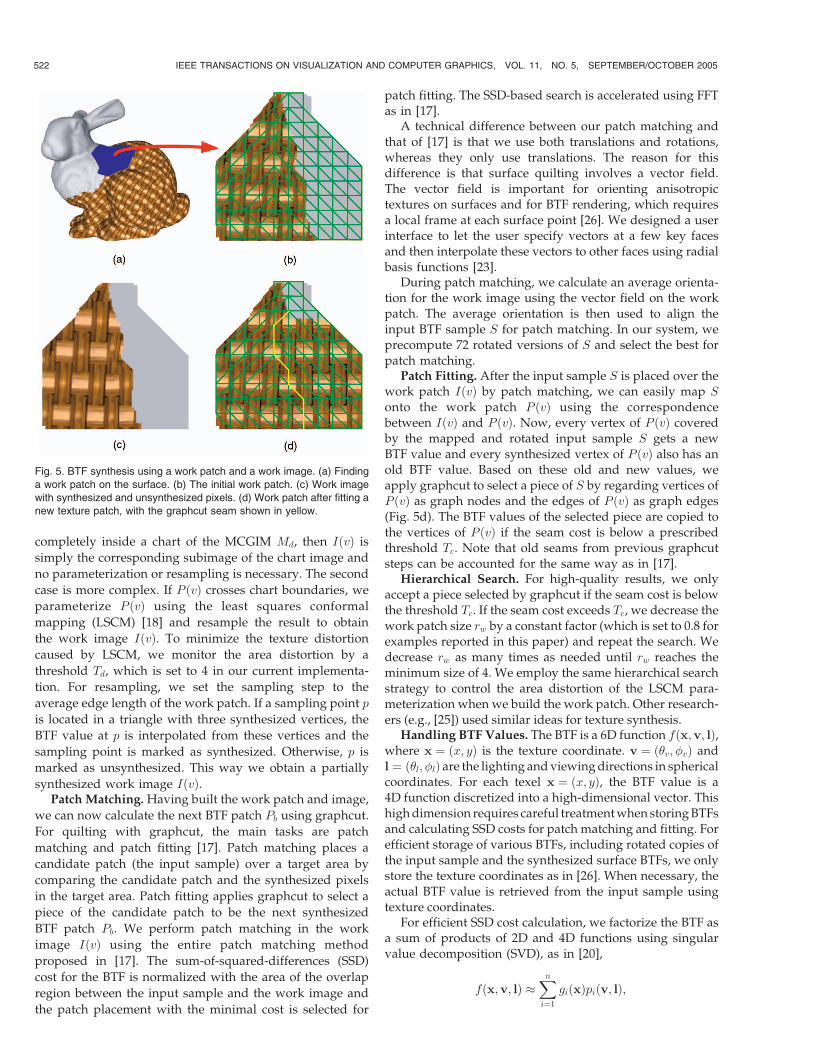
Our GIM-based sampling approach provides an effectiveand general solution for applying graphcut to surfaces.From the input meshM, we construct the dense meshMd asan MCGIM [24]. The MCGIM uses a texture atlas toresample M and zippers chart boundaries to obtain a“watertight” mesh Md. We create the texture atlas using themethod proposed in [35], which partitions a mesh into fairlylarge charts and parameterizes the charts with minimizedstretch. Fig. 3 provides an example of MCGIM. Thesampling rate of the MCGIM is a user-specified parameter.For examples reported in this paper, the sampling rate iseither 512� 512 or 1024� 1024.
The main advantage of the dense mesh Md is the one-to-one correspondence between vertices of Md and pixelsin the texture atlas. Because of the correspondence,synthesizing BTF values for vertices on Md is the sameas that for pixels of the charts of the texture atlas. Thepixel-vertex correspondence makes it easy to flatten alarge patch of Md without introducing noticeable texturedistortion. In fact, for a pixel in the interior of a chart, thepixel’s 2D neighborhood directly provides neighboringsamples and a local flattening. We will use the pixel-vertex correspondence to simultaneously work on asurface patch of Md and its corresponding image andswitch freely between the two.
3.2 Quilting on the Dense Mesh
From the input of an MCGIM Md and a BTF sample S, thepseudocode shown in Fig. 4 produces BTF values of allvertices of Md.
The algorithm synthesizes the surface BTF by copyingpatches of the sample BTF. Each time, the next BTF patch Pb
to be generated is around an unsynthesized vertex v whichis the most constrained, i.e., having the largest number ofimmediate vertex neighbors that are synthesized.
Work Patch/Image. To compute the next BTF patch Pb,we start by building a work patch P ðvÞ (Fig. 5b) centered atv. We find P ðvÞ by a breadth-first traversal starting at v. Thenumber of levels in the breadth-first traversal is defined as auser-supplied parameter called the work patch size rw. Fora 512� 512 MCGIM Md, a typical working patch size isrw ¼ 32. Intuitively, we can think of the work patch P ðvÞ asa disk of radius rw.
From the work patch P ðvÞ, we derive the work imageIðvÞ (Fig. 5c) using a continuous parameterization of P ðvÞby considering two cases. The first case is simple. If P ðvÞ lies
ZHOU ET AL.: DECORATING SURFACES WITH BIDIRECTIONAL TEXTURE FUNCTIONS 521
Fig. 3. Construction of a dense mesh for BTF synthesis. (a) and
(b) Texture atlas. (c) and (d) Multichart geometry image mesh (MCGIM)
which samples a surface using a regular grid. Each mesh vertex is a grid
point.
Fig. 4. Pseudocode for texture quilting on the dense mesh.
completely inside a chart of the MCGIM Md, then IðvÞ is
simply the corresponding subimage of the chart image and
no parameterization or resampling is necessary. The second
case is more complex. If P ðvÞ crosses chart boundaries, we
parameterize P ðvÞ using the least squares conformal
mapping (LSCM) [18] and resample the result to obtain
the work image IðvÞ. To minimize the texture distortion
caused by LSCM, we monitor the area distortion by a
threshold Td, which is set to 4 in our current implementa-
tion. For resampling, we set the sampling step to the
average edge length of the work patch. If a sampling point p
is located in a triangle with three synthesized vertices, the
BTF value at p is interpolated from these vertices and the
sampling point is marked as synthesized. Otherwise, p is
marked as unsynthesized. This way we obtain a partially
synthesized work image IðvÞ.Patch Matching.Having built the work patch and image,
we can now calculate the next BTF patch Pb using graphcut.
For quilting with graphcut, the main tasks are patch
matching and patch fitting [17]. Patch matching places a
candidate patch (the input sample) over a target area by
comparing the candidate patch and the synthesized pixels
in the target area. Patch fitting applies graphcut to select a
piece of the candidate patch to be the next synthesized
BTF patch Pb. We perform patch matching in the work
image IðvÞ using the entire patch matching method
proposed in [17]. The sum-of-squared-differences (SSD)
cost for the BTF is normalized with the area of the overlap
region between the input sample and the work image and
the patch placement with the minimal cost is selected for
patch fitting. The SSD-based search is accelerated using FFTas in [17].
A technical difference between our patch matching andthat of [17] is that we use both translations and rotations,whereas they only use translations. The reason for thisdifference is that surface quilting involves a vector field.The vector field is important for orienting anisotropictextures on surfaces and for BTF rendering, which requiresa local frame at each surface point [26]. We designed a userinterface to let the user specify vectors at a few key facesand then interpolate these vectors to other faces using radialbasis functions [23].
During patch matching, we calculate an average orienta-tion for the work image using the vector field on the workpatch. The average orientation is then used to align theinput BTF sample S for patch matching. In our system, weprecompute 72 rotated versions of S and select the best forpatch matching.
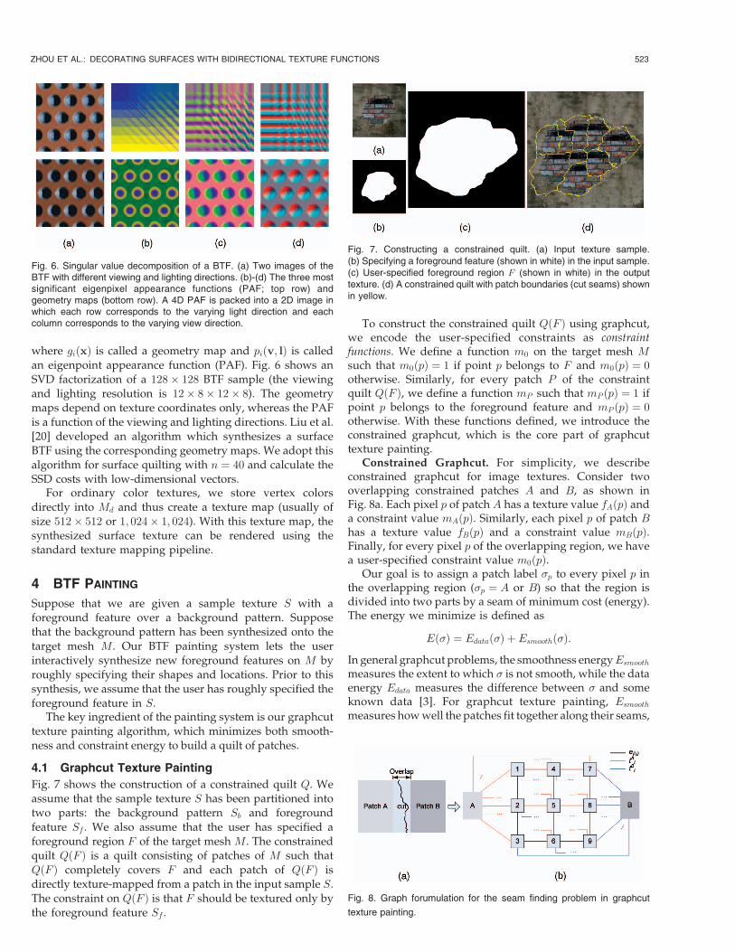
Patch Fitting. After the input sample S is placed over thework patch IðvÞ by patch matching, we can easily map S
onto the work patch P ðvÞ using the correspondencebetween IðvÞ and P ðvÞ. Now, every vertex of P ðvÞ coveredby the mapped and rotated input sample S gets a newBTF value and every synthesized vertex of P ðvÞ also has anold BTF value. Based on these old and new values, weapply graphcut to select a piece of S by regarding vertices ofP ðvÞ as graph nodes and the edges of P ðvÞ as graph edges(Fig. 5d). The BTF values of the selected piece are copied tothe vertices of P ðvÞ if the seam cost is below a prescribedthreshold Tc. Note that old seams from previous graphcutsteps can be accounted for the same way as in [17].
Hierarchical Search. For high-quality results, we onlyaccept a piece selected by graphcut if the seam cost is belowthe threshold Tc. If the seam cost exceeds Tc, we decrease thework patch size rw by a constant factor (which is set to 0.8 forexamples reported in this paper) and repeat the search. Wedecrease rw as many times as needed until rw reaches theminimum size of 4. We employ the same hierarchical searchstrategy to control the area distortion of the LSCM para-meterization when we build the work patch. Other research-ers (e.g., [25]) used similar ideas for texture synthesis.
Handling BTF Values. The BTF is a 6D function fðx;v; lÞ,where x ¼ ðx; yÞ is the texture coordinate. v ¼ ð�v; �vÞ andl ¼ ð�l; �lÞ are the lighting andviewingdirections in sphericalcoordinates. For each texel x ¼ ðx; yÞ, the BTF value is a4D function discretized into a high-dimensional vector. Thishighdimension requires careful treatmentwhen storingBTFsand calculating SSD costs for patch matching and fitting. Forefficient storage of various BTFs, including rotated copies ofthe input sample and the synthesized surface BTFs, we onlystore the texture coordinates as in [26]. When necessary, theactual BTF value is retrieved from the input sample usingtexture coordinates.
For efficient SSD cost calculation, we factorize the BTF asa sum of products of 2D and 4D functions using singularvalue decomposition (SVD), as in [20],
fðx;v; lÞ �Xni¼1
giðxÞpiðv; lÞ;
522 IEEE TRANSACTIONS ON VISUALIZATION AND COMPUTER GRAPHICS, VOL. 11, NO. 5, SEPTEMBER/OCTOBER 2005
Fig. 5. BTF synthesis using a work patch and a work image. (a) Finding
a work patch on the surface. (b) The initial work patch. (c) Work image
with synthesized and unsynthesized pixels. (d) Work patch after fitting a
new texture patch, with the graphcut seam shown in yellow.
where giðxÞ is called a geometry map and piðv; lÞ is calledan eigenpoint appearance function (PAF). Fig. 6 shows anSVD factorization of a 128� 128 BTF sample (the viewingand lighting resolution is 12� 8� 12� 8). The geometrymaps depend on texture coordinates only, whereas the PAFis a function of the viewing and lighting directions. Liu et al.[20] developed an algorithm which synthesizes a surfaceBTF using the corresponding geometry maps. We adopt thisalgorithm for surface quilting with n ¼ 40 and calculate theSSD costs with low-dimensional vectors.
For ordinary color textures, we store vertex colorsdirectly into Md and thus create a texture map (usually ofsize 512� 512 or 1; 024� 1; 024). With this texture map, thesynthesized surface texture can be rendered using thestandard texture mapping pipeline.
4 BTF PAINTING
Suppose that we are given a sample texture S with aforeground feature over a background pattern. Supposethat the background pattern has been synthesized onto thetarget mesh M. Our BTF painting system lets the userinteractively synthesize new foreground features on M byroughly specifying their shapes and locations. Prior to thissynthesis, we assume that the user has roughly specified theforeground feature in S.
The key ingredient of the painting system is our graphcuttexture painting algorithm, which minimizes both smooth-ness and constraint energy to build a quilt of patches.
4.1 Graphcut Texture Painting
Fig. 7 shows the construction of a constrained quilt Q. Weassume that the sample texture S has been partitioned intotwo parts: the background pattern Sb and foregroundfeature Sf . We also assume that the user has specified aforeground region F of the target mesh M. The constrainedquilt QðF Þ is a quilt consisting of patches of M such thatQðF Þ completely covers F and each patch of QðF Þ isdirectly texture-mapped from a patch in the input sample S.The constraint on QðF Þ is that F should be textured only bythe foreground feature Sf .
To construct the constrained quilt QðF Þ using graphcut,we encode the user-specified constraints as constraintfunctions. We define a function m0 on the target mesh Msuch that m0ðpÞ ¼ 1 if point p belongs to F and m0ðpÞ ¼ 0otherwise. Similarly, for every patch P of the constraintquilt QðF Þ, we define a function mP such that mP ðpÞ ¼ 1 ifpoint p belongs to the foreground feature and mP ðpÞ ¼ 0otherwise. With these functions defined, we introduce theconstrained graphcut, which is the core part of graphcuttexture painting.
Constrained Graphcut. For simplicity, we describeconstrained graphcut for image textures. Consider twooverlapping constrained patches A and B, as shown inFig. 8a. Each pixel p of patch A has a texture value fAðpÞ anda constraint value mAðpÞ. Similarly, each pixel p of patch Bhas a texture value fBðpÞ and a constraint value mBðpÞ.Finally, for every pixel p of the overlapping region, we havea user-specified constraint value m0ðpÞ.
Our goal is to assign a patch label �p to every pixel p inthe overlapping region (�p ¼ A or B) so that the region isdivided into two parts by a seam of minimum cost (energy).The energy we minimize is defined as
Eð�Þ ¼ Edatað�Þ þ Esmoothð�Þ:
In general graphcut problems, the smoothness energyEsmooth
measures the extent to which � is not smooth, while the dataenergy Edata measures the difference between � and someknown data [3]. For graphcut texture painting, Esmooth
measures howwell the patches fit together along their seams,
ZHOU ET AL.: DECORATING SURFACES WITH BIDIRECTIONAL TEXTURE FUNCTIONS 523
Fig. 6. Singular value decomposition of a BTF. (a) Two images of theBTF with different viewing and lighting directions. (b)-(d) The three mostsignificant eigenpixel appearance functions (PAF; top row) andgeometry maps (bottom row). A 4D PAF is packed into a 2D image inwhich each row corresponds to the varying light direction and eachcolumn corresponds to the varying view direction.
Fig. 7. Constructing a constrained quilt. (a) Input texture sample.(b) Specifying a foreground feature (shown in white) in the input sample.(c) User-specified foreground region F (shown in white) in the outputtexture. (d) A constrained quilt with patch boundaries (cut seams) shownin yellow.
Fig. 8. Graph forumulation for the seam finding problem in graphcut
texture painting.
whereas Edata ¼ Econstraint measures how well the synthe-sized texture satisfies the user specified constraintm0.
Fitting patches together while minimizing Esmooth alongthe seams is done the same way as graphcut texturesynthesis [17]. The energy Esmooth is defined as in [3]:
Esmoothð�Þ ¼Xp;q
Vðp;qÞð�p; �qÞ;
whereP
p;q is the sum over all pairs of adjacent pixels in theoverlapping region. The smoothness function Vðp;qÞð�p; �qÞ isdefined as
Vðp;qÞð�p; �qÞ ¼ jjf�pðpÞ � f�qðpÞjj þ jjf�pðqÞ � f�q ðqÞjj;
where fAðpÞ and fBðpÞ are pixel p’s texture values forpatches A and B, respectively.
For graphcut texture painting, we need to further satisfythe user-specified constraint m0. This is where graphcuttexture painting differs from graphcut texture synthesis,which uses Esmooth only. We incorporate the user-specifiedconstraint into quilting by making use of the energy Edata,defined as
Edatað�Þ ¼ Econstraintð�Þ ¼Xp
Dpð�pÞ;
whereP
p is the sum over all pixels in the overlappingregion. The function Dpð�pÞ is defined as:
Dpð�pÞ ¼ jjm�pðpÞ �m0ðpÞjj;
where m�pðpÞ is the constraint value of patch �p at pixel p,while m0ðpÞ is the user-specified constraint value at pixel p.
We use the optimal swap move approach [3] to minimizethe energy Eð�Þ. Fig. 8b illustrates the graph construction.The nodes of the graph consist of all pixels in theoverlapping region and two terminals A and B. Each pixelp in the overlapping region is connected to the terminals Aand B by edges tAp and tBp , respectively. These edges arereferred to as t-links (terminal links). Each pair of theadjacent pixels ðp; qÞ in the overlapping region is connectedby an edge eðp;qÞ, called an n-link (neighbor link). Theweights of the edges are
weightðtAp Þ ¼ DpðAÞ; weightðtBp Þ ¼ DpðBÞweightðeðp;qÞÞ ¼ Vðp;qÞðA;BÞ:
Applying the min-cut algorithm to the constructed graphproduces the minimum cost cut that separates node A fromnode B. As explained in [3], any cut in the graph mustinclude exactly one t-link for any pixel p. Thus, any cutleaves each pixel p in the overlapping region with exactlyone t-link, which defines a natural label �p according to theminimum cost cut C,
�p ¼A tAp 2 C
B tBp 2 C:
(
The approach for handling old seams in graphcut texturesynthesis also works with graphcut texture painting.
Quilting on Surfaces. The surface quilting algorithmdescribed in Section 3 can be adopted for graphcut texturepainting on surfaces with modifications of the patch
matching and fitting steps. For patch matching, we useboth the BTF values and the constraint values (ms and m0
values) to perform a joint search for optimal patchplacement. For patch fitting, we use constrained graphcut.
4.2 Painting System
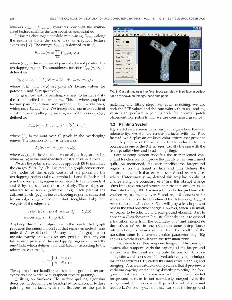
Fig. 9 exhibits a screenshot of our painting system. For userinteractivity, we do not render surfaces with the BTF.Instead, we display an ordinary color texture that providesa quick preview of the actual BTF. The color texture isobtained as one of the BTF images (usually the one with thefront parallel view and head-on lighting).
Our painting system modifies the user-specified con-straint functionm0 to improve the quality of the constrainedquilt. As mentioned, the user specifies the foregroundregion F on the target surface and thus defines theconstraint m0 such that m0 ¼ 1 over F and m0 ¼ 0 else-where. Unfortunately, m0 defined this way has an abruptchange along the boundary of F and this abrupt changeoften leads to destroyed texture patterns in nearby areas, asillustrated in Fig. 10f. A naive solution to this problem is toweaken m0 as m0 ¼ � over F and m0 ¼ 0 elsewhere forsome small �. From the definition of the data energy Edata, ifm0 is set to a small value �, Edata will play a less importantrole in the total objective energy. However, when � is small,m0 ceases to be effective and background elements start toappear in F , as shown in Fig. 10e. Our solution is to expanda transition zone from the boundary of F and interpolatethe values of m0 in the transition zone using linearinterpolation, as shown in Fig. 10d. The width of thetransition zone is a user-adjustable parameter. Fig. 10gshows a synthesis result with the transition zone.
In addition to synthesizing new foreground features, oursystem also supports verbatim copying of the foregroundfeature from the input sample onto the surface. This is astraightforward extension of the verbatim copying techniquefor image textures ([17] called this interactive blending andmerging). A useful feature of our system is that it previews averbatim copying operation by directly projecting the fore-ground feature onto the surface. Although the projectedforeground feature is not seamlessly merged with thebackground, the preview still provides valuable visualfeedback. With our system, the user can slide the foreground
524 IEEE TRANSACTIONS ON VISUALIZATION AND COMPUTER GRAPHICS, VOL. 11, NO. 5, SEPTEMBER/OCTOBER 2005
Fig. 9. Our painting user interface. Input samples with surface imperfec-
tions are shown on the right-hand side panel.
feature on the surface to find a desired pasting location
since the foreground feature can be mapped onto the
surface extremely quickly using the work patch/image at
the target location.
5 RESULTS
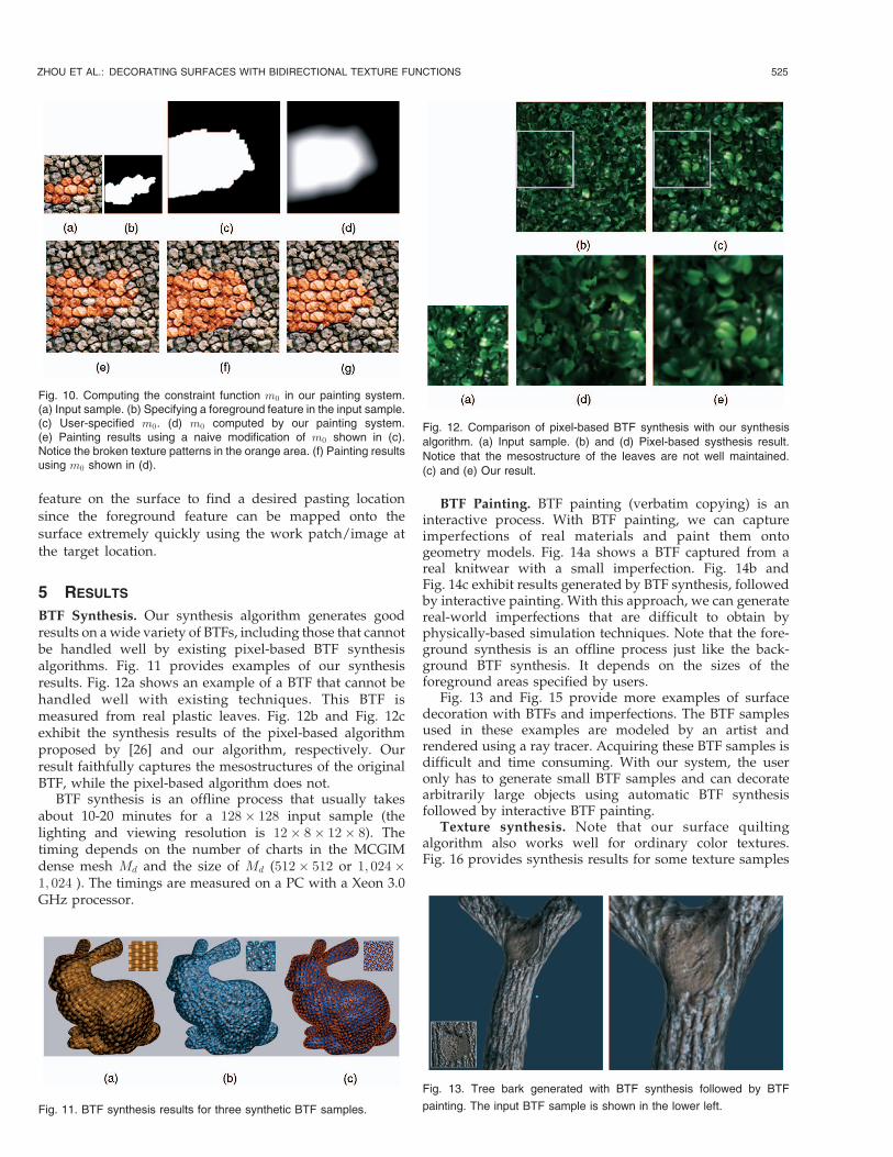
BTF Synthesis. Our synthesis algorithm generates goodresults on awide variety of BTFs, including those that cannotbe handled well by existing pixel-based BTF synthesisalgorithms. Fig. 11 provides examples of our synthesisresults. Fig. 12a shows an example of a BTF that cannot behandled well with existing techniques. This BTF ismeasured from real plastic leaves. Fig. 12b and Fig. 12cexhibit the synthesis results of the pixel-based algorithmproposed by [26] and our algorithm, respectively. Ourresult faithfully captures the mesostructures of the originalBTF, while the pixel-based algorithm does not.
BTF synthesis is an offline process that usually takesabout 10-20 minutes for a 128� 128 input sample (thelighting and viewing resolution is 12� 8� 12� 8). Thetiming depends on the number of charts in the MCGIMdense mesh Md and the size of Md (512� 512 or 1; 024�1; 024 ). The timings are measured on a PC with a Xeon 3.0GHz processor.
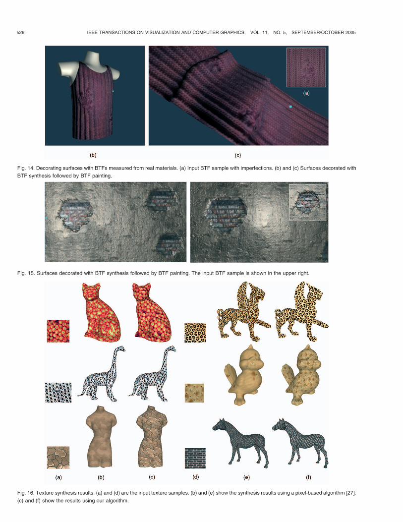
BTF Painting. BTF painting (verbatim copying) is aninteractive process. With BTF painting, we can captureimperfections of real materials and paint them ontogeometry models. Fig. 14a shows a BTF captured from areal knitwear with a small imperfection. Fig. 14b andFig. 14c exhibit results generated by BTF synthesis, followedby interactive painting. With this approach, we can generatereal-world imperfections that are difficult to obtain byphysically-based simulation techniques. Note that the fore-ground synthesis is an offline process just like the back-ground BTF synthesis. It depends on the sizes of theforeground areas specified by users.
Fig. 13 and Fig. 15 provide more examples of surfacedecoration with BTFs and imperfections. The BTF samplesused in these examples are modeled by an artist andrendered using a ray tracer. Acquiring these BTF samples isdifficult and time consuming. With our system, the useronly has to generate small BTF samples and can decoratearbitrarily large objects using automatic BTF synthesisfollowed by interactive BTF painting.
Texture synthesis. Note that our surface quiltingalgorithm also works well for ordinary color textures.Fig. 16 provides synthesis results for some texture samples
ZHOU ET AL.: DECORATING SURFACES WITH BIDIRECTIONAL TEXTURE FUNCTIONS 525
Fig. 11. BTF synthesis results for three synthetic BTF samples.
Fig. 12. Comparison of pixel-based BTF synthesis with our synthesis
algorithm. (a) Input sample. (b) and (d) Pixel-based systhesis result.
Notice that the mesostructure of the leaves are not well maintained.
(c) and (e) Our result.
Fig. 13. Tree bark generated with BTF synthesis followed by BTF
painting. The input BTF sample is shown in the lower left.
Fig. 10. Computing the constraint function m0 in our painting system.(a) Input sample. (b) Specifying a foreground feature in the input sample.(c) User-specified m0. (d) m0 computed by our painting system.(e) Painting results using a naive modification of m0 shown in (c).Notice the broken texture patterns in the orange area. (f) Painting resultsusing m0 shown in (d).
526 IEEE TRANSACTIONS ON VISUALIZATION AND COMPUTER GRAPHICS, VOL. 11, NO. 5, SEPTEMBER/OCTOBER 2005
Fig. 14. Decorating surfaces with BTFs measured from real materials. (a) Input BTF sample with imperfections. (b) and (c) Surfaces decorated with
BTF synthesis followed by BTF painting.
Fig. 15. Surfaces decorated with BTF synthesis followed by BTF painting. The input BTF sample is shown in the upper right.
Fig. 16. Texture synthesis results. (a) and (d) are the input texture samples. (b) and (e) show the synthesis results using a pixel-based algorithm [27].
(c) and (f) show the results using our algorithm.
with highly structured patterns, using both a pixel-based
algorithm [27] and our algorithm. For these texture samples,
the pixel-based algorithm always causes the texture
patterns to break apart, while our surface quilting algorithm
can preserve the integrity of texture patterns very well.
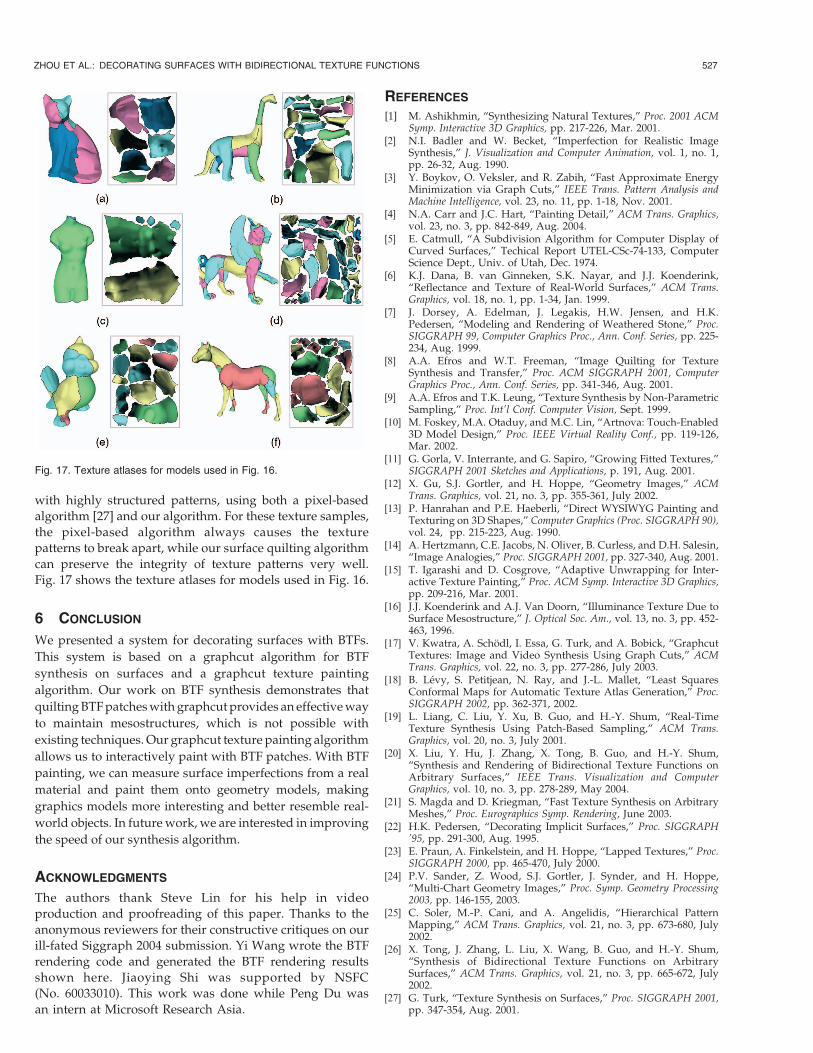
Fig. 17 shows the texture atlases for models used in Fig. 16.
6 CONCLUSION
We presented a system for decorating surfaces with BTFs.
This system is based on a graphcut algorithm for BTF
synthesis on surfaces and a graphcut texture painting
algorithm. Our work on BTF synthesis demonstrates that
quiltingBTFpatcheswith graphcutprovides aneffectiveway
to maintain mesostructures, which is not possible with
existing techniques. Our graphcut texture painting algorithm
allows us to interactively paint with BTF patches. With BTF
painting, we can measure surface imperfections from a real
material and paint them onto geometry models, making
graphics models more interesting and better resemble real-
world objects. In futurework, we are interested in improving
the speed of our synthesis algorithm.
ACKNOWLEDGMENTS
The authors thank Steve Lin for his help in video
production and proofreading of this paper. Thanks to the
anonymous reviewers for their constructive critiques on our
ill-fated Siggraph 2004 submission. Yi Wang wrote the BTF
rendering code and generated the BTF rendering results
shown here. Jiaoying Shi was supported by NSFC
(No. 60033010). This work was done while Peng Du was
an intern at Microsoft Research Asia.
REFERENCES
[1] M. Ashikhmin, “Synthesizing Natural Textures,” Proc. 2001 ACMSymp. Interactive 3D Graphics, pp. 217-226, Mar. 2001.
[2] N.I. Badler and W. Becket, “Imperfection for Realistic ImageSynthesis,” J. Visualization and Computer Animation, vol. 1, no. 1,pp. 26-32, Aug. 1990.
[3] Y. Boykov, O. Veksler, and R. Zabih, “Fast Approximate EnergyMinimization via Graph Cuts,” IEEE Trans. Pattern Analysis andMachine Intelligence, vol. 23, no. 11, pp. 1-18, Nov. 2001.
[4] N.A. Carr and J.C. Hart, “Painting Detail,” ACM Trans. Graphics,vol. 23, no. 3, pp. 842-849, Aug. 2004.
[5] E. Catmull, “A Subdivision Algorithm for Computer Display ofCurved Surfaces,” Techical Report UTEL-CSc-74-133, ComputerScience Dept., Univ. of Utah, Dec. 1974.
[6] K.J. Dana, B. van Ginneken, S.K. Nayar, and J.J. Koenderink,“Reflectance and Texture of Real-World Surfaces,” ACM Trans.Graphics, vol. 18, no. 1, pp. 1-34, Jan. 1999.
[7] J. Dorsey, A. Edelman, J. Legakis, H.W. Jensen, and H.K.Pedersen, “Modeling and Rendering of Weathered Stone,” Proc.SIGGRAPH 99, Computer Graphics Proc., Ann. Conf. Series, pp. 225-234, Aug. 1999.
[8] A.A. Efros and W.T. Freeman, “Image Quilting for TextureSynthesis and Transfer,” Proc. ACM SIGGRAPH 2001, ComputerGraphics Proc., Ann. Conf. Series, pp. 341-346, Aug. 2001.
[9] A.A. Efros and T.K. Leung, “Texture Synthesis by Non-ParametricSampling,” Proc. Int’l Conf. Computer Vision, Sept. 1999.
[10] M. Foskey, M.A. Otaduy, and M.C. Lin, “Artnova: Touch-Enabled3D Model Design,” Proc. IEEE Virtual Reality Conf., pp. 119-126,Mar. 2002.
[11] G. Gorla, V. Interrante, and G. Sapiro, “Growing Fitted Textures,”SIGGRAPH 2001 Sketches and Applications, p. 191, Aug. 2001.
[12] X. Gu, S.J. Gortler, and H. Hoppe, “Geometry Images,” ACMTrans. Graphics, vol. 21, no. 3, pp. 355-361, July 2002.
[13] P. Hanrahan and P.E. Haeberli, “Direct WYSIWYG Painting andTexturing on 3D Shapes,” Computer Graphics (Proc. SIGGRAPH 90),vol. 24, pp. 215-223, Aug. 1990.
[14] A. Hertzmann, C.E. Jacobs, N. Oliver, B. Curless, and D.H. Salesin,“Image Analogies,” Proc. SIGGRAPH 2001, pp. 327-340, Aug. 2001.
[15] T. Igarashi and D. Cosgrove, “Adaptive Unwrapping for Inter-active Texture Painting,” Proc. ACM Symp. Interactive 3D Graphics,pp. 209-216, Mar. 2001.
[16] J.J. Koenderink and A.J. Van Doorn, “Illuminance Texture Due toSurface Mesostructure,” J. Optical Soc. Am., vol. 13, no. 3, pp. 452-463, 1996.
[17] V. Kwatra, A. Schodl, I. Essa, G. Turk, and A. Bobick, “GraphcutTextures: Image and Video Synthesis Using Graph Cuts,” ACMTrans. Graphics, vol. 22, no. 3, pp. 277-286, July 2003.
[18] B. Levy, S. Petitjean, N. Ray, and J.-L. Mallet, “Least SquaresConformal Maps for Automatic Texture Atlas Generation,” Proc.SIGGRAPH 2002, pp. 362-371, 2002.
[19] L. Liang, C. Liu, Y. Xu, B. Guo, and H.-Y. Shum, “Real-TimeTexture Synthesis Using Patch-Based Sampling,” ACM Trans.Graphics, vol. 20, no. 3, July 2001.
[20] X. Liu, Y. Hu, J. Zhang, X. Tong, B. Guo, and H.-Y. Shum,“Synthesis and Rendering of Bidirectional Texture Functions onArbitrary Surfaces,” IEEE Trans. Visualization and ComputerGraphics, vol. 10, no. 3, pp. 278-289, May 2004.
[21] S. Magda and D. Kriegman, “Fast Texture Synthesis on ArbitraryMeshes,” Proc. Eurographics Symp. Rendering, June 2003.
[22] H.K. Pedersen, “Decorating Implicit Surfaces,” Proc. SIGGRAPH’95, pp. 291-300, Aug. 1995.
[23] E. Praun, A. Finkelstein, and H. Hoppe, “Lapped Textures,” Proc.SIGGRAPH 2000, pp. 465-470, July 2000.
[24] P.V. Sander, Z. Wood, S.J. Gortler, J. Synder, and H. Hoppe,“Multi-Chart Geometry Images,” Proc. Symp. Geometry Processing2003, pp. 146-155, 2003.
[25] C. Soler, M.-P. Cani, and A. Angelidis, “Hierarchical PatternMapping,” ACM Trans. Graphics, vol. 21, no. 3, pp. 673-680, July2002.
[26] X. Tong, J. Zhang, L. Liu, X. Wang, B. Guo, and H.-Y. Shum,“Synthesis of Bidirectional Texture Functions on ArbitrarySurfaces,” ACM Trans. Graphics, vol. 21, no. 3, pp. 665-672, July2002.
[27] G. Turk, “Texture Synthesis on Surfaces,” Proc. SIGGRAPH 2001,pp. 347-354, Aug. 2001.
ZHOU ET AL.: DECORATING SURFACES WITH BIDIRECTIONAL TEXTURE FUNCTIONS 527
Fig. 17. Texture atlases for models used in Fig. 16.
[28] L.-Y. Wei and M. Levoy, “Fast Texture Synthesis Using Tree-Structured Vector Quantization,” Proc. SIGGRAPH 2000, pp. 479-488, July 2000.
[29] L.-Y. Wei and M. Levoy, “Texture Synthesis over ArbitraryManifold Surfaces,” Proc. SIGGRAPH 2001, pp. 355-360, Aug.2001.
[30] T.-T. Wong, W.-Y. Ng, and P.-A. Heng, “A Geometry DependentTexture Generation Framework for Simulating Surface Imperfec-tions,” Proc. Eurographics Rendering Workshop 1997, pp. 139-150,June 1997.
[31] Y.Q. Xu, B. Guo, and H.Y. Shum, “Chaos Mosaic: Fast andMemory Efficient Texture Synthesis,” Microsoft Research Techni-cal Report MSR-TR-2000-32, Apr. 2000.
[32] L. Ying, A. Hertzmann, H. Biermann, and D. Zorin, “Texture andShape Synthesis on Surfaces,” Proc. 12th Eurographics WorkshopRendering, pp. 301-312, June 2001.
[33] S. Zelinka and M. Garland, “Interactive Texture Synthesis onSurfaces Using Jump Maps,” Proc. Eurographics Symp. Rendering:14th Eurographics Workshop Rendering, pp. 90-96, June 2003.
[34] J. Zhang, K. Zhou, L. Velho, B. Guo, and H.-Y. Shum, “Synthesisof Progressively Variant Textures on Arbitrary Surfaces,” ACMTrans. Graphics, vol. 22, no. 3, pp. 295-302, July 2003.
[35] K. Zhou, J. Snyder, B. Guo, and H.-Y. Shum, “Iso-Charts: Stretch-Driven Mesh Parameterization Using Spectral Analysis,” Proc.Symp. Geometry Processing 2004, pp. 47-56, 2004.
Kun Zhou received the BS and PhD degrees incomputer science from the Zhejiang Universityin 1997 and 2002, respectively. He works in theareas of geometry processing, texture synthesis/analysis, and real-time rendering. He is currentlyan associate researcher at Microsoft ResearchAsia.
Peng Du received the BS and MS degrees incomputer science from Zhejiang University in2000 and 2004, respectively. His researchinterest is texture synthesis.
Lifeng Wang received the PhD degree incomputer science from Zhejiang University in1999. He is a researcher at Microsoft ResearchAsia. During his PhD studies, his research isfocused on image-based rendering. His currentresearch interests include realistic modeling andrealtime rendering, online games, image-basedrendering, and computer vision.
Yasuyuki Matsushita received the BEng,MEng, and PhD degrees in electrical engineer-ing from the University of Tokyo in 1998, 2000,and 2003, respectively. Currently, he is anassociate researcher at Microsoft ResearchAsia. His research interests include photometricmethods in computer vision, image-based ren-dering, and modeling from images. He is amember of the IEEE.
Jiaoying Shi is a professor in the Department ofComputer Science and Engineering at ZhejiangUniversity. He is now the director of theAcademic Committee of State Key Lab ofComputer Aided Design and Computer Gra-phics. He is the deputy chairman of the ChinaImage and Graphics Association and the deputychairman of the China CAD and GraphicsSociety under the China Computer Federation.He is the representative of the Asia in Education
Committee of ACM SIGGRAPH. Since 1990, his works have beenconcentrated in computer graphics, visualization in scientific computing,and virtual environment. He has published more than 100 papers andfour books.
Baining Guo received the PhD and MS degreesfrom Cornell University and the BS degree fromBeijing University. He is a senior researcher atMicrosoft Research Asia, where he manages thegraphics group. Before joining Microsoft, he wasa senior staff researcher in the MicrocomputerResearch Labs at Intel Corporation in SantaClara, California. His research interests aremainly in the modeling and rendering areas,including texture synthesis, reflectance and
shading models, real-time rendering, natural phenomena, and geometrymodeling. He is an associate editor of the IEEE Transactions onVisualization and Computer Graphics. He was on the papers commit-tees of Pacific Graphics ’02-’04, IEEE Visualization ’04, ACM VRST ’04,and Graphics Interface ’05. He is a papers cochair of CGI ’05. He holdsmore than 20 granted and pending US patents.
Heung-Yeung Shum received the PhD degreein robotics from the School of ComputerScience, Carnegie Mellon University in 1996,after which he joined Microsoft Research Asia,where he is currently the managing director. Hisresearch interests are computer vision, compu-ter graphics, video representation, learning, andvisual recognition. Before joining Microsoft Re-search, he worked at Digital Equipment Corpor-ation’s Cambridge Research Lab, Apple
Computer’s Interactive Media Lab, and RealSpace, Inc. He holds morethan 20 US patents.
. For more information on this or any other computing topic,please visit our Digital Library at www.computer.org/publications/dlib.
528 IEEE TRANSACTIONS ON VISUALIZATION AND COMPUTER GRAPHICS, VOL. 11, NO. 5, SEPTEMBER/OCTOBER 2005