Embed Size (px)
Citation preview

Under consideration for publication in Theory and Practice of Logic Programming 1
Declarative Combinatorics: Exact CombinationalCircuit Synthesis in a Logic Programming
Framework
Paul TarauDept. of Computer Science and Engineering
University of North Texas, Denton, Texas, USA
E-mail: [email protected]
Brenda LudermanACES CAD
Lewisville, Texas, USAE-mail: [email protected]
submitted 1 January 2003; revised 1 January 2003; accepted 1 January 2003
Abstract
Logic Programming languages and combinational circuit synthesis tools share a common“combinatorial search over logic formulae” background. This paper attempts to reconnectthe two fields with a fresh look at Prolog encodings for the combinatorial objects involvedin circuit synthesis. While benefiting from Prolog’s fast unification algorithm and built-inbacktracking mechanism, efficiency of our search algorithm is ensured by using paral-lel bitstring operations together with logic variable equality propagation, as a mappingmechanism from primary inputs to the leaves of candidate DAGs implementing a com-binational circuit specification. Using a new exact synthesizer that automatically inducesminimal universal boolean function libraries, we introduce two indicators for comparingtheir expressiveness: the first, based on how many gates are used to synthesize all binaryoperators, the second based on how many N -variable truth table values are covered bycombining up to M gates from the library. By applying the indicators to an exhaustiveenumeration of minimal universal libraries, two dual asymmetrical operations, Logic Im-plication “⇒” and Half XOR “<” are found to consistently outperform their symmetricalcounterparts, NAND and NOR. Our expressiveness metrics bring support to the conjec-ture that asymmetrical operators are significantly more expressive that their well studiedsymmetric counterparts, omnipresent in various circuit design tools.
Keywords: logic programming and circuit design, exact combinational circuitsynthesis, asymmetrical logic operators, minimal universal boolean logic libraries,minimal transistor-count circuits
1 Introduction
Various logic programming applications and circuit synthesis tools share algorithmictechniques ranging from search over combinatorial objects and constraint solvingto symbolic rewriting and code transformations.

2 Paul Tarau and Brenda Luderman
The significant semantic distance between the two fields, coming partly from theapplication focus and partly from the hardware/software design gap has been alsowidened by the use of lower level procedural languages for implementing circuitdesign tools - arguably for providing better performance fine tuning opportunities.
While intrigued by the semantic and terminological gap between the two fields,our interest in the use of logic programming for circuit design has been encouragedbecause of the following facts:
• the simplicity and elegance of combinatorial generation algorithms in thecontext of Prolog’s backtracking, unification and logic grammar mechanisms
• the structural similarity between Prolog terms and the DAGs typically usedas a data structure for synthesized circuits
• elegant implementations of circuit design tools in high level functional lan-guages (O’Donnell )
• the presence of new flexible constraint solving Prolog extensions like CHR(Fruhwirth ) that could express layout, routing and technology mapping as-pects of the circuit design process needed, besides circuit synthesis, for realisticdesign tools.
The paper summarizes our efforts on solving some realistic combinational circuitsynthesis problems with logic programming tools.
Exact circuit synthesis has been a recurring topic of interest in circuit design,complexity theory, boolean logic, combinatorics and graph theory for more thanhalf a century (Knuth 2006; Shannon 1993; Oettinger and Aiken 1962; Davies 1957;Culliney et al. 1979; Lai and Muroga 1987). While its extreme intractability (typi-cally, single digit number of gates for most problems) could be an explanation forhaving attracted some of the best minds in the aforementioned research fields, ourmain reason for revisiting it in this paper is more practically driven.
Traditional silicon CMOS manufacturing relies often on hundreds of hand-madelibrary cells covering most of the gate combinations and transistor sizes used intypical circuits. As quantum effects leading to increased transistor leakage andnoise are getting harder and harder to circumvent for deep submicron designs (andoften involve using new materials and processes), porting such large libraries to thenew manufacturing technologies is labor intensive and costly.
Polymorphic or multi-functional circuits (Sekanina et al. 2006), often evolvedusing genetic programming have emerged (Sekanina 2006; Stoica et al. 2005). Withsuch circuits, that overlap digital logic with unconventional control parametersranging from voltage to temperature (Sekanina et al. 2006; Stoica et al. 2006) reuseof traditional libraries can be particularly difficult.
Further down the road, beyond the next decade, the advent of alternative circuitimplementations might involve radical departures from traditional CMOS processes,ranging from optical and quantum computing to biological or molecular techniques(Mira and Alvarez 2005). In some of these fields, manufacturability is likely to limitthe variety of gate-level building blocks. This also implies that the resulting librariesmight have to use as few as possible gates, involving unconventional, yet unknownprocesses.

Exact Circuit Synthesis in a Logic Programming Framework 3
Given a library of universal gates, the exact synthesis of boolean circuits consistsof finding minimal representation using only gates of the library.
Mentions of Prolog for circuit simulation go back as early as (Clocksin and Mellish1987). Peter Reintjes in (Reintjes 1992) mentions CMOS circuit design and Prologas two Elegant Technologies with potential for interaction.
Fairly efficient exact synthesis programs using symmetric operators have beendescribed as early as in (Davies 1957) and (Culliney et al. 1979). Knuth in (Knuth2006), section 7.1.2 mentions asymmetric operators like A < B as forming one ofthe 5 (out of 16) boolean functions used as part of a boolean chain (sequence ofconnected 2-argument boolean functions) needed for synthesis by exhaustive enu-meration. Interestingly, the other 4 are: >, ∗, +,⊕. Note that > is the symmetricof <, and that with its exception, ∗, +,⊕ have been heavily used in various syn-thesis algorithms. Knuth also computes minimal representations of all 5-argumentfunctions using a clever reduction to equivalence classes.
Rewriting/simplification has been used in various forms in recent work on multi-level synthesis (Mishchenko and Brayton 2002; Mishchenko and Sasao 2002) usingnon-SOP encodings ranging from And-Inverter Gates (AIGs) and XOR-AND netsto graph-based representations in the tradition of (Bryant 1986). While not explic-itly implying the use of the asymmetrical operators < and ⇒, AIGs can be used toimplicitly express them, given that A < B is equivalent to ∼ A ∗ B and A⇒ B isequivalent to ∼ (A∗ ∼ B)).
Interestingly, new synthesis targets, ranging from AIGs to cyclic combinationalcircuits (Riedel 2004), turned out to be competitive with more traditional minimiza-tion based synthesis techniques. Synthesis of reversible circuits with possible usesin low-power adiabatic computing and quantum computing (Shende et al. 2003;Maslov et al. 2005; Maslov et al. 2007; Maslov et al. 2005) have emerged. Despiteits super-exponential complexity, exact circuit synthesis efforts have been reportedsuccessful for increasingly large circuits (Drechsler and Gunther 1998; Knuth 2006).
This paper extends our recent work on the use of a logic programming frameworkfor circuit synthesis described in (Tarau and Luderman 2007; Tarau and Luder-man 2008b) by replacing the fixed library/Leaf DAG based algorithm with a moregeneral DAG-based algorithm (Tarau and Luderman 2008a), configurable to sup-port libraries given as run-time parameters. The new algorithm supports synthesisof multiple output functions and it is also faster, as it optimizes execution timethrough aggressive constraint propagation.
We implement full automation of exact synthesis tasks, covering automated dis-covery of universal libraries and a priori estimation of tractability of a given prob-lem, with special focus on circuit types likely to be relevant for nano-scale processes.
While the quantitative expressiveness comparison of two libraries can be solvedthrough exact synthesis for the small cases when it is tractable, the challenge isto extend this to the intractable cases that appear in practical design. We achievethis with two indicators for comparing their expressiveness: the first based on howmany gates are used to synthesize all binary operators, the second based on howmany N -variable truth table values are covered by combining up to M gates fromthe library.

4 Paul Tarau and Brenda Luderman
By applying the indicators to an exhaustive enumeration of minimal universallibraries, two dual asymmetrical operations, Logic Implication “⇒” and Half XOR“<” are found to consistently outperform their symmetrical counterparts, NANDand NOR, leading to the conjecture that asymmetrical operators are significantlymore expressive that their well studied symmetric counterparts, omnipresent in var-ious circuit design tools.
2 Exact Combinational Circuit Synthesis as Combinatorial Generation+ Constraint Propagation
Our exact synthesis algorithm uses depth-first backtracking and constraint propa-gation to find minimal N-input, M-output circuits representing boolean functions,based on a given library of operators and constants.
Synthesis Algorithm
1. First, obtain an output specification from a symbolic formula and compute aconservative upper limit (in terms of a cost function, for instance the numberof gates) on the size of the synthesized expression.
2. Next, enumerate candidate circuits (represented as directed acyclic graphs)in increasing cost order, to ensure that minimal circuits are generated first.This involves the following steps:
(a) Encode constants 0,1 and N primary input variables as bitstrings of size2N representing truth tables as described at the end of this section
(b) Initialize the list of available gates as being the set of primary inputs.(c) Until a maximum number of gates is reached, connect a new gate’s inputs
to the previously constructed gates’ outputs. The nondeterministic choiceof a new gate’s connections is a combinatorial step that is implementedefficiently using backtracking and constraint propagation. The computa-tion of the outputs is also combinatorial, with respect to using any ofthe possible gates in the library that match the constraints. At each stepconstraints are generated and checked as follows:
i propagate back the known values of the primary outputs to candidategates
ii compute the values of the outputs as bitstrings encoding all bit com-binations, as soon as their inputs are known
iii ensure that all gate outputs are distinct3. On success, the resulting circuit is decoded into a symbolic expression consist-
ing of a list of primary input variables, a list of gates describing the operatorsand their input and output arguments, and a list of primary output variables.
4. At the end, the following assertions hold:(a) The symbolic expression is guaranteed to evaluate to the list of truth tables
provided initially or obtained by evaluation of a given boolean expression.(b) The list of gates is guaranteed to be minimal, given that circuits are gen-
erated in increasing gate order.
Exact Circuit Synthesis in a Logic Programming Framework 5
Delay-Constrained Minimal Circuit Synthesis Given the uniform gate structure ofthe circuits, we can ensure that delays are within acceptable margins by simplyconstraining the maximum length of the longest path from the primary inputs tothe primary outputs.
Fanout restrictions Given that fanout restrictions can add only constant depthand size increases (Hoover et al. 1984) the tool currently focuses on exact synthesisassuming unbound fanout and binary operator libraries.
Synthesizing Minimal Universal Libraries Most minimal universal boolean functionlibraries have been discovered and documented in fields ranging from symbolic logicand complexity theory to circuit design. However, as they were needed as input forevaluating expressiveness of various libraries, we decided to induce them and provetheir minimality automatically by adapting our synthesis algorithm as follows:
1. Encode the 2N binary operators as integers from 0 to 2N − 1 based on thevalue columns of their truth tables (seen as bitstrings)
2. Generate candidate libraries as subsets of K operators for increasing valuesof K (extended progressively with 0 to 2 constant functions in the set {0,1})
3. Try out each candidate library if it can synthesize any of the well knownuniversal functions NAND,NOR
4. for each library of size N that passes the universality test, ensure that it isminimal, i.e.
(a) generate each of its sub-libraries of size N-1(b) discard the candidate library if any of its sub-libraries has been already
found as being universal(c) otherwise accumulate the newly found universal library in the result set
and use it to reject libraries having it as a sub-library later
3 The Prolog Implementation
We will start by overviewing the set of predicates dealing with boolean operationsefficiently.
3.1 Boolean Operations with Bitstring Truth Table Encodings
Evaluation of a boolean function can be performed one value at a time as in thepredicate if then else/4
if_then_else(X,Y,Z,R):-
bit(X),bit(Y),bit(Z),
( X==1→R=Y; R=Z).
bit(0).
bit(1).

6 Paul Tarau and Brenda Luderman
resulting in a truth table1
?- if_then_else(X,Y,Z,R),write([X,Y,Z]:R),nl,fail;nl.
[0, 0, 0]:0
[0, 0, 1]:1
[0, 1, 0]:0
[0, 1, 1]:1
[1, 0, 0]:0
[1, 0, 1]:0
[1, 1, 0]:1
[1, 1, 1]:1
Clearly, this does not take advantage of the ability of modern hardware to performsuch operations one word a time - with the instant benefit of a speed-up propor-tional to the word size. An alternate representation, adapted from (Knuth 2006)uses integer encodings of 2n bits for each boolean variable X0, . . . , Xn−1. Bitvectoroperations evaluate all value combinations at once.
Proposition 1Let xk be a variable for 0 ≤ k < n where n is the number of distinct variables ina boolean expression. Then column k in the matrix representation of the inputs inthe the truth table represents, as a bitstring, the natural number:
xk = (22n
− 1)/(22n−k−1+ 1) (1)
For instance, if n = 2, the formula computes x0 = 3 = [0, 0, 1, 1] and x1 = 5 =[0, 1, 0, 1].
The following predicates, working with arbitrary length bitstrings are used toevaluate variables xk with k ∈ [0..n − 1] with formula 1. we start by mappingthe constant boolean function 1 to the bitstring of length 2n, 111..1, representing22n − 1
all_ones_mask(NbOfBits,Mask):-Mask is (1<<(1<<NbOfBits))-1.
Then we proceed with the computation of xk, for a given number of bits:
var_to_bitstring_int(NbOfBits,K,Xk):-
all_ones_mask(NbOfBits,Mask),
NK is NbOfBits-(K+1),D is (1<<(1<<NK))+1,Xk is Mask//D.
The formula used in var to bitstring int, is an adaptation of the efficient bitstring-integer encoding described in the Boolean Evaluation section of (Knuth 2006).Intuitively, it is based on the idea that one can look at n variables as bitstringrepresentations of the n columns of the truth table.
Variables representing such bitstring-truth tables (seen as projection functions)can be combined with the usual bitwise integer operators, to obtain new bitstring
1 One can see that if the number of variables is fixed, we can ignore the bitsrings in the brackets.Thus, the truth table can be identified with the natural number, represented in binary form bythe last column.

Exact Circuit Synthesis in a Logic Programming Framework 7
truth tables, encoding all possible value combinations of their arguments. Note thatthe constant 0 is represented as 0 while the constant 1 is represented as 22n − 1,corresponding to a column in the truth table containing ones exclusively.
We can iterate over a list of free variables to bind them to their N-bit bitstringrepresentation:
vars_to_bitstring_ints(NbOfBits,Vs):-
vars_to_bitstring_ints(NbOfBits,0,NbOfBits,Vs).
vars_to_bitstring_ints(_,N,N,[]).
vars_to_bitstring_ints(NbOfBits,N1,N2,[X |Xs]):-N1<NbOfBits,N is N1+1,var_to_bitstring_int(NbOfBits,N1,X),
vars_to_bitstring_ints(NbOfBits,N,N2,Xs).
3.2 The Multiple Output Exact Combinational Circuit Synthesizer
We will now briefly describe the toplevel predicates of a Prolog implementation ofour exact combinational cirecuit synthesizer. A simplified but otherwise completeand self-contained listing of the synthesizer is given in the Appendix.
The synthesizer (tested under SWI-Prolog, BinProlog and Jinni Prolog) acceptsthe following input syntaxes:
% synthesize using default library and default variable order
?-syn((A∗B)+(~C)).
% synthesize using given library, no constants
?-syn([nand,nor],[],[A^B,A∗B]).
% synthesize multiple-output circuit, given
% library, constants, ordered list of variables
?-syn([=>],[0],[A,B]:[A^B,B<A,B>A]).
% synthesize 3 variable function with truth table
% a binary representation of 29
?-syn(3:29).
% synthesize, given library, constants
% a 2 input function with 2 outputs, specified
% as truth tables given by binary representations
% of 6 and 1
?-syn([<,=>],[0,1],2:[6,12]).
The first two arguments of the query are the list of library operators and the listof constants. The third argument is either a symbolic expression or a descriptor ofthe form NV:POs where NV indicates the number of primary input variables and POs
is a list of specifications of the primary outputs, encoded as bitstrings representingthe value column in their truth table. Output is simply a printout of the truthtable specifications followed by a symbolic expression describing the list of input

8 Paul Tarau and Brenda Luderman
variables, the list of gates, and the list of output variables paired with the integerspecification of their truth table value columns. The following shows the synthesisof a 2-input 2-output half-adder:
?-syn([nand,nor],[],2:[6,1]).
A^B A∗B [A,B] : [
[0,0]:0 [0,0]:0 nand(A,B,C),
[0,1]:1 [0,1]:0 nor(A,B,D),
[1,0]:1 [1,0]:0 nor(D,C,E),
[1,1]:0 [1,1]:1 nor(E,D,F)
] = [F,E]:[6,1].
We will briefly describe the main components of the synthesizer.The predicate synthesize/8 synthesizes a circuit, and interprets the results as
a DAG. Given
• NV variables, MG max gates, functions Fs, constants Cs,• a list of output truth table vectors TTs
we build a DAG as
• Vs, a list of NV primary input variables• Gs a list of gates evaluating to each of the TTs
synthesize(NV,MG,Fs,Cs, TTs, Xs,Gs,Ys):-
initInputs(NV,Cs,M,Vs,Is),
try_gates(MG,M,Fs,TTs,Is,Gs0,_,[]),
!,
symplify_dag(NV,Cs,Vs,Gs0, Xs,TTs,Ys, Gs).
After initializing inputs, the combinatorial search is initiated by calling the predi-cate try gates/8:
try_gates(NG,M,Fs,TTs,Is, Gs,Os,NewTTs):-
trim_tts(TTs,Is,_SolvedTTs,UnSolvedTTs),
generate_gates(NG,M,Fs,UnSolvedTTs,Is, Gs,Os,NewTTs).
after trimming eliminating redundancies in the list of truth tables that specify theoutput the actual search is carried out by calling the predicate generate gates
% generates gates
generate_gates(_,_,_,TTs,Is, Is,Is,TTs).
generate_gates(NG,M,Fs,TTs,Is, [G |Gs],[VO |Os],NewTTs):-NG>0,NG1 is NG-1,
generate_gates(NG1,M,Fs,TTs,Is, Gs,Os,OldTTs),
newGate(Fs,M,Os,G,VO),
check_progress(VO,OldTTs,NewTTs).
This predicate grows the list of gates while propagating constraints to speed upthe process. It progresses toward a solution by calling newGate/5 that picks a gate,connects it to the existing network and evaluates it while making sure that the gatehas not already been generated.
Exact Circuit Synthesis in a Logic Programming Framework 9
newGate(Fs,M,Os,G,VO):-
member(F,Fs),
newGateByArity(F,M,Os,G,VO),
\+ member(VO,Os).
We refer to the Appendix for the complete source code, also available as aself-contained Prolog file at: http://logic.cse.unt.edu/tarau/research/2009/syn.pro
4 Comparing the Expressiveness of Universal Boolean FunctionLibraries
Definition 1A set of boolean functions F is universal if any boolean function can be written asa composition of functions in F .
A well known universal set is (conjunction, negation) i.e. (∗,∼) - this follows im-mediately from the rewriting of a truth table in terms of conjunction, disjunctionand negation followed by elimination of disjunctions using De Morgan’s laws. Uni-versality of a library is usually proven by expressing, with primitives in the library,conjunction and negation or universal single operators like NAND,NOR.
4.1 Automated Induction of Minimal Universal Libraries
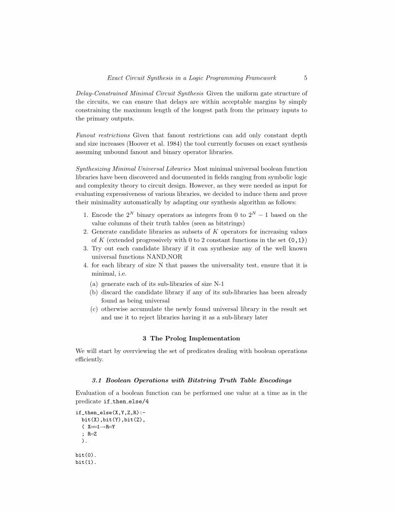
The table 2 lists the complete set of 40 minimal universal libraries induced by oursynthesizer from the 16 binary operators listed in table 1 together with constantfunctions {0,1}.
zero 0 * 1 > 2 head 3< 4 tail 5 ^ 6 + 7nor 8 = 9 ntail 10 <= 11
nhead 12 => 13 nand 14 one 15
Fig. 1: The 16 Operators and their Truth Tables
It is known that minimal universal libraries differ up to (multiplicative) constantfactors with respect to the number of gates needed to express a given circuit. While,in general, minimality is not preserved by rewriting a given minimal representationin terms of a different minimal library, upper bounds (useful in limiting the searchspace) can be generated by using known minimal representations in terms of analternate library.

10 Paul Tarau and Brenda Luderman
nand nor <,1 >,1
=>,0 <=,0 <,=> <,<=
<,= <,nhead <,ntail <,one
>,=> >,<= >,= >,nhead
>,ntail >,one =>,^ =>,nhead
=>,ntail =>,zero <=,^ <=,nhead
<=,ntail <=,zero *,=,0 *,^,1
*,nhead *,ntail +,=,0 +,^,1
+,nhead +,ntail *,=,^ *,=,zero
*,^,one +,=,^ +,=,zero +,^,one
Fig. 2: The 40 Minimal Universal Libraries
4.2 Measuring Expressiveness as Performance on Exact Synthesis
Tasks
The table in Fig. 3 compares a few libraries (with obvious equivalences removed)used in synthesis with respect to the total gates needed to express all the 16 2-argument boolean operations (themselves included). The table in Fig. 4 providesthe same data for a few selected non-minimal universal libraries.
Library Total Library Total Library Total
*,=,0 23 +,^,1 23 <,=> 24*,^,1 25 +,=,0 25 *,=,^ 26+,=,^ 26 <,= 28 =>,^ 28<,1 28 =>,0 28 <,nhead 30
=>,nhead 30 nand 36 nor 36
Fig. 3: Total gates for minimal libraries
Library Total Library Total
<,=>,0,1 20 >,<=,0,1 23*,=,0,1 22 *,^,0,1 24
nand,nor,0,1 24 nand,nor 28nand,0 32 nand,1 32nor,0 32 nor,1 32
Fig. 4: Total gates for some interesting non-minimal libraries
Exact Circuit Synthesis in a Logic Programming Framework 11
This comparison provides our first indicator for the relative expressiveness oflibraries.
By including operations like “⊕” and “=”, that are known to require a relativelyhigh number of other gates (or a high transistor count) to express, one can minimizethe number of operators (and circuit size) required. Using only gates known to havelow transistor-count implementations like nand and nor, the expressiveness dropssignificantly (36 required). Surprisingly, (⇒, 0) and its dual (<, 1) do clearly betterthan nand and nor: they can express all 16 operators with only 28 gates. As section5.2.1 will show, they turn out to also have low transistor count implementations.
Interestingly enough, a library like (∗, =, 0) that provides, arguably, some themost human readable expressions when expressing other operators, has a relativelysmall gate count, 23. The same applies to (∗,⊕, 0) known to provide a boolean ringstructure.
Note also, that besides spotting out the most expressive 1-operator minimal uni-versal libraries (<, 1) and (⇒, 0), the comparison also identifies (<,⇒) as highlyexpressive two operator library (26 gates), with potential for practical design uses,given that < and ⇒ have both low transistor-count implementations (see section5.2.1).
Finally, the overall “winner” of the comparison, expressing the 16 operators withonly 20 gates is the library <,⇒, 0, 1. Given that both of its operators have smalltransistor count implementations (see section 5.2.1) this turns out to be an un-expectedly practical overall winner. Note also that < and ⇒ are dual operators -which makes symbolic reasoning on their properties easier.
4.3 Measuring Expressiveness through Search Space Covering with a
Given Number of Gates
A dual method for evaluating expressiveness is to count the total number of distincttruth tables covered using a given library of gates. One can observe that this canbe easily implemented by reusing the synthesizer’s circuit generator to enumerateand count all possible outputs of circuits of a given size.
Definition 2We call K-gate covering of N-variable functions with library L, the total numberof distinct results obtained by evaluating all single output N-variable circuits con-taining up to K-gates from L.
The tables in figures 5 to 10 show coverings for 2-4 variable functions using 2-5gates, as well as the percentage of the search space covered (22N
distinct values forN variables).
Figures 11 and 12 visualize the coverings for 5-gate functions from various li-braries on 3 and 4 variable truth tables.
Interestingly, one can see that while these results typically parallel those describedin subsection 4.2, an amplifying effect can be observed, especially in the case of thelarger truth tables in Fig. 12. While this time the “winners” are mixed librariescontaining one asymmetrical operator and one in the ⊕, = family, the gap between

12 Paul Tarau and Brenda Luderman
Library Variables Gates Covered % covered
nor 2 2 9 56nand 2 2 9 56nor,0 2 2 10 62nand,1 2 2 10 62<,nhead 2 2 12 75=>,0 2 2 12 75<,1 2 2 12 75
nand,nor 2 2 14 87*,^,1 2 2 12 75<,=> 2 2 14 87=>,^ 2 2 12 75<,= 2 2 12 75
Fig. 5: Coverings for 2-variables, 2 gates
Library Variables Gates Covered % covered
nor 3 4 91 35nand 3 4 91 35nor,0 3 4 91 35nand,1 3 4 91 35<,nhead 3 4 104 40=>,0 3 4 104 40<,1 3 4 104 40
nand,nor 3 4 132 51*,^,1 3 4 170 66<,=> 3 4 204 79=>,^ 3 4 244 95<,= 3 4 244 95
Fig. 6: Coverings for 3-variables, 4 gates
(nand, nor) and (<,⇒) shows that the expressiveness gap is likely to favor circuitsbuilt exclusively or containing asymmetrical operators. This observation is the mainmotivation of the next section that investigates some properties of < and ⇒ basedlibraries, relevant for synthesis tasks.
5 Using Asymmetrical Operators for Combinational Circuit Synthesis
Surprisingly, Half XOR (<) has been neglected by logicians, complexity theoristsand circuit designers, to the point where there are relatively few references to it inthe literature. To some extent, the same is true in the field of circuit design about

Exact Circuit Synthesis in a Logic Programming Framework 13
Library Variables Gates Covered % covered
nor 3 5 139 54nand 3 5 139 54nor,0 3 5 139 54nand,1 3 5 139 54<,nhead 3 5 156 60=>,0 3 5 156 60<,1 3 5 156 60
nand,nor 3 5 211 82*,^,1 3 5 238 92<,=> 3 5 236 92=>,^ 3 5 256 100<,= 3 5 256 100
Fig. 7: Coverings for 3-variables, 5 gates
Library Variables Gates Covered % covered
nor 4 3 143 0nand 4 3 143 0nor,0 4 3 143 0nand,1 4 3 143 0<,nhead 4 3 258 0=>,0 4 3 258 0<,1 4 3 258 0
nand,nor 4 3 366 0*,^,1 4 3 294 0<,=> 4 3 810 1=>,^ 4 3 749 1<,= 4 3 749 1
Fig. 8: Coverings for 4-variables, 3 gates
its dual, (⇒, 0), Logical Implication, which, on the other hand, has been extensivelystudied as an axiomatic basis for both classical and intuitionistic propositional logic.
5.1 Some Minimal Representations with Asymmetric Operators
Figure 13 shows minimal (<, 1)-representations for 0, negation, some 2-input booleanfunctions and the 3-argument IF-THEN-ELSE (ITE), as produced by our synthe-sizer.
Figure 14, shows minimal (⇒, 0)-representations for 1, negation, some 2-inputboolean functions and the 3-argument ITE, as produced by our synthesizer.

14 Paul Tarau and Brenda Luderman
Library Variables Gates Covered % covered
nor 4 4 436 0nand 4 4 436 0nor,0 4 4 436 0nand,1 4 4 436 0<,nhead 4 4 671 1=>,0 4 4 671 1<,1 4 4 671 1
nand,nor 4 4 1142 1*,^,1 4 4 1126 1<,=> 4 4 2286 3=>,^ 4 4 3760 5<,= 4 4 3760 5
Fig. 9: Coverings for 4-variables, 4 gates
Library Variables Gates Covered % covered
nor 4 5 1243 1nand 4 5 1243 1nor,0 4 5 1243 1nand,1 4 5 1243 1<,nhead 4 5 1616 2=>,0 4 5 1616 2<,1 4 5 1616 2
nand,nor 4 5 3394 5*,^,1 4 5 4265 6<,=> 4 5 7166 10=>,^ 4 5 16654 25<,= 4 5 16654 25
Fig. 10: Coverings for 4-variables, 5 gates
As expected, the library (<,⇒, 0, 1) provides more elegant representations, espe-cially for larger circuits (Fig. 15).
Given that (A < 1) is equivalent to (A⇒ 0), the constant 1 can be dropped fromthe library without reducing expressiveness. Note that while the two constantscould be dropped as (<,⇒) forms a minimal universal library, in practice, theiruse provides not only better circuits but also simpler routing constraints as theycan be implemented at 0-cost as connections to VSS and VDD. Moreover, one cankeep in mind that in practice, their occurrences in a synthesized minimal circuitcan always be replaced with a 2-transistor inverter as both A ⇒ 0 and A < 1 are

Exact Circuit Synthesis in a Logic Programming Framework 15
Fig. 11: 5-gate coverings of the 2233-variable functions (more = better)
Fig. 12: 5-gate coverings of the 2244-variable functions (more = better)
equivalent to logical negation. For this reason, our synthesis algorithm will try touse the constant functions, when available, instead of primary input variables.
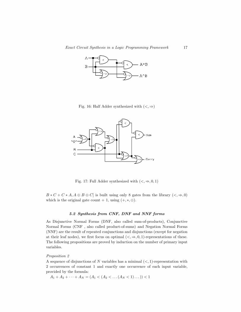
Figure 16 shows a Half Adder synthesized using library (<,⇒) and figure 17shows a Full Adder synthesized with library (<,⇒, 0, 1). As an example of practicalexpressiveness of asymmetric operators, note that the full adder in Fig. 17, [A∗B +

16 Paul Tarau and Brenda Luderman
Function “ < ”Representation
0 1 < 1∼ A A < 1
A ∗B (A < 1) < BA + B (A < (B < 1)) < 1A⇒ B (B < A) < 1A⇐ B (A < B) < 1A⊕B ((A < B) < ((B < A) < 1)) < 1A = B (A < B) < ((B < A) < 1)
A NAND B ((A < 1) < B) < 1A NOR B A < (B < 1)
ITE A B C (A < (C < 1)) < ((B < A) < 1)
Fig. 13: (<, 1)-Representations
Function “⇒ ”Representation
1 0⇒ 0∼ A A⇒ 0
A + B (A⇒ 0)⇒ BA ∗B (A⇒ (B ⇒ 0))⇒ 0A < B (B ⇒ A)⇒ 0A > B (A⇒ B)⇒ 0A = B ((A⇒ B)⇒ ((B ⇒ A)⇒ 0))⇒ 0A⊕B (A⇒ B)⇒ ((B ⇒ A)⇒ 0)
A NOR B ((A⇒ 0)⇒ B)⇒ 0A NAND B A⇒ (B ⇒ 0)ITE A B C (A⇒ (B ⇒ 0))⇒ ((C ⇒ B)⇒ 0)
Fig. 14: (⇒, 0)-Representations
A + B (A⇒ 0)⇒ BA ∗B ((A⇒ 0) < B)A⊕B ((A⇒ B)⇒ (A < B))
A ∗B ∗ C (B ⇒ (A⇒ 0)) < CA + B + C (B < (A⇒ 0))⇒ CITE A B C ((A⇒ (B ⇒ 0))⇒ (B < C)
A ∗B ∗ C ∗D (C ⇒ (B ⇒ (A⇒ 0))) < DA + B + C + D (C < (B < (A⇒ 0)))⇒ D
Fig. 15: (<,⇒, 0, 1)-Representations
Exact Circuit Synthesis in a Logic Programming Framework 17
Fig. 16: Half Adder synthesized with (<,⇒)
Fig. 17: Full Adder synthesized with (<,⇒, 0, 1)
B ∗ C + C ∗ A, A ⊕ B ⊕ C] is built using only 8 gates from the library (<,⇒, 0)which is the original gate count + 1, using (+, ∗,⊕).
5.2 Synthesis from CNF, DNF and NNF forms
As Disjunctive Normal Forms (DNF, also called sum-of-products), ConjunctiveNormal Forms (CNF , also called product-of-sums) and Negation Normal Forms(NNF) are the result of repeated conjunctions and disjunctions (except for negationat their leaf nodes), we first focus on optimal (<,⇒, 0, 1)-representations of these.The following propositions are proved by induction on the number of primary inputvariables.
Proposition 2A sequence of disjunctions of N variables has a minimal (<, 1)-representation with2 occurrences of constant 1 and exactly one occurrence of each input variable,provided by the formula:
A1 + A2 + · · ·+ AN = (A1 < (A2 < . . . (AN < 1) . . . )) < 1

18 Paul Tarau and Brenda Luderman
Proposition 3A sequence of conjunctions of N variables has a minimal (<, 1)-representation withN − 1 occurrences of constant 1 and exactly one occurrence of each input variable,provided by the formula:
A1 ∗A2 ∗ . . . AN−1 ∗AN = ((A1 < 1) < ((A2 < 1) < . . . ((AN−1 < 1) < AN ) . . . )
An optimal (⇒, 0)-representation of conjunctions and disjunctions is provided asfollows.
Proposition 4A sequence of conjunctions of N variables has a minimal (⇒, 0)-representationwith 2 occurrences of constant 0 and exactly one occurrence of each input variable,provided by the formula:
A1 ∗A2 ∗ · · · ∗AN = (A1 ⇒ (A2 ⇒ . . . (AN ⇒ 0) . . . ))⇒ 0
Proposition 5A sequence of disjunctions of N variables has a minimal (⇒, 0)-representation withN − 1 occurrences of constant 0 and exactly one occurrence of each input variable,provided by the formula:
A1 + A2 + . . . AN−1 + AN = ((A1 ⇒ 0) ⇒ ((A2 ⇒ 0) ⇒ . . . ((AN−1 ⇒ 0) ⇒AN ) . . . )
Synthesis from CNF and DNF formulae (that can be obtained directly from truthtable descriptions of circuits) proceeds by applying the encodings provided by theprevious propositions recursively, followed by (and interleaved with) simplificationsteps.
Negation normal forms (NNF) representations can benefit from combining thesmaller (N+1 gates) representations for conjunctions using ⇒ with the smaller(N+1 gates) representation for disjunctions using <. This property provides anintuitive explanation for the expressiveness of libraries based on (<,⇒).
Note that to avoid the large delays induced by the linear chains of operators, bal-anced trees can be used instead without changing the number of gates significantly.
Proposition 6A formula in NNF form is convertible to a (<,⇒) equivalent of the same size up toa constant factor. Balancing a (<,⇒)-formula yields and equivalent NNF-formulaof the same size up to a constant factor.
The proposition follows from the fact (Props. 2, 4) that disjunctions and conjunc-tions can be rewritten with (<,⇒)-expressions that do not duplicate variable oc-currences.
5.2.1 Transistor Implementations for (<,⇒)-circuits
Clearly as A < B is equivalent to nor(A,∼ B), an obvious 6-transistor implemen-tation is obtained when input B drives a 2-transistor inverter while its output andinput A drive a 4-transistor NOR gate.

Exact Circuit Synthesis in a Logic Programming Framework 19
This logic circuit is shown in Fig. 18. The output node, A < B, has a direct pathto the power nodes VDD and VSS through the source connections of the transistorsconnected to it. As a result, the output is called “buffered” and the logic circuittype is “powered”.
Fig. 18: Powered 6-Transistor A < B
Fig. 19: Semi-Powered 4-Trans. A < B
To reduce transistor count, a pass transistor logic (PTL) circuit for A < B canbe implemented using 4 transistors. In this circuit, the output node, A < B, in Fig.19 has a direct path to the power net VSS while input B provides the VDD power.
20 Paul Tarau and Brenda Luderman
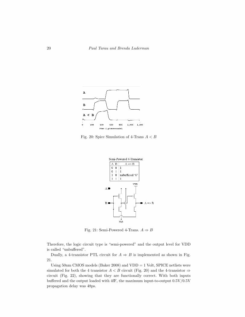
Fig. 20: Spice Simulation of 4-Trans A < B
Fig. 21: Semi-Powered 4-Trans. A⇒ B
Therefore, the logic circuit type is “semi-powered” and the output level for VDDis called “unbuffered”.
Dually, a 4-transistor PTL circuit for A ⇒ B is implemented as shown in Fig.21.
Using 50nm CMOS models (Baker 2008) and VDD = 1 Volt, SPICE netlists weresimulated for both the 4 transistor A < B circuit (Fig. 20) and the 4-transistor ⇒circuit (Fig. 22), showing that they are functionally correct. With both inputsbuffered and the output loaded with 4fF, the maximum input-to-output 0.5V/0.5Vpropagation delay was 48ps.

Exact Circuit Synthesis in a Logic Programming Framework 21
Fig. 22: Spice Simulation of 4-Trans A⇒ B
The constant function 1 can be implemented by direct routing to the VDD powergrid. Similarly, the constant function 0 can be implemented by direct routing to theVSS power grid. Buffering of the unbuffered signals can be handled by adding tothe synthesis algorithm an additional constraint to force alternation of the < and⇒ gates.In conclusion, assuming a design using PTL-logic, the transistor count for an im-plementation of the < and ⇒ functions is 4, while constant functions 1 and 0 areessentially free, with transistor count 0.
6 Conclusion and Future Work
We have described a general logic programming based exact circuit synthesis al-gorithm and shown how Prolog language features like logic variables and back-tracking can be used to provide efficient, a concise and elegant implementations.Two quantitative methods have been provided for measuring the relative expres-siveness of boolean function libraries using exact synthesis. Both indicators suggestthat libraries based on asymmetrical operators (<,⇒) are a practical alternative toNAND and NOR-based libraries. Their relative expressiveness challenges, to someextent, the widely believed statement (Dietmeyer 1971; Canteaut and Videau 2005)that symmetric functions are genuinely more interesting for circuit synthesis. Whilewe have provided low cost transistor models for < and ⇒ gates and tested theirsignal correctness with SPICE, the validation of their use in various context re-quires more extensive SPICE simulations as well as precise area, delay and powerestimates.
On the general synthesis algorithm side, we plan to add tabling of sub-circuitsto avoid recomputation. It has been pointed out in recent papers like (Große et al.2007; Drechsler ) that SAT-solver and circuit synthesis algorithms are synergis-

22 Paul Tarau and Brenda Luderman
tically related. Adapting intelligent backtracking mechanisms like those used inmodern SAT-solvers will be implemented to improve performance. Using proper-ties like NPN-equivalence (Young and Muroga 1985; Muroga and Lai 1976; Meyerand Kocan 2007) will provide library specific constraints likely to speed up search.
As (⇒, 0) has been used as a foundation of various implicative formalizations ofclassic and intuitionistic logics, we plan to use the powerful rewriting mechanismsavailable for it (that can be transposed to (<, 1) using duality) to extend exactsynthesis with symbolic rewriting based heuristics.
Given that A < B and A ⇒ B are order relations, suggests their use in novelanalog or non-silicon designs, provided that one can measure that signal A is in agiven sense weaker than B.
Polymorphic or multi-functional (Sekanina et al. 2006) NAND/NOR gates havebeen recently synthesized at transistor level (Sekanina 2005; Stoica et al. 2006).Given the significantly higher expressiveness of the library (<,⇒) we plan to tryout a similar experiment using it.
Given that exact synthesis of reversible circuits using Fredkin and Toffoli gates(Maslov et al. 2005; Maslov et al. 2007; Große et al. 2007) is important for fu-ture quantum computing and adiabatic computing research, we plan to extend thesynthesizer to support such libraries optimally.
References
Baker, R. J. 2008. CMOS Circuit Design, Layout and Simulation. John Wiley and Sons,Hoboken, NJ, USA.
Bryant, R. E. 1986. Graph-based algorithms for boolean function manipulation. IEEETransactions on Computers 35, 8, 677–691.
Canteaut, A. and Videau, M. 2005. Symmetric Boolean Functions. IEEE Transactionson Information Theory 51, 8, 2791–2811.
Clocksin, W. and Mellish, C. 1987. Programming in Prolog. Springer-Verlag. 3rdedition.
Culliney, J. N., Young, M. H., Nakagawa, T., and Muroga, S. 1979. Results ofthe Synthesis of Optimal Networks of AND and OR Gates for Four-Variable SwitchingFunctions. IEEE Trans. Computers 28, 1, 76–85.
Davies, D. W. 1957. Switching functions of three variables. Trans. Inst. Radio Engi-neers 6, 4, 265–275.
Dietmeyer, D. L. 1971. Logic Design of Digital Systems. Allyn and Bacon.
Drechsler, R. Using Synthesis Techniques in SAT Solvers. cite-seer.ist.psu.edu/drechsler04using.html.
Drechsler, R. and Gunther, W. 1998. Exact Circuit Synthesis. In InternationalWorkshop on Logic Synthesis.
Fruhwirth, T. Theory and practice of constraint handling rules. J. LOGIC PROGRAM-MING 1994:19,20.
Große, D., Chen, X., Dueck, G. W., and Drechsler, R. 2007. Exact sat-basedtoffoli network synthesis. In ACM Great Lakes Symposium on VLSI, H. Zhou, E. Macii,Z. Yan, and Y. Massoud, Eds. ACM, 96–101.
Hoover, H. J., Klawe, M. M., and Pippenger, N. 1984. Bounding Fan-out in LogicalNetworks. J. ACM 31, 1, 13–18.
Exact Circuit Synthesis in a Logic Programming Framework 23
Knuth, D. 2006. The Art of Computer Programming, Volume 4, draft. http://www-cs-faculty.stanford.edu/∼knuth/taocp.html.
Lai, H. C. and Muroga, S. 1987. Logic Networks with a Minimum Number ofNOR(NAND) Gates for Parity Functions of Variables. IEEE Trans. Computers 36, 2,157–166.
Maslov, D., Dueck, G. W., and Miller, D. M. 2005. Synthesis of Fredkin-Toffolireversible networks. IEEE Trans. VLSI Syst. 13, 6, 765–769.
Maslov, D., Dueck, G. W., and Miller, D. M. 2007. Techniques for the synthesis ofreversible Toffoli networks. ACM Trans. Design Autom. Electr. Syst. 12, 4.
Meyer, J. and Kocan, F. 2007. Sharing of SRAM Tables Among NPN-Equivalent LUTsin SRAM-Based FPGAs. IEEE Trans. VLSI Syst. 15, 2, 182–195.
Mira, J. and Alvarez, J. R., Eds. 2005. Artificial Intelligence and Knowledge Engineer-ing Applications: A Bioinspired Approach: First International Work-Conference on theInterplay Between Natural and Artificial Computation, IWINAC 2005, Las Palmas, Ca-nary Islands, Spain, June 15-18, 2005, Proceedings, Part II. Lecture Notes in ComputerScience, vol. 3562. Springer.
Mishchenko, A. and Brayton, R. 2002. A boolean paradigm for multivalued logicsynthesis. In Proc. IgVLS’02, June, 2002, pp. 173-177.
Mishchenko, A. and Sasao, T. 2002. Encoding of Boolean functions and its applicationto LUT cascade synthesis. In International Workshop on Logic Synthesis.
Muroga, S. and Lai, H. C. 1976. Minimization of Logic Networks Under a GeneralizedCost Function. IEEE Trans. Computers 25, 9, 893–907.
O’Donnell, J. Hardware description with recursion equations. In Proceedings of theIFIP 8th International Symposium on Computer Hardware Description Languages andtheir Applications, pages 363–382. NorthHolland, April 1987.
Oettinger, A. G. and Aiken, H. H. 1962. Retiring computer pioneer. Commun.ACM 5, 6, 298–299.
Reintjes, P. 1992. Elegant technologies. published electronically athttp://z.zhurnal.net/ElegantTechnologies.pdf.
Riedel, M. 2004. Cyclic Combinational Circuits. In Ph.D. Dissertation, Caltech.
Sekanina, L. 2005. Evolutionary design of gate-level polymorphic digital circuits. InEvoWorkshops, F. Rothlauf, J. Branke, S. Cagnoni, D. W. Corne, R. Drechsler, Y. Jin,P. Machado, E. Marchiori, J. Romero, G. D. Smith, and G. Squillero, Eds. LectureNotes in Computer Science, vol. 3449. Springer, 185–194.
Sekanina, L. 2006. Evolutionary design of digital circuits: Where are current limits? SeeStoica et al. (2006), 171–178.
Sekanina, L., Starecek, L., Gajda, Z., and Kotasek, Z. 2006. Evolution of multi-functional combinational modules controlled by the power supply voltage. See Stoicaet al. (2006), 186–193.
Shannon, C. E. 1993. Claude Elwood Shannon: collected papers. IEEE Press, Piscataway,NJ, USA.
Shende, V., Prasad, A., Markov, I., and Hayes, J. 2003. Synthesis of reversible logiccircuits. In IEEE Trans. on CAD 22, pp. 710–722.
Stoica, A., Arslan, T., Suess, M., Yalcin, S., Keymeulen, D., Higuchi, T., Ze-bulum, R. S., and Aydin, N., Eds. 2006. First NASA/ESA Conference on AdaptiveHardware and Systems (AHS 2006), 15-18 June 2006, Istanbul, Turkey. IEEE ComputerSociety.
Stoica, A., Zebulum, R. S., Keymeulen, D., and Daud, T. 2005. Transistor-levelcircuit experiments using evolvable hardware. See Mira and Alvarez (2005), 366–375.

24 Paul Tarau and Brenda Luderman
Stoica, A., Zebulum, R. S., Keymeulen, D., Ramesham, R., Neff, J., andKatkoori, S. 2006. Temperature-adaptive circuits on reconfigurable analog arrays.See Stoica et al. (2006), 28–31.
Tarau, P. and Luderman, B. 2007. A Logic Programming Framework for CombinationalCircuit Synthesis. In 23rd International Conference on Logic Programming (ICLP),LNCS 4670. Springer, Porto, Portugal, 180–194.
Tarau, P. and Luderman, B. 2008a. Exact combinational logic synthesis and non-standard circuit design. In CF ’08: Proceedings of the 2008 conference on Computingfrontiers. ACM, New York, NY, USA, 179–188.
Tarau, P. and Luderman, B. 2008b. Revisiting Exact Combinational Circuit Synthesis.In Proceedings of the 2008 ACM symposium on Applied computing. Fortalezza, Brazil,1758–1759.
Young, M. H. and Muroga, S. 1985. Symmetric Minimal Covering Problem and Min-imal PLA’s with Symmetric Variables. IEEE Trans. Computers 34, 6, 523–541.
Exact Circuit Synthesis in a Logic Programming Framework 25
APPENDIX
syn(E):-syn([<, =>],[0,1],E).
syn(Fs,E):-syn(Fs,[],E).
syn(Fs,Cs,E):-expr2tt(E,NV:TT),syn(Fs,Cs,NV,TT).
syn(Fs,Cs,NV,TT):-
init_tts(NV,TT, MG,TTs),
showsyn(NV,MG,Fs,Cs,TTs).
showsyn(NV,MG,Fs,Cs,TTs):-
portray_clause(syn(NV,MG,Fs,Cs,TTs)),
show_tts(NV,TTs),
statistics(runtime,[T1,_]),
synthesize(NV,MG,Fs,Cs,TTs, Xs,Gs,Ys),
R=(Xs:Gs=Ys:TTs),!,
statistics(runtime,[T2,_]),
portray_clause(R),
T is T2-T1,
write(time_ms=T),nl,fail. % to avoid unnecessary bindings to be shown
synexp(E,MG,Fs,Cs, NV:TTs, Xs,Gs,Ys):-
expr2tt(E,NV:TTs),
synthesize(NV,MG,Fs,Cs, TTs, Xs,Gs,Ys).
% enumerates circuits in increasing order
enumerateCircuits(_MG,_M,_Fs,Is, Is,[TT]):-
% when outputs connect directly to inputs
member(TT,Is).
enumerateCircuits(MG,M,Fs,Is, Gs,Os):-
% when gates connect inputs to outputs
generate_gates(MG,M,Fs,[_AnyTT],Is, Gs,Os,_).
%-- bitstring int operations on boolean functions
% can also be seen as f:[0..M]x[0..M]→[0..M]
% or f:[0..3]→[0..1] or f←[0..15] using their tt
applyF(’~’,M,A,R):-R is xor(M,A).
applyF(’nand’,M,X1,X2,X3):-X3 is xor(M,/\(X1,X2)).
applyF(’nor’,M,X1,X2,X3):-X3 is xor(M,\/(X1,X2)).
applyF(’<’,_,X1,X2,X3):-X3 is xor(X1,\/(X1,X2)). %k
applyF(’>’,_,X1,X2,X3):-X3 is xor(X1,/\(X1,X2)). %k
applyF(’=>’,M,X1,X2,X3):-X3 is \/(xor(M,X1),X2).
applyF(’<=’,M,X1,X2,X3):-X3 is \/(X1,xor(M,X2)).
applyF(’∗’,_,X1,X2,X3):-X3 is /\(X1,X2). %k

26 Paul Tarau and Brenda Luderman
applyF(’+’,_,X1,X2,X3):-X3 is \/(X1,X2). %k
applyF(’=’,M,X1,X2,X3):-X3 is xor(M,xor(X1,X2)).
applyF(’^’,_,X1,X2,X3):-X3 is xor(X1,X2). %k
applyF(’head’,_,X1,_,X3):-X3 is X1.
applyF(’tail’,_,_,X2,X3):-X3 is X2.
applyF(’nhead’,M,X1,_,X3):-X3 is xor(M,X1).
applyF(’ntail’,M,_,X2,X3):-X3 is xor(M,X2).
applyF(’zero’,_,_,_,0).
applyF(’one’,M,_,_,M).
applyF(’ite’,_M,A,B,C,R):-D is xor(B,C),E is /\(D,A),R is xor(E,C).
% --------- pre-synthesis initializer ----------------------
% input initializer/generator
% precomputes bitvector representations of variables and constants
initInputs(NV,Cs, Mask,Vs,Is):-
init_vars(NV,Mask,Vs),
init_consts(Cs,Mask,ICs),
append(ICs,Vs,Is).
% constant mapping
const(0,_M,0). % false=0const(1,M,M). % true=M (Mask)
% precompute constants
init_consts([],_,[]).
init_consts([C |Cs],M,[VC |ICs]):-const(C,M,VC),
init_consts(Cs,M,ICs).
% precomputes bitvector values for variables
init_vars(NV,Mask,VPairs):-
all_ones_mask(NV,Mask),
vars_to_bitstring_ints(NV,VPairs).
% ---------- pre-synthesis converters ---------
% converts expressions and truth table notations
% to canonical truth table form
expr2tt(NV:TT,NV:TTs):-integer(NV),!,to_list(TT,TTs).
expr2tt((Vs:E),NV:TT):-!,to_list(E,Es),eval_expr(Vs,Es,NV,TT).
expr2tt(E,NV:TT):-
Vs=[],eval_expr(Vs,E,NV,TT).
% expression evaluator - supports all 16 binary ops, ~,ite
eval_expr(Vs0,E,NV,I):-
to_list(E,Es0),
copy_term(Vs0+Es0,Vs+Es),numbervars(Vs+Es,0,NV),all_ones_mask(NV,M),
mapeval(Es,NV,M,R),

Exact Circuit Synthesis in a Logic Programming Framework 27
!,
R=I.
% evaluates a list of expressions
mapeval([],_,_,[]).
mapeval([E |Es],NV,M,[R |Rs]):-eval_one(E,NV,M,R),
mapeval(Es,NV,M,Rs).
% evaluates one expression
eval_one(E,_,M,I):-integer(E),!,
const(E,M,I).
eval_one(’$VAR’(K),NV,_M,I):-!,
var_to_bitstring_int(NV,K,I).
eval_one(E,NV,M,I):-functor(E,F,2),!,
arg(1,E,X),arg(2,E,Y),
eval_one(X,NV,M,A),eval_one(Y,NV,M,B),
applyF(F,M,A,B,I).
eval_one(~(E),NV,M,I):-!,
eval_one(E,NV,M,A),
I is xor(M,A).
eval_one(ite(X,Y,Z),NV,M,I):-!,
eval_one(((X∗Y)+(~(X)∗Z)),NV,M,I).eval_one(mux(X,Y,Z),NV,M,I):-!,
eval_one(((~(X)∗Y)+(X∗Z)),NV,M,I).
% ------- post-synthesis converters -----
% canonical form converter - for more readable gates
symplify_dag(NV,Cs,VVs,Gs, Vs,Os,Ys,NewGs):-
simplify_consts(NV,Cs,D),
simplify_list(VVs,Vs,D),
simplify_list(Os,Ys,D),
reverse(Gs,Rs),
simplify_gates(Rs,NewGs,D).
simplify_consts(NV,Cs,D):-
all_ones_mask(NV,M),
init_consts(Cs,M,As),
simplify_list(As,Cs,D).
simplify_list([],[],_).
simplify_list([C |Cs],[X |Xs],D):-to_var(C,X,D),simplify_list(Cs,Xs,D).
simplify_gates([],[],_).
simplify_gates([G |Gs],[T |Ts],D):-G=..[g,Op |As],!,
simplify_list(As,Xs,D),
T=..[Op |Xs],simplify_gates(Gs,Ts,D).
simplify_gates([_C |Gs],Ts,D):-simplify_gates(Gs,Ts,D).
28 Paul Tarau and Brenda Luderman
to_var(C,X,D):-member(v(X,C),D),!.
% ---- post-synthesis result formatters
% prints the truth table(s) associated
% to a (list) of formulae or integer tts
tts(EorEs):-
expr2tt(EorEs,NV:TTs),
show_tts(NV,TTs).
% prints out a list of NV variable truth tables TTs
show_tts(NV,TTs):-
( member(TT,TTs),
show_tt(NV,TT),
fail
; true
).
% prints out a truth table
show_tt(NV,Int):-
show_tt(NV,Int,BsV),
write(BsV),nl,
fail
; nl.
show_tt(NV,Int,Bs:V):-
findall(Bs,tt_line(NV,Bs),Bss),
T=..[tt |Bss],functor(T,_,N),
between(1,N,I),
arg(I,T,Bs),
I1 is N-I,
getbit(Int,I1,V).
% prints out a line in a truth table
tt_line(0,[]).
tt_line(N,[B |Bs]):-N>0,N1 is N-1,(B=0;B=1),tt_line(N1,Bs).
% gets a the state of Bit position in Int, returned as Val in {0,1}
getbit(Int,Bit,Val):- Val is (/\(Int,(1<<Bit)))>>Bit.
% default truth table initialization
init_tts(NV,TT, MG,TTs):-
to_list(TT,TTs),
length(TTs,L),
MG0 is L∗NV∗(1<<NV),(MG0<6→MG=6;MG=MG0),write([’TTs’=TTs,’MG’=MG]),nl.
% ensures non-list arguments are lifted to lists
to_list(Es,R):-nonvar(Es),Es=[_ |_],!,R=Es.to_list(Es,R):-nonvar(Es),Es=[],!,R=[].to_list(E,[E]).
Exact Circuit Synthesis in a Logic Programming Framework 29
% arity 1 gate - negation
newGateByArity(F,M,Os,g(F,VK,VO),VO):-F=’~’,!,member(VK,Os),
applyF(F,M,VK,VO).
% arity 3 gate - if-then-else
newGateByArity(F,M,Os,g(F,VK,VI,VJ,VO),VO):-F=ite,!,member(VK,Os),
member(VI,Os),
member(VJ,Os),
applyF(F,M,VK,VI,VJ,VO).
% 16 arity 2 gates
newGateByArity(F,M,Os,g(F,VI,VJ,VO),VO):-
member(VI,Os),
member(VJ,Os),
applyF(F,M,VI,VJ,VO).
% trims truth table lists of plain inputs - they need no search
trim_tts(TTs,Is,SolvedTTs,UnSolvedTTs):-
findall(X,(member(X,TTs),member(X,Is)),SolvedTTs),
findall(X,(member(X,TTs),\+member(X,Is)),UnSolvedTTs).
%check_progress(VO,Os,_OldTTs,_NewTTs):-member(VO,Os),!,fail.
check_progress(VO,OldTTs,NewTTs):-pick(VO,OldTTs,More),!,NewTTs=More.check_progress(_VO,TTs,TTs).
% selects/inserts a value from/to a list
pick(X,[X |Xs],Xs).pick(X,[Y |Xs],[Y |Ys]):-pick(X,Xs,Ys).