Embed Size (px)
Citation preview
Dear Customers and Aviation Safety colleagues,
Despite the worldwide economic environment, theincreased operator participation in the last AirbusFlight Safety Conference (last October 08) is a positiveillustration that our Safety Community remainedfocussed on our mutual objectives. You were indeed20% more operators compared to the previousconference.
The articles included in this issue 7 of Safety Firstunderline once more that aviation safety is a globalissue that requires the 4 key elements: designenhancement, maintenance & operational procedures,training, and compliance to Standard OperatingProcedures (both in operational and maintenancefields).
The World witnessed the USA1549 Hudson riverditching, illustrating the essential role of safetypreparedness, even for extremely rare events. Thisserves as an excellent reminder to all of us that goodairmanship and crew resource management willalways remain essential for a positive outcome.
To the cockpit and cabin crew of USA1549: “Well done!”
Yannick MALINGE
Vice President Flight Safety
Yannick MALINGE
Vice President Flight Safety
Editorial # 07 February 2009
ContentThe Airbus Safety Magazine . . . . . . . . . . . . . . . . . 2Information . . . . . . . . . . . . . . . . . . . . . . . . . . . . . . . . . . . . . . . . . . . 3Airbus AP/FD TCAS mode: a new steptowards safety improvementPaule Botargues . . . . . . . . . . . . . . . . . . . . . . . . . . . . . . . . . . . . 4Braking system cross connections Thierry Thoreau . . . . . . . . . . . . . . . . . . . . . . . . . . . . . . . . . . . . . . 10Upset Recovery Training Aid, Revision 2Larry Rockliff . . . . . . . . . . . . . . . . . . . . . . . . . . . . . . . . . . . . . . . . . 16Fuel pumps left in OFF positionFrédéric Combes . . . . . . . . . . . . . . . . . . . . . . . . . . . . . . . . . . . 20Avoiding dual bleed lossPatrick Grave, Christophe Mathe . . . . . . . . . . . . . 26
Safety First# 07 February 2009
Safety First is published by Airbus S.A.S1, rond point Maurice Bellonte31707 Blagnac Cedex / France
Editor:Yannick Malinge, Vice President Flight Safety
Concept Design byMULTI MEDIA SUPPORT 20090053
Computer Graphic by Quat’coul
Copyright: GSE 420 0046/09
Photos copyright Airbus Photos by ExM: Hervé Berenger, PhilippeMasclet, Hervé Goussé.Photo copyright Germanwings
Computer rendering by ABAC
Printed in France by AMADIO
© Airbus S.A.S. 2009 – All rights reserved. Confidential and proprietary documents.
By taking delivery of this Brochure (hereafter “Brochure”), you accept on behalf of your company to comply with the following guidelines:
> No other intellectual property rights are granted by the delivery of this Brochure than theright to read it, for the sole purpose of information.
> This Brochure and its content shall not be modified and its illustrations and photos shallnot be reproduced without prior written consent of Airbus.
> This Brochure and the materials it contains shall not, in whole or in part, be sold, rented, or licensed to any third party subject to payment.
This Brochure contains sensitive information that is correct at the time of going to press. This information involves a number of factors that could change over time, effecting thetrue public representation. Airbus assumes no obligation to update any information containedin this document or with respect to the information described herein.
Airbus SAS shall assume no liability for any damage in connection with the use of thisBrochure and of the materials it contains, even if Airbus SAS has been advised of the likelihood of such damages.
Safety FirstThe Airbus Safety MagazineFor the enhancement of safe flight through increased knowledge and communications.
Safety First is published by the Flight Safety Departmentof Airbus. It is a source of specialist safety informationfor the restricted use of flight and ground crew memberswho fly and maintain Airbus aircraft. It is also distributedto other selected organisations.
Material for publication is obtained from multiple sourcesand includes selected information from the Airbus FlightSafety Confidential Reporting System, incident andaccident investigation reports, system tests and flighttests. Material is also obtained from sources within theairline industry, studies and reports from governmentagencies and other aviation sources.
All articles in Safety First are presented for informationonly and are not intended to replace ICAO guidelines,standards or recommended practices, operator-
mandated requirements or technical orders. The contentsdo not supersede any requirements mandated by the Stateof Registry of the Operator’s aircraft or supersede or amendany Airbus type-specific AFM, AMM, FCOM, MELdocumentation or any other approved documentation.
Articles may be reprinted without permission, except wherecopyright source is indicated, but with acknowledgementto Airbus. Where Airbus is not the author, the contents ofthe article do not necessarily reflect the views of Airbus,neither do they indicate Company policy.
Contributions, comment and feedback are welcome. Fortechnical reasons the editors may be required to make editorialchanges to manuscripts, however every effort will be madeto preserve the intended meaning of the original. Enquiriesrelated to this publication should be addressed to:
AirbusFlight Safety Department (GSE)1, rond point Maurice Bellonte31707 Blagnac Cedex - FranceContact: Marie-Josée EscoubasE-mail: [email protected]: +33 (0)5 61 93 44 29
20090053_Safety First Magazine-7 - V-eRN.qxp:20080635 12/02/09 14:35 Page 2
3Safety FirstThe Airbus Safety Magazine
# 07 February 2009
Information
Magazine distribution
If you wish to subscribe to Safety First, please fillout the subscription form that you will find at theend of this issue.Please note that the paper copies will only beforwarded to professional addresses.
Your articlesThis magazine is a tool to help share information,we therefore rely on your inputs. We are still lookingfor articles from operators that we can help passon to other operators through the magazine.If you have any inputs then please contact us.
Contact: Marie-Josée [email protected]: +33 (0) 5 61 93 44 29
Safety Information on the Airbus websitesOn the different Airbus websites we are buildingup more and more safety relevant information foryou to use.
The present and previous issues of Safety Firstcan be accessed to in the Flight OperationsCommunity, Safety and Operational Materialschapter, at https://w3.airbusworld.com
If you do not yet have access rights, pleasecontact your IT administrator.
Other safety and operational expertisepublications, like the Flight Operation BriefingNotes (FOBN), Getting to Grips with …brochures,e-briefings etc… are regularly released as well inthe Flight Operations Community at the abovesites.
Flight Safety Hotline:
+33 (0)6 29 80 86 66E-mail:[email protected]
4
Airbus AP/FDTCAS mode:a new step towards safety Improvement
By: Paule BOTARGUESEngineer, Automatic Flight Systems, Engineering
1 Introduction
The Traffic Collision Avoidance System (TCAS) hasbeen introduced to reduce the risks associatedwith mid-air collision threats. Today this safety goalhas globally been reached.
However, surprise and stress created by TCASResolution Advisories may lead to non-optimumcrew response, resulting in a lack of propercommunication with ATC, undue aircraft altitudedeviations, injuries in the cabin and the jeopardizingof the aircraft’s safety.This article will review the current TCAS interfaceand procedures. It will then present the Auto Pilot/Flight Director (AP/FD) TCAS mode functiondeveloped by Airbus, and its numerous operationalbenefits, which further enhance the pilot interfaces.
2 Current TCASinterface and procedures
Traffic Advisory (TA)When the TCAS considers an intruder to be apotential threat, it generates a TA. This advisory aims at alerting crews to the intruder’sposition. TAs are indicated to the crew by:• An aural message, “Traffic, Traffic” • Specific amber cues on the Navigation Display,
which highlight the intruder’s position.
No specific action is expected from the crewfollowing a TA.
12
15
18
09
06
0300
33
3027
22
24
5
10
+70
VOR1 ADF2
GS 260 TAS 250
260 / 12
+06
Figure 1: Navigation Display in case of TCAS TA
Red area indicatingthe forbidden verticalspeed domain
"Adjust V/S, Adjust"
5Safety FirstThe Airbus Safety Magazine
# 07
• Green / red zones on the Vertical Speed Indicator(VSI) specifying the type of maneuver the pilothas to perform.
In order to fly the required maneuver, the pilotselects both the Auto Pilot (AP) and Flight Directors(FD) to OFF, and adjusts the pitch attitude of theaircraft as required, so as to reach the properVertical Speed (V/S). This unfamiliar flying techniqueincreases the stress level already induced by thetriggering of the Resolution Advisory.
Resolution Advisory (RA)If the TCAS considers an intruder to be a realcollision threat, it generates an RA.In most cases, the TCAS will trigger a TrafficAdvisory before a Resolution Advisory. RAs are indicated to the pilots by:• An aural message specifying the type of vertical
order (Climb, Descent, Monitor, Adjust…) • Specific red cues on the Navigation Display
materializing the intruder
February 2009
Figure 2: TCAS RA HMI without AP/FD TCAS mode
6
3 AP/FD TCAS mode concept
Airbus has carried out an in-depth analysis of:• Needs expressed by airline pilots• Human factor studies linked to the TCAS system• Recommendations given by airworthiness
authorities.
This resulted in the development of a newconcept called AP/FD TCAS guidance, via theAuto Flight System (AFS), to support pilotsflying TCAS RAs.
The AP/FD TCAS mode is a vertical guidancemode built into the Auto Flight computer. It controlsthe vertical speed (V/S) of the aircraft on a verticalspeed target adapted to each RA, which isacquired from TCAS. With the Auto Pilot engaged, it allows the pilot tofly the TCAS RA maneuvre automatically.With the Auto Pilot disengaged, the pilot can flythe TCAS RA maneuvre manually, by following theTCAS Flight Director pitch bar guidance. It has to be considered as an add-on to theexisting TCAS features (traffic on NavigationDisplay, aural alerts, vertical speed green / redzones materializing the RA on the Vertical SpeedIndicator).
In case of a TCAS RA, the AP/FD TCAS modeautomatically triggers the following:• If both AP and FDs are engaged, the AP/FD
vertical mode reverts to TCAS mode, whichprovides the necessary guidance for the AutoPilot to automatically fly the TCAS maneuver
• If the AP is disengaged and FDs are engaged,the TCAS mode automatically engages as thenew FD guidance. The FD pitch bar provides anunambiguous order to the pilot, who simply hasto centre the pitch bar, to bring the V/S of theaircraft on the V/S target (green zone)
• If both AP and FDs are OFF, the FD bars willautomatically reappear with TCAS mode guidingas above.
Note: At any time, the crew keeps the possibilityto disconnect the AP and the FDs, and is capable to respond manuallyto a TCAS RA by flying according to the“conventional” TCAS procedure (i.e. flyingthe vertical speed out of the red band).
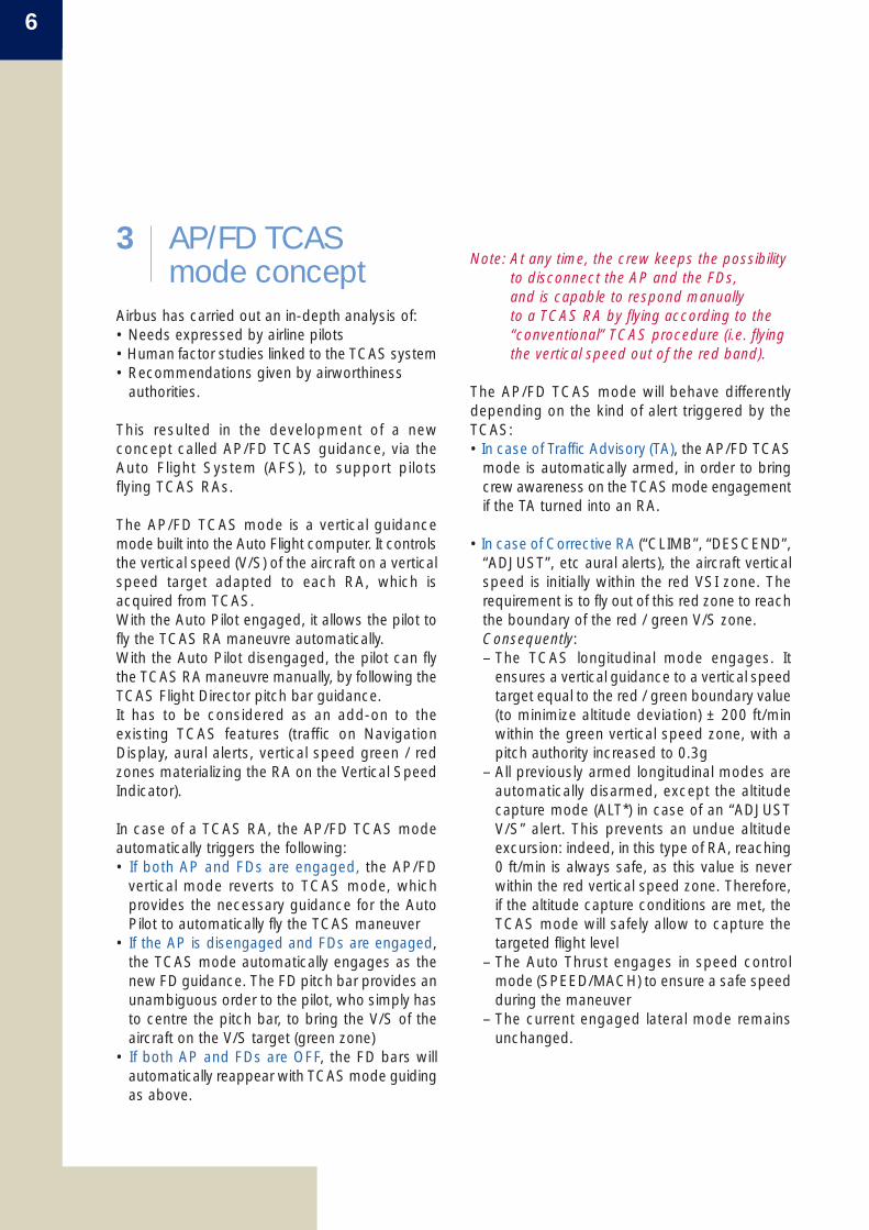
The AP/FD TCAS mode will behave differentlydepending on the kind of alert triggered by theTCAS:• In case of Traffic Advisory (TA), the AP/FD TCAS
mode is automatically armed, in order to bringcrew awareness on the TCAS mode engagementif the TA turned into an RA.
• In case of Corrective RA (“CLIMB”, “DESCEND”,“ADJUST”, etc aural alerts), the aircraft verticalspeed is initially within the red VSI zone. Therequirement is to fly out of this red zone to reachthe boundary of the red / green V/S zone. Consequently:– The TCAS longitudinal mode engages. It
ensures a vertical guidance to a vertical speedtarget equal to the red / green boundary value(to minimize altitude deviation) ± 200 ft/minwithin the green vertical speed zone, with apitch authority increased to 0.3g
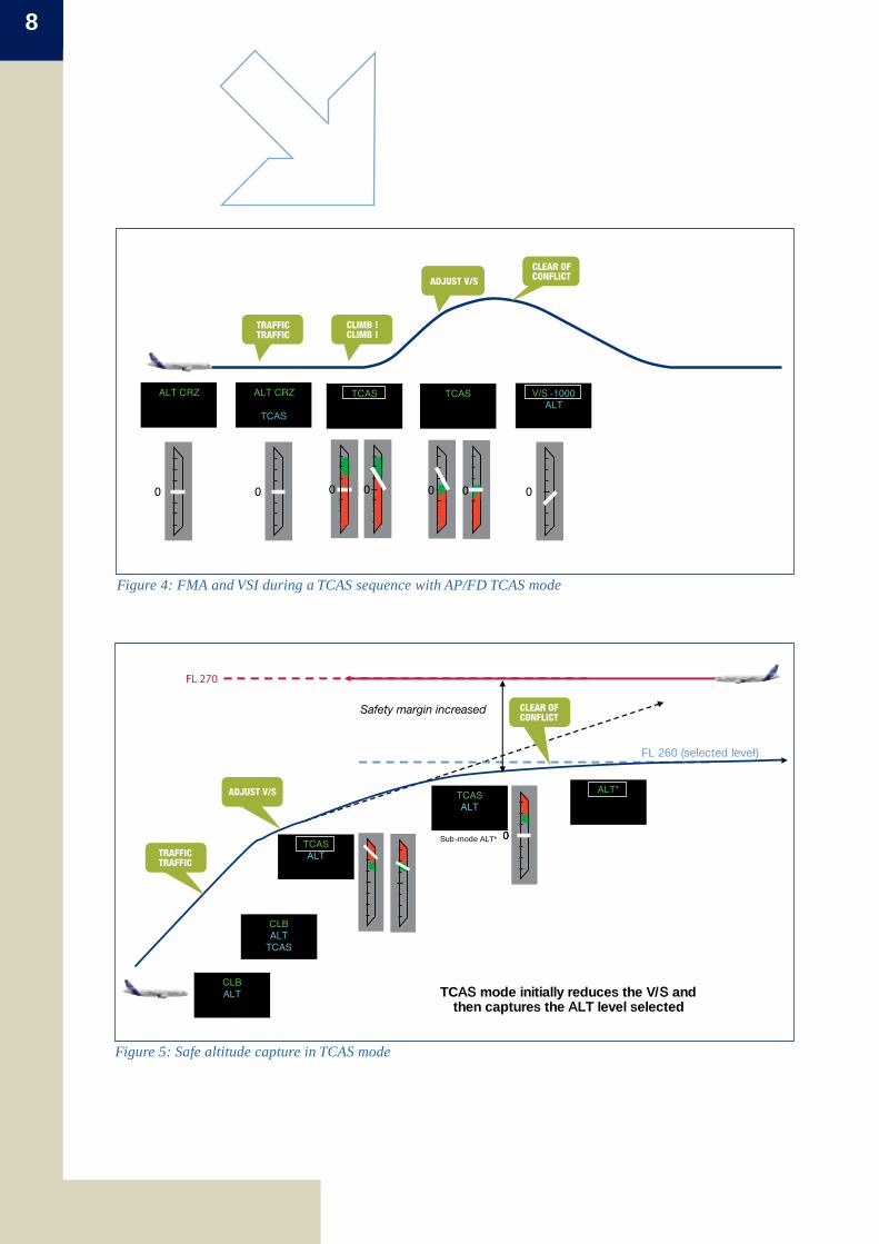
– All previously armed longitudinal modes areautomatically disarmed, except the altitudecapture mode (ALT*) in case of an “ADJUSTV/S” alert. This prevents an undue altitudeexcursion: indeed, in this type of RA, reaching0 ft/min is always safe, as this value is neverwithin the red vertical speed zone. Therefore,if the altitude capture conditions are met, theTCAS mode will safely allow to capture thetargeted flight level
– The Auto Thrust engages in speed controlmode (SPEED/MACH) to ensure a safe speedduring the maneuver
– The current engaged lateral mode remainsunchanged.
– The current engaged lateral mode remainsunchanged.
• Once Clear of Conflict, vertical navigation isresumed as follows : – The AP/FD longitudinal mode reverts to
the “vertical speed” (V/S) mode, with asmooth vertical speed target towards theFCU target altitude. The ALT mode is armedto reach the FCU target altitude (ATCcleared altitude)
– If an altitude capture occurred in the courseof a TCAS RA event, once Clear of Conflict,the AP/FD longitudinal mode reverts to thealtitude capture (ALT*) or to the altitude hold(ALT) mode
– The lateral mode remains unchanged.
• In case of Preventive RA (e.g.” MONITOR V/S”aural alert), the aircraft vertical speed is initiallyout of the red VSI zone. The requirement is tomaintain the current vertical speedConsequently:– The TCAS longitudinal mode engages to maintain
the current safe aircraft vertical speed target– All previously armed longitudinal modes are
automatically disarmed, except the altitudecapture mode (ALT*). Indeed, as for an“ADJUST V/S” RA, levelling-off during aPreventive RA will always maintain the verticalspeed outside of the red area. So if the altitudecapture conditions are met, the TCAS modewill allow to safely capture the targeted level,thus preventing an undue altitude excursion
– The Auto Thrust engages in speed controlmode (SPEED/MACH) to ensure a safe speedduring the maneuver
7Safety FirstThe Airbus Safety Magazine
# 07 February 2009
"Adjust V/S, Adjust"
1FD2 A /THR
TCAS
SPEED TCAS NAV AP1 1FD2 ATHR
SPEED TCAS AP1 1FD2ATHR
Figure 3: PFD upon a Corrective TCAS RA with AP/FD TCAS mode
8
ALT CRZ TCASALT CRZ
TCAS
V/S -1000ALT
00
TCAS
00 0 0 0
TRAFFICTRAFFIC
CLIMB ! CLIMB !
CLEAR OF CONFLICTADJUST V/S
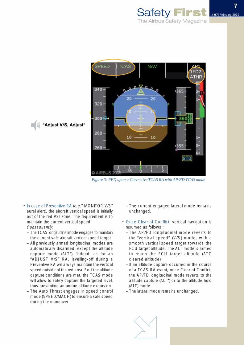
Figure 4: FMA and VSI during a TCAS sequence with AP/FD TCAS mode
CLBALT
CLBALT
TCAS
TCASALT
Sub-mode ALT*
TCASALT
ALT*
FL 260 (selected level)
00
TCAS mode initially reduces the V/S and then captures the ALT level selected
Safety margin increased
FL 270
TRAFFIC
ADJUST V/S
CLEAR OFCONFLICT
TRAFFIC
Figure 5: Safe altitude capture in TCAS mode
9Safety FirstThe Airbus Safety Magazine
# 07 February 2009
The AP/FD TCAS mode was demonstrated to alarge panel of pilots from various airlines, and wasperceived by them as a very simple and intuitivesolution. It was deemed to be consistent with theAirbus cockpit philosophy and Auto Flight system.
All agree that the AP/FD TCAS mode representsa safety improvement.
5 Certification scheduleThe certification of the AP/FD TCAS mode functionis expected:• On the A380: by May 2009• On the A320 family:
– with CFM engines, by end 2009– with IAE engines, by July 2010
• On the A330/A340, depending on the aircrafttype, from the beginning of 2010 (A330 PW/RR)to the end of 2011 (A340-500/600).
The certifcation dates for all required retrofitstandards are not yet frozen.
4 Operationalbenefits
The operational benefits of the AP/FD TCAS modesolution are numerous; the system addressesmost of the concerns raised by in-line experiencefeedbacks:• It provides an unambiguous flying order to the
pilot• The flying order is adjusted to the severity of the
RA; it thus reduces the risks of overreactionby the crew, minimizes the deviations fromtrajectories initially cleared by ATC, and adaptsthe load factor of the maneuvre
• The availability of the AP/FD TCAS mode makesit possible to define simple procedures for theaircrews, eliminating any disruption in their flyingtechnique: the procedure is simply to monitorthe AP, or to manually fly the FD bars, when theTCAS mode engages, while monitoring the VSI.
By reducing the crews’ workload and stresslevel, the AP/FD TCAS mode should thereforesignificantly reduce: • Inappropriate reactions in case of Resolution
Advisory (late, over or opposite reactions)• Misbehaviours when Clear of Conflict• Lack of adequate communications with ATC.
Note: For ATC controllers, the AP/FD TCASmode is totally transparent in terms ofexpected aircraft reactions.
Braking systemcross connections
By: Thierry THOREAUDirector, Flight Safety
1 Introduction
The braking system cross connections havegenerated a few incidents over the years. Theworst case experienced on the Airbus fleet furtherto a case of braking system cross connections,led the airplane to stop around 150 feet fromthe extended runway centerline. An emergencyevacuation was initiated and everybody escapedsafely, without serious injuries. The aircraftsustained some damages.
This document will present:• The two types of cross connections reported
and their consequences • The existing prevention measures • The operational procedure to mitigate them• And finally the improvements already
implemented, or contemplated.
Increased awareness on these possible maintenanceerrors should help avoiding or mitigating furtherevents.
2 Type of eventsreported on theSingle Aisle aircraftfamily
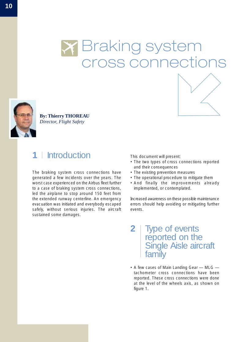
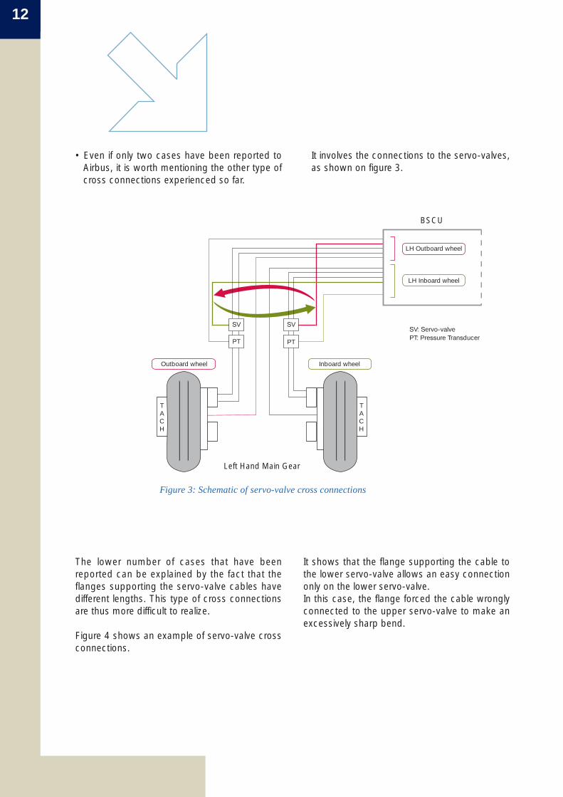
• A few cases of Main Landing Gear — MLG —tachometer cross connections have beenreported. These cross connections were doneat the level of the wheels axis, as shown onfigure 1.
10
11Safety FirstThe Airbus Safety Magazine
# 07 February 2009
LH Outboard wheel
LH Inboard wheel
SV: Servo-valveSV
PT
SV
PT PT: Pressure Transducer
Inboard wheelOutboard wheel
TACH
TACH
Cross connected cable
Braking & SteeringControl Unit – BSCU –
Left Hand Main Gear
Tachometer
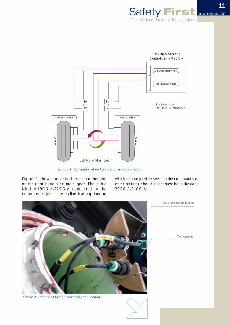
which can be partially seen on the right hand sideof the picture), should in fact have been the cable20GG-A/21GG-A.
Figure 2 shows an actual cross connectionon the right hand side main gear. The cablelabelled 19GG-A/22GG-A connected to thetachometer (the blue cylindrical equipment
Figure 1: Schematic of tachometer cross connections
Figure 2: Picture of tachometer cross connections
12
It involves the connections to the servo-valves,as shown on figure 3.
• Even if only two cases have been reported toAirbus, it is worth mentioning the other type ofcross connections experienced so far.
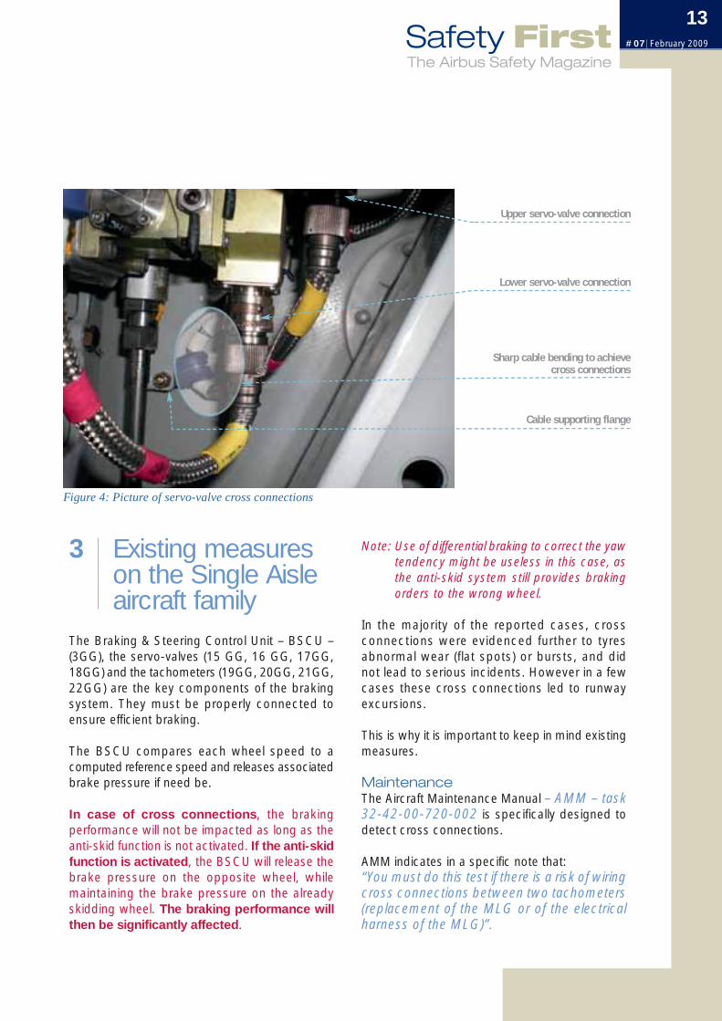
It shows that the flange supporting the cable tothe lower servo-valve allows an easy connectiononly on the lower servo-valve.In this case, the flange forced the cable wronglyconnected to the upper servo-valve to make anexcessively sharp bend.
The lower number of cases that have beenreported can be explained by the fact that theflanges supporting the servo-valve cables havedifferent lengths. This type of cross connectionsare thus more difficult to realize.
Figure 4 shows an example of servo-valve crossconnections.
SV: Servo-valvePT: Pressure Transducer
SV
PT
SV
PT
Inboard wheelOutboard wheel
TACH
TACH
LH Outboard wheel
LH Inboard wheel
BSCU
Left Hand Main Gear
Figure 3: Schematic of servo-valve cross connections
13Safety FirstThe Airbus Safety Magazine
# 07 February 2009
Note: Use of differential braking to correct the yawtendency might be useless in this case, asthe anti-skid system still provides brakingorders to the wrong wheel.
In the majority of the reported cases, crossconnections were evidenced further to tyresabnormal wear (flat spots) or bursts, and didnot lead to serious incidents. However in a fewcases these cross connections led to runwayexcursions.
This is why it is important to keep in mind existingmeasures.
Maintenance The Aircraft Maintenance Manual – AMM – task32-42-00-720-002 is specifically designed todetect cross connections.
AMM indicates in a specific note that:“You must do this test if there is a risk of wiringcross connections between two tachometers(replacement of the MLG or of the electricalharness of the MLG)”.
3 Existing measures on the Single Aisleaircraft family
The Braking & Steering Control Unit – BSCU –(3GG), the servo-valves (15 GG, 16 GG, 17GG,18GG) and the tachometers (19GG, 20GG, 21GG,22GG) are the key components of the brakingsystem. They must be properly connected toensure efficient braking.
The BSCU compares each wheel speed to acomputed reference speed and releases associatedbrake pressure if need be.
In case of cross connections, the brakingperformance will not be impacted as long as theanti-skid function is not activated. If the anti-skidfunction is activated, the BSCU will release thebrake pressure on the opposite wheel, whilemaintaining the brake pressure on the alreadyskidding wheel. The braking performance willthen be significantly affected.
Upper servo-valve connection
Lower servo-valve connection
Cable supporting flange
Sharp cable bending to achievecross connections
Figure 4: Picture of servo-valve cross connections
14
It is worth mentioning that in these circumstances,it might be appropriate for the flight crew tomaintain full reverse thrust below the SOPminimum recommended speed for full reverseuse. The Standard Operating Procedure forLanding will be updated accordingly at the nextgeneral revision to indicate that, in case ofemergency, maximum reverse thrust might beused until a complete stop.
OperationsShould there be cross connections and an anti-skid function activation during the landing roll, thecrew will perceive two things:• A yawing tendency, and• An unusually small deceleration.
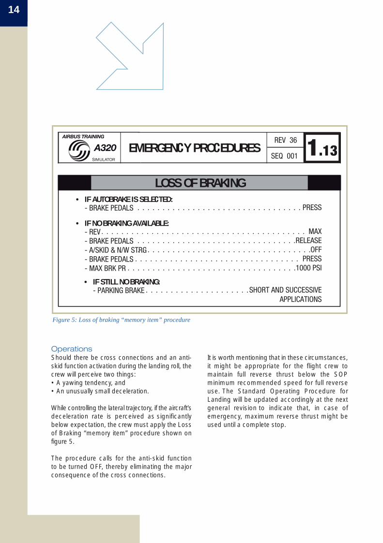
While controlling the lateral trajectory, if the aircraft’sdeceleration rate is perceived as significantlybelow expectation, the crew must apply the Lossof Braking “memory item” procedure shown onfigure 5.
The procedure calls for the anti-skid functionto be turned OFF, thereby eliminating the majorconsequence of the cross connections.
EMERGENCY PROCEDURES 1.13REV 36
SEQ 001
• IF AUTOBRAKE IS SELECTED:. . . . . . . . . . . . . . . . . . . . . . . . . . . . . . . . . PRESS- BRAKE PEDALS
• IF NO BRAKING AVAILABLE:. . . . . . . . . . . . . . . . . . . . . . . . . . . . . . . . . . . . . . . . . MAX- REV
• IF STILL NO BRAKING:. . . . . . . . . . . . . . . . . . . . .SHORT AND SUCCESSIVE
APPLICATIONS- PARKING BRAKE
. . . . . . . . . . . . . . . . . . . . . . . . . . . . . . . .RELEASE- BRAKE PEDALS
. . . . . . . . . . . . . . . . . . . . . . . . . . . . . . . . . . .OFF- A/SKID & N/W STRG . . . . . . . . . . . . . . . . . . . . . . . . . . . . . . . . . PRESS- BRAKE PEDALS
. . . . . . . . . . . . . . . . . . . . . . . . . . . . . . . . . .1000 PSI- MAX BRK PR
A320SIMULATOR
AIRBUS TRAINING
LOSS OF BRAKING
Figure 5: Loss of braking “memory item” procedure
REFERENCEOperator Information Telex (OIT) ref 999.0133/07/LBRev 01 issued on the 30th of April 2008, remindsthe operators to strictly adhere to the AMMtask 32-42-00-720-002 "Functional Test ofTachometers” whenever it needs to be applied.
15Safety FirstThe Airbus Safety Magazine
# 07 February 2009
4 Maintenancedocumentationimprovements
Recently, the AMM task 32-42-00-720-002 hasbeen amended to include the monitoring of thebrake’s wear pin and brake unit deflection, inaddition to the previous monitoring of the brake’spiston movements, as additional means todetermine proper brake operation.
This task is now also required further to theinstallation of servo-valves.
5 Futureimprovements
• The Trouble Shooting Manual (TSM) will beenhanced to include an entry point in case oftyre flat spot(s), to look for possible crossconnections
• On the Single Aisle (SA) family, cable colourcoding is currently under review to avoid crossingcables.
Note: All SA family changes• introduced (addition of warnings in AMM,
monitoring of the brake’s wear pin and brakeunit deflection to determine brake operation)
• planned (TSM entry in case of tyre flat spots)• or under review (cable colour coding)are being considered as well on the other familiesof Airbus aircraft fitted with boogie gears. On thesetypes of landing gear, the consequences of crossconnections are reduced compared to the diaboloversions.
6 ConclusionCrossed cables in the braking system have, in thepast, caused incidents. It is therefore importantto comply strictly with the published maintenanceprocedure.
Pilots facing a situation where the airplane yawsto one side and the aircraft’s deceleration rate isperceived as significantly below normal, maysuspect brake cross connections. They shouldapply the Loss of Braking “memory item”, whichcalls for the anti-skid function to be turned OFF.
16
Upset RecoveryTraining Aid,Revision 2
By: Larry ROCKLIFFV.P., Training and Flt. Ops Support, Customer Services, Airbus Americas
1 IntroductionThe original industry upset recovery training wasdelivered to the aviation community ten years ago.The genesis of this reference was a discovery thatmany pilots had progressed along their career andhad never been educated in recognition andrecover from upsets or unusual attitudes. Ten yearslater, the accident/incident rate due to failure torecover from an upset, remains among the topstatistics to work on. There are various reasonsfor this, not the least of which is a regulatory basethat allows to add training modules to an operator’sprogram, but is less agreeable to remove modulesthat have much less significance in the operatingenvironment of today.
In recent years, there have been several accidentsand incidents that have occurred in the high altitudeenvironment. Odd as it may seem, causal factorsfrom several investigations have been a lack ofunderstanding of phenomena associated withoperating a jet aircraft in the high altitudeenvironment. To respond to this shortfall in a piloteducation, the FAA asked Airbus and Boeing to
convene an industry group to define a training aidspecific to high altitude operations. The resulthas been a collaborative effort that consistedof manufacturer, airline, safety, regulatory,industry trade, and educational organizationalrepresentatives both domestic, within the UnitedStates, and international in scope to arrive at adocument that addresses the problem.
Consensus from the group was to amplifyinformation and guidance vis a vis high altitudealready embedded in the existing IndustryUpset Recovery Training Aid and deliver it asRevision 2. This is now available to operators onhttps://w3.airbusworld.com.
In addition, because the FAA requested a specificreference for high altitude to respond to NTSBrecommendations, it was decided to also providea separate stand alone supplement to specificallyaddress high altitude phenomena. This is aseparate appendix, which is contained in the backof the Training Aid.
Containing the startle factor applies to everysituation a pilot may encounter, regardless of highaltitude or sea level operating environment. It is anatural reaction; perhaps even reflex action, towant to do something when one is startled.Reactively, disconnecting an Auto Pilot and makingun-calibrated open loop rudder and/or controlyoke or sidestick inputs will never be the correctreaction and will almost always lead to an amplifiedabnormal situation. It is in this area that pilots mustdevelop skills to discipline themselves from puttingtheir hands and/or feet into motion, without firstunderstanding what is going on and what thepotential consequences of their actions will be.Disconnecting the Auto Pilot under effort in a reflexaction is particularly significant as it generally resultsin a large control input. Indeed, many high altitudeupsets would never have become upsets hadpilots contained the startle factor. This is a criticalarea of human factor development that cannot beoverstated.
Recognize and confirm the situation is essentialfor the pilot to determine what recovery action isnecessary. Some situations develop quite slowly inwhich case, the crew will have ample time to assessand decide upon a course of action. However, somemay occur nearly instantly, and in these cases thepilot/crew must determine what is happening totheir energy state and what is happening to theirtrajectory. It may not be easy, but it is critical in orderfor the crew to decide what response they will needto take. In the same way that many engines havebeen un-necessarily shutdown before sufficientinformation had been considered, so too, have highaltitude upsets been created, due to reacting to onlypart of the available information. This is a broad areathat cannot be distilled into the scope of this article,but sufficient to say that a corrective action cannotbe contemplated without consideration of whatthe pilot/crew is responding to. The link betweencontaining the startle factor, recognizing andconfirming the situation, can be fused together toallow the pilot to apply the third and always essentialtake away point.
2 Goal
The goal of Revision 2 is to focus on specificeducation for pilots so they have the knowledgeand skill to adequately operate their airplanes andprevent upsets in a high altitude environment. Thisincludes educating pilots so they can develop theability to recognize and prevent an impending highaltitude problem and increase the likelihood of asuccessful recovery from a high altitude upsetsituation should it occur.
As surprised as regulators and industry was todiscover in the 1990s that many pilots did not havethe knowledge and skills to recognize and recoverfrom any upset or unusual attitude, it came equallyas baffling to learn that pilots had exceedinglylimited knowledge and abilities to handle theirairplanes in the high altitude environment in spiteof the fact they operate in this area over 98% oftheir flight time experience. Indeed, many pilotshave never had the opportunity (or requirement)to operate their aircraft in the high altitudeenvironment with an Auto Pilot off to experiencethe differences.
3 Take AwayThere is considerable content within the TrainingAid Revision 2 and Airbus recommends thatoperators refresh their knowledge and skills witha view to introduce primary and/or refresher trainingfor their crews. With all the information availableto the training departments, the take away to eachand every pilot has been distilled into three simpleguidelines:
• Contain The Startle Factor• Recognize and Confirm the Situation• Very Small Control Inputs
17Safety FirstThe Airbus Safety Magazine
# 07 February 2009
18
290 knots indicated air speed (KIAS) at sea level,the same change in attitude at 290 KIAS (490 knots true air speed) at 35,000 ft would bealmost 900 fpm. This characteristic is essentiallytrue for small attitude changes, such as the kindused to hold altitude. It is also why smooth andsmall control inputs are required at high altitude,particularly when disconnecting the Auto Pilot (anAuto Pilot disconnection by overriding it on the yokeor sidestick controller will very likely cause large andexcessive control inputs). Put in fundamental pilotingterms, inappropriate control inputs due to un-contained startle factor without consideration forwhat is actually occurring, can almost certainlycause an upset to become exaggerated, or indeedprecipitate one that didn’t exist in the first place.Simply stated, all control inputs must be in the formof control pressures versus control deflections.Incidentally, this is identical to the relationship in thelarger movements on an automobile steering wheelwhen nearly stopped as opposed to the tinypressures warranted while at high speeds. Imaginethe result of a large steering wheel deflection athighway speeds…
4 Airbus Policytoward UpsetRecovery Training
Airbus policy has been consistent since theoriginal Industry Upset Recovery Training Aid wasoffered in 1998. Airbus believes it is practical andencouraged to educate all pilots to understandthe principles of airplane upsets and how to avoidthem. The dynamics of airplane upsets at lowaltitude or high altitude are so broad that definingsimplistic procedures or techniques are notappropriate. To that end, upset recovery trainingis encouraged in the context of awareness trainingversus procedure training.
Very small control inputs cannot be overstated.Open loop, or arbitrary large scale deflectionsmust be avoided at any altitude. The relationshipbetween control surface deflection and trajectorychange is amplified at high altitude. • The airspeed at high altitude is generally higher
than the one pilots are used to fly at manually.Therefore, a reflex action giving the same controlsurface deflection will result in a much higherload factor than initially expected.
• For the same control surface movement atconstant airspeed, an airplane at 35,000 ftexperiences a higher pitch change than anairplane at 5,000 ft because there is lessaerodynamic damping. Therefore, the changein angle of attack is greater, creating more liftand a higher load factor.
• Moreover, if the input is large enough, pitch upmay happen, amplifying the formerly describedeffect and buffeting may occur, creating asecond startle factor that may trigger anotherlarge reaction in the opposite direction.
If the control system is designed to provide a fixedratio of control force to elevator deflection, it willtake less force to generate the same load factoras altitude increases. On many modern airplanes with classical, nonreversible flight controls, the control force toelevator ratio is varying with airspeed so as to giveroughly a constant force for the same load factorall over the flight envelope. This is even more truefor fly-by-wire airplanes flying with C* pitch controllaw where sidestick deflection is actually a loadfactor demand.
A similar discussion could be held for the yaw axiswith rudder inputs.
Nevertheless, and whatever the flight controlsystem, an additional effect is that, for a givenattitude change, the change in rate of climb isproportional to the true airspeed. Thus, for anattitude change for 500 ft per minute (fpm) at
5 Summary Airbus has been a supporter of educating pilotsto recognize and avoid airplane upsets. Thoughthis knowledge and associated skills should havebeen acquired during earlier pilot training and notairplane type rating training, it is important torecognize that a knowledge gap exists within thepilot community and Airbus has been a leader inworking with industry to arrive at a solution.
Contain the startle factor, recognize and confirmthe situation and correct making the smallestcontrol inputs/pressures possible to arrest anydivergence in order to recover. These three pointsare powerful, positive “take aways”…
Moreover, Airbus does not support the use offull flight simulators to conduct upset recoverytraining. Although excellent training tools withinthe normal operating environment and envelopethe pilot/crew experiences in his/her duties,simulators have many limitations that createenormous opportunities for negative training.Airbus believes the risk of producing significantnegative training far outweighs the possible benefitthat might be achieved.
High altitude exercises as proposed in the mostrecent Revision 2 of the Industry aid, is consistentwith Airbus training policy. Because the scenariosrecommended are focused towards recognizinga developing situation so the pilot/crew can arriveat a solution prior to entering an upset, the use ofsimulators in these scenarios are appropriate.
Some operators may still decide to use simulatorsto conduct upset recovery training. In these cases,Airbus recommends to only use the simulatorswith the motion systems selected off. This is notto protect the serviceability of the equipment dueto large motion movements toward the stops.Rather, it is an attempt to minimize the likelihoodof negative training due to incorrect motion cuesand lack of accelerations. Indeed, positive re-enforcement derived from negative training, is themost difficult situation to manage. A pilot/crewshould walk away from a training event withpositive re-enforcement. However, if similarconditions taught in a simulator are experiencedin an airplane, there could be large differences inhow the airplane responds to the pilot inputs andconsequences can be severe and unrecoverable.Finally, Airbus does not support intentionallysuppressing normal law in order to facilitate upsetconditions.
19Safety FirstThe Airbus Safety Magazine
# 07 February 2009
20
Fuel pumps left in OFF position
By: Frédéric COMBESDirector, Flight Safety
1 Introduction
An A320 encountered a dual engine rollback, afterthe aircraft levelled off at Flight Level 380, as aresult of fuel starvation.The aircraft was dispatched with the center tankempty. Both wing tank fuel pushbutton switcheshad been left in the OFF position from engine start.Interesting lessons may be learned from this event.
2 Investigation
An official investigation was conducted with theconcerned Investigations Board, the airline, enginesupplier and Airbus.
Five different hypothesis have been examined:• Adverse weather conditions• Fuel contamination• Aircraft fuel system anomaly• Engine misbehaviour• Fuel pumps left in the OFF position.
The following data have been investigated:• Engines Full Authority Digital Engine Control
(FADEC) Non Volatile Memories• Digital Flight data Recorder (DFDR) engine main
parameters • Post Flight Report (PFR).
Analysis of all the available data allowed to ruleout the first four hypothesis. Indeed:• There was no indication that inclement weather
condition could have contributed to the event• The fuel sampling analysis confirmed that the
fuel was not contaminated• The data recorded within the engine computer
allowed to rule out any control system/engineissue
• The aircraft’s recorded data and troubleshootingperformed on the aircraft, did not highlight anyevidence of failure in the following systems:– Fuel– Electrical generation and distribution – Autoflight.
The only remaining scenario was therefore thatall fuel pumps had remained switched-off fromthe engine start until the time of the dual enginerollback.
21Safety FirstThe Airbus Safety Magazine
# 07 February 2009
3 Analysis of the event
Operations Engineering Bulletin 178“OPERATION OF CENTER TANKPUMPS”The OEB was applicable to the aircraft concernedby this event. During the refuelling, all fuel pumpswere set to OFF, in accordance with OEB 178.
This OEB was issued to avoid having the centertank pump in operation if not fully immersed. It calls for:• All fuel pumps to be in the OFF position before
and during the refuelling• The wing tank pumps to be set ON after the
refuelling• The center tank pumps to be left OFF, if the total
fuel on board is less or equal than 12 000 kg.
Note: 1. OEB 178 is applicable to someA318/A319/A320 aircraft with acenter tank.
2. OEB 180 “OPERATION OF FUELPUMPS”, applicable to some A321 aircraft, was also issued toavoid having wing fuel pumps runningif not fully immersed during fuelloading operation: It notably calls forall wing fuel pumps to be turned OFFbefore refuelling.
The available data allowed to confirm the following:1) During the engine start sequence all fuel
pumps were left in the OFF position, leadingto the triggering of the following ECAMCautions:
FUEL L TK PUMP 1+2 LO PRFUEL R TK PUMP 1+2 LO PR
The crew cleared both Cautions but left the fuelpumps in the OFF position.As a consequence, both engines were beinggravity fed during the engine start, take-off andclimb phases of the flight.
2) The behaviour of the engines was normal untilthe aircraft reached FL380, some 23 minutesafter take-off. At that point, both engines rolledback, leading to:• The Mach Number to decrease from M0.78
to M0.63• The disconnection of the Electrical Generators
1&2 (Engines 1&2 N2 being below 53%)• The Ram Air Turbine deployment (Emergency
Electrical Configuration).
3) The aircraft started to descend and the crewdeclared an Emergency.At FL 320, the engines were recovered leadingto an automatic re-connection of both ElectricalGenerators. The crew then decided to turn backto the departure airport where an uneventfullanding was performed.This scenario was confirmed through a flighttest done on an Airbus A320 production aircraft.
22
The excess air vents into the fuel tanks and enginefuel lines.At some point, the quantity of vapour present inthe fuel, when it reaches the engine, may exceedthe engine inlet maximum allowable vapour /liquid ratio and the operation of the engines iscompromised. In the example illustrated in thisarticle, the airplane was able to reach FL380before the engines eventually rolled back.
However, the precise altitude at which engines willexperience fuel starvation depends on a numberof factors, including saturation level of air in thefuel, temperature and rate of climb.
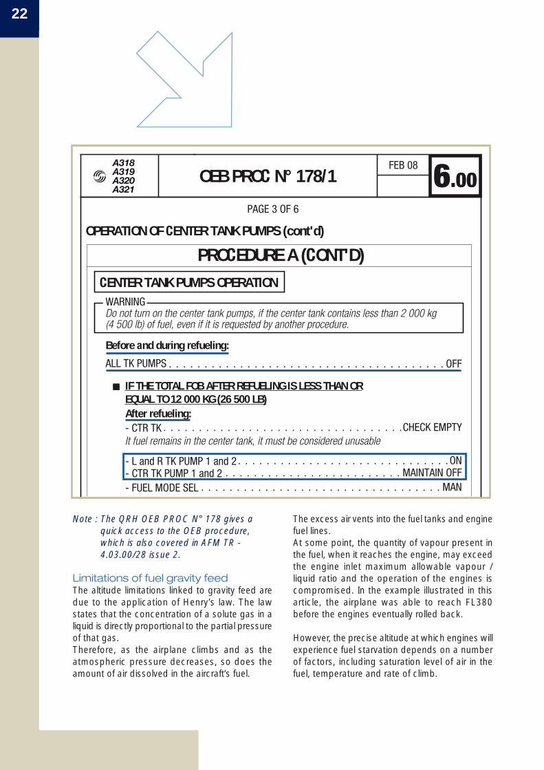
Note : The QRH OEB PROC N° 178 gives aquick access to the OEB procedure,which is also covered in AFM TR -4.03.00/28 issue 2.
Limitations of fuel gravity feedThe altitude limitations linked to gravity feed aredue to the application of Henry’s law. The lawstates that the concentration of a solute gas in aliquid is directly proportional to the partial pressureof that gas.Therefore, as the airplane climbs and as theatmospheric pressure decreases, so does theamount of air dissolved in the aircraft’s fuel.
Before and during refueling:
OPERATION OF CENTER TANK PUMPS (cont'd)
CENTER TANK PUMPS OPERATION
. . . . . . . . . . . . . . . . . . . . . . . . . . . . . . . . . . . . . . . OFFALL TK PUMPS
PAGE 3 OF 6
Do not turn on the center tank pumps, if the center tank contains less than 2 000 kg(4 500 lb) of fuel, even if it is requested by another procedure.
• IF THE TOTAL FOB AFTER REFUELING IS LESS THAN OREQUAL TO 12 000 KG (26 500 LB)After refueling:
. . . . . . . . . . . . . . . . . . . . . . . . . . . . . . . . . .CHECK EMPTY- CTR TK
. . . . . . . . . . . . . . . . . . . . . . . . . . . . . .ON- L and R TK PUMP 1 and 2 . . . . . . . . . . . . . . . . . . . . . . . . . MAINTAIN OFF- CTR TK PUMP 1 and 2
. . . . . . . . . . . . . . . . . . . . . . . . . . . . . . . . . . MAN- FUEL MODE SEL
It fuel remains in the center tank, it must be considered unusable
OEB PROC N° 178/1 6.00FEB 08
PROCEDURE A (CONT'D)
WARNING
A318A319A320A321
The PNF then performs the action and requestspermission to clear the failure.The PF will first check to ensure that the action hasbeen completed, then announce, “Clear ECAM”.
Fuel pumps left in OFF positionThe following three barriers were available toalert the crew of the abnormal configuration theywere flying in:
• First barrier:At the beginning of the Cockpit Preparationchecklist for the Overhead Panel, the SOPsrequest the crew to extinguish all white lights(pushbutton switches) on the overhead panel,as applicable during the scan sequence. Thisensures that both the center tank and wing tankpushbutton switches are selected to the ONposition prior to flight, except for the centertank if OEB 178 applies.With the center tank and wing tank fuel pumpsl in the OFF position, this is how the overheadpanel would look like; notice the six illuminatedwhite pushbutton lights:
Considering the worst case operating conditions,the A320 FCOM 3.02.28/QRH 2.09 paperprocedure has retained three different scenarios: • The airplane is on gravity feed shortly after take-
off, in which case the gravity fuel feed ceiling islimited to FL150 or 7 000 feet above the airport
• The airplane switches to gravity feed with a Flighttime above FL300 being less than 30 minutes,in which case the ceiling is limited to FL300
• The airplane switches to gravity feed with a Flighttime above FL300 exceeding 30 minutes, inwhich case the ceiling is the current FL.
4 Standard OperatingProcedures
ECAM task sharing rulesThis event serves to highlight the importanceof adhering to the ECAM operational philosophy. The first pilot, who notices an ECAM Caution orWarning, announces the title of the failure. ThePilot Flying (PF) then orders “ECAM Action”, andthe Pilot Non Flying (PNF) confirms the action.This process ensures that bothcrew members are aware of thefailure, and that they share acommon understanding of theactions to be undertaken.
23Safety FirstThe Airbus Safety Magazine
# 07 February 2009
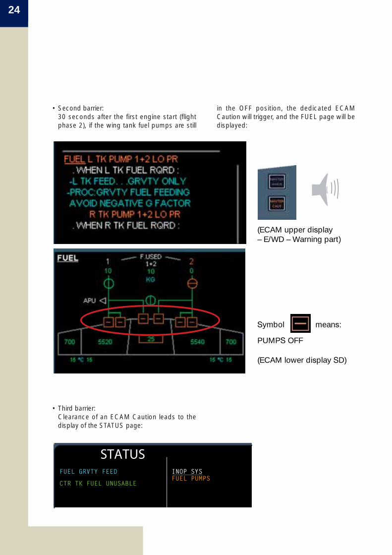
• Third barrier:Clearance of an ECAM Caution leads to thedisplay of the STATUS page:
24
in the OFF position, the dedicated ECAMCaution will trigger, and the FUEL page will bedisplayed:
• Second barrier:30 seconds after the first engine start (flightphase 2), if the wing tank fuel pumps are still
(ECAM upper display– E/WD – Warning part)
(ECAM lower display SD)
Symbol means:
PUMPS OFF
STATUSFUEL GRVTY FEED INOP SYS
FUEL PUMPSCTR TK FUEL UNUSABLE
5 Enhancements
Flight warning Computer (FWC)Airbus is working on future enhancements in thenext FWC standard H2F5 (certification plannedby mid 2009). Indeed, the TAKE OFF CONFIGwill be improved to monitor as well the fuelpumps, hydraulic pressure, IDG disconnection,and electrical generators.For example, if the fuel pumps are left in the OFFposition, this new FWC standard will recall thefollowing ECAM Caution :
FUEL L TK PUMP 1+2 LO PRFUEL R TK PUMP 1+2 LO PR
Information concerning OEB 178 and OEB 180:Operators for which OEB 178 and/or OEB 180apply, may cancel them by the accomplishmentof the mandated Service Bulletin 28-1159-00 (thisSB involves only 2 hours of elapsed time).
6 Conclusion
Existing barriers (white lights on the overheadpanel, ECAM Caution, audio warning, status pagedisplay on the System Display) were available toprevent the crew overlooking the fuel pumps inthe OFF position.
Further barriers will be included with the proposedenhancements:• Addition of some system monitoring within FWC
standard H2F5• Cancellation of OEB 178 and OEB 180 with the
implementation of the modification referencedin SB 28-1159-00.
Additionally, the following more general lessonsmay be learned from this event:
• ECAM task sharing rules should be followedbefore clearing Cautions or Warnings
• Design features are not meant, and never will,to replace effective briefings.
25Safety FirstThe Airbus Safety Magazine
# 07 February 2009
26
Avoiding DualBleed Loss
By: Patrick GRAVEGroup ManagerPneumatics, Ice and Fire Protection SystemsCustomer Services
1 Introduction
Over the past years, the A320 family fleetexperienced a significant number of dual air enginebleed losses. The consequences of these lossesranged from in-flight turn backs shortly after take-off, to full blown cabin depressurization events andflight diversions. The aim of this article is to present the typicalcauses of the dual bleed losses and to explainhow:• The crew may mitigate the operational
consequences of this type of occurrence byapplying the pertinent procedures
• New maintenance and design improvementsshould reduce the number of such events in thefuture.
We are confident that the correct application ofthe above procedures and improvements shouldhelp airlines to limit occurrences of dual bleed lossincidents.
2 Description of thepneumatic system
The main purpose of the dual bleed air system isto provide the air conditioning system with airregulated in both pressure and temperature.They also supply various air system consumerssuch as :
• Wing anti-ice protection• Engine starter• Hydraulic reservoir and water tank pressurizatio n.
Christophe MATHEEngineer A320/A330/A340Operational StandardsCustomer Services
27Safety FirstThe Airbus Safety Magazine
# 07 February 2009
The bleed air system is installed in the nacelleand pylon of each engine and includes:
• For the pressure regulation:– An Intermediate Pressure Bleed Check Valve
(IPCV) – A High Pressure Bleed Valve (HPV)– An Over Pressure Valve (OPV) – A Pressure Regulator Bleed Valve (PRV),
which is commanded by a TemperatureLimitation Thermostat (TLT).The TLT will order the PRV to reduce thepressure in the system in case of over-temperature.
• For the temperature regulation:– A precooler exchanger (PCE)– A Fan Air Valve (FAV), which is commanded
by a Temperature Control Thermostat (TCT)– The TCT will order the FAV to increase air flow
from the fan in case of over-temperature.
• For the system monitoring:– A Bleed Monitoring Computer (BMC).
APU
APU bleed valveTo cargoheating
APU check valve
Wing leading edge ventilation
Wing anti-ice valve
To wing anti-ice
Pre-cooler
Engine HP/IP bleedFan air bleed
HP groundconnector
Cross-bleed valve
To varioussystems
Wing anti-ice valve
To wing anti-ice To air conditioning packs
Figure 1: Pneumatic system layout
28
To aircraft systems
BMC
PCE
OVERBOARD
TCT
FAVOPV
TO STARTERVALVE
pylonNacelle
PRV
IPCV
FAN
IPHP
HPV
TLTTemp
3 Typical failurescenario
The dual bleed loss events usually happen whenone bleed fails, resulting in the remaining bleed onthe other engine to compensate for it.
The augmented flow of warm air from the enginecore leads to a corresponding increase in the flowof cold air from the Fan to the Precooler.
In case of one engine bleed loss, the remainingbleed fails when the Fan Air Valve (FAV) does notlet enough cold air reach the Precooler (PCE). This causes the temperature downstream of thePCE to reach the 260°C (500°F) over-temperaturethreshold, which induces the automatic closure ofthe bleed system.
Figure 2: Main components description
29Safety FirstThe Airbus Safety Magazine
# 07 February 2009
This excessive rise in temperature is caused mainlyby either: • Leakage of the TCT to FAV sense line• TCT drift / failure• Or FAV leakage / failure.
NOTE: In-service experience has shown thatthe root cause of over-temperatureis often linked to a combinationof the above factors.
Other possible causes are: • Temperature sensor failure• Wiring failure.
4 Operationalprocedure to be applied
In the above scenario, the failure of the first bleedsystem leaves the second engine bleed to supplyall the aircraft consumers. This bleed, in turn, islost due to excessive demand. After the failure of both bleed systems, theAIR DUAL BLEED FAULT paper procedure (QRHpage 2.02 and FCOM 3.02.36 page 3) thereforerecommends to initiate a rapid descent to FL200and to reduce air demand, before attempting therecovery of the second bleed system.
Assuming that both PACKS are operative, the airdemand is reduced by shutting OFF the PACKon the side of the first affected bleed system.The flight crew should then press twice theENG BLEED pushbutton on the overhead panelassociated to the second engine bleed, in orderto reset it.
Figure 3: Extract of Quick Reference Handbook page 2.02
• If both packs are available:
. . . . . . . . . . . . . . . . . . . . . . . . . . . . . . . . . . . . . . . . INITIATE
If both packs are operative, it can be suspected that the second bleed system failed due to excessive demand. Recovery of the second failed engine bleed may be attempted.
– DESCENT Descend rapidity to FL200* so that the bleed supply may be supplied by the APU, if thebleed system recovery is not successful.
• IF ENG 1 BLEED is lost first:. . . . . . . . . . . . . . . . . . . . . . . . . . . . . . . . . . . . . . . .OFF- PACK 1
• IF ENG 2 BLEED is lost first:. . . . . . . . . . . . . . . . . . . . . . . . . . . . . . . . . . . . . . . .OFF- PACK 2
. . . . . . . . . . . . . . . . . . . . . . . . . . . . . . . . . . . ON- ENGINE 1 BLEED
. . . . . . . . . . . . . . . . . . . . . . . . . . . . . . . . . . . ON- ENGINE 2 BLEED
* FL225 for APU Honeywell 131-9 (A)
• Design– The TCT has been modified to react faster to
excessive temperatures, thereby ordering theFAV to increase the cold air supply earlier thanbefore (ref D)
– In order to address the leakage issue, the FAVhas been modified to include a seal betweenthe actuator and actuator cover (ref E)
– The pressure limitation function has beenshifted. Even though the TLT function is not aroot cause of bleed failure, it is consideredto be an aggravating factor for an alreadydegraded system (ref F)
– New tooling is being developed to allow bleedair system health checks and to improvetrouble shooting efficiency. These tools are expected to be available bythe end of 2009.
6 Conclusion
The root causes of the dual bleed loss scenariohave been identified. Necessary prevention anddesign improvements have been put in place toaddress this issue.
Incorporation of the below enhancements shouldaddress the large majority of dual bleed lossoccurrences. This will have a positive impact onour customer airlines’ operations. We thereforehighly recommend their timely application.
The bleed should recover, and the flight shouldbe able to resume to the destination airport withone engine bleed supplying one PACK (thatautomatically delivers high flow).
5 Maintenance and designimprovements
Following laboratory and flight tests, enhancementshave been introduced in the domains ofmaintenance and design.
• Maintenance – Improved FAV leak check procedure in the
Aircraft Maintenance Manual (AMM) (ref A) – Test of the engine bleed system performance.
The AMM includes a new test of the capacityof the bleed system to function properly in aone bleed/two packs configuration (ref B)
– Periodic cleaning of the TCT filterAs the clogging of the filter is considered tobe a major contributor to the TCT temperaturedrift, a new mandatory MPD task has beenintroduced (ref C).
NOTE: The Aircraft Condition MonitoringSystem (ACMS) may be customizedto monitor bleed temperature levels. This allows preventive troubleshooting to be performed before the bleedactually fails.
30
Please consult the Retrofit Information Letter (ref. SEOT2 916.0468/08) issuedin July 2008 for logistical advice on the completion of the A320 family dual bleedloss improvement action plan.
REFERENCESA) AMM task 36-11-54-720-001-01B) AMM task 36-11-00-710-003C) MPD Task 361143-01-1D) AIRBUS SB A320-36-1061 and LIEBHERR
VSB 342-36-08 E) LIEBHERR VSB 6730F-36-01 & 6730-36-03 F) LIEBHERR VSB 341-36-06

Safety FirstSubscription form
# 04 June 2007
SAFETY FIRST - The Airbus Safety Magazine
Subscription Form To be sent back to
AIRBUS FLIGHT SAFETY OFFICEFax: 33 (0)5 61 93 44 29
Mail to:[email protected]
Name . . . . . . . . . . . . . . . . . . . . . . . . . . . . . . . . . . . . . . . . . . . . . . . . . . . . . . . . . . . . . . . . . . .
Surname . . . . . . . . . . . . . . . . . . . . . . . . . . . . . . . . . . . . . . . . . . . . . . . . . . . . . . . . . . . . . . . . .
Job title/Function . . . . . . . . . . . . . . . . . . . . . . . . . . . . . . . . . . . . . . . . . . . . . . . . . . . . . . . . . . .
Company/Organization. . . . . . . . . . . . . . . . . . . . . . . . . . . . . . . . . . . . . . . . . . . . . . . . . . . . . . .
Address . . . . . . . . . . . . . . . . . . . . . . . . . . . . . . . . . . . . . . . . . . . . . . . . . . . . . . . . . . . . . . . . . .
. . . . . . . . . . . . . . . . . . . . . . . . . . . . . . . . . . . . . . . . . . . . . . . . . . . . . . . . . . . . . . . . . . . . . . . .
. . . . . . . . . . . . . . . . . . . . . . . . . . . . . . . . . . . . . . . . . . . . . . . . . . . . . . . . . . . . . . . . . . . . . . . .
Post/Zip Code . . . . . . . . . . . . . . . . . . . . . . . . . . . . . . . . . . . . . . . . . . . . . . . . . . . . . . . . . . . . .
Country . . . . . . . . . . . . . . . . . . . . . . . . . . . . . . . . . . . . . . . . . . . . . . . . . . . . . . . . . . . . . . . . . .
Telephone . . . . . . . . . . . . . . . . . . . . . . . . . . . . . . . . . . . . . . . . . . . . . . . . . . . . . . . . . . . . . . . .
Cell phone . . . . . . . . . . . . . . . . . . . . . . . . . . . . . . . . . . . . . . . . . . . . . . . . . . . . . . . . . . . . . . . .
Fax. . . . . . . . . . . . . . . . . . . . . . . . . . . . . . . . . . . . . . . . . . . . . . . . . . . . . . . . . . . . . . . . . . . . . .
E-mail. . . . . . . . . . . . . . . . . . . . . . . . . . . . . . . . . . . . . . . . . . . . . . . . . . . . . . . . . . . . . . . . . . . .
Please send me the digital copy*
Please send me the paper copy* (Please note that paper copies will only be forwardedto professional addresses)
* Please tick the appropriate case