Embed Size (px)
Citation preview

ROADS AND MARITIME SERVICES (RMS)
RMS SPECIFICATION D&C TS912
OMCS REQUIREMENTS – TRAFFIC MANAGEMENT AND CONTROL SYSTEM
NOTICE
This document is a Roads and Maritime Services D&C Specification. It has been developed for use with Design & Construct roadworks and bridgeworks contracts let by Roads and Maritime Services. It is not suitable for any other purpose and must not be used for any other purpose or in any other context.
Copyright in this document belongs to Roads and Maritime Services.
REVISION REGISTER
Ed/Rev Number
Clause Number Description of Revision Authorised
By Date
Ed 1/Rev 0 First issue. A/GM, CS (J Staugas)
14.06.17
Ed 1/Rev 1 1.4.2 Acronyms updated. DCS 29.03.18
5.4.3 Required number of “break-in” zones for radio re-broadcast (RRB) system specified.
5.5 Description of and all references to “Mobile Data Radio Network (MDRN)” deleted.
5.7 Provision of Distributed Antenna System (DAS) and multi-carrier combiner added.
5.8 References to “GNSS retransmission
services” replaced by generic “Location Services” and requirements amended to suit.
Edition 1 / Revision 1 ROADS AND MARITIME SERVICES March 2018


SPECIFICATION D&C TS912
OMCS REQUIREMENTS - TRAFFIC MANAGEMENT AND CONTROL SYSTEM
Copyright – Roads and Maritime Services IC-DC-TS912
VERSION FOR: DATE:
Edition 1 / Revision 1 ROADS AND MARITIME SERVICES March 2018


OMCS Requirements - Traffic Management and Control System D&C TS912
CONTENTS
CLAUSE PAGE
FOREWORD ............................................................................................................................................... II RMS Copyright and Use of this Document ................................................................................... ii Revisions to Previous Version ....................................................................................................... ii
1 GENERAL ........................................................................................................................................ 1 1.1 Scope .............................................................................................................................. 1 1.2 Related Specifications .................................................................................................... 1 1.3 Structure of the Specification ......................................................................................... 2 1.4 Definitions and Acronyms .............................................................................................. 3 1.5 Overview of TMCS and Functional Requirements ........................................................ 8
2 TRAFFIC SURVEILLANCE AND MONITORING REQUIREMENTS ..................................................... 10 2.1 Vehicle Detection/Traffic Monitoring Requirements .................................................. 10 2.2 Automatic Traffic Incident Detection Requirements ................................................... 14 2.3 Closed Circuit Television (CCTV) System Requirements .......................................... 17 2.4 Emergency Bay Monitoring ......................................................................................... 21 2.5 Hold Point..................................................................................................................... 21
3 TRAFFIC MANAGEMENT REQUIREMENTS .................................................................................... 21 3.1 Variable Speed and Lane Control System Requirements ............................................ 21 3.2 Ramp Management and Control System ...................................................................... 23 3.3 Queue Management System ......................................................................................... 26 3.4 Over Height Detection and Response System .............................................................. 28 3.5 Motorway Closure System ........................................................................................... 29 3.6 Dangerous Goods Carrying Vehicles and Smokey Vehicles ....................................... 34 3.7 Hold Point..................................................................................................................... 35
4 DRIVER ADVISORY SIGNS AND TRAVELLER INFORMATION REQUIREMENTS .............................. 36 4.1 Variable Message Signs (VMS) ................................................................................... 36 4.2 Tunnel Message Signs (TMS) ...................................................................................... 37 4.3 Travel Time System (TTS)........................................................................................... 38 4.4 Electronic Signs Maintenance and Design Life Requirements .................................... 42 4.5 Hold Point..................................................................................................................... 42
5 VOICE COMMUNICATION AND RADIO RE-TRANSMISSION SYSTEMS REQUIREMENTS ................. 42 5.1 Motorists Emergency Telephone System (METS) ...................................................... 42 5.2 Internal Operations Communication System (IOCS) ................................................... 44 5.3 Public Address (PA) System ........................................................................................ 45 5.4 Radio Re-broadcast (RRB) and Break-in System ........................................................ 45 5.5 NSW Government Radio Network (GRN) ................................................................... 48 5.6 NSW Police Force Radio Network (NSWPFRN) ........................................................ 49 5.7 Mobile Telephones and Other Related Mobile Communication Services ................... 50 5.8 Location Services ......................................................................................................... 51 5.9 RMS UHF Radio Re-broadcast Service ....................................................................... 51 5.10 Hold Point..................................................................................................................... 53
6 INTERFACE REQUIREMENTS WITH RMS AND TFNSW TMC ....................................................... 53 6.1 Centre-to-Centre (C2C) Interface ................................................................................. 53 6.2 CCTV Interface ............................................................................................................ 54 6.3 RMS Motorway Management System ......................................................................... 55
Ed 1 / Rev 1 i
D&C TS912 OMCS Requirements - Traffic Management and Control System
6.4 Hold Point ..................................................................................................................... 55
7 TMCS TESTING AND COMMISSIONING ........................................................................................ 55 7.1 General .......................................................................................................................... 55 7.2 Hold Point ..................................................................................................................... 56
ANNEXURES TS912/A TO TS912/B – (NOT USED) ................................................................................ 57
ANNEXURE TS912/C – SCHEDULES OF HOLD POINTS AND IDENTIFIED RECORDS ................................ 57 C1 Schedule of Hold Points ............................................................................................... 57 C2 Schedule of Identified Records..................................................................................... 57
ANNEXURE TS912/D – PLANNING DOCUMENTS .................................................................................... 58
ANNEXURES TS912/E TO TS912/L – (NOT USED) ................................................................................. 58
ANNEXURE TS912/M – REFERENCED DOCUMENTS .............................................................................. 59
LAST PAGE OF THIS DOCUMENT IS .......................................................................................................... 61
FOREWORD
RMS COPYRIGHT AND USE OF THIS DOCUMENT
Copyright in this document belongs to the Roads and Maritime Services.
When this document forms part of a Project Deed
This document should be read with all the documents forming the Deed.
When this document does not form part of a Project Deed
This copy is not a controlled document. Observe the Notice that appears on the first page of the copy controlled by RMS. A full copy of the latest version of the document is available on the RMS Internet website: http://www.rms.nsw.gov.au/business-industry/partners-suppliers/specifications/index.html
REVISIONS TO PREVIOUS VERSION
This document has been revised from Specification RMS D&C TS912 Edition 1 Revision 0.
All revisions to the previous version (other than minor editorial and project specific changes) are indicated by a vertical line in the margin as shown here, except when it is a new edition and the text has been extensively rewritten.
ii Ed 1 / Rev 1

(RMS COPYRIGHT AND USE OF THIS DOCUMENT - Refer to the Foreword after the Table of Contents)
RMS SPECIFICATION D&C TS912
OMCS REQUIREMENTS - TRAFFIC MANAGEMENT AND CONTROL SYSTEM
1 GENERAL
1.1 SCOPE
This Specification sets out the functional and performance requirements for the supply, installation and commissioning of a Traffic Management and Control System (TMCS) for an independently operated motorway.
The TMCS facilitates the safe and effective management of traffic on the Motorway through the integrated control of various motorway traffic systems, and is to be designed to allow for Smart Motorway operations in accordance with RMS Smart Motorway Design Guidelines.
1.2 RELATED SPECIFICATIONS
This Specification is a Level 2 document which forms part of the suite of RMS specification documents for the Operations Management and Control System (OMCS) for Motorways (see figure below). Other documents within the suite are:
Level 1
• D&C TS901 “OMCS Overview and General Requirements”;
Level 2
• D&C TS911 “OMCS Requirements - Motorway Control Centre”;
• D&C TS913 “OMCS Requirements - Plant Management and Control System”;
• D&C TS914 “OMCS Requirements - Electrical Power Supply and Distribution System”;
• D&C TS915 “OMCS Requirements - Motorway Network Communications System”;
• D&C TS916 “OMCS Requirements - Electronic Toll Collection System”;
• D&C TS917 “OMCS Requirements - C2C Interface for Motorways”;
• D&C TS918 “OMCS Requirements - Road Tunnel and Underpass Lighting”.
Ed 1 / Rev 1 1

(RMS COPYRIGHT AND USE OF THIS DOCUMENT - Refer to the Foreword after the Table of Contents)
D&C TS912 OMCS Requirements - Traffic Management and Control System
1.3 STRUCTURE OF THE SPECIFICATION
This Specification includes a series of annexures that detail additional requirements.
1.3.1 (Not Used)
1.3.2 (Not Used)
1.3.3 Schedules of HOLD POINTS and Identified Records
The schedules in Annexure TS912/C list the HOLD POINTS that must be observed. Refer to Specification RMS D&C Q6 for the definition of HOLD POINTS.
The records listed in Annexure TS912/C are Identified Records for the purposes of RMS D&C Q6 Annexure Q/E.
1.3.4 Planning Documents
The PROJECT QUALITY PLAN must include each of the documents and requirements listed in Annexure TS912/D and must be implemented.
2 Ed 1 / Rev 1

(RMS COPYRIGHT AND USE OF THIS DOCUMENT - Refer to the Foreword after the Table of Contents)
OMCS Requirements - Traffic Management and Control System D&C TS912
1.3.5 (Not Used)
1.3.6 Referenced Documents
Standards, specifications and test methods are referred to in abbreviated form (e.g. AS 2350). For convenience, the full titles are given in Annexure TS912/M.
1.4 DEFINITIONS AND ACRONYMS
1.4.1 Definitions
The terms “you” and “your” mean “the Contractor” and “the Contractor’s” respectively.
The following definitions apply to this Specification:
Alarm Discrete change of data resulting in an audio/visual annunciation in the control room or the OMCS GUI display, requiring operator acknowledgement as well as input to alarm list.
The following categories are defined (not shown in order of priority or criticality of the alarm):
Action alarm: Alarm feature including blocking facilities intended for automatic safeguarding actions in order to protect people, equipment and environment.
Warning alarm: Alarm without blocking facilities intended for abnormal conditions enabling operator intervention in order to prevent further escalation.
Fault alarm: Alarm associated to fault or failure in the instrument and/or control device.
Availability The time the OMCS system is available. Availability is defined as the ratio of actual time for which the OMCS is able to perform a given task over total time the OMCS is expected to perform this task.
The availability A is calculated as follows:
A = MTBF / (MTBF + MOT)
Where:
MTBF (Mean Time Between Failure) indicates reliability for the given task.
MOT (Mean Outage Time) indicates the time required to restore performance of the given task from failure: MOT = MTTD + MTTR
MTTD (Mean Time To Detection) is the elapsed time from the occurrence of a failure until detection.
MTTR (Mean Time To Repair) is the elapsed time to repair the fault. Must include the time between the system or device failure and the successful return to service including any mobilisation of repair crews and spares.
Ed 1 / Rev 1 3

(RMS COPYRIGHT AND USE OF THIS DOCUMENT - Refer to the Foreword after the Table of Contents)
D&C TS912 OMCS Requirements - Traffic Management and Control System
Backup control system
Comprises all hardware and software necessary to maintain control when main control systems have failed, malfunctioned or are being maintained.
Congestion In general, congestion occurs when the number of vehicles using the road is greater than the capacity of the available road space, impeding the efficient movement of traffic (1).
Contractor The Project Company delivering the requirements or the Company that is the owner of the asset or the owner operator of the tunnel or road asset.
Control Centre An operational centre for activities related to the management and maintenance of a transport infrastructure asset. Primarily, they refer to the TMC and private motorways MCC, but could include those of other transport modes.
Device All roadside equipment and plant equipment controlled by the OMCS.
Error The product state or incorrect information in the system which is liable to lead a failure. In terms of consequences, error can be classified as: • internal; • external; • transient; • intermittent; • persistent; • permanent.
Failure Effect of an error. It is the nonconformity of behaviour of a component, subsystem or system.
Fault A defect either in hardware, software or in the design. Fault is an identified or potential cause of an error.
Fire Detection and Alarm System
Equipment including control and indicating equipment, which when arranged in a specified configuration, is capable of detecting and indicating a fire, and giving signals for appropriate action.
Incident An event or issue (both planned and unplanned) that has or may have an adverse impact on the traffic flow of the road network or to road user safety, requiring a response from Motorway traffic operations staff.
An incident is described in the Centre to Centre (C2C) Interface by a set of data defining the type of the event, the position in the network, the severity and impact on traffic and other information.
For the purposes of the IMS, an incident includes: • obstruction of one or more traffic lanes, including breakdown lanes,
shoulders and ramps; • any event or circumstance (e.g. congestion) which impacts the flow of
traffic on the Motorway, ramps and approaches;
(1) Managing Traffic Congestion Audit Report, PP No 221, Session 2010-13, Victorian Government Printer
4 Ed 1 / Rev 1

(RMS COPYRIGHT AND USE OF THIS DOCUMENT - Refer to the Foreword after the Table of Contents)
OMCS Requirements - Traffic Management and Control System D&C TS912
• closure of a Motorway carriageway; • closure of the Motorway; • evacuation of carriageways in tunnels; • call out of any emergency service; • activation of the deluge systems in tunnels; • activation of the emergency ventilation systems; • fire incident; • air quality incident; • flooding; • planned works (e.g. road/tunnel maintenance activities); • major/special events (e.g. sporting or cultural events); • an incident notified via the C2C Interface.
Incident management All operational activities designed to maintain or restore conditions of road use that are as close as possible to the normal situation.
Incident Response Plan
A prepared response to an incident or planned event, which covers predefined operator actions including implementation of the Traffic Incident Management Plan (TIMP) and field resources management.
Motorway The road including all: • open roadway sections; • tunnel sections; • approaches/entry ramps; • exits/exit ramps;
within the Motorway lease area.
Lane occupancy The proportion of time, over a given time interval, that there is a vehicle present at a specified point in the lane (2).
Planned event A scheduled traffic incident anticipated to impact traffic operations, that has been planned for and the response prepared in advance.
Ramp metering The control of traffic entering a Motorway by means of traffic signals on the entry ramps (3).
Redundancy A system with redundancy is one with duplication which prevents failure of the entire system in the event of failure of a single component.
Response A set of actions taken by the System, with or without direct initiation from an Operator, to deal with an incident.
Responses may consist of coordinated sets of conscription of field resources and /or device settings under a Traffic Incident Management Plan or individual device settings.
(2) Austroads Glossary of Terms (2015 Edition), AP-C87-15, Austroads (3) Same as for footnote (2).
Ed 1 / Rev 1 5

(RMS COPYRIGHT AND USE OF THIS DOCUMENT - Refer to the Foreword after the Table of Contents)
D&C TS912 OMCS Requirements - Traffic Management and Control System
Road Network Operations
All traffic management and user support activities intended to permit, improve, or facilitate the use of an existing Motorway or tunnel, whatever its condition of use.
Sydney Motorway Network
The Motorway network comprising: • Eastern Distributor • Southern Cross Drive • General Holmes Drive • M5 Motorway East • M5 South Western Motorway • Westlink M7 • M2 Hills Motorway • Lane Cove Tunnel • Gore Hill Freeway • Warringah Freeway • Sydney Harbour Tunnel • Sydney Harbour Bridge • Cahill Expressway • M1 Pacific Motorway (formerly F3 Freeway) • M1 Princes Motorway (formerly F6 Southern Freeway) • M31 Hume Highway (formerly F5 Freeway) and any other Motorways which may be added in the future.
Traffic flow management
Automated system response to optimise the live flow of traffic on a Motorway based on data received, and the interactive management of traffic control equipment.
Traffic Incident Management Plan (TIMP)
Traffic management plans which are location specific and either can be generated automatically by the system or were programmed into the system using prior prepared and approved plans.
Traffic management All measures, in respect to predetermined objectives, aimed at distributing and controlling traffic flows, in order to avoid the onset of disturbances or to reduce their impact. Traffic management is carried out in coordination with or under the control of the RMS and TfNSW TMC.
Traveller Information or Driver Advisory
All measures to disseminate predictive or current information on traffic conditions and improve general conditions of Motorway or tunnel use. Its general aim is safety and user comfort.
Traffic (platoon) speed
The arithmetic mean of individual spot speeds that are recorded for vehicles passing an observation point over a selected time period (4). Also termed “time mean speed”.
(4) Detection Technology for Intelligent Vehicle Highway Systems (IVHS), Federal Highway Administration, FHWA-RD-95-100 (Dec 1996)
6 Ed 1 / Rev 1

(RMS COPYRIGHT AND USE OF THIS DOCUMENT - Refer to the Foreword after the Table of Contents)
OMCS Requirements - Traffic Management and Control System D&C TS912
Tunnel An underground or covered roadway which is continuously enclosed for a length of 120 m or greater measured parallel to the road alignment.
1.4.2 Acronyms
The following acronyms apply to this Specification:
ACMA Australia Communications and Media Authority
ANSI American National Standards Institute
AS Australian Standards
AVID Automatic Video Incident Detection
C2C Centre to Centre
CCTV Closed Circuit Television
CMS Changeable Message Sign
DAS Distributed Antenna System
DR Disaster Recovery
DRS Disaster Recovery Site
EPSD Electrical Power Supply and Distribution
FAT Factory Acceptance Testing
FRNSW Fire and Rescue New South Wales
FT Fault tolerant
GNSS Global Navigation Satellite System
GRN Government Radio Network
GUI Graphical User Interface
HA High availability
Hi-Occ High Occupancy Algorithm
IAAA Identity, Authentication, Authorization and Accounting
ICT Information and Communications Technology
IMS Incident Management System
IOCS Internal Operations Communication System
IPL In-pavement lighting
ISLUS Integrated Speed Limit and Lane Use Signs
ITS Intelligent Transport System
LED Light Emitting Diode
MCC Motorway Control Centre
METS Motorist Emergency Telephones System
MMS Motorway Management System
MNCS Motorway Network Communications System
MTBF Mean Time between Failures
Ed 1 / Rev 1 7

(RMS COPYRIGHT AND USE OF THIS DOCUMENT - Refer to the Foreword after the Table of Contents)
D&C TS912 OMCS Requirements - Traffic Management and Control System
MTTD Mean Time To Detection
MTTR Mean Time To Repair
MTTS Motorway Travel Time System
NSW New South Wales
NSWPFRN New South Wales Police Force Radio Network
NTP Network Time Protocol
O&M Operations and Maintenance
OMCS Operations Management and Control System
PA Public Address
PABX Private Automatic Branch Exchange
PTZ Pan Tilt Zoom (in relation to CCTV)
QMS Queue Management System
RMS Roads and Maritime Services (formerly RTA)
ROL Road Occupancy Licence
RRB Radio Re-broadcast
RTA Roads and Traffic Authority (now known as RMS)
SCATS Sydney Coordinated Adaptive Traffic System
SEMP System Engineering Management Plan
SWTC Project Deed Scope of Works and Technical Criteria
TfNSW Transport for New South Wales
TIDS Traffic Incident Detection System
TIMP Traffic Incident Management Plan
TMC Transport Management Centre
TMCS Traffic Monitoring and Control System for the Motorway
TMS Tunnel Message Signs
TTS Travel Time System
UPS Uninterruptible Power Supply
VCS Video Control System
VMS Variable Message Sign, incorporating LED sign facia, support, structure, VMS controller processor system and communications interface equipment
VSLS Variable Speed Limit Sign. Refer also ISLUS.
WHS Work Health and Safety
1.5 OVERVIEW OF TMCS AND FUNCTIONAL REQUIREMENTS
1.5.1 Objectives and TMCS Features
The TMCS must meet the following objectives:
8 Ed 1 / Rev 1

(RMS COPYRIGHT AND USE OF THIS DOCUMENT - Refer to the Foreword after the Table of Contents)
OMCS Requirements - Traffic Management and Control System D&C TS912
(a) respond safely and effectively to emergency situations on the Motorway in the shortest possible time frame;
(b) integrate control of all traffic devices and electronic signs on the Motorway to optimise the traffic flow to maximise safety and traffic throughput;
(c) integrate with the Incident Management System (IMS) to manage traffic incidents effectively and safely, and to mitigate the impacts of incidents and prevent secondary incidents occurring;
(d) provide accurate and timely driver information about traffic conditions and incident situations.
The TMCS must incorporate RMS’s traffic management control philosophies (including Smart Motorways) and must be integrated with the RMS Traffic Flow and Incident Management System at the TfNSW Transport Management Centre (TMC).
The TMCS must operate as a high availability (HA) system in accordance with the Operations Management and Control System (OMCS) availability requirements specified in Specification D&C TS911.
The TMCS must incorporate fault tolerant and fail-safe functions as part of an integrated OMCS.
1.5.2 Functional Capability
The TMCS must perform the following functions:
(a) Use detection and traffic monitoring systems to manage traffic flow and detect potential traffic incidents.
(b) Provide traffic flow, speed, occupancy and classification reporting for various types of vehicles.
(c) Detect potential incidents (including the detection of any over height vehicles) automatically and enter the data describing the incident into the OMCS IMS, , RMS and TfNSW TMC’s systems.
(d) Implement ad hoc and planned Traffic Incident Management Plan (TIMP) responses that are coordinated with TfNSW TMC and/or NSW Police.
(e) Provide advice to motorists about traffic and incident conditions on the Motorway.
(f) Allow surveillance of the Motorway using closed circuit television (CCTV) cameras and a central Motorway Video Control System (VCS).
(g) Control all driver advisory devices and traffic lane control devices on the Motorway, including as a minimum:
(i) Variable Message Signs (VMS);
(ii) Integrated Speed Limit and Lane Use Signs (ISLUS);
(iii) Variable Speed Limit Signs (VSLS);
(iv) Tunnel Message Signs (TMS);
(v) Movable Physical Barriers (MPB) and In-Pavement Lights;
(vi) Movable Medians (MM);
(vii) Changeable Message Signs (CMS).
Ed 1 / Rev 1 9

(RMS COPYRIGHT AND USE OF THIS DOCUMENT - Refer to the Foreword after the Table of Contents)
D&C TS912 OMCS Requirements - Traffic Management and Control System
(h) Control voice communications to motorists in the tunnels over a Radio Re-Broadcast system (RRB) and a Public Address (PA) system.
(i) Provide Centre-to-Centre (C2C) Interface with RMS, TfNSW TMC and other Control Centres so that traffic flow data, the state of all roadside devices (including driver advisory devices), equipment status data and current incident management information is continuously supplied to RMS, TfNSW TMC and other Control Centres.
Data from roadside devices must include, but not be limited to, traffic data, device status and settings and environmental data. The C2C Interface requirements are described in Specification RMS D&C TS917.
(j) Enable TMC, RMS and other Control Centres shared control of motorway driver advisory devices, traffic flow management devices, and traffic lane control devices via the TMCS priority control system to optimise traffic flow and in critical incident and other emergency circumstances in accordance with agreed operational interface protocols.
(k) Provide comprehensive computer based control facilities through workstations with schematics and map-based Graphic User Interface (GUI) to monitor, command, control and report every functional component of the TMCS.
2 TRAFFIC SURVEILLANCE AND MONITORING REQUIREMENTS (a) Traffic monitoring within the TMCS must provide measured traffic data to support incident
management, traffic optimisation and analysis functions.
(b) Traffic monitoring relies upon accurate, timely and reliable input from vehicle detection systems that must operate at performance levels that are equal to or better than those detailed under this Clause.
2.1 VEHICLE DETECTION/TRAFFIC MONITORING REQUIREMENTS
2.1.1 Vehicle Detection Functional Output
(a) The vehicle detector systems must produce accurate, timely and reliable traffic data from the traffic monitoring sites on the Motorway.
(b) The vehicle detector systems must record and store traffic data for:
(i) automatic incident detection;
(ii) congestion detection;
(iii) displaying and visualising traffic information on the OMCS.
2.1.2 Traffic Monitoring Site Data Variables
(a) The vehicle detection system must continuously supply the following traffic data variables from all traffic monitoring sites on the Motorway, under all climatic, environmental, and both free flowing (> 30 kph) and lane constrained traffic conditions that will be encountered on the Motorway, to the levels of accuracy and reliability shown in Table TS912.1:
10 Ed 1 / Rev 1

(RMS COPYRIGHT AND USE OF THIS DOCUMENT - Refer to the Foreword after the Table of Contents)
OMCS Requirements - Traffic Management and Control System D&C TS912
Table TS912.1 – Required Levels of Accuracy
Traffic Data Variable Unit of Measurement Required Level of Accuracy
Traffic volume number of vehicles in total per lane Less than 1% error when measured over all fifteen minute time intervals
Traffic (platoon) speed
kph per lane Less than 1% error when measured over all traffic monitoring time intervals
Lane occupancy percentage per lane Less than 2% error when measured over all traffic monitoring time intervals
Classified vehicle volume
number of vehicles per lane in accordance with the classification shown in Table TS912.2
Less than 5% error when measured over all fifteen minute time intervals
Table TS912.2 – Vehicle Classification
Classification (1) Description
Short vehicles Less than 6 m
Medium vehicles 6 m to 13 m
Long vehicles 13 m to 21 m
Combination Longer than 21 m
Note: (1) In accordance with Austroads 4-bin system by vehicle length (AP-T60/06)
as shown in table above.
(b) If achievable with the selected vehicle detection system, vehicle classification may be extended to support Austroads Levels 2 and 3 vehicle classifications.
(c) Vehicle detector systems must be calibrated to the accuracy shown in Table TS912.1 at least once per year or whenever detectors are installed or replaced.
2.1.3 Traffic Monitoring Time Interval
(a) The traffic monitoring time interval (or data aggregation period) for traffic monitoring sites must be 10 seconds.
(b) Time intervals must be time synchronised to the start of the minute according to OMCS time (synchronised to a common OMCS/RMS NTP server).
(c) Time intervals must meet the following criteria:
(i) the real-time traffic data must be made available by the vehicle detection equipment’s RMS MMS interface in periods of 10 seconds;
(ii) the 10 second aggregation period must be aligned to the usual 10 second boundaries of OMCS time (as synchronised to a common OMCS/RMS NTP Server);
(iii) the field communications delay and the validation delay must jointly not exceed (see Figure TS912.1): • 4 seconds for speed events;
Ed 1 / Rev 1 11

(RMS COPYRIGHT AND USE OF THIS DOCUMENT - Refer to the Foreword after the Table of Contents)
D&C TS912 OMCS Requirements - Traffic Management and Control System
• 1 second for occupancy and flow events;
(iv) the vehicle detection equipment’s RMS MMS interface network delay to the RMS MMS must not exceed 2 seconds (see Figure TS912.1);
(v) the vehicle detection equipment’s RMS MMS interface network delay to the other applications must not exceed 5 seconds (see Figure TS912.1);
(vi) the 10s real-time traffic data package must contain a time-stamp of the end of the aggregation period and the traffic data of all detectors requested by the RMS MMS;
(vii) the data, sent to the RMS MSS, for each detector must include the time-stamp of the first road event and the time-stamp of the last road-event.
Road side events (ground truth)
Aggregator processed (validated) events
MMS/Ramp metering received aggregated data
Aggregator periods
Validation delay
Field comm. delay
Aggregator network delay
14:37:00 14:37:10 14:37:20 14:37:30
Aggregator received events
Figure 1 - Different types of delay that exist between road-side events and the MMS. The vertical lines are the 10 second clock boundaries. The horizontal time lines represent the
events shifted according to the different levels of delay.
Figure TS912.1 - Types of Delays
2.1.4 Management of Traffic Data Streams
(a) The field and central architecture of the vehicle detection system must accommodate the data rate and data processing capacity and performance requirements to accurately and reliably manage the traffic data streams from all traffic monitoring sites on the Motorway to the OMCS and the RMS MMS.
(b) The TMCS must report detector station fault data via the C2C Interface.
2.1.5 Vehicle Detection Equipment Requirements
(a) Vehicle detection equipment must be based on in-pavement vehicle loop detection techniques or an equivalent technology with performance levels of accuracy and reliability that are equal to or better than those specified in Clause 2.1.2.
(b) To satisfy Clause 2.1.4 requirements, the vehicle detection equipment must support at least 2 real time traffic data sessions simultaneously.
(c) Loop detection systems must comply with Specification RMS TSI-SP-038 and the following requirements:
(i) vehicle detection loops must be installed in the pavement without damage to the pavement substructure and without affecting pavement life, while providing for a long life of the detection loop itself;
12 Ed 1 / Rev 1

(RMS COPYRIGHT AND USE OF THIS DOCUMENT - Refer to the Foreword after the Table of Contents)
OMCS Requirements - Traffic Management and Control System D&C TS912
(ii) feeder cable inductance must be matched to the design requirements of the traffic loop detection module; and
(d) Installation of loop detectors at traffic monitoring sites must comply with Drawing VC005-33, relevant sections of AS 2276 and Specification RMS SI-TCS-008.
(e) The vehicle detection equipment must provide two independent interfaces in accordance with RMS TSI-SP-026 such that accurate traffic data may be independently collected by two different master systems (TMCS and RMS MMS), noting that:
(i) the first interface must be used by the TMCS in accordance with this Specification; and
(ii) the second interface must be used by the RMS MMS and must not permit device configuration commands to affect the operation of the traffic monitoring equipment.
(f) The second interface for use by the RMS MMS must be connected to the RMS Traffic Data Network. The connection(s) must be in accordance with RMS Specification TS915 with the fibre termination and splicing schedules approved by the RMS Representative.
(g) Alternative means of providing the traffic data to the RMS MMS may be proposed for approval by the RMS Representative. Any alternative proposal to the RMS Representative must ensure that the provision of traffic data to the RMS MMS meets accuracy, timing and reliability requirements and is in a compatible interface/format.
2.1.6 Traffic Monitoring Sites
(a) Traffic monitoring sites must be provided along the entire Motorway in accordance with:
(i) RMS Smart Motorway Design Guidelines;
(ii) RMS Technical Note “Guidelines for positioning and spacing of vehicle loop detectors for a Level 3 Managed Motorway”;
(iii) the following general requirements: • near the gore of both entry and exit ramps at all intersections on the Motorway; • in each main carriageway lane; • on each entry and exit ramp lane; • before and after each entry ramp; • before and after each exit ramp; • before and after each lane configuration change.
(b) With reference to the RMS Smart Motorway Guidelines and RMS Technical Note, after specific traffic monitoring sites have been installed at the required locations relative to existing infrastructure or geometric features, the remaining traffic monitoring sites must be placed in between these sites using a nominal spacing of:
(i) 120 m in the Motorway entry/exit ramps for both inside tunnels and open road sections;
(ii) 120 m in the Motorway mainline tunnels noting that where an Automatic Video Incident Detection (AVID) system is used in conjunction with a sensor based vehicle detection system, this nominal 120 m spacing may be increased up to 500 m;
(iii) 500 m on the open road Motorway mainline.
(c) The spacing of the traffic monitoring sites may be varied by ±10% to suit the distances between the fixed traffic monitoring sites at adjacent intersections.
Ed 1 / Rev 1 13

(RMS COPYRIGHT AND USE OF THIS DOCUMENT - Refer to the Foreword after the Table of Contents)
D&C TS912 OMCS Requirements - Traffic Management and Control System
(d) The placement of the traffic monitoring sites must prevent “leakage” of traffic data on the Motorway. “Leakage” occurs when vehicles are able to enter or exit the Motorway without passing a traffic monitoring site.
(e) The distances between traffic monitoring sites must be configured in the TMCS to enable the correct presentation of traffic data and use of the traffic data in incident and other computational operations.
2.2 AUTOMATIC TRAFFIC INCIDENT DETECTION REQUIREMENTS
(a) Automatic Traffic Incident Detection (ATID) must be provided, using algorithmic Traffic Incident Detection System (TIDS) and Automatic Video Incident Detection (AVID) system as follows:
ATID System Open Road Sections of Motorway Tunnel Sections of Motorway
TIDS Mandatory Mandatory
AVID Optional if AVID can achieve specified performance requirements.
Mandatory
(b) ATID must be provided in accordance with RMS Smart Motorway Design Guidelines.
2.2.1 Traffic Incident Detection System (TIDS)
(a) The Traffic Incident Detection System (TIDS) must employ HIOCC, APID and McMaster incident detection algorithms. Licences must be obtained, where applicable, to operate these algorithms.
(b) The incident detection algorithms’ parameters and settings must be controlled centrally in the TMCS and must be determined for each traffic monitoring site. Global settings covering all traffic monitoring sites are not acceptable and must not be used.
(c) The TIDS must be commissioned and tuned to reliably detect incidents, minimise false alarms and to declare incident detections within two minutes of their occurrence. The commissioning and tuning process is described as follows and must be implemented and fully operational within 3 months of Construction Completion.
(i) Prior to opening of the Motorway to traffic, the performance of the traffic monitoring sites and vehicle detection system specified in Clause 2.1 must be validated to ensure that vehicle detector sensors are correctly aligned, sensor identification is correctly set up in each corresponding lane and end to end tests on the vehicle detection system confirm that true data is delivered for each lane at every traffic monitoring site location to the TMCS.
(ii) A base parameter set must be established in the incident detection software for the launching of incident detection algorithms and the parameters refined in light of incident detection performance to arrive at recommended parameters for each incident detection algorithm.
(d) Within 3 months of the date of the opening of the Motorway to traffic, a TIDS performance report, which details the level of incident detection achieved, the percentage of false alarms occurring and the average time achieved by the TIDS to declare incidents, must be provided to RMS.
14 Ed 1 / Rev 1

(RMS COPYRIGHT AND USE OF THIS DOCUMENT - Refer to the Foreword after the Table of Contents)
OMCS Requirements - Traffic Management and Control System D&C TS912
2.2.2 Automatic Video Incident Detection (AVID) System
(a) The AVID system must provide full Motorway coverage for incident detection and must immediately detect and report an incident at any location on the Motorway.
(b) The shoulder lanes, breakdown stopping bays and non-trafficable areas must be configured as separate monitoring zones within the AVID system and must provide for event and incident detection at these locations of the Motorway.
(c) The AVID cameras must:
(i) produce full colour images;
(ii) be digital cameras;
(iii) utilise video over IP communications;
(iv) utilise open (non-proprietary) industry standard video compression formats and communications protocols.
(d) Where ambient conditions, such as high contrast or low light, prevent visible light cameras from meeting performance requirements, additional cameras utilising alternative detection technology, such as thermal imaging, may be used.
(e) The AVID system must:
(i) allow for viewing of the AVID camera video at Motorway operator OMCS workstations.
(ii) include digital video recording for pre- and post-incident video with the recording interval configurable by the Motorway operator.
(iii) include configuration and analysis tools to: • program and analyse the various detection settings; • examine the recorded video including any system generated metadata.
(iv) utilise the Motorway Network Communications System (MNCS) network for all AVID communications. (Refer Specification TS915 for details of the MNCS.)
(v) detect and generate alarms for the following incidents:
(1) Traffic Incidents: • stopped vehicles on the carriageway and in breakdown stopping bays; • wrong way vehicle – opposite direction of travel; • speed drop – sudden step change in average vehicle speed; • traffic congestion – queue length measurement; • under speed; • over speed; • vehicle presence.
(2) Non-traffic Incidents: • smoke and fire detection; • pedestrians and cyclists on the Motorway; • fallen or random objects, cargo, debris or animals on the Motorway.
(e) Where the AVID system is used to provide traffic data, it must comply with the vehicle detection requirements specified in Clause 2.1 above.
Ed 1 / Rev 1 15
(RMS COPYRIGHT AND USE OF THIS DOCUMENT - Refer to the Foreword after the Table of Contents)
D&C TS912 OMCS Requirements - Traffic Management and Control System
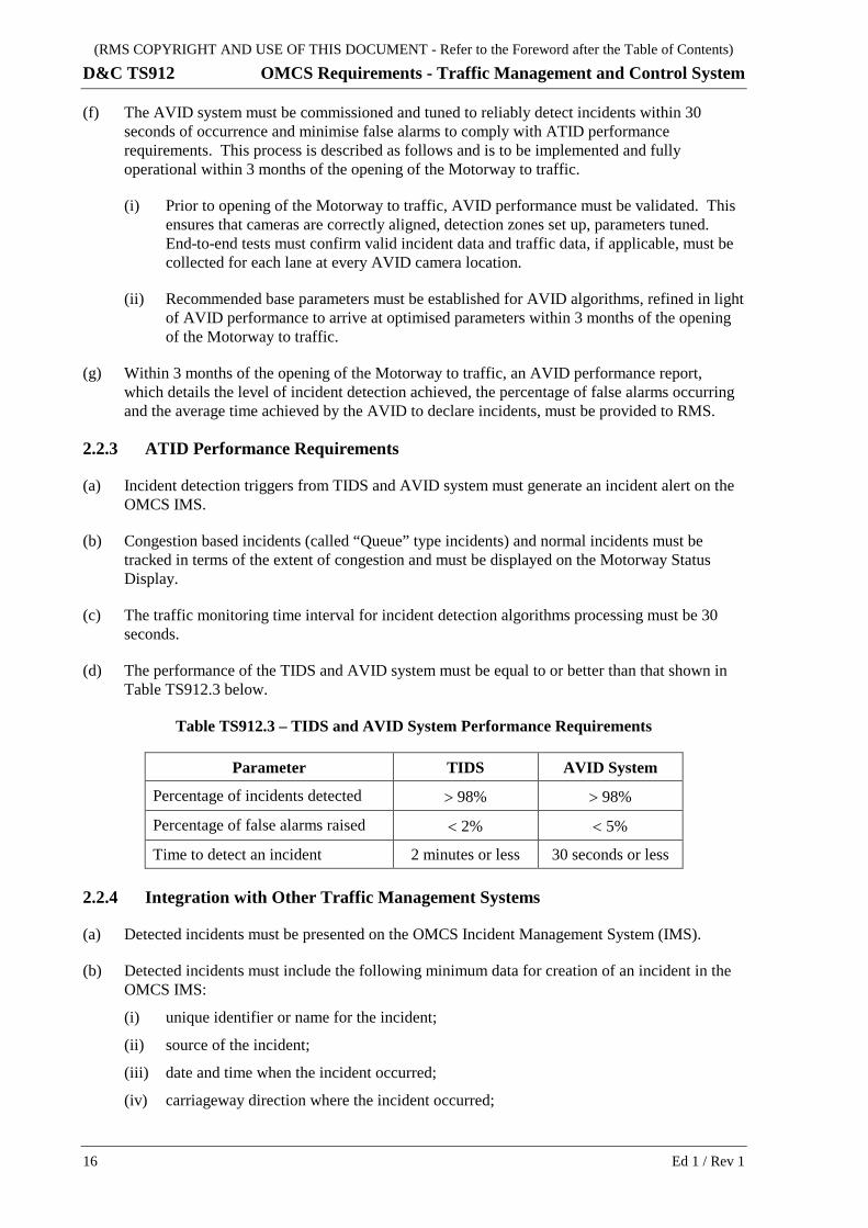
(f) The AVID system must be commissioned and tuned to reliably detect incidents within 30 seconds of occurrence and minimise false alarms to comply with ATID performance requirements. This process is described as follows and is to be implemented and fully operational within 3 months of the opening of the Motorway to traffic.
(i) Prior to opening of the Motorway to traffic, AVID performance must be validated. This ensures that cameras are correctly aligned, detection zones set up, parameters tuned. End-to-end tests must confirm valid incident data and traffic data, if applicable, must be collected for each lane at every AVID camera location.
(ii) Recommended base parameters must be established for AVID algorithms, refined in light of AVID performance to arrive at optimised parameters within 3 months of the opening of the Motorway to traffic.
(g) Within 3 months of the opening of the Motorway to traffic, an AVID performance report, which details the level of incident detection achieved, the percentage of false alarms occurring and the average time achieved by the AVID to declare incidents, must be provided to RMS.
2.2.3 ATID Performance Requirements
(a) Incident detection triggers from TIDS and AVID system must generate an incident alert on the OMCS IMS.
(b) Congestion based incidents (called “Queue” type incidents) and normal incidents must be tracked in terms of the extent of congestion and must be displayed on the Motorway Status Display.
(c) The traffic monitoring time interval for incident detection algorithms processing must be 30 seconds.
(d) The performance of the TIDS and AVID system must be equal to or better than that shown in Table TS912.3 below.
Table TS912.3 – TIDS and AVID System Performance Requirements
Parameter TIDS AVID System
Percentage of incidents detected > 98% > 98%
Percentage of false alarms raised < 2% < 5%
Time to detect an incident 2 minutes or less 30 seconds or less
2.2.4 Integration with Other Traffic Management Systems
(a) Detected incidents must be presented on the OMCS Incident Management System (IMS).
(b) Detected incidents must include the following minimum data for creation of an incident in the OMCS IMS:
(i) unique identifier or name for the incident;
(ii) source of the incident;
(iii) date and time when the incident occurred;
(iv) carriageway direction where the incident occurred;
16 Ed 1 / Rev 1

(RMS COPYRIGHT AND USE OF THIS DOCUMENT - Refer to the Foreword after the Table of Contents)
OMCS Requirements - Traffic Management and Control System D&C TS912
(v) location where the incident occurred;
(vi) identification of the lane(s) where the incident occurred.
2.3 CLOSED CIRCUIT TELEVISION (CCTV) SYSTEM REQUIREMENTS
2.3.1 General
(a) A colour CCTV system must be designed and installed to provide full coverage of the Motorway, including all carriageways, ramps, approaches and intersecting local roads in accordance with RMS Smart Motorway Design Guidelines.
(b) The CCTV system must consist of a Digital Video Control System (VCS) installed at the MCC and DRS, and at CCTV camera sites with digital IP CCTV cameras (both PTZ and fixed).
(c) The Motorway Digital VCS must be integrated with the TfNSW TMC Video Control System (Genetec Security Centre).
(d) The CCTV system must be interconnected via the MNCS to provide data communications between the VCS and the CCTV camera sites.
(e) The CCTV system must be configured on the MNCS such that any single point of failure on the PTZ or fixed camera network does not lead to any loss in CCTV coverage of the Motorway.
(f) The CCTV system must comply with Specification RMS TSI-SP-006-TMC.
2.3.2 Views and Coverage
(a) Motorway approaches must be viewable from the Motorway CCTV cameras. Motorway approaches include carriageways within 1 km of the Motorway.
(b) Intersecting roads must be viewable from the Motorway CCTV cameras for a minimum distance of 200 m from any Motorway entry ramp or exit ramp. For the purpose of this Clause, intersecting roads are defined as roads intersecting any Motorway entry ramps or exit ramp.
(c) With camera lenses at the maximum zoom setting, the CCTV system must comply with the following requirements:
(i) The views displayed must be of sufficient clarity to enable the Motorway operators to discern all vehicles within the viewable range, to categorise the vehicles by body type as motorbikes, sedans, hatchbacks, station wagons, panel vans, light commercial vehicles or trucks of all sizes and identify the vehicle registration details.
(ii) The views displayed must enable the Motorway operator to clearly discern the carriageway lane delineators, the carriageway edge line marking, local static signposting and pedestrians at the side of the carriageways.
(iii) The Motorway operators must be able to positively identify, using only the CCTV system, the Motorway segment within the Motorway in which an incident has occurred. Motorway segment identification must be aided by segment identifier data being displayed through text insertion on MCC monitors or the video wall.
(iv) All Motorist Emergency Telephone locations and motorists using the telephones must be observable using the CCTV system. The VCS must automatically switch (including any applicable PTZ/preset control) the associated CCTV camera to the METS on the METS activation.
Ed 1 / Rev 1 17

(RMS COPYRIGHT AND USE OF THIS DOCUMENT - Refer to the Foreword after the Table of Contents)
D&C TS912 OMCS Requirements - Traffic Management and Control System
(v) At the farthest point of the viewable range, the width of a medium size vehicle, as displayed on CCTV monitor, must not be less than 5.0% of the monitor screen width.
(vi) All images must be in focus within the whole of the zoom range.
(vii) The maximum distance viewable from any CCTV camera location must not be greater than 1.5 km.
(d) In addition to providing views of the Motorway, the views detailed in the SWTC must be provided by the CCTV system along the surrounding local road network.
(e) The CCTV system must also provide continuous coverage to:
(i) egress passages;
(ii) plant and equipment rooms;
(iii) entrances to Motorway service buildings ;
(iv) entrances to the MCC building;
(v) entrances to the DRS site;
(vi) high voltage (HV) equipment rooms;
(vii) any other views required for Motorway operations.
(f) The CCTV system must also provide coverage of all motorway and tunnel closure devices, including:
(i) VMS/TMS;
(ii) ISLUS/VSLS;
(iii) moveable medians;
(iv) in-pavement lights;
(v) traffic signals;
(vi) physical barriers;
(vii) advance warning signs;
(viii) changeable message signs;
(ix) ramp metering stop lines and signals.
(g) The CCTV system must provide a sufficient number of “tours” to meet Motorway operational requirements, with sufficient spare capacity to create additional “tours”.
(h) For CCTV system “tours”, cameras must be switched on each tour for a nominal 2 second period, but with the ability for the tour switching time interval to be configured by the Motorway operator.
2.3.3 Digital Video Control System (VSC) Graphical User Interface (GUI)
(a) The VCS GUI must provide Motorway operators access to minimum of 32 concurrent live video streams at full motion frame rate from any camera via the VCS server and enable camera switching.
(b) Motorway operators must be able to select and control the CCTV camera’s entire PTZ functionality from the VCS GUI and CCTV controller.
18 Ed 1 / Rev 1

(RMS COPYRIGHT AND USE OF THIS DOCUMENT - Refer to the Foreword after the Table of Contents)
OMCS Requirements - Traffic Management and Control System D&C TS912
(c) For each PTZ CCTV camera, a minimum of 32 PTZ preset positions must be selectable and configurable from the VCS GUI.
(d) The VCS GUI must enable Motorway operators to select any “tours” to start/stop and configure the tour switching time interval.
(e) The VCS GUI must be integrated with the Video Wall to allow Motorway operators to configure the CCTV displays on the Video Wall.
2.3.4 CCTV Control
(a) The TMCS must allow any CCTV camera image to be displayed on any CCTV monitor installed within the MCC and DRS.
(b) CCTV camera PTZ functions must be controlled by the Motorway operator through the CCTV Controller (console equipped with a joystick style controller) and the VCS GUI.
(c) The CCTV system must:
(i) support camera presets for all CCTV cameras, composed of position, zoom and focus;
(ii) enable the Motorway operator to create, replace and delete stored camera presets and tours;
(iii) enable the Motorway operator to search for stored camera presets and tours.
(d) The OMCS GUI must indicate when a camera is exclusively locked by another Motorway operator or TIMP.
(e) Operators at TMC must be able to remotely control and access video from any camera in the Motorway CCTV system via the TMC VCS, as detailed further in Clause 6.2.
(f) In addition to the text insertion requirement detailed in TSI-SP-006-TMC, the CCTV system must display the following text on each CCTV video image:
(i) observed Motorway segment identifier(s);
(ii) observed deluge zone(s);
(iii) nearest access/egress point upstream of the CCTV camera location.
2.3.5 Camera Locations
(a) Within all Motorway tunnel sections, fixed CCTV cameras must be installed at a maximum of 60 m intervals and view the traffic from the rear. The fixed camera can be utilised for the Automatic Video Incident Detection (AVID) system, noting that additional rear or front facing cameras may be required to satisfy AVID requirements.
(b) PTZ CCTV cameras must also be installed to provide 100% redundant coverage of the Motorway.
(c) Dedicated CCTV cameras must also be installed to provide coverage of the following:
(i) egress passages;
(ii) cross-passage doors;
(iii) crossover points;
(iv) emergency equipment cabinets;
Ed 1 / Rev 1 19

(RMS COPYRIGHT AND USE OF THIS DOCUMENT - Refer to the Foreword after the Table of Contents)
D&C TS912 OMCS Requirements - Traffic Management and Control System
(v) movable medians;
(vi) tunnel closure facilities;
(vii) breakdown/emergency stopping bay facilities.
(d) A minimum of 2 cameras must be provided at each tunnel portal to provide dedicated redundancy of CCTV coverage.
(e) The positioning and locations of CCTV cameras and deluge zones must ensure that each deluge zone within the Motorway tunnel is completely observable, using only one CCTV camera located upstream of the deluge zone.
(f) In addition, the Contractor must provide CCTV cameras, mounted on remote controlled pan-tilt heads, at the required locations detailed in the SWTC.
(g) At interchanges and interfaces with local road network, additional CCTV cameras must be provided external to the Motorway. CCTV cameras located external to the Motorway must monitor dedicated approach carriageways, intersections/interchanges with local road network and also approaches and departures on the local road network.
(h) CCTV cameras must be positioned such that they view the entire ITS infrastructure installed on the Motorway including Variable Message Signs (VMS), Tunnel Message Signs (TMS), Integrated Speed Limit and Lane Usage Signs (ISLUS), Changeable Message Signs (CMS), Advance Warning Signs (AWS), Moveable Medians (MM), In-Pavement-Lights (IPL) and Over Height Detectors (OHD).
2.3.6 CCTV Recording
(a) The CCTV system must comply with the following:
(i) simultaneously record all CCTV cameras;
(ii) playback any recorded CCTV video on the OMCS workstations;
(iii) provide secure remote access for live viewing of CCTV video via remote computers and smart phone/tablet devices for up to 20 users concurrently;
(iv) enable Motorway operators to select and export live CCTV footage from any of the video streams;
(v) allow Motorway operators to select any 2 OMCS displays to be continuously recorded as if they were a CCTV camera site at any one time;
(vi) store all CCTV recordings for a period of not less than one calendar month;
(vii) allow the Motorway operator to mark a recording segment as permanent so that it cannot be overwritten;
(viii) permanently time stamp all recordings to OMCS time;
(ix) store all recordings in 4CIF H.264 format (at 25 frames per second) or an equivalent or superior recording format which provides a superior image quality and storage life.
(b) The CCTV recording must comply with the requirements of TSI-SP-006-TMC.
2.3.7 Project Works and Temporary Works CCTV System During Construction
(a) A fully operational CCTV system must be provided during the construction of the Project Works and temporary works in accordance with the SWTC.
20 Ed 1 / Rev 1
(RMS COPYRIGHT AND USE OF THIS DOCUMENT - Refer to the Foreword after the Table of Contents)
OMCS Requirements - Traffic Management and Control System D&C TS912
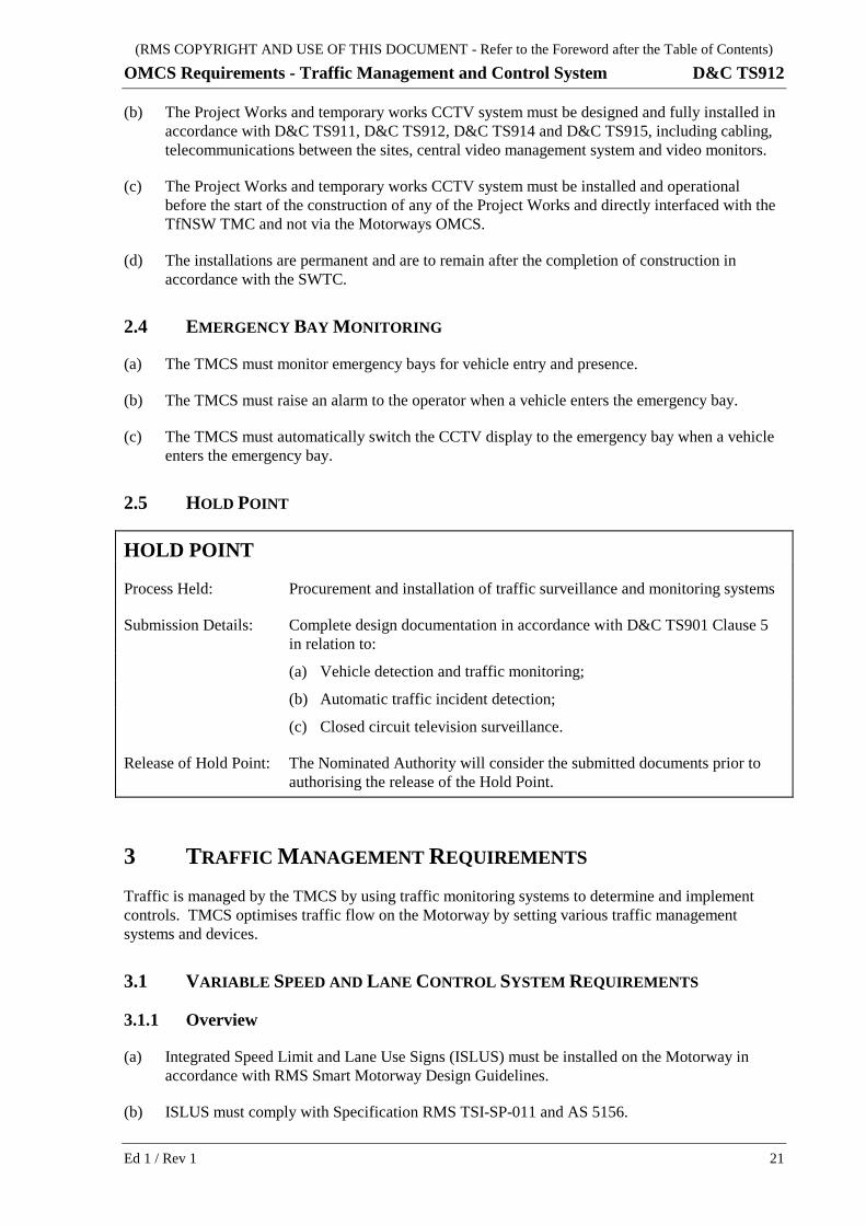
(b) The Project Works and temporary works CCTV system must be designed and fully installed in accordance with D&C TS911, D&C TS912, D&C TS914 and D&C TS915, including cabling, telecommunications between the sites, central video management system and video monitors.
(c) The Project Works and temporary works CCTV system must be installed and operational before the start of the construction of any of the Project Works and directly interfaced with the TfNSW TMC and not via the Motorways OMCS.
(d) The installations are permanent and are to remain after the completion of construction in accordance with the SWTC.
2.4 EMERGENCY BAY MONITORING
(a) The TMCS must monitor emergency bays for vehicle entry and presence.
(b) The TMCS must raise an alarm to the operator when a vehicle enters the emergency bay.
(c) The TMCS must automatically switch the CCTV display to the emergency bay when a vehicle enters the emergency bay.
2.5 HOLD POINT
HOLD POINT
Process Held: Procurement and installation of traffic surveillance and monitoring systems
Submission Details: Complete design documentation in accordance with D&C TS901 Clause 5 in relation to:
(a) Vehicle detection and traffic monitoring;
(b) Automatic traffic incident detection;
(c) Closed circuit television surveillance.
Release of Hold Point: The Nominated Authority will consider the submitted documents prior to authorising the release of the Hold Point.
3 TRAFFIC MANAGEMENT REQUIREMENTS Traffic is managed by the TMCS by using traffic monitoring systems to determine and implement controls. TMCS optimises traffic flow on the Motorway by setting various traffic management systems and devices.
3.1 VARIABLE SPEED AND LANE CONTROL SYSTEM REQUIREMENTS
3.1.1 Overview
(a) Integrated Speed Limit and Lane Use Signs (ISLUS) must be installed on the Motorway in accordance with RMS Smart Motorway Design Guidelines.
(b) ISLUS must comply with Specification RMS TSI-SP-011 and AS 5156.
Ed 1 / Rev 1 21

(RMS COPYRIGHT AND USE OF THIS DOCUMENT - Refer to the Foreword after the Table of Contents)
D&C TS912 OMCS Requirements - Traffic Management and Control System
(c) A single group controller must control the ISLUS at each location to synchronise the aspect control of the set of ISLUS, including interlocks/conflict detection.
(d) The ISLUS must incorporate:
(i) centralised control of each ISLUS from the TMCS;
(ii) ISLUS failure detection;
(iii) ISLUS conflict detection logic;
(iv) confirmation of the correct ISLUS aspect setting at all times to the TMCS;
(v) “Failure to set as expected” alerts to the TMCS;
(vi) synchronised flashing of annulus for all signs within a row and between adjacent rows.
(e) ISLUS must be installed with Military Standard screw lock IP67 plug and socket power and communications connections to facilitate maintenance replacement.
3.1.2 Operational Requirements
(a) The entire Motorway must operate as a variable speed control zone through the deployment of ISLUS and static signage along the Motorway in accordance with RMS Smart Motorway Design Guidelines.
(b) The start and end of each variable speed control zone must be signposted by a “Start Variable Speed Zone” and “End Variable Speed Zone” sign, together with a default sign to set a regulatory speed in the event of a failure of the ISLUS controls or the ISLUS are blank. Signs must comply with Drawings G6-315, G6-316 and G6-317.
(c) ISLUS must display the regulatory speed limits that are operational throughout the Motorway, including speed limit variations that are required by the TMCS in response to incidents and congestion.
(d) ISLUS must display the speed limit display with steady red annulus when the lane is open at the normal speed limit. When a reduced speed limit is applicable, the ISLUS must flash the inner part of the red annulus.
(e) ISLUS must indicate to motorists whether a lane is open (speed limit displayed), merge directions (arrow showing direction of merge), exit directions (arrow directing to exit ramp displayed), advice to leave lane as soon as safe to do so (flashing red cross displayed) or lane is closed (red cross displayed).
3.1.3 Locations
(a) Separate ISLUS must be mounted over each carriageway lane for the entire Motorway.
(b) The spacing between ISLUS must be in accordance with RMS Smart Motorway Design Guidelines, as follows:
(i) ISLUS must be located at the start of the Motorway and at each entry point;
(ii) ISLUS must be located at each Motorway interchange and positioned appropriately depending on the entry ramp merge and exit ramp diverge arrangements;
(iii) outside tunnels, the ISLUS must be located on all motorway carriageways at intervals of 500 m to 800 m, depending on the speed, roadway design and other roadside infrastructure for those sections of the Motorway;
22 Ed 1 / Rev 1
(RMS COPYRIGHT AND USE OF THIS DOCUMENT - Refer to the Foreword after the Table of Contents)
OMCS Requirements - Traffic Management and Control System D&C TS912
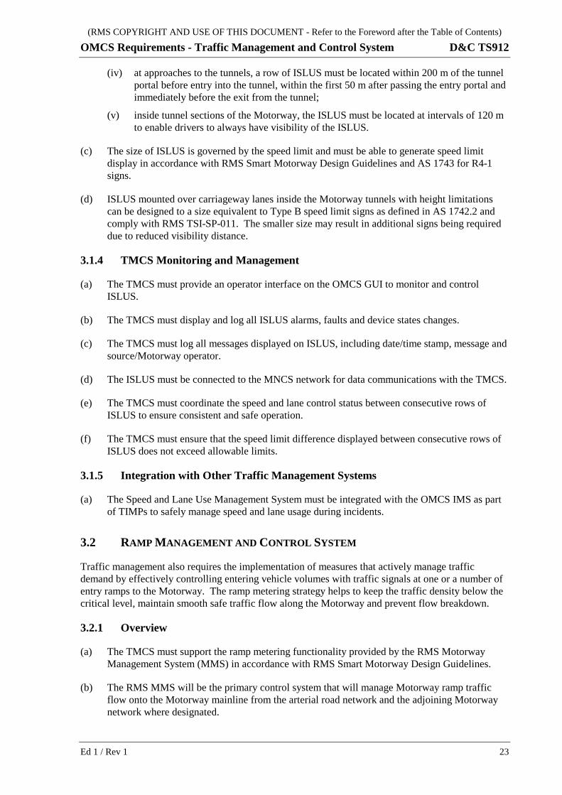
(iv) at approaches to the tunnels, a row of ISLUS must be located within 200 m of the tunnel portal before entry into the tunnel, within the first 50 m after passing the entry portal and immediately before the exit from the tunnel;
(v) inside tunnel sections of the Motorway, the ISLUS must be located at intervals of 120 m to enable drivers to always have visibility of the ISLUS.
(c) The size of ISLUS is governed by the speed limit and must be able to generate speed limit display in accordance with RMS Smart Motorway Design Guidelines and AS 1743 for R4-1 signs.
(d) ISLUS mounted over carriageway lanes inside the Motorway tunnels with height limitations can be designed to a size equivalent to Type B speed limit signs as defined in AS 1742.2 and comply with RMS TSI-SP-011. The smaller size may result in additional signs being required due to reduced visibility distance.
3.1.4 TMCS Monitoring and Management
(a) The TMCS must provide an operator interface on the OMCS GUI to monitor and control ISLUS.
(b) The TMCS must display and log all ISLUS alarms, faults and device states changes.
(c) The TMCS must log all messages displayed on ISLUS, including date/time stamp, message and source/Motorway operator.
(d) The ISLUS must be connected to the MNCS network for data communications with the TMCS.
(e) The TMCS must coordinate the speed and lane control status between consecutive rows of ISLUS to ensure consistent and safe operation.
(f) The TMCS must ensure that the speed limit difference displayed between consecutive rows of ISLUS does not exceed allowable limits.
3.1.5 Integration with Other Traffic Management Systems
(a) The Speed and Lane Use Management System must be integrated with the OMCS IMS as part of TIMPs to safely manage speed and lane usage during incidents.
3.2 RAMP MANAGEMENT AND CONTROL SYSTEM
Traffic management also requires the implementation of measures that actively manage traffic demand by effectively controlling entering vehicle volumes with traffic signals at one or a number of entry ramps to the Motorway. The ramp metering strategy helps to keep the traffic density below the critical level, maintain smooth safe traffic flow along the Motorway and prevent flow breakdown.
3.2.1 Overview
(a) The TMCS must support the ramp metering functionality provided by the RMS Motorway Management System (MMS) in accordance with RMS Smart Motorway Design Guidelines.
(b) The RMS MMS will be the primary control system that will manage Motorway ramp traffic flow onto the Motorway mainline from the arterial road network and the adjoining Motorway network where designated.
Ed 1 / Rev 1 23
(RMS COPYRIGHT AND USE OF THIS DOCUMENT - Refer to the Foreword after the Table of Contents)
D&C TS912 OMCS Requirements - Traffic Management and Control System
(c) The RMS MMS will provide ramp metering functionality that will control ramp metering signals to regulate traffic access to the Motorway mainline to optimise Motorway operation.
(d) The following devices must be installed and commissioned by the Contractor but will be controlled by the RMS MMS (and associated signal controllers) for the implementation and operation of Smart Motorway coordinated ramp metering functionality:
(i) ramp metering signal controllers and ramp signals;
(ii) traffic signal controllers and traffic signals;
(iii) SCATS detectors/loops in accordance with RMS Technical Note “Guidelines for positioning and spacing of vehicle loop detectors for a Level 3 Managed Motorway” and RMS Traffic Signal Design Manual Section 15.14 “Ramp Metering Traffic Signals”;
(vi) advance warning signs to provide regulatory information, warnings and real time information regarding the status of the ramp and associated ramp metering operations. These advance warning signs must be capable of displaying the messages of a RC1, RC2 and RC3 signs.
Advance warning signs must be controllable by ramp metering/traffic signal controllers (via local control using external switch inputs) and by RMS MMS (via remote control using Ethernet/IP);
(vii) other static signage required to support ramp metering operation including but not limited to “STOP HERE ON RED SIGNAL” (RMS Drawing R6-6) and “ONE VEHICLE ONLY PER LANE ON GREEN SIGNAL” (RMS Drawing G9-333-1);
(viii) all power, communications cabling/equipment and cabinets/housing infrastructure required for these devices, including connection to the RMS MMS.
(e) All devices to be controlled by the RMS MMS must be connected to the RMS Traffic Data Network. The connections must be in accordance with RMS Specification TS915 with the fibre termination and splicing schedules approved by the RMS Representative.
(f) The location and placement of all these devices and signs must be in accordance with the RMS Smart Motorway Design Guidelines and RMS Traffic Signal Design Manual Section 15.14 “Ramp Metering Traffic Signals”.
3.2.2 Operational Requirements
(a) The TMCS vehicle detection equipment must provide the required traffic data in real time to allow RMS MMS to monitor available capacity on the motorway and queue lengths at the entry ramps and exit ramps and use these measurements to regulate traffic entering the Motorway through the operation of traffic signals at the entry ramps, including entry ramps from adjoining Motorways.
(b) The RMS MMS will provide status of the ramp metering operations to the TMCS (or OMCS) via the C2C Interface.
(c) Without limiting the TMCS’s ability to detect incidents, the RMS MMS may provide the TMCS with status (notification or alert) on the formation and detection of queuing and congestion.
(d) The RMS MMS may request mainline speed limit changes to the TMCS (or OMCS) via the C2C Interface. In turn, the TMCS must:
24 Ed 1 / Rev 1

(RMS COPYRIGHT AND USE OF THIS DOCUMENT - Refer to the Foreword after the Table of Contents)
OMCS Requirements - Traffic Management and Control System D&C TS912
(i) set the mainline speed limits according to the RMS MMS request, subject to business rules (including priority and safety interlocks);
(ii) provide notification to the Motorway operator if the RMS MMS request is in conflict with the business rules;
(iii) provide notification to the RMS MMS if any RMS MMS request is in conflict with the business rules;
(iv) provide the ability for the Motorway operator to override any request from the RMS MMS.
(e) The TMCS must be able to request the RMS MMS to perform exit ramp flushing on appropriate exit ramps to assist with:
(i) clearing of congestion on the Motorway;
(ii) maintaining acceptable exit ramp queue lengths for safety reasons;
(iii) clearing of exit ramps where exit ramp traffic falls back onto the Motorway mainline.
(g) The TMCS must be able to request the RMS MMS to set ramp metering signage and signals to close and clear (“flush”) the selected entry ramps in response to incidents on the Motorway.
(h) The TMCS must be able to request the RMS MMS to implement complementary traffic management plans to assist with incidents on the Motorway. The RMS MMS complementary traffic management plans are complementary to TIMP implemented by the OMCS in response to incidents on the Motorway.
(i) The TMCS must be able to request the RMS MMS to clear complementary traffic management plans once the incident on the Motorway has been cleared.
(j) The TMCS must notify the Motorway operator if any request is rejected by the RMS MMS.
3.2.3 Locations
(a) The motorway vehicle detectors and SCATS detectors required for ramp metering operations must be installed in accordance with the RMS Smart Motorway Design Guidelines, RMS Technical Note “Guidelines for positioning and spacing of vehicle loop detectors for a Level 3 Managed Motorway” and RMS Traffic Signal Design Manual Section 15.14 “Ramp Metering Traffic Signals”.
(b) Advance warning signs related to ramp management and control must be located in accordance with RMS Smart Motorway Design Guidelines, including consideration of:
(i) all arterial roads feeding into the entry ramp at a position that is clear to all motorists intending to use the ramp;
(ii) each lane associated with the entry ramp to provide sufficient time for the driver to halt the vehicle at the stop line of the entry ramp.
(c) The ramp signals must be installed in accordance with RMS Traffic Signal Design Manual Section 15.14 “Ramp Metering Traffic Signals”.
(d) The stop line must be in accordance with the RMS Delineation Guideline and Specification RMS D&C R145.
(e) For underground ramp management within a Motorway tunnel section, ITS devices such as TMS, ISLUS, etc must be used to display advanced warning and management information.
Ed 1 / Rev 1 25

(RMS COPYRIGHT AND USE OF THIS DOCUMENT - Refer to the Foreword after the Table of Contents)
D&C TS912 OMCS Requirements - Traffic Management and Control System
(f) For Motorway to Motorway connections, advanced warning signs related to ramp management and control must be located in accordance with RMS Smart Motorway Design Guidelines to display advanced warning and management information.
3.2.4 TMCS Monitoring and Management
(a) The TMCS must provide an operator interface on the OMCS GUI to monitor the RMS MMS ramp metering operations on the Motorway, including:
(i) status of ramp meters;
(ii) status of ramp meters traffic signals;
(iii) status of advance warning signs.
(b) The TMCS must provide an operator interface on the OMCS GUI to monitor and manage the interface to the RMS MMS.
(c) The TMCS must display and log all RMS MMS alarms, faults and operating states.
3.2.5 Integration with Other Traffic Management Systems
The TMCS (via the OMCS) must be integrated with the RMS MMS to:
(a) provide traffic data collection and analysis systems for the RMS MMS;
(b) display the status of ramp metering operations received from the RMS MMS;
(c) provide variable speed limit control to implement speed limit changes requested by the RMS MMS;
(d) request the RMS MMS to flush entry and exit ramps in response to certain Motorway conditions;
(e) request the RMS MMS to set ramp metering signage and signals to close selected entry ramps in response to incidents on the Motorway;
(f) request the RMS MMS to implement/clear complementary traffic management plans to assist with incidents on the Motorway.
3.3 QUEUE MANAGEMENT SYSTEM
3.3.1 Overview
(a) The Queue Management System (QMS) must detect traffic congestion on the Motorway.
(b) Upon detection of traffic congestion, the QMS must automatically implement responses to safely improve the traffic flow, including but not be limited to:
(i) adjusting speed limits on ISLUS;
(ii) advising drivers via Driver Advisory Signs (e.g. VMS, TMS);
(iii) advising drivers via Radio Re-broadcast (RRB) break-in messages.
(c) In addition to any QMS response(s), the RMS MMS may provide ramp management operation in support (refer Clause 3.2).
(d) The QMS must constantly monitor the traffic congestion and adjust the traffic flow management response accordingly.
26 Ed 1 / Rev 1

(RMS COPYRIGHT AND USE OF THIS DOCUMENT - Refer to the Foreword after the Table of Contents)
OMCS Requirements - Traffic Management and Control System D&C TS912
(e) The QMS may take inputs from other TMCS systems (e.g. Traffic Monitoring and ATID) as well as other external systems to effectively identify and respond to traffic congestion.
3.3.2 Operational Requirements
The QMS must be able to:
(a) automatically detect queues and track congestion, continually updating the location, extent and severity of the congestion;
(b) respond to congestion incidents with predefined driver advisory messages on VMS, TMS and RRB break-in. The response must include VMS on the approach to the congestion location, on both the upstream Motorway mainline and intersecting roads within a configurable distance from the tail of the congestion. The messages to be employed must be developed with, and approved by the RMS and TMC;
(c) respond to congestion incidents with predefined ISLUS speed limits on approach to the congestion and for traffic within the congestion. The settings must be developed with, and approved by the RMS and TMC;
(d) alter the VMS, TMS, RRB and ISLUS response to suit the changes in location and extent of the congestion;
(e) automatically remove all VMS, TMS, RRB and ISLUS responses when the TMCS clears an incident;
(f) provide a manual override for any of these response functions to enable an operator to both deploy and remove any of the responses.
3.3.3 TMCS Monitoring and Management
(a) The TMCS must provide an operator interface at the OMCS GUI with:
(i) functions to monitor, control and manage QMS systems and devices;
(ii) a graphical representation on the Motorway Status Display of the location, extent and severity of congestion.
(b) The TMCS must display and log all QMS alerts, faults and device states.
(c) The TMCS must provide functions to configure QMS algorithms and decision logic in determining queue levels and the thresholds for operation of QMS roadside devices.
(d) The TMCS must only allow authorised personnel to have access to QMS configuration functions, including:
(i) setting of queue levels and thresholds;
(ii) settings for QMS roadside device operations.
3.3.4 Integration with Other Traffic Management Systems
The QMS must be integrated with:
(a) other traffic monitoring systems to avoid unnecessary duplication of devices and systems with similar or related functions;
Ed 1 / Rev 1 27

(RMS COPYRIGHT AND USE OF THIS DOCUMENT - Refer to the Foreword after the Table of Contents)
D&C TS912 OMCS Requirements - Traffic Management and Control System
(b) the OMCS IMS to record all congestion incidents, including records of:
(i) date and time the congestion started and finished;
(ii) location, extent and severity of the congestion;
(iii) all traffic flow management responses implemented (with time stamp);
(iv) all Motorway operator actions with the QMS.
3.4 OVER HEIGHT DETECTION AND RESPONSE SYSTEM
3.4.1 Overview
(a) The TMCS must provide an over height vehicle detection and response system in accordance with RMS Smart Motorway Design Guidelines.
(b) Vehicles higher than the specified Motorway tunnel traffic envelope must be:
(i) warned of the need to divert, and the alternative route definition provided, by means of advance fixed warning signs. The Motorway tunnel entry portals must be appropriately signposted in accordance with AS 1742.2;
(ii) provided with safe lane guidance and speed management to the alternative route via ISLUS displays;
(iii) automatically detected and warned against entering Motorway tunnels;
(iv) physically prevented from entering the Motorway tunnels. Prevention devices must be set at levels no lower than the height limit above the road surface.
(c) Automatic responses to over height vehicle detection must be generated and implemented in a timely manner to ensure that roadside devices are activated and produce safe effective advice to over height vehicle drivers and other vehicles on the Motorway.
3.4.2 Over Height Detection
(a) Over height detectors must be provided with at least two stage detection at suitable locations for each approach to detect over height vehicles before their entry to any of the Motorway tunnels.
(b) Over height detectors must be positioned before the final diversion to the tunnel and immediately after the final diversion where:
(i) the first detector must trigger a warning to the over height vehicle to divert;
(ii) the second detector must trigger a tunnel closure to prevent entry into the tunnel.
(c) The Motorway operators must be warned of all over height vehicle detected by alarms and CCTV displays automatically switching to the over height vehicle.
(d) The over height detector system must utilise modulated light beams to detect over height vehicles, or other technology with better performance.
(e) Vehicle presence detection must be provided at the detection point, using inductive loops or other acceptable vehicle detectors.
(f) The outputs from both of the detectors must be combined to identify the over height vehicle detection event.
28 Ed 1 / Rev 1

(RMS COPYRIGHT AND USE OF THIS DOCUMENT - Refer to the Foreword after the Table of Contents)
OMCS Requirements - Traffic Management and Control System D&C TS912
3.4.3 Over Height Warnings
(a) High visual impact warning signs dedicated to advising drivers of vehicles that they have been detected as over height must be erected at suitable locations at all approaches to Motorway tunnels to give the drivers adequate space to stop before entering the tunnels and opportunities to detour by alternative routes.
(b) The warning signs must advise drivers of over height vehicles not to enter the tunnels and to detour via alternative routes.
(c) Conspicuity roundels on the warning signs must be activated when an over height vehicle is detected.
(d) Red/amber/green traffic signals located at boom gates must signal “red”/“stop” when the second detector has been triggered.
(e) Physical over height barriers must be erected at the approaches to all tunnel portals to:
(i) impact on the over height sections of over height vehicles;
(ii) prevent damage to the Motorway tunnel structures.
3.4.4 TMCS Monitoring and Management
(a) The over height detection system must initiate and place an appropriate message on the VMS at approaches and portal entrances.
(b) VMS located immediately downstream of over height detectors must be directly activated during the over height detection event.
3.4.5 Integration with Other Traffic Management Systems
(a) Over height detection must raise an alarm in the OMCS IMS for the Motorway operators to manage the over height vehicle incident.
(b) All over height vehicle incidents that are detected must be logged in detail in the OMCS IMS, including:
(i) date and time of the over height vehicle detection;
(ii) location of the over height vehicle detection;
(iii) all automated responses to manage the over height vehicle detection (with time stamp);
(iv) any other Motorway operator actions to manage the over height vehicle detection.
3.5 MOTORWAY CLOSURE SYSTEM
3.5.1 Overview
(a) The TMCS must include a Motorway Closure System, in accordance with RMS Smart Motorway Design Guidelines, which provides for the automatic closure and subsequent opening of the Motorway carriageways using sequenced and automatically controlled infrastructure and operations and which:
(i) stops and diverts traffic at suitable locations in advance of the Motorway, using movable medians and in-pavement lights;
Ed 1 / Rev 1 29

(RMS COPYRIGHT AND USE OF THIS DOCUMENT - Refer to the Foreword after the Table of Contents)
D&C TS912 OMCS Requirements - Traffic Management and Control System
(ii) alerts approaching motorists of the stops, diversions and changed conditions ahead;
(iii) closes one or all carriageway lanes approaching the Motorway;
(iv) incorporates lane guidance and delineation devices that are activated when a carriageway is closed to divert traffic from the normal lane configurations, including movable medians, CMS and in-pavement lighting to delineate the altered lane configurations and to guide motorists out of the carriageway lanes;
(v) incorporates driver advisory devices and other devices or systems to accommodate automated Motorway closures, including traffic signals immediately in advance of diverge points and advanced warning signs, with conspicuity flashers, advising motorists that the traffic signals ahead are set to “red” and to “prepare to stop”;
(vi) incorporates functions to request entry ramps to be closed or opened by the RMS MMS (where applicable);
(vii) is operated by the Motorway operator via the OMCS GUI;
(viii) opens the closed carriageway lanes in the reverse sequences to the closing sequences.
(b) The automatic closure and opening of the Motorway carriageways must be controlled by the TMCS that integrates and sequences all of the infrastructure and other operations, including the ramps controlled by RMS MMS (where applicable).
(c) The TMCS must operate to achieve full or partial Motorway closure of either direction by automatic control of the closure devices and related driver advisory systems within 60 seconds of the Motorway operator ordering the closure on the OMCS GUI screen or operation of the carriageway emergency close buttons.
(d) The TMCS must provide the Motorway operator with the option to abort the tunnel closure. This option must be configurable in terms of whether it is enabled/disabled and how the abort is implemented for the various scenarios such as automatic closure due to over height vehicle.
(e) Carriageway emergency close buttons must be provided on the Motorway operator workstation desks for each carriageway of the Motorway to initiate automatic closure of the Motorway carriageway.
(f) Each carriageway emergency close button must be shrouded with a protective hinged cover flap to prevent unintentional operation.
(g) The carriageway emergency close buttons must be clearly labelled and appropriately positioned to minimise the possibility of unintentional closure of the wrong Motorway carriageway.
(h) The carriageway emergency close button must illuminate when the TMCS commences the programmed closure routine (as defined in the corresponding TIMP).
(i) When the carriageway emergency close button is activated, the OMCS IMS must implement the corresponding TIMP for automatic, safe and orderly closure of Motorway carriageway, including setting:
(i) closure traffic signals;
(ii) changeable message signs;
(iii) driver advisory signs;
(iv) physical barriers;
(v) in-pavement lighting;
30 Ed 1 / Rev 1

(RMS COPYRIGHT AND USE OF THIS DOCUMENT - Refer to the Foreword after the Table of Contents)
OMCS Requirements - Traffic Management and Control System D&C TS912
(vi) ISLUS;
(vii) ramp closures to be performed by the RMS MMS (where applicable).
(j) Deployment of physical barriers will require specific Operator confirmation before being safely deployed.
(k) The OMCS IMS must provide a “clearing” function to return the closed carriageway to the open condition from the emergency closed state.
(l) Carriageway emergency closure equipment must have individual local controls which must override remote control from the Motorway operator using OMCS.
(m) Motorway closure traffic devices such as movable medians, associated CMS, and other carriageway emergency closure equipment must be configured as multi-state devices.
3.5.2 Physical Barriers at Motorway Entry Points
(a) Physical barriers must be installed to prevent traffic from entering a tunnel section of the Motorway entry points.
(b) Physical barriers must be used in conjunction with other devices, including but not limited to ISLUS, VMS, TMS, CMS, traffic lights and IPL to achieve orderly and safe diversion of traffic away from the Motorway.
(c) The physical barriers must be able to be operated as part of an automated closure sequence (with Motorway operator confirmation before deployment) and manually by a Motorway operator through the OMCS GUI.
(d) As a minimum, physical barrier must incorporate a vertically lowered boom gate or equivalent (e.g. swing gate) and a red/amber/green traffic aspect signal mounted at the stop line in advance of the boom gate above each of the lanes closed by the boom gates.
(e) The vertically lowered boom gate must:
(i) be installed at right angles to the traffic flow at a maximum distance of 2 m between pairs of boom gates;
(ii) incorporate panelled sections that extend from the boom gate arms to road surfaces when the gates are closed;
(iii) be fitted with high visual impact red flasher lanterns that are activated immediately when the boom gate arms have started to move to their lane closure positions;
(iv) incorporate breakaway of the boom gate arms at vehicle impact speeds of greater than 10 kph or bend and distort at lower speed impacts;
(v) incorporate stop lines painted on each carriageway lane at each boom gate position.
(f) The red/amber/green traffic aspect signals must be mounted and operated as follows:
(i) Each set of the signals must be housed in a single mounting enclosure, conforming to AS 2144 and have 300 mm diameter aspects. Each set of signals must consist of two red aspects in a single enclosure.
(ii) The red/amber/green traffic aspect signals must be controlled to sequence the stopping of the traffic in accordance with normal timing practice for such events. This may include: • signals are normally off.
Ed 1 / Rev 1 31

(RMS COPYRIGHT AND USE OF THIS DOCUMENT - Refer to the Foreword after the Table of Contents)
D&C TS912 OMCS Requirements - Traffic Management and Control System
• when closing a lane, the amber aspect is turned on for 6 seconds and then the red aspect is turned on continuously.
• when reopening a lane, the red aspect is turned off and the green aspect is turned on for 60 seconds, then all aspects are turned off.
3.5.3 In-pavement Lighting (IPL)
(a) IPL must be installed to provide lane guidance to motorists of carriageway closure.
(b) IPL must be activated whenever a Motorway carriageway is closed.
(c) IPL must be of a similar standard of design and performance as airport in-pavement lights with:
(i) bright amber coloured lens;
(ii) luminous output intensity of not less than 50,000 Cd/m2;
(iii) aspect window apertures positioned to prevent them from being obscured by the build-up and accumulation of road debris.
(d) Lamp failure for in-pavement lighting must be automatically detected by the TMCS and alerted to Motorway operators via the OMCS GUI.
(e) LED based IPL is recommended to minimise maintenance access.
3.5.4 Movable Medians
(a) The TMCS must include an arrangement of movable medians to support full or partial Motorway closures.
(b) Movable median devices must be designed, manufactured and installed to provide control over the use of traffic lanes.
(c) The dimensions of movable medians must be suitable for the traffic merge required to divert traffic from the lane and must approximate a typical traffic median.
(d) Means must be provided to ensure that the movable median travels within its design travel limits and is prevented from travelling beyond these limits.
(e) The movable median must reach its destination position in less than 12 seconds, for travel across one carriageway lane or 24 seconds for travel across more than one carriageway lane.
(f) The sides of the movable median facing oncoming traffic must have conspicuity flasher lights or raised retroreflective marker panels to alert oncoming drivers of the position of the movable median.
(g) Control of the movable median must be provided by the TMCS through the OMCS GUI, including:
(i) A graphical display overlaid on the Motorway roadway schematic must provide the Motorway operator with a clear and unambiguous view and the option to move the median from its present position to a new position.
(ii) Confirmation must be received from the Motorway operator before the TMCS orders the movable median to be moved to a new position.
32 Ed 1 / Rev 1

(RMS COPYRIGHT AND USE OF THIS DOCUMENT - Refer to the Foreword after the Table of Contents)
OMCS Requirements - Traffic Management and Control System D&C TS912
(iii) The OMCS GUI must show the movable median in the transition state as distinct from any parked states.
(iv) If a movable median is moved from its designated park position by external forces, the OMCS GUI must alert the Motorway operator, who must be able to restore the movable median to its position by the use of jog controls provided on the OMCS GUI.
(v) The OMCS GUI must provide a crash stop control button on the OMCS GUI which, when operated, stops the movable median within 300 milliseconds of the crash stop being ordered by the Motorway operator.
(h) The movable median control system must be safely interlocked with other Motorway devices, including CMS and VMS, to advise motorists of the merge requirements ahead.
(i) Movable medians must be of robust design, capable of absorbing impacts from vehicle tyres at speed and provide reliable and durable service.
(j) Movable medians must include provisions to accommodate and allow for manual movement in the event of drive mechanism failure.
3.5.5 Stop Traffic Signals
(a) Traffic control signals must be installed and located in advance of diverge points to halt approaching traffic and to enable the safe deployment of diversion infrastructure, including movable medians and boom gates.
(b) Traffic control signals must be mounted above each lane to be halted and must only have 300 mm diameter aspects that conform to AS/NZS 2144.
(c) The red/amber/green traffic aspect signals must be controlled to sequence the stopping of traffic in accordance with normal timing practice for such events.
(d) A white stop line must be provided on the carriageway surface at traffic control signals in accordance with the RMS Delineation Guideline and Specification RMS D&C R145.
(e) A static sign with corner mounted warning flashers must be installed 200 m in advance of the tunnel closure traffic control signals to advise motorists when they are activated and to prepare to stop ahead.
(f) The corner mounted warning flashers must be amber coloured signals of minimum size 150 mm.
(g) The advance warning sign must be energised by the traffic control signal controller and must have a flash rate that complies with traffic signal practice and is synchronised with traffic control signal aspects.
3.5.6 Changeable Message Signs (CMS) for Movable Medians
(a) At distances of approximately 100 m to 200 m in advance of movable medians or other carriageway lane changing configuration devices, CMS must be installed to display the changed lane configuration to oncoming motorists whenever the movable medians have been moved from their normal or detente positions.
(Normal or detente position is the position of the movable median where the lane is operating in its normal configuration and the movable median has not been moved to control or divert traffic.)
Ed 1 / Rev 1 33
(RMS COPYRIGHT AND USE OF THIS DOCUMENT - Refer to the Foreword after the Table of Contents)
D&C TS912 OMCS Requirements - Traffic Management and Control System
(b) CMS must provide an unambiguous graphical representation of the approaching lane configuration change to inform motorists fully of the approaching lane merging and/or diversion manoeuvres. CMS must comply with AS 1743 Fig A1 in relation to sign dimensions.
(c) CMS must comply with:
(i) TSI-SP-034 for Prismatic or “Trivision” style CMS;
(ii) TSI-SP-067 for Electronic style CMS.
(d) CMS must have a matt/non reflective black background with white or amber graphic symbols. Dimming controls must be provided to automatically adjust the luminous output intensity from full day light to night-time ambient light conditions.
(e) Flashing conspicuity lamps must be provided in all the corners of the CMS, which must operate when the movable medians are about to change locations and until they return to their normal positions.
(f) In the normal or detente state, the CMS display must be blanked after 60 minutes following return to normal condition.
(g) CMS control must be interlocked electrically with the movable median control systems for failsafe operation to prevent any dangerous situations from occurring.
(h) CMS control systems must include monitoring for any fault and raising of corresponding alerts to Motorway operators via the OMCS GUI.
3.5.7 Physical Barriers Within Tunnels
(a) The TMCS must provide for the automatic closure and subsequent opening of the tunnel sections using sequenced and automatically controlled infrastructure and operations that stops and diverts traffic at suitable locations within the tunnels, and as a minimum at traffic bifurcations, as specified in the Project Deed.
(b) Physical barriers must be installed at the specified locations within tunnels to prevent traffic from entering a section of tunnel where an incident requires it to be closed, and in conjunction with ISLUS, TMS and RRB, to achieve an orderly diversion of traffic away from the closed section of tunnel.
(c) Physical barriers are required to provide a capability to close each of the tunnel sections downstream of the diverge point.
(d) Physical barriers must comply with the requirements of Clause 3.5.2 (c) to (f).
3.6 DANGEROUS GOODS CARRYING VEHICLES AND SMOKEY VEHICLES
3.6.1 Dangerous Goods Carrying Vehicles
(a) Vehicles carrying dangerous goods defined by the Dangerous Goods (Road and Rail Transport) Act 2008 (NSW), Dangerous Goods (Road and Rail Transport) Regulation 2014 (NSW) and the Australian Dangerous Goods Code, must be warned of the need to divert, and the alternative route definition provided, by means of advanced fixed warning signs.
34 Ed 1 / Rev 1

(RMS COPYRIGHT AND USE OF THIS DOCUMENT - Refer to the Foreword after the Table of Contents)
OMCS Requirements - Traffic Management and Control System D&C TS912
3.6.2 Smokey Vehicles
(a) A smokey vehicle camera system capable of reliably detecting, identifying and recording the entry of smokey vehicles into the Motorway tunnels must be provided by the Contractor to deter smokey vehicles from entering the Motorway tunnels.
(b) The smokey vehicle camera system must:
(i) be capable of detecting, identifying and recording smokey vehicles in tunnels;
(ii) have at least 20 second video capture of vehicle progression once smokey vehicles are detected;
(iii) comply with the “Approved Methods for the Sampling and Analysis of Air Pollutants in New South Wales” by the Department of Environment and Conservation (DEC);
(iv) perform digital image capturing of vehicle registration number plate and video recording to satisfy the requirements of TM31 as prescribed by the DEC;
(iv) identify correct lane usage for detection purposes;
(v) have a minimum of 45 days storage for potential offence file from the smokey vehicle detection system.
3.7 HOLD POINT
HOLD POINT
Process Held: Procurement and installation of traffic management systems.
Submission Details: Complete design documentation in accordance with D&C TS901 Clause 5 in relation to:
(a) Variable Speed & Lane Control System;
(b) Ramp Management and Control System;
(c) Over Height Detection and Response System;
(d) Motorway Closure System;
(e) dangerous goods carrying vehicles and smokey vehicles detection and warning system.
Release of Hold Point: The Nominated Authority will consider the submitted documents prior to authorising the release of the Hold Point.
Ed 1 / Rev 1 35

(RMS COPYRIGHT AND USE OF THIS DOCUMENT - Refer to the Foreword after the Table of Contents)
D&C TS912 OMCS Requirements - Traffic Management and Control System
4 DRIVER ADVISORY SIGNS AND TRAVELLER INFORMATION REQUIREMENTS
4.1 VARIABLE MESSAGE SIGNS (VMS)
4.1.1 Overview
(a) Colour VMS must be installed and operated to provide information messages to motorists driving on the Motorway and local roads approaching the Motorway in accordance with RMS Smart Motorway Design Guidelines.
(b) Colour VMS must comply with Specification TSI-SP-008.
4.1.2 Locations
(a) Colour VMS must be located in accordance with RMS Smart Motorway Design Guidelines and must be:
(i) sufficiently in advance of all Motorway entry and exit ramps to enable safe diversion of traffic away from incidents;
(ii) for tunnel incidents, sufficiently further upstream to divert traffic from the tunnel.
(b) In addition, the Contractor must provide Colour VMS at locations detailed in the SWTC.
(c) The type (size) of Colour VMS installed at each location must comply with RMS Smart Motorway Design Guidelines and taking into consideration the nominal speed limit at the location.
4.1.3 Operational Requirements
(a) Colour VMS must be used to advise motorists of traffic conditions that include, but are not limited to, the following:
(i) route information and alternative routes;
(ii) stopping of vehicles suspected of carrying dangerous goods;
(iii) closure of lanes on the Motorway;
(iv) closure of ramps on the Motorway;
(v) traffic congestion;
(vi) expected delays;
(vii) advisory speed;
(viii) detour requirements;
(ix) information to prevent vehicles from entering the tunnels during major incidents;
(x) information to advise drivers of over height vehicles not to enter tunnels;
(xi) travel time from the TMCS TTS and RMS Motorway Travel Time Service (MTTS);
(xii) safety messages;
(xiii) special event messages;
(xiv) ramp metering operations.
36 Ed 1 / Rev 1

(RMS COPYRIGHT AND USE OF THIS DOCUMENT - Refer to the Foreword after the Table of Contents)
OMCS Requirements - Traffic Management and Control System D&C TS912
(b) When displaying messages for incidents, VMS must operate conspicuity devices to attract driver attention.
(c) Operation of VMS must be in accordance with RMS Smart Motorway Design Guidelines, including display of:
(i) pictogram symbols in conjunction with and without text messages;
(ii) text messages with multiple colours.
4.1.4 TMCS Monitoring and Management
(a) The TMCS must provide an operator interface on the OMCS GUI to monitor and control VMS.
(b) The TMCS must display and log all VMS alarms, faults and device state changes.
(c) The TMCS must display and log all messages displayed on VMS, including date/time stamp, message and source/Motorway operator.
(d) VMS must be connected to the MNCS network for data communications with the TMCS.
4.1.5 Integration with Other Traffic Management Systems
(a) VMS must be controllable by external RMS/TMC systems via the C2C Interface, using VMS message priorities.
(b) The priority of different types of messages displayed on the VMS must be in accordance with RMS D&C TS917.
(c) VMS messages displayed as part of TIMP must use the correctly configured VMS Message priority.
4.2 TUNNEL MESSAGE SIGNS (TMS)
4.2.1 Overview
(a) TMS must be provided along the lengths of all the carriageways in tunnels in accordance with RMS Smart Motorway Design Guidelines.
(b) TMS must be a single line “Type B” VMS (200 mm character height and 18 characters long).
(c) TMS must comply with TSI-SP-008, except for dimming requirements.
(d) TMS must be able to withstand normal Motorway cleaning operations and maintain an enclosure rating of IP67.
(e) TMS must be provided with conspicuity roundels with minimum diameter of 150 mm.
(f) TMS must be installed with Military Standard IP67 screw lock plug and socket power and communications connections to facilitate maintenance swap outs.
4.2.2 Locations
(a) TMS must be located between the ISLUS signs along the length of the tunnels in such a way that drivers can always see at least one TMS at all times.
Ed 1 / Rev 1 37

(RMS COPYRIGHT AND USE OF THIS DOCUMENT - Refer to the Foreword after the Table of Contents)
D&C TS912 OMCS Requirements - Traffic Management and Control System
(b) TMS must be mounted above the carriageways in tunnel ceilings.
(c) Separation of TMS must be such that it gives an unobstructed view of the trailing TMS to motorists when within the viewing zone of both TMS.
4.2.3 Operational Requirements
(a) TMS must be used to advise motorists of traffic conditions that include, but are not limited to, the following:
(i) fire;
(ii) life safety;
(iii) incidents;
(iv) traffic information (including congestion, ramp metering operations and travel time).
(b) Where two or more TMS are set with a common message or frame, they must be synchronised for display to minimise driver distraction.
(c) Flashing of conspicuity roundels must be synchronised between adjacent and consecutive TMS.
(d) TMS on entry ramps must be able to be controlled by RMS MMS via the C2C Interface to allow them to be used as RC2 Warning Sign for ramp metering operations.
4.2.4 TMCS Monitoring and Management
(a) The TMCS must provide an operator interface on the OMCS GUI to monitor and control the TMS.
(b) The TMCS must display and log all TMS alarms, faults and device states changes.
(c) The TMCS must display and log all messages displayed on TMS, including date/time stamp, message and source/Motorway operator.
(d) TMS must be connected to the MNCS network for data communications with the TMCS.
4.2.4 Integration with Other Traffic Management Systems
(a) TMS must be integrated with the OMCS IMS as part of TIMPs to safely manage speed and lane usage during incidents.
4.3 TRAVEL TIME SYSTEM (TTS)
(a) The Travel Time System (TTS) provides travel time information for road users on the Motorway. The purpose of this system is to display travel time on VMS and TMS controlled by the TMCS. This information allows road users to make travel decisions and set expectations of the likely journey time.
(b) Operation and display of travel time information on VMS and TMS must be in accordance with RMS Smart Motorway Design Guidelines.
38 Ed 1 / Rev 1

(RMS COPYRIGHT AND USE OF THIS DOCUMENT - Refer to the Foreword after the Table of Contents)
OMCS Requirements - Traffic Management and Control System D&C TS912
4.3.1 Overview
(a) The TMCS must include the TTS, which advises drivers via Motorway VMS and TMS of the travel time to key destinations, taking into account current Motorway conditions.
(b) The TTS must calculate the travel times along the entire Motorway, to any destination, to the nearest minute.
(c) The calculation of travel time must be based on inputs from traffic monitoring and traffic management subsystems within the TMCS, which provides parameters such as regulatory speed limits and time adjustments for incidents.
(d) The TTS must also cater for the display of travel time from the RMS MTTS via the C2C Interface.
4.3.2 (Not Used)
4.3.3 Operational Requirements
4.3.3.1 Operation with Motorway VMS and TMSs
(a) All VMS and TMS controlled by the TMCS must be capable of displaying travel time information. However, under normal conditions, only nominated VMS and TMS must display travel times.
(b) VMS and TMS on the Motorway that are nominated to display travel times must be configurable.
(c) Travel time must be the default display on VMS and TMS used for the TTS.
(d) Higher priority messages must override travel time as the display on VMS and TMS.
4.3.3.2 Travel Time Messages
(a) Motorway VMS and TMS must display formatted text to indicate the travel time in minutes for up to three downstream Motorway intersections in one frame, and have the capability to report up to three destinations in another frame for the reported time.
(b) If two frames are used, the display time of each frame must be configurable in seconds, with a minimum display time of 3 seconds. For each frame, the travel time must be displayed in the following format on VMS (where TMS are limited to only one destination):
DESTINATION1 X min
DESTINATION2 Y min
DESTINATION3 Z min
Where:
(i) “DESTINATION1”, “DESTINATION2” and “DESTINATION3” are selectable destinations;
(ii) “X min”, “Y min” and “Z min” are the calculated travel times which may be coloured coded consistent with current traffic conditions in accordance with RMS Smart Motorway Design Guidelines.
Ed 1 / Rev 1 39

(RMS COPYRIGHT AND USE OF THIS DOCUMENT - Refer to the Foreword after the Table of Contents)
D&C TS912 OMCS Requirements - Traffic Management and Control System
(c) Destination text displayed on VMS and TMS must be agreed with the RMS Representative.
(d) VMS and TMS may display a travel time message together with another message (e.g. planned maintenance work) as a multi-frame/interleaved message.
4.3.3.3 TTS Destinations
(a) Destinations must include Motorway end points and any other destinations to be advised by the RMS Representative and the TMC.
(b) Selection of destinations to be displayed must be configurable from the TMCS.
(c) All VMS and TMS used to display travel time must be able to display all downstream destinations.
(d) For destinations external to the Motorway, RMS MTTS will provide relevant travel time data via the C2C Interface.
4.3.3.4 Travel Time Calculation by TTS
Travel time calculation for the TMCS must take into account:
(a) different regulatory speed limits displayed in different variable speed limit zones;
(b) impacts on travel time from incidents and congestion;
(b) if a reported travel time for a destination represents a travel speed exceeding that of the posted speed limit, then that travel time must be reported as the calculated travel time of a vehicle travelling at the speed limit.
4.3.3.5 Validation of Travel Time Calculation by TTS
(a) The Contractor must maintain and develop the TTS to ensure that calculation algorithms produce accurate results in order to maintain credibility of travel time displays.
(b) The Contractor must conduct tests and surveys to validate the travel times reported by the system and, within one month after the opening of the Motorway to traffic, the Contractor must submit a report to the RMS with these details.
4.3.3.6 Travel Time Calculation by RMS MTTS
(a) The TMCS must also take as input the travel time calculated and provided by RMS MTTS via the C2C Interface and VMS message priority queue.
(b) The RMS MTTS uses multiple system elements working together, as shown in Figure TS912.2.
40 Ed 1 / Rev 1

(RMS COPYRIGHT AND USE OF THIS DOCUMENT - Refer to the Foreword after the Table of Contents)
OMCS Requirements - Traffic Management and Control System D&C TS912
Figure TS912.2 - RMS Provided Travel Time
4.3.4 TMCS Monitoring and Management
(a) The TMCS must provide an operator interface on the OMCS GUI to monitor, control and manage TTS and associated devices.
(b) The TMCS must provide an operator interface on the OMCS GUI with a graphical TTS representation of VMS/TMS signs, destinations and travel times.
(c) The TMCS must display and log all TTS alarms, faults and device states.
(d) The TMCS must provide functions to configure TTS algorithms in determining travel times and VMS/TMS travel time message display formats.
(e) The TMCS must only allow authorised personnel to have access to TTS configuration functions.
(f) The TMCS must display and log all RMS MTTS alarms, faults and device states.
4.3.5 Integration with Other Traffic Management Systems
(a) The TTS must be integrated with the following systems to obtain input parameters affecting travel time calculations:
(i) Traffic monitoring systems;
(ii) QMS;
(iii) IMS.
(b) The TMCS must also be integrated with the RMS MTTS via the C2C Interface to allow display of RMS calculated travel times on Motorway VMS and TMS.
Ed 1 / Rev 1 41

(RMS COPYRIGHT AND USE OF THIS DOCUMENT - Refer to the Foreword after the Table of Contents)
D&C TS912 OMCS Requirements - Traffic Management and Control System
4.4 ELECTRONIC SIGNS MAINTENANCE AND DESIGN LIFE REQUIREMENTS
(a) Worker accessible gantries with walkway lighting must be installed for all VMS that are external to Motorway tunnels.
(b) All firmware/software for electronic signs must be remotely upgradable via the MNCS.
(c) The design life for all electronic signs that operate using LEDs must be not less than 10 years.
(d) Maintenance of electronic signs must be in accordance with the methodology and process specified in Specification RMS R300.
4.5 HOLD POINT
HOLD POINT
Process Held: Procurement and installation of driver advisory signs and traveller information systems.
Submission Details: Complete design documentation in accordance with D&C TS901 Clause 5 in relation to:
(a) VMS and TMS;
(b) Message priority via the C2C Interface and OMCS;
(c) TTS.
Release of Hold Point: The Nominated Authority will consider the submitted documents prior to authorising the release of the Hold Point.
5 VOICE COMMUNICATION AND RADIO RE-TRANSMISSION SYSTEMS REQUIREMENTS
(a) Voice communications and radio re-transmission systems must be provided on Motorways to service the needs and requirements of Motorway users, including emergency service organisations, the general public and Motorway Operations and Maintenance (O&M) personnel.
5.1 MOTORISTS EMERGENCY TELEPHONE SYSTEM (METS)
5.1.1 Design and Installation
(a) METS telephones must be provided in accordance with RMS Smart Motorway Design Guidelines.
(b) METS telephones must be supplied and installed by the Contractor, and must be purpose designed and built roadside telephones, and free standing. Instructions on the use of METS telephones must be provided in clearly legible signage on the METS telephones.
42 Ed 1 / Rev 1

(RMS COPYRIGHT AND USE OF THIS DOCUMENT - Refer to the Foreword after the Table of Contents)
OMCS Requirements - Traffic Management and Control System D&C TS912
(c) METS telephones must be designed to operate under extreme weather conditions likely to be experienced on the Motorway and must comply with the requirements of Specification TSI-SP-016.
(d) The METS in the tunnels must be suitable for use in a tunnel environment and must comply with the design and construction requirements for telephone communications equipment set out in AS 1670.4 and AS 4428.4.
(e) Notwithstanding the functional and operational requirements of AS 1670 and AS 4428, the METS must conform to the following functional and operational requirements:
(i) METS answering panels and control facilities must be supplied and configured at each of the Motorway operator workstations to enable each Motorway operator to independently and simultaneously answer calls from METS users on the Motorway.
(ii) METS answering panels must display current calls and queued calls on both the Motorway operator METS panel and the OMCS GUI to each Motorway operator. Additional information must also be provided to display the METS phone locations of the active callers, and queued callers, duration of the current call and waiting time for each queued call. Active and queued calls must be indicated by icon representation on the Motorway Status Display.
(iii) Upon initiation of a METS call, the respective CCTV camera must immediately zoom in to the METS location, using presets.
(iv) The METS must give confidence to METS users that the call is being progressed, prior to being answered, and if the call is queued, a confidence tone and automatic voice messages must be provided to the user.
(v) Motorway operators must be able to call any METS telephone on the Motorway from the Motorway operator METS panel.
(vi) The METS must have in-built self-test functions that are monitored by the TMCS.
(vii) The METS must be connected to the Motorway’s Electrical Power Supply and Distribution (EPSD) network and must not rely on solar panels.
5.1.2 Connection of METS Telephones
(a) METS telephones must directly call the Motorway operator upon a user lifting the handset or pushing a button.
(b) METS telephones must be located in accordance with the requirements for emergency equipment as detailed in the SWTC.
(c) METS telephones must be connected to the MCC and DRS via the optical fibre cable network of the MNCS.
5.1.3 Enclosure for METS Telephones
(a) Emergency telephones must be contained in an enclosure rated to IP65, to withstand the conditions during tunnel cleaning operations and conditions normally expected for outdoor equipment.
(b) The METS telephones must be built to withstand vandalism and to protect the sensitive components from malicious damage.
Ed 1 / Rev 1 43

(RMS COPYRIGHT AND USE OF THIS DOCUMENT - Refer to the Foreword after the Table of Contents)
D&C TS912 OMCS Requirements - Traffic Management and Control System
5.1.4 Calling Number Location Reference Data in METS
(a) The METS must provide calling number location reference data to the TMCS and the OMCS GUI. Calling number location reference data must be linked to Motorway segment identifiers, CCTV camera number and preset view reference number. The requirements for preset view operation are specified in TSI-SP-006-TMC.
5.1.5 Audible Clarity
(a) METS telephones must provide audible clarity for high ambient noise levels in the order of 95 dBA.
(b) Noise cancelling microphones and other techniques must be employed in the handsets and speakers must have sufficient output volume, with minimal distortion, and high clarity to ensure that conversation with Motorway operators is possible under all circumstances.
(c) METS telephone audible clarity performance must achieve an articulation index of 0.456 or better when subjected to objective machine based test based on ANSI S3.5-1997, with a Motorway operator at the MCC or DRS and the user in a tunnel environment, with an A-weighted background noise level for the LA10 equivalent to that given in Appendix D of Richard Heggie and Associates report ref: 10-2318 for the Westbound tube of the M5 East Motorway.
(d) METS telephones must incorporate hearing aid loop facilities in the handset for the benefit of persons with hearing disabilities.
5.1.6 Integration with Other Traffic Management Systems
(a) The METS must interface with OMCS IMS to:
(i) automatically raise an incident in OMCS IMS arising from a METS call;
(ii) locate the METS call/incident on the OMCS GUI.
(b) The TMCS must display and log all METS calls, including date/time stamp information, METS telephone ID and the Motorway operator who received or made the METS call.
(c) The TMCS must display and log all METS alarms, faults and device states.
5.2 INTERNAL OPERATIONS COMMUNICATION SYSTEM (IOCS)
(a) A Motorway Internal Operations Communication System consisting of, as a minimum, a PABX telephone system and a secure mobile voice radio network, must be provided.
(b) The PABX telephone system must provide communications between:
(i) cross and egress passages in the tunnel;
(ii) plant and equipment locations, including toll equipment locations and communications hubs;
(iii) MCC and DRS;
(iv) equipment and plant rooms;
(v) other essential areas.
44 Ed 1 / Rev 1

(RMS COPYRIGHT AND USE OF THIS DOCUMENT - Refer to the Foreword after the Table of Contents)
OMCS Requirements - Traffic Management and Control System D&C TS912
(c) The internal operations telephone communication network must be separate from the METS network.
(d) The secure mobile voice radio communication network must provide communication along the entire length of the Motorway, including:
(i) unrestricted 2-way communications at any point in the tunnel, access and ventilation tunnels, ramps and ancillary areas;
(ii) external carriageways;
(iii) along sections of adjoining motorways up to their first interchanges beyond the Motorway end points;
(iv) all roads within 2 km of the Motorway boundary.
(e) The secure mobile voice radio communication network must consist of at least 4 dedicated independently licensed UHF repeater channels, operating in half duplex (2 frequencies system) mode.
(f) The secure mobile voice radio communication network must provide adequate radio coverage (RF signal level strength of -95 dBm or better) along the entire length of the Motorway.
(g) The secure mobile voice radio communication network inside the Motorway tunnel must include a 2-way radio repeater system. This 2-way radio repeater system must be designed and installed in a manner which allows for radio maintenance activities to be undertaken without lane closure (i.e. no disruption to traffic).
(h) The secure mobile voice radio communication network must conform to the relevant requirements and standards of the Australia Communications and Media Authority (ACMA).
(i) The secure mobile voice radio communication network must be used exclusively to facilitate Motorway O&M activities.
(j) The TMCS must display and log all IOCS alarms, faults and device states.
5.3 PUBLIC ADDRESS (PA) SYSTEM
(a) Public Address (PA) functions must be provided in accordance with RMS D&C TS913.
5.4 RADIO RE-BROADCAST (RRB) AND BREAK-IN SYSTEM
5.4.1 General
(a) Radio Re-broadcast (RRB) facilities must be provided to receive and re-transmit the following radio station broadcasts to motorists in tunnels:
(i) 12 AM stations;
(ii) 12 FM stations;
(iii) all DAB+ services defined in: • 9A Sydney Multiplex (DAB+ Sydney 1); • 9B Sydney Multiplex (DAB+ Sydney 2); • 9C National Multiplex for Sydney (SY abc&SBS RADIO).
Ed 1 / Rev 1 45

(RMS COPYRIGHT AND USE OF THIS DOCUMENT - Refer to the Foreword after the Table of Contents)
D&C TS912 OMCS Requirements - Traffic Management and Control System
(b) The AM and FM radio stations that are re-broadcast must be the 12 most popular stations in each band.
(c) The RRB system must be provided with the capacity to re-broadcast at least an additional 10 AM, 10 FM radio stations and one DAB+ multiplex/ensemble in the future.
(d) For every radio station re-broadcast in a tunnel, the quality of the radio reception must be equivalent to the reception outside the tunnel. This requirement excludes radio reception disruption effects due to heterodyning caused by dual signal reception at tunnel entrance and exit transition zones.
5.4.2 RRB Infrastructure
(a) The Contractor must supply, install, commission, operate, maintain and upgrade all the equipment, plant, facilities and services required to provide RRB services (including “break-in” facility) for all of the AM, FM and DAB+ radio stations/services, including:
(i) input signal interfaces for each station/service;
(ii) signal transmission equipment for each station/service;
(iii) antenna systems to propagate radio signals in tunnels;
(iv) power supplies;
(vi) all associated cabling.
5.4.3 RRB Break-In Facility
(a) The RRB system must be equipped with a “break-in” facility that enables the TMCS to override all normal radio reception in tunnels with voice instructions for traffic management from Motorway operators during tunnel operations, emergencies and major incidents.
(b) The RRB system “break-in” facility must allow “break-in” via pre-recorded message selected by a Motorway operator from a message library and live message as spoken by a Motorway operator.
(c) The RRB system must provide a minimum number of “break-in” zones covering the entire tunnel. The zone configuration must take into consideration the tunnel roadway layout (including entry/exit ramps and any tunnel bifurcations) and safety/operational requirements.
As a minimum, the following “break-in” zones must be provided as follows:
(i) one zone for each tunnel mainline carriageway direction;
(ii) one zone for each tunnel entry ramp > 500 m in length;
(iii) one zone for each tunnel exit ramp > 500 m in length;
(iv) one zone for each tunnel segment > 500 m resulting from a bifurcation.
Any entry, exit or bifurcation segment < 500 m must be incorporated into other zones to ensure full tunnel coverage of RRB “break-in” facility.
(d) The RRB system must be configured so that the operation of break-in communications to a selected tunnel zone does not affect radio re-broadcast in any other tunnel zone and different break-ins can be operated simultaneously in different tunnel zones.
(e) The RRB break-in facility must comply with the following requirements:
46 Ed 1 / Rev 1

(RMS COPYRIGHT AND USE OF THIS DOCUMENT - Refer to the Foreword after the Table of Contents)
OMCS Requirements - Traffic Management and Control System D&C TS912
(i) Microphone and control panel equipment must be provided on every Motorway operator desk in the MCC and DRS.
(ii) The break-in facility must be able to be controlled and monitored by the TMCS via the OMCS GUI.
(iii) The Motorway operator must be able to select discreet tunnel zones for radio re-broadcast “break-in”.
(iv) A break- in tone/chime must precede all break-in messages.
(v) The break-in facility must automatically record and permanently store all live messages spoken by the Motorway operators on the TMCS.
(vi) Voice signal levels must be adjusted in the break-in facility and tested to ensure that the Motorway operators’ instructions are audible across the general range of in-vehicle radio settings.
(vii) The Motorway operator must be able to record new pre-recorded messages for inclusion in the message library.
(viii) The Motorway operator must be able to adjust the frequency (duration between repeats) of pre-recorded messages used for break-in.
(ix) The OMCS IMS must be able to automatically playback a pre-recorded message as part of a TIMP.
5.4.4 RRB Monitoring Functions
(a) The RRB system must confirm the correct operation of the radio rebroadcasts and “break-in” facility in each tunnel zone via an in-tunnel off-air monitoring system. Motorway operators must be able to select and independently monitor by listening to the AM, FM and DAB+ broadcasts in each tunnel zone.
(b) The RRB system must include facilities to enable the monitoring of system status and faults by TMCS. This must include active equipment such as transmitters, receivers, transceivers and power supplies.
(c) The RRB system must monitor the status of received and re-transmitted radio rebroadcasts for any degradation or loss of a station/service and raise alarms to the operator via the OMCS GUI.
5.4.5 TMCS Monitoring and Management
(a) The TMCS must display and log all RRB system alarms, faults and device states.
(b) The TMCS must log all usage of RRB break-in functions, including details identifying:
(i) date/time stamp information;
(ii) RRB zones used;
(iii) pre-recorded message selected by the Motorway operator;
(iv) live recording made by the Motorway operator;
(v) the Motorway operator who used RRB break-in;
(vi) the TIMP that used the RRB break-in.
Ed 1 / Rev 1 47
(RMS COPYRIGHT AND USE OF THIS DOCUMENT - Refer to the Foreword after the Table of Contents)
D&C TS912 OMCS Requirements - Traffic Management and Control System
5.5 NSW GOVERNMENT RADIO NETWORK (GRN)
5.5.1 Description of Network
(a) The NSW Government Radio Network (GRN) was established in 1993 to provide a common platform for NSW Government agencies and authorities which use mobile radio communications.
(b) Operation and maintenance of the GRN is provided by an external service provider under the oversight and assurance of the NSW Telco Authority.
5.5.2 Installation of the GRN
(a) The Contractor must accommodate the installation, operation and maintenance of the GRN on the Motorway.
(b) The NSW Telco Authority will supply, install, test, commission, operate, maintain and upgrade the GRN infrastructure, systems and services on the Motorway.
(c) The NSW Telco Authority will retain ownership of the GRN assets and will be responsible for the insurance of these assets and the repairs of any assets that are damaged.
(d) The Contractor must provide, at no cost to the NSW Telco Authority, the NSW Telco Authority with the space, access and supporting infrastructure on the Motorway to accommodate the installation, operation, maintenance and upgrading of all the GRN equipment, services, connections to external services and facilities, including, but not be limited to:
(i) rooms and associated services for GRN equipment, including lighting, ventilation, temperature control, power and ceiling and floor fit-out;
(ii) space for GRN radio transmission and receiver equipment and control system and battery cabinets for a minimum of 3 voice channels and one control channel;
(iii) antenna systems and equipment distributed throughout the Motorway tunnels for propagation of GRN transmissions and connections to transceiver equipment;
(iv) space for miscellaneous equipment, fittings and enclosures, both on the Motorway and in equipment rooms, conduits, power supplies, and cabling;
(v) integration with all related communications systems on the Motorway;
(vi) a communications link from GRN equipment on the Motorway to the GRN network operations centre that is external to the Motorway. The communications link must carry voice data, control data and alarm data for a minimum of four GRN channels.
(e) The Contractor must provide electrical power to operate the GRN system at no cost to the NSW Telco Authority.
(f) The Contractor must provide access to and support, cooperate and assist the NSW Telco Authority or its agents with the installation, testing, commissioning, operation, maintenance and upgrading of the GRN infrastructure, systems and services on the Motorway.
(g) The Contractor is responsible for payment of all capital and recurring costs and charges associated with the supply, installation, testing, commissioning, operation, maintenance and upgrading of the GRN, including the costs, charges and fees incurred and charged by the NSW Telco Authority. General information relating to the GRN can be obtained from the NSW Telco Authority website: http://telco.nsw.gov.au/.
48 Ed 1 / Rev 1

(RMS COPYRIGHT AND USE OF THIS DOCUMENT - Refer to the Foreword after the Table of Contents)
OMCS Requirements - Traffic Management and Control System D&C TS912
(h) The TMCS must display and log all GRN equipment alarms and faults.
5.6 NSW POLICE FORCE RADIO NETWORK (NSWPFRN)
5.6.1 Description of Network
(a) The NSW Police Force Operational Communications and Information Command operates and maintains the NSW Police Force Radio Network (NSWPFRN).
(b) Additional information is available from the NSW website at: http://www.police.nsw.gov.au/about_us/structure/specialist_operations/operational_communications_and_information_group
(c) The NSWPFRN operates in the 450 to 470 MHz UHF band. Future data radio channels may occupy the 380 to 420 MHz band.
(d) The following NSWPFRN radio channels must be provided throughout the Motorway:
(i) VKG Channel 10-D5 from North Sydney;
(ii) VKG Channel 11-E from Ryde;
(iii) VKG Channel 26 Special Operations Channel;
(iv) VKG Channel 46 Anti-Terrorist Channel.
(e) The Contractor must provide spare capacity for two more unspecified channels allocated to the NSWPFRN.
(f) The NSW Police Force operates portable belt type radios on the NSWPFRN and these radios must operate on all sections of the Motorway.
5.6.2 Installation of NSW Police Force Radio Network
(a) The Contractor must provide the NSW Police Force with all things necessary to accommodate, install, operate and maintain the NSWPFRN, at no cost to the NSW Police Force. These include but are not limited to:
(i) equipment rooms and associated services to and in the rooms, including lighting, ventilation, temperature control, power and ceiling and floor fit-out;
(ii) space for NSWPFRN radio transmission and receiver equipment and control system plus battery cabinets;
(iii) antenna systems and equipment distributed throughout the Motorway tunnels for propagation of NSWPFRN transmissions and connections to transceiver equipment;
(iv) space for miscellaneous equipment, fittings and enclosures both in tunnels and equipment rooms, conduits, power supplies, and cabling;
(v) integration with all related communications systems on the Motorway;
(vi) a communications link from the NSWPFRN equipment on the Motorway to the NSWPFRN network operations centre that is external to the Motorway.
(b) The Contractor must provide the electrical power infrastructure to operate the NSWPFRN system, at no cost to the NSW Police Force.
Ed 1 / Rev 1 49

(RMS COPYRIGHT AND USE OF THIS DOCUMENT - Refer to the Foreword after the Table of Contents)
D&C TS912 OMCS Requirements - Traffic Management and Control System
(c) The Contractor must provide access to and must support, cooperate, assist and liaise with the NSW Police Force when the Contractor undertakes the installation, testing, and commissioning of the NSWPFRN infrastructure, systems and services on the Motorway.
(d) The NSW Police Force will take ownership of the NSWPFRN after it is installed, tested and commissioned and will be responsible for the ongoing routine and breakdown maintenance and upgrading of the NSWPFRN.
(e) The Contractor must provide access to and must support, cooperate and assist the NSW Police Force or its agents with the maintenance and upgrading of the NSWPFRN infrastructure, systems and services on the Motorway.
(f) Specific information on the NSWPFRN channels and other detailed requirements for the NSWPFRN can be obtained from the NSW Police Force Communications Group on 02 9265 4502.
(g) The TMCS must display and log all NSWPFRN equipment alarms and faults.
5.7 MOBILE TELEPHONES AND OTHER RELATED MOBILE COMMUNICATION SERVICES
(a) The Contractor must do all things necessary to enable the installation, commissioning, operation and maintenance of all mobile telephone and all other related mobile communication services on the Motorway.
(b) Mobile telephone and other related mobile communication services must include sufficient capacity to service the number of voice and data channels required for the usage factors experienced by mobile telephone carriers for heavily traffic road corridors. Capacity requirements of the services must allow for peak loading that may occur during incidents on the Motorway.
(c) The Contractor must do all things necessary to enable it to enter into commercial agreements with all mobile telephone communication carriers for the provision of the infrastructure and services that are necessary to support the installation, operation and maintenance of the carriers’ equipment. These provisions must include:
(i) all spaces and excavations required to house the plant, equipment and services, including those required in cross passages and in tunnel niches;
(ii) equipment rooms to house all communications and computer equipment, including adequate lighting, ventilation, temperature control, electrical power and distribution, cabling access, access security and specific finishes to suit the installed equipment;
(iii) accommodation of fibre optic repeater and transceiver equipment located in tunnels;
(iv) conduits and cables to link all the elements of mobile telephones and communication services equipment;
(v) accommodation for antennas mounted internally and externally to tunnels;
(vi) an essential service power supply, including earthing arrangements as applicable for communications;
(vii) accommodation of communication trunk links to wired services or microwave links for connection to general external communications networks of the communications carriers;
(viii) restricted access to authorised personnel, controlled by the Contractor.
50 Ed 1 / Rev 1
(RMS COPYRIGHT AND USE OF THIS DOCUMENT - Refer to the Foreword after the Table of Contents)
OMCS Requirements - Traffic Management and Control System D&C TS912
(d) The Contractor must meet the requirements of the lead mobile telephone carrier and, as a minimum, provide:
(i) a Distributed Antenna System (DAS) that complies with lead mobile telephone carrier requirements and covering the entire tunnel;
(ii) a multi-carrier combiner for at least 4 carriers (or as otherwise specified by the lead mobile telephone carrier);
(iii) a system that is suitable for multi-carrier deployment across all the carriers’ operating bands;
(iv) portal antennas to provide handover coverage to and from the outdoor networks.
(e) The Contractor must provide all mobile telephone communication carriers with sufficient access to enable them to install, test, commission, operate, maintain and upgrade their equipment.
(f) The Contractor must do all things necessary to enable the operation of all mobile telephony and other related mobile communication services when the Motorway is opened for public use.
(g) The installation, operation and maintenance of mobile telephone communications equipment and services must comply with the requirements of the Environmental Documentation and the Contractor must assist and facilitate the process for acquiring the required approvals.
5.8 LOCATION SERVICES
(a) The Motorway must be provided with Location Services capability within Motorway tunnel sections.
(b) The Tunnel Location Services technology, including but not limited to Global Navigation Satellite System (GNSS) retransmission, WiFi and Bluetooth, must utilise open standards to allow multiple vendors/systems to utilise this capability.
(c) The performance and accuracy of the Tunnel Location Services must be sufficient for safe navigation and way-finding applications.
(d) As a minimum, the Tunnel Location Services must provide location accuracy to within 1 m.
(e) The Tunnel Location Services must comply with ACMA requirements and all licenses/approvals must be obtained.
(f) The TMCS must display and log all Tunnel Location Services alarms, faults and device states.
5.9 RMS UHF RADIO RE-BROADCAST SERVICE
5.9.1 Description of Network
(a) RMS operates and maintains the RMS UHF Radio Re-broadcast (RRB) Service.
(b) The RMS UHF RRB Service operates under the following frequencies:
(i) ACMA License 1976567 (Sydney Harbour Bridge): Call Sign VNK661, Base Tx 467.625 MHz, Base Rx 457.625 MHz;
Ed 1 / Rev 1 51

(RMS COPYRIGHT AND USE OF THIS DOCUMENT - Refer to the Foreword after the Table of Contents)
D&C TS912 OMCS Requirements - Traffic Management and Control System
(ii) ACMA License 1976568 (Anzac Bridge 1): Call Sign VNK662, Base Tx 469.4375 MHz, Base Rx 459.4375 MHz;
(iii) ACMA License 1976755 (Anzac Bridge 2): Call Sign VNK795, Base Tx 469.725 MHz, Base Rx 459.725 MHz;
(iv) ACMA License 1976657 (Sydney Tower): Call Sign VNK717, Base Tx 469.775 MHz, Base Rx 459.775 MHz.
5.9.2 Installation of RMS UHF RRB Service
(a) The Contractor must accommodate the installation, operation and maintenance of RMS UHF RRB Service on the Motorway.
(b) RMS will supply, install, test, commission, operate, maintain and upgrade the RMS UHF RRB Service infrastructure, systems and services on the Motorway.
(c) RMS will retain ownership of the RMS UHF RRB Service assets and will be responsible for the insurance of these assets and the repairs of any assets that are damaged.
(d) The Contractor must provide RMS UHF RRB Service with all things necessary to accommodate, install, operate and maintain the RMS UHF RRB Service, at no cost to RMS. These include, but are not limited to:
(i) equipment rooms and associated services to and in the rooms, including lighting, ventilation, temperature control, power and ceiling and floor fit-out;
(ii) space for RMS UHF RRB Service radio transmission and receiver equipment and control system plus battery cabinets;
(iii) antenna systems and equipment distributed throughout the Motorway tunnels for propagation of RMS UHF RRB Service transmissions and connections to transceiver equipment;
(iv) space for miscellaneous equipment, fittings and enclosures, both in the tunnels and in equipment rooms, conduits, power supplies, and cables;
(v) integration with all related communications systems on the Motorway;
(vi) a communications link from the RMS UHF RRB Service equipment on the Motorway to the RMS UHF RRB Service network operations centre that is external to the Motorway.
(e) The Contractor must provide the necessary electrical power infrastructure to operate the RMS UHF RRB Service, at no cost to the RMS.
(f) The Contractor must provide access to and must support, cooperate and assist the RMS or its agents with the maintenance and upgrading of the RMS UHF RRB Service infrastructure, systems and services on the Motorway.
(g) The TMCS must display and log all RMS UHF RRB Service equipment alarms and faults.
52 Ed 1 / Rev 1

(RMS COPYRIGHT AND USE OF THIS DOCUMENT - Refer to the Foreword after the Table of Contents)
OMCS Requirements - Traffic Management and Control System D&C TS912
5.10 HOLD POINT
HOLD POINT
Process Held: Procurement and installation of voice communication and radio re-transmission systems.
Submission Details: Complete design documentation in accordance with D&C TS901 Clause 5 in relation to:
(a) Motorway emergency telephone system; (b) Internal operations communication system; (c) Public Address system; (d) Radio Re-broadcast and break-in system; (e) NSW Government Radio Network and Mobile Data Radio Network; (f) NSW Police Force radio network (g) Other mobile telecommunications carrier systems; (h) Global Navigation Satellite System; (i) RMS UHF Radio Re-broadcast Service.
Release of Hold Point: The Nominated Authority will consider the submitted documents prior to authorising the release of the Hold Point.
6 INTERFACE REQUIREMENTS WITH RMS AND TFNSW TMC
6.1 CENTRE-TO-CENTRE (C2C) INTERFACE
6.1.1 General
(a) Centre to Centre (C2C) Interface must be designed, constructed, installed, commissioned, operated and maintained as part of the TMCS to:
(i) exchange traffic and traffic management data between the RMS, other agreed OMCSs and the OMCS;
(ii) facilitate the coordination of incidents on the Motorway with the RMS and other agreed OMCSs;
(iii) provide remote monitoring of traffic systems and traffic movements on the Motorway, including approach roads and ramps to RMS controlled sections;
(iv) provide shared, priority control of Motorway traffic devices to RMS as agreed.
(b) The TMCS must be configured to receive and process incident and device messages sent from RMS or another Motorway OMCS over the C2C Interface.
(c) The services to be provided as part of the C2C interface between the Contractor and the RMS are detailed in RMS D&C TS917.
(d) The Contractor must provide all engineering services to support RMS in the design, installation, testing and commissioning of the end-to-end C2C Interface.
Ed 1 / Rev 1 53

(RMS COPYRIGHT AND USE OF THIS DOCUMENT - Refer to the Foreword after the Table of Contents)
D&C TS912 OMCS Requirements - Traffic Management and Control System
6.1.2 Data Communications Protocol for the C2C Interface
The Data Communications Protocol between the TMCS and RMS must conform to the following:
(a) The interface must utilise a non-proprietary, industry standard extensible message structure protocol (XML) and data transportation mechanisms delivering XML over Ethernet (HTTPS).
(b) The data communications protocol between the OMCS and RMS must conform to the requirements and message set definitions for C2C Interfaces published by transportation authorities, as per NTCIP 2306 and ITE/AASHTO TMDD Standard and IEEE 1512 and their corresponding XML schemas.
(c) The interface data object definitions and the required messages interchange criteria and rules must conform to RMS D&C TS917.
(d) All aspects of the protocols in the respective TMCS and RMS systems must be implemented and the protocol functionality must be supported in the TMCS.
(e) The interface must be capable of providing authentication services via X509 Binary Security Token and WS-Security Username Token in accordance with Oasis 200401 and RMS A3410742 Security Implementation Guide.
6.1.3 Requirements to Implement Data Communications Protocol
(a) The implementation of the data communications protocol between the TMCS and the RMS will result in the integration of the Motorway into the Sydney Road Network IMS operating in the TMC.
(b) Suitably qualified and experienced technical support personnel must be deployed to ensure that the requirements for implementation of the data communications protocol are understood and that the design and architecture of the TMCS are harmonised with the data communication protocol application.
6.1.4 Testing and Commissioning of the Data Communications Protocol
(a) The testing, commissioning and acceptance of the data communications protocol must be completed concurrently with the commissioning of the TMCS and prior to the opening of the Motorway to traffic.
(b) Scheduling of testing activity must be agreed with the RMS and TfNSW TMC to ensure successful end-to-end testing.
(c) C2C Interface test plans and test specifications must be prepared and submitted to the RMS for approval 60 days prior to the commencement of testing.
6.2 CCTV INTERFACE
(a) TfNSW TMC must have access to all CCTV cameras installed on the Motorway.
(b) The Motorway CCTV system must be integrated with the TMC Genetec Video Management System in accordance with TSI-SP-006-TMC. To ensure compatibility, the Contractor must confirm with RMS as to the version of TMC Genetec Video Management System.
54 Ed 1 / Rev 1

(RMS COPYRIGHT AND USE OF THIS DOCUMENT - Refer to the Foreword after the Table of Contents)
OMCS Requirements - Traffic Management and Control System D&C TS912
(c) TfNSW must be able to access up to 16 CCTV cameras at full motion rate and at any one point in time.
(d) TfNSW TMC must be able to control the pan, tilt and zoom for each Motorway CCTV PTZ camera from the TMC’s video control consoles and TMC’s Genetec Video Management System.
(e) If the Motorway CCTV system is able to access the TMC CCTV video feeds, the Motorway CCTV system must comply with the TMC Policy for Using RMS Traffic Management CCTV Cameras (TMC-POL-402002).
6.3 RMS MOTORWAY MANAGEMENT SYSTEM
(a) An interface to the RMS MMS must be provided via the C2C Interface in accordance with RMS D&C TS917.
6.4 HOLD POINT
HOLD POINT
Process Held: Installation and integration with TMCS interfaces.
Submission Details: Complete design documentation in accordance with D&C TS901 Clause 5 in relation to:
(a) C2C Interface to RMS/TfNSW TMC;
(b) CCTV Interface to TfNSW TMC.
Release of Hold Point: The Nominated Authority will consider the submitted documents prior to authorising the release of the Hold Point.
7 TMCS TESTING AND COMMISSIONING
7.1 GENERAL
(a) The TMCS comprises several subsystems that must be tested both individually and when integrated with the OMCS.
(b) The testing and commissioning of the TMCS must satisfy the requirements of the overall OMCS integration and testing detailed in RMS D&C TS911.
(c) The testing and commissioning of the TMCS must also adhere to the process, methodologies and documentation requirements specified in RMS D&C TS901 Clause 5 and RMS D&C TS911 Clause 9.
Ed 1 / Rev 1 55

(RMS COPYRIGHT AND USE OF THIS DOCUMENT - Refer to the Foreword after the Table of Contents)
D&C TS912 OMCS Requirements - Traffic Management and Control System
7.2 HOLD POINT
HOLD POINT
Process Held: Commencement of testing.
Submission Details: Complete test documentation (including Test Plans and Test Specifications) in accordance with D&C TS901 Clause 5.
Release of Hold Point: The Nominated Authority will consider the submitted documents prior to authorising the release of the Hold Point.
56 Ed 1 / Rev 1

(RMS COPYRIGHT AND USE OF THIS DOCUMENT - Refer to the Foreword after the Table of Contents)
OMCS Requirements - Traffic Management and Control System D&C TS912
ANNEXURES TS912/A TO TS912/B – (NOT USED)
ANNEXURE TS912/C – SCHEDULES OF HOLD POINTS AND IDENTIFIED RECORDS
Refer to Clause 1.3.3.
C1 SCHEDULE OF HOLD POINTS
Clause Description
2.5 Procurement and installation of traffic surveillance and monitoring systems.
3.7 Procurement and installation of traffic management systems.
4.5 Procurement and installation of driver advisory signs and traveller information systems.
5.10 Procurement and installation of voice communication and radio re-transmission systems.
6.4 Installation and integration with TMCS interfaces.
7.2 Commencement of testing.
C2 SCHEDULE OF IDENTIFIED RECORDS
The records listed below are Identified Records for the purposes of RMS D&C Q6 Annexure Q/E.
Clause Description of Identified Record
Systems Engineering Management Plan, System Requirements Specification, Design Documentation, Equipment Documentation, Test Plans, Test Specifications, and Work-As-Executed Documentation for OMCS complying with Clause 5 of D&C TS901.
7 Test documentation, including test reports, for all OMCS installation, testing and commissioning activities carried out.
Ed 1 / Rev 1 57

(RMS COPYRIGHT AND USE OF THIS DOCUMENT - Refer to the Foreword after the Table of Contents)
D&C TS912 OMCS Requirements - Traffic Management and Control System
ANNEXURE TS912/D – PLANNING DOCUMENTS Refer to Clause 1.3.3.
The following documents are a summary of documents that must be included in the PROJECT QUALITY PLAN. The requirements of this Specification and others included in the Project Deed must be reviewed to determine additional documentation requirements.
Clause Description of Document
Systems Engineering Management Plan, Design/Development Plan(s) and Test Plan(s) developed in accordance with D&C TS901 and D&C TS921.
ANNEXURES TS912/E TO TS912/L – (NOT USED)
58 Ed 1 / Rev 1
(RMS COPYRIGHT AND USE OF THIS DOCUMENT - Refer to the Foreword after the Table of Contents)
OMCS Requirements - Traffic Management and Control System D&C TS912
ANNEXURE TS912/M – REFERENCED DOCUMENTS Refer to Clause 1.3.6.
RMS Specifications
D&C Q6 Quality Management System (Type 6)
D&C R145 Pavement Marking (Performance Based)
D&C TS901 OMCS Overview and General Requirements
D&C TS911 OMCS Requirements - Motorway Control Centre
D&C TS913 OMCS Requirements - Plant Management and Control System
D&C TS914 OMCS Requirements - Electrical Power Supply and Distribution System
D&C TS915 OMCS Requirements - Motorway Network Communications System
D&C TS916 OMCS Requirements - Electronic Toll Collection System
D&C TS917 OMCS Requirements - C2C Interface for Motorways
D&C TS918 OMCS Requirements - Road Tunnel and Underpass Lighting
RMS 08.092 Traffic Signal Design – Section 15 Special Situations
SI-TCS-008 Installation and Reconstruction of Traffic Light Signals
TSI-SP-006-TMC General Specification for the Design, Supply, Installation, Testing and Commissioning of Closed Circuit Television Systems for Motorways
TSI-SP-008 Specification for Variable Message Signs
TSI-SP-011 Specification for Integrated Speed Limit and Lane Use Signs
TSI-SP-016 General Requirements for Outdoor Electronic Equipment
TSI-SP-026 Communications Protocol for Vehicle Detection Systems
TSI-SP-034 Changeable Message Signs - Prismatic
TSI-SP-038 General Requirements for Vehicle Loop Detector Equipment
TSI-SP-067 Changeable Message Signs - Electronic
RMS Smart Motorway Design Guidelines
RMS Smart Motorway Guidelines
RMS Smart Motorway Supplement for Traveller Information
RMS Smart Motorway Supplement for Ramp Signals
RMS Smart Motorway Supplement for LUMS including VSL
RMS Smart Motorway Design Guide Capacity and Flow Analysis
RMS Smart Motorway Design Guide Tunnel Traffic Management
RMS Smart Motorway Design Guide Traffic Monitoring and Surveillance
RMS Technical Note: Guidelines for positioning and spacing of vehicle loop detectors for a Level 3 Managed Motorway
RMS Guidelines for Priority Vehicle Access on Entry Ramps for Managed Motorways
Ed 1 / Rev 1 59

(RMS COPYRIGHT AND USE OF THIS DOCUMENT - Refer to the Foreword after the Table of Contents)
D&C TS912 OMCS Requirements - Traffic Management and Control System
RMS Drawings
VC005-17 Installation of Stop Line Detectors
VC005-33 Installation of Loop Detectors at Traffic Detector Stations
G6-315 Start Variable Speed Limit Zone
G6-316 End Variable Speed Limit Zone
G6-317 If Variable Speed Limit Sign is Blacked Out
G9-333-1 One Vehicle Only Per Lane On Green Signal
R6-6 Stop Here On Red Signal
Australian Standards
AS 1670.4 Fire detection, warning, control and intercom systems - System design, installation and commissioning - Emergency warning and intercom systems
AS 1742.2 Manual of uniform traffic control device - Traffic control devices for general use
AS 1743 Road signs - Specifications
AS 2144 Traffic signal lantern
AS 2276 Cables for Traffic Signal Installations
AS 4428.4 Fire detection, warning, control and intercom systems - Control and indicating equipment - Emergency intercom control and indicating equipment
AS 5156 Electronic speed limit signs
Austroads Publication
AP-C87-15 Austroads Glossary of Terms
AP-T60/06 Austroads Technical Report - Automatic Vehicle Classification by Vehicle Length
EPA Publication
Approved Methods for the Sampling and Analysis of Air Pollutants in New South Wales
NSW Legislation
Dangerous Goods (Road and Rail Transport) Act NSW 2008
Dangerous Goods (Road and Rail Transport) Regulation NSW 2014
National Code
National Transport Commission Australian Dangerous Goods Code
60 Ed 1 / Rev 1

(RMS COPYRIGHT AND USE OF THIS DOCUMENT - Refer to the Foreword after the Table of Contents)
OMCS Requirements - Traffic Management and Control System D&C TS912
International Standards
ANSI S3.5-1997 Methods for Calculation of the Speech Intelligibility Index
IEEE 1512 Space Communications - Disaster Communications
NTCIP 2306 Application Profile for XML Message Encoding and Transport in ITS Center-to-Center Communications
Ed 1 / Rev 1 61


![Offsite Modular Construction System [OMCS]](https://img.pdfslide.us/doc/110x75/58819cd61a28ab1a398b46e9/offsite-modular-construction-system-omcs.jpg)