Embed Size (px)
Citation preview
DAYANANDA SAGAR COLLEGE OF ENGINEERING
(An Autonomous Institution affiliated to Visvesvaraya Technological University, Belagavi)
CHOICE BASED CREDIT SYSTEM (CBCS)
SCHEME OF TEACHING AND EXAMINATION 2015-2016
B.E. TELECOMMINICATION ENGINEERING
III SEMESTER
Sl. No.
Subject
Code
Subject Title Course Type
Teaching Department
Board Teaching Hours/Week
Examination Credits
L T P CIE SEE Total
1 MAT31 ENGINEERING MATHS-III BS Maths Maths 4 0 0 50 50 100 4
2 TE32 NETWORK ANALYSIS AND
CONTROLSYSTEMSV
TCE TCE TCE 4 0 0 50 50 100 4
3 EC33 ELECTRO MAGNATIC FIELD THEORY EC TCE EC 4 0 0 50 50 100 4
4 EC34 ANALOG ELECTRONICS CIRCUITS
(FOUNDATION)
EC TCE EC 3 0 0 50 50 100 3
5 EC35 LOGIC DESIGN EC TCE EC 3 0 0 50 50 100 3
6 TE36 PRINCIPLES OF DATA CABLING &
Networking
TCE TCE TCE 3 0 0 50 50 100 3
7 TEL37 ANALOG ELECTRONICS CIRCUITS LAB TCE TCE TCE 0 1 2 50 50 100 2
8 TEL38 LOGIC DESIGN LAB TCE TCE TCE 0 1 2 50 50 100 2
Total 400 400 800 25

ENGINEERING MATHEMATICS-III
Course code: MAT31 Credits: 04 L: P: T: S: 4:0:0: 0 CIE Marks: 50 Exam Hours:03 SEE Marks: 50
Course Objectives: 1. Generalize a periodic function as a sum of series of trigonometric functions
using Fourier series.
2. Explain the concept of Fourier and Z transform and state the use of it in
time varying signals (continuous).
3. Finding solutions of equations and also evaluating approximate areas and
volume using numerical methods.
Course Outcomes: At the end of the course, student will be able to:
Mapping of Course outcomes to Program outcomes:
PO1 PO2 PO3 PO4 PO5 PO6 PO7 PO8 PO9 PO10 PO11 PO12
CO1 3 3 1 1
CO2 3 3 2 1
CO3 3 3 1 1
CO4 3 3 2 1
CO5 3 3 2 1
CO1 Understand the use of periodic signals and Fourier series to analyze circuits
CO2 Demonstrate Fourier Transform as a tool for solving Integral equations.
CO3 Use Method of Least Square for appropriate Curves
CO4 Choose appropriate Numerical methods to solve Algebraic and Transcendental equations
CO5 Demonstrate the concept of Interpolation and Numerical Integration
CO6 Apply Z Transform to solve Difference Equation

CO6 3 3 2 1
Module Contents of the Module Hours CO’s
1
FOURIER SERIES: Periodic functions, Dirichlet’s conditions, Fourier series of periodic
functions of period 2𝜋 and with arbitrary period 2𝑙, Half-range Fourier sine and cosine series, Practical Harmonic Analysis
12 CO1
2
FOURIER TRANSFORMS: Infinite Fourier transform, Infinite Fourier sine and cosine transforms, Inverse Fourier transforms, Inverse Fourier sine and cosine transforms, Convolution theorem (without proof) and problems.
10 CO2
3
Curve fitting: Curve fitting by the method of least squares, Fitting of the curves of the form 𝑦 = 𝑎𝑥 + 𝑏, 𝑦 = 𝑎𝑥2 + 𝑏𝑥 + 𝑐, 𝑦 = 𝑎𝑒𝑏𝑥, 𝑦 =𝑎𝑥𝑏 . Numerical Methods: Numerical solution of algebraic and transcendental equations, Regula-Falsi method, Newton-Raphson method.
10 CO3,CO4
4
FINITE DIFFERENCES: Forward and Backward differences, Newton’s forward and Backward interpolation formulae. Newton’s
divided difference formula, Lagrange’s interpolation formula and
inverse interpolation formula (without proofs). Numerical Integration: Simpsons 1/3rd, 3/8th rule, Weddle’s rule (all
formulae/rules without proof).
10 CO4
5
Z-TRANSFORMS: Z-Transforms, Standard Z-transforms, Damping rule, Shifting rule, Initial value and final value theorems (without proof), Inverse Z-transforms, Application of Z-transforms to solve difference equations.
10 CO5
Self-study component:
UNIT 1:Infinite Series-Convergence, Divergence of infinite series of positive terms (p-series Ratio test, Comparison test). UNIT 2:Properties of Fourier transforms (without proof) UNIT 3:Fixed point iteration method. UNIT 4:Trapezoidal rule UNIT 5:Region of convergence Note: NO questions from illustrative examples and from Self Study Component. Text Books:

1. B.S. Grewal, “Higher Engineering Mathematics” Khanna Publishers, 43rd Edition, 2013, ISBN: 9788174091956.
2. H. K. Dass, Er. Rajnish Verma, “Higher Engineering Mathematics”, S. Chand Publishers,
3rd Edition, 2014, ISBN: 9788121938907. References:
1. B.V.Ramana, “Higher Engineering Mathematics”, Tata Mc Graw-Hill, 2006; ISBN: 9780070634190.
2. N.P. Bali & Manish Goyal, “A text book of Engineering Mathematics”, Laxmi
Publications, 8th Edition; ISBN: 9788131808320.
3. Murray Speigel, Schaum's Outline of “Advanced Mathematics for Engineers and Scientists” McGraw-Hill, 1971; ISBN: 9780070602168.
4. R.K. Jain & S.R.K. Iyengar, Advanced Engineering Mathematics, Narosa Publishing
House, 2002; ISBN: 8173194203. Assessment Pattern: CIE –Continuous Internal Evaluation Theory (50 Marks)
Bloom’s Category Tests Assignments AAT1 AAT2 Marks (Out of 50) 30 10 05 05 Remember 10 01 Understand 10 05 01 01 Apply 10 05 02 01 Analyze 02 02 Evaluate Create
*AAT – Alternate Assessment Tool
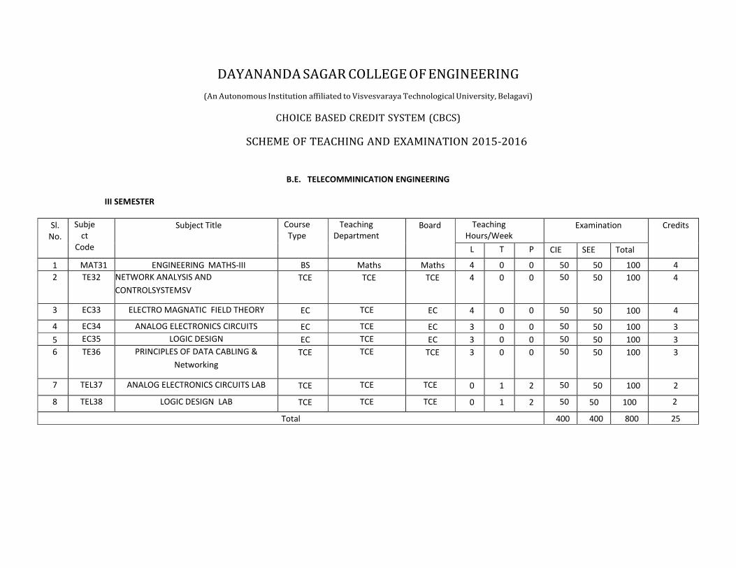
SEE –Semester End Examination Theory (50 Marks)
Bloom’s Category Marks Theory(50)
Remember 10 Understand 20 Apply 5 Analyze 5 Evaluate 10 Create

Network Analysis & Control system
Course code: TE32 Credits: 04 L: P: T: S: 4: 0: 0: 0 CIE Marks: 50 Exam Hours: 03 SEE Marks: 50 Total Hours: 52 Course Objectives:
1. To comprehend basic concepts of electrical networks with various simplification techniques and also to various network theorems.
2. To discuss transient behavior of electrical components and circuits. 3. To describe and analyse control systems using Block diagram representation, Signal flow graph
techniques and to determine their transfer function. 4. To determine the time domain response of first and second order systems to various types of
inputs. 5. To define and describe stability in control systems, analysis of stability using Routh– Hurwitz
criterion and evaluate stability of systems using Root-locus techniques.
Course Outcomes: After completion of the course, the graduates will be able to
CO1 Apply fundamental Knowledge of engineering and network analysis techniques to solve the challenges in the fields of electrical circuits.
CO2 Distinguish and analyze behavior of circuit elements at different scenarios
CO3 Design the electrical circuit with specific needs using the various electrical components and its approaches
CO4 Conduct investigations of complex problems of electrical components and its applications
CO5 Acquire knowledge of Basic Concepts of Control Systems and determine its transfer function.
CO 6 Analyze whether the system is of first order or second order for a given step response for a system and able to debug by focusing on the pattern generated by the different arrays of antennas.
CO PO1 PO2 PO3 PO4 PO5 PO6 PO7 PO8 PO9 PO10 PO11 PO12 PSO1 PSO2 PSO3
CO1 3 2 2 2
CO2 3 3 2 2
CO3 3 3 2 1 2

CO4 3 3 3 2 1
CO5 3 3 3 2 2
CO6 3 3 3 2 2
Cii 3 3 3 2 2
Unit Course Content Hours COs
1
INTRODUCTION
Basic Concepts: Basic definitions. Practical sources, Source transformations, Loop and node analysis with linearly dependent and independent sources for DC and AC networks, Concepts of super node and super mesh.
11 CO1
2
Network Theorems: Superposition theorem, Thevinin’s theorem, Norton’s
theorem and Maximum Power transfer theorem Two port network parameters: Definition of z, y, h and transmission parameters, modeling with these parameters, and relationship between parameters sets.
11 CO1
3
Resonance circuits, Transient behavior and initial conditions: Series and parallel resonance, frequency response of series and Parallel circuits, Q –factor, Bandwidth. Behavior of circuit elements under switching condition and their Representation,
evaluation of initial and final conditions in RL, RC and RLC circuits for AC and
DC excitations
10 CO2
4
Introduction: Introduction to Control Systems, Types of Control Systems, Effect of Feedback Systems. Block diagrams and Signal flow graphs: Introduction to block diagram and Signal Flow Graph, finding Transfer Function for Signal flow graph using Mason’s Gain Formula. Time Response of feedback Control Systems: Standard test signals, Unit step response of First and second order systems, Time response specifications, Time response specifications of second order systems, steady – state errors and error constants.
10 CO3
5
Stability analysis: Concepts of stability, Necessary and Sufficient conditions for Stability, Routh- stability criterion and problems. Root–Locus Techniques: Introduction, Root locus concepts and Rules, Construction of root loci, gain and phase margins, gain and phase cross over frequency with problems.(excluding complex poles and zeroes)
Note:

1. Questions for CIE and SEE not to be set from self-study component.
2. Assignment Questions should be from self-study component only.
SELF STUDY COMPONENT
UNIT 1 Network reduction using Star– Delta transformation
UNIT 2: : Reciprocity theorem and Millman’s theorem
UNIT 4: Block diagram reduction Techniques
UNHIT 5: Frequency domain Analysis:Introduction, Gain Margin, Phase Margin,Bode Plots.
TEXT BOOKS:
1. “Network Analysis”, M. E. Van Valkenburg, PHI / Pearson Education, 3rd Edition. Reprint 2002. 2. “Networks and systems”, Roy Choudhury, 2nd edition, 2006 re-print, New Age International
Publications. 3. J. Nagarath and M. Gopal, “Control Systems Engineering”, New Age International (P) Limited,
Publishers, Fourth edition – 2005. 4. D. Roy Choudhury, “Modern Control Engineering”, PHI, 2015. ISBN: 9788 1203 21960. REFERENCE BOOKS:
1. “Engineering Circuit Analysis”, Hayt, Kemmerly and DurbinTMH 7th Edition, 2010 2. “Basic Engineering Circuit Analysis”, J. David Irwin / R. Mark Nelms, John Wiley, 8th ed, 2006. 3. “Automatic Control Systems” Benjamin C Kuo and FaridGolnaagi, Wiley Student 8th Edition. 4. Modern Control Engineering” K. Ogata Pearson Education Asia / PHI.
Assessment Pattern:
CIE –Continuous Internal Evaluation Theory (50 Marks)
Bloom’s Category Tests Assignments AAT1 AAT2 Marks (Out of 50) 30 10 05 05 Remember -- -- 02 01 Understand 10 -- 01 01 Apply 10 05 -- 01
Analyze 05 05 02 02 Evaluate 05 Create *AAT 1– Alternate Assessment Tool 1: Quiz AAT 2 - Alternate Assessment Tool 2: Surprise Test
SEE –Semester End Examination Theory (50 Marks)
Bloom’s Category
Marks Theory(50)
Remember 10 Understand 10 Apply 10 Analyze 10 Evaluate 10 Create

ELECTRO MAGNETIC FIELD THEORY
Course code: EC33 Credits: 04 L: P: T: S: 4: 0: 0: 0 CIE Marks: 50 Exam Hours: 03 SEE Marks: 50 Total hours-52 COURSE OBJECTIVES:
To study vectors and 3-dimentional systems
To study the concepts of electric and magnetic fields in 3-dimention
To learn theorems and laws related to electric and magnetic field
To derive Maxwell equations both for static and time varying fields
To relate field theory and circuit theory
COURSE OUTCOMES: At the end of the course, student will be able to
Mapping of Course outcomes to Program outcomes:
PO1 PO2 PO3 PO4 PO5 PO6 PO7 PO8 PO9 PO10 PO11 PO12
CO1 3 2 1 1 1 - - - - - - -
CO2 3 2 1 1 1 - - - - - - -
CO3 3 2 1 1 1 - - - - - - -
CO4 3 2 1 1 1 - - - - - - -
CO5 3 2 1 1 1 - - - - - - -
CO6 3 2 1 1 1 - - - - - - -
Module Course Content Hours COs
1
Vector Analysis, Coordinate Systems: Three dimensional Coordinate systems-Cartesian, cylindrical and Spherical coordinate systems, conversion from one coordinate system to other.
05 CO1 CO2
CO1 Understand the fundamental concepts of vectors and 3-dimentional systems-Conversion of points from one system to other
CO2 Study laws related to electric field such as coulomb’s law, Gauss law, Poisson and Laplace equations-Bring out the circuit concepts such as Energy, Voltage, Current and capacitor from field theory concepts
CO3 Learn laws related to magnetic field such as Biot Savart law, Ampere’s circuital law and Stoke’s theorem-Bring out concepts of Force, torque and Inductance
CO4 Apply laws and theorems learnt to solve application problems
CO5 Consolidate Maxwell’s Equations for static field. Analyze the Boundary conditions for different mediums
CO6 Extend the concepts to time varying fields and generate Maxwell’s equations for time varying fields

Coulomb’s Law and Electric field intensity: Coulomb’s law of charges, Electric field intensity, Field due to line, area and volume charge distributions.
05
2
Electric flux density, Gauss’ law and divergence: Electric flux density, Gauss’ law, Application of gauss law to differential element, Divergence, Maxwell’s First equation (Electrostatics), vector operator and divergence theorem.
05
CO2 CO4 Energy and potential : Energy expended in moving a point charge in
an electric field, The line integral, Definition of potential difference and Potential, The potential field of a point charge and system of charges, Potential gradient , Energy density in an electrostatic field.
05
3
Conductors, dielectrics and capacitance: Current and current density, Continuity of current, Nature of dielectric materials, boundary conditions for perfect Dielectrics, capacitance.
05
CO2 CO4 CO5
Poisson’s and Laplace’s equations: Poisson’s and Laplace’s Equations, Uniqueness theorem, Examples of the solutions to Laplace’s and Poisson’s equations (One dimensional only).
05
4
The steady magnetic field: Biot-Savart law, Ampere’s circuital law, Curl, Stokes’ theorem, magnetic flux and flux density, scalar and Vector magnetic potentials.
05
CO3 CO4
Magnetic forces: Force on a moving charge and differential current element, Force between differential current elements, Force and torque on a closed circuit.
05
5
Magnetic materials and inductance: Magnetization and permeability, Magnetic boundary conditions, Magnetic circuit, Potential energy and forces on magnetic materials, Inductance and Mutual Inductance.
05
CO3 CO4 CO5 CO6
Time varying fields and Maxwell’s equations: Faraday’s law, displacement current, Maxwell’s equation in point and Integral form, retarded potentials.
05
SELF STUDY COMPONENTS: UNIT 1: Review of vectors and vector algebra-simple problems, MATLAB simulations UNIT 2: Application of Gauss law-Some symmetrical charge distributions, MATLAB simulation UNIT 3: Metallic conductors, Conductor properties and boundary conditions, Semiconductors UNIT 4: Derivation of steady magnetic field laws UNIT 5: Nature and classification of magnetic materials, MATLAB simulations TEXT BOOKS:
1. “Engineering Electromagnetics”, William H Hayt Jr. and John A Buck,Tata McGraw-Hill, 7th edition, 2006.
2. “Electromagnetics with Applications”, John Krauss and Daniel A Fleisch, McGraw-Hill, 5th

edition, 1999. 3. “Electromagnetics” B. B. Laud, New Age International(p) Ltd N Delhi (1987)
REFERENCE BOOKS:
1. “Elements of Electromagnetic ” Mathew N.O Sadiku, New York – Oxford University Press, Fourth Edition,2007
2. “Field and Wave Electromagnetics”, David K Cheng, Pearson Education Asia, 2nd edition, - 1989, Indian Reprint – 2001.
3. “Fundamentals of Electromagnetics with MATLAB”, Karl Lonngen,Sava .Savov,Randy J.Jost, PHI-second Edition-2012
ASSESSMENT PATTERN: CIE –Continuous Internal Evaluation Theory (50 Marks)
Bloom’s Category Tests Assignments AAT1 AAT2
Marks (Out of 50) 30 10 05 05
Remember 10
Understand 10 05 01 01
Apply 10 05 02 02
Analyze 02
Evaluate 02
Create
*AAT – Alternate Assessment Tool SEE –Semester End Examination Theory (50 Marks)
Bloom’s Category Marks Theory(50)
Remember 10
Understand 10
Apply 10
Analyze 10
Evaluate 10
Create
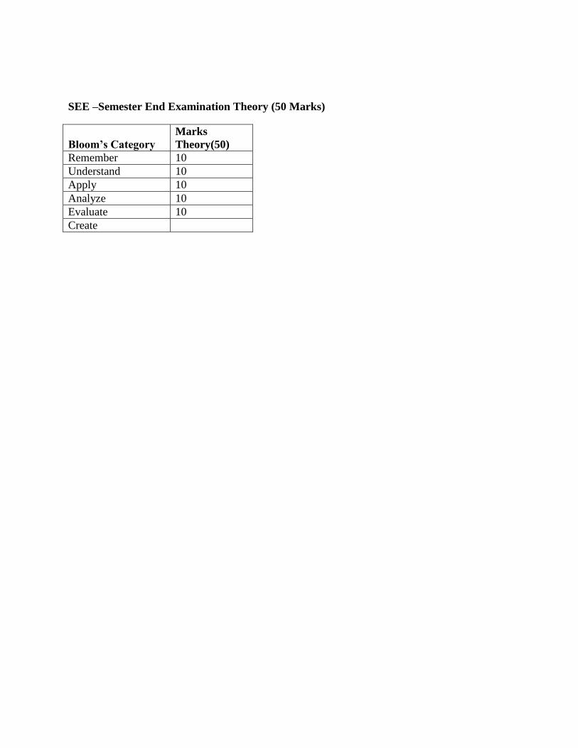
ANALOG ELECTRONIC CIRCUITS Course code: EC34 Credits: 03 L: P: T: S: 3:0:0:0 CIE Marks: 50 Exam Hours: 03 SEE Marks: 50 Total Hours: 40 COURSE OBJECTIVES:
1. Ability to design, conduct and analyze the concepts of Analog Electronic Circuits. 2. Recognize various BJT parameters, connections and configurations. 3. Recall and Recognize construction and characteristics of JFETs and MOSFETs. 4. Demonstrate and generalize Frequency response of BJT at various frequencies. 5. Define, Demonstrate and Analyze Power amplifier circuits in different modes of
operation. 6. Describe, Recognize and Demonstrate Feedback and Oscillator circuits using BJT.
COURSE OUTCOMES: At the end of the course, student will be able to
Mapping of Course outcomes to Program outcomes:
PO1 PO2 PO3 PO4 PO5 PO6 PO7 PO8 PO9 PO10 PO11 PO12
CO1 3 2 1 2 2 1 1
CO2 3 2 1 1 2 1 1
CO3 3 2 2 2 2 1 1
CO4 2 1 1 1 1 1 1
CO5 3 2 1 1 1 1 1
CO6 2 1 1 1 2 1 1
COURSE CONTENT:
Unit Course Content Hours COs
CO1 Design clippers, clampers and voltage multiplier which use diode as one of the circuit element.
CO2 To determine, analyze and design the Q-point of a transistor bias circuit to work as an amplifier.AC Analysis of transistor.
CO3 To Understand the concept of feedback amplifier and oscillator using transistor.
CO4 Interpretation of performance characteristics of power amplifiers and analyze different distortions in amplifiers.
CO5 Ability to understand and study the working principles of MOSFET and Biasing of FETs.
CO6 Apply the knowledge gained in the design of transistorized circuits, amplifiers and Oscillators.
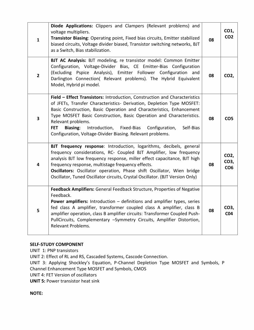
1
Diode Applications: Clippers and Clampers (Relevant problems) and voltage multipliers. Transistor Biasing: Operating point, Fixed bias circuits, Emitter stabilized biased circuits, Voltage divider biased, Transistor switching networks, BJT as a Switch, Bias stabilization.
08
CO1, CO2
2
BJT AC Analysis: BJT modeling, re transistor model: Common Emitter Configuration, Voltage-Divider Bias, CE Emitter-Bias Configuration (Excluding Pspice Analysis), Emitter Follower Configuration and Darlington Connection( Relevant problems). The Hybrid Equivalent Model, Hybrid pi model.
08 CO2,
3
Field – Effect Transistors: Introduction, Construction and Characteristics of JFETs, Transfer Characteristics- Derivation, Depletion Type MOSFET: Basic Construction, Basic Operation and Characteristics, Enhancement Type MOSFET Basic Construction, Basic Operation and Characteristics. Relevant problems. FET Biasing: Introduction, Fixed-Bias Configuration, Self-Bias Configuration, Voltage-Divider Biasing. Relevant problems.
08 CO5
4
BJT frequency response: Introduction, logarithms, decibels, general frequency considerations, RC- Coupled BJT Amplifier, low frequency analysis BJT low frequency response, miller effect capacitance, BJT high frequency response, multistage frequency effects. Oscillators: Oscillator operation, Phase shift Oscillator, Wien bridge Oscillator, Tuned Oscillator circuits, Crystal Oscillator. (BJT Version Only)
08
CO2, CO3, CO6
5
Feedback Amplifiers: General Feedback Structure, Properties of Negative Feedback. Power amplifiers: Introduction – definitions and amplifier types, series fed class A amplifier, transformer coupled class A amplifier, class B amplifier operation, class B amplifier circuits: Transformer Coupled Push-PullCircuits, Complementary –Symmetry Circuits, Amplifier Distortion, Relevant Problems.
08 CO3,C04
SELF-STUDY COMPONENT UNIT 1: PNP transistors UNIT 2: Effect of RL and RS, Cascaded Systems, Cascode Connection. UNIT 3: Applying Shockley’s Equation, P-Channel Depletion Type MOSFET and Symbols, P Channel Enhancement Type MOSFET and Symbols, CMOS UNIT 4: FET Version of oscillators UNIT 5: Power transistor heat sink NOTE:

1. Questions for CIE and SEE not to be set from self-study component. 2. Assignment Questions should be from self-study component only.
TEXT BOOK:
1. Robert L. Boylestad and Louis Nashelsky, “Electronic Devices and Circuit Theory”, PHI/Pearson Education., 10th Edition, ISBN: 9788131727003.
2. U.B. Mahadevaswamy, “Analog Electronics Circuits: A Simplified Approach”, Pearson/Sanguine, 2007.
3. J. Nagrath, “Electronics: Analog and Digital”, PHI.
REFERENCES BOOKS: 1. Jacob Millman & Christos C. Halkias, “Integrated Electronics”, Tata - McGraw Hill, 2nd
Edition, 2010 2. David A. Bell, “Electronic Devices and Circuits”, PHI, 4th Edition, 2004. 3. Adel Sedra and K.C. Smith, “Microelectronic Circuits”, 5th Edition, Oxford University
Press, Interantional Version, 2009. ASSESSMENT PATTERN: CIE –Continuous Internal Evaluation Theory (50 Marks)
Bloom’s Category Tests Assignments AAT1 AAT2
Marks (Out of 50) 30 10 05 05
Remember 10 01
Understand 10 05 02 01
Apply 10 05 02 01
Analyze 01 02
Evaluate
Create
*AAT 1– Alternate Assessment Tool 1: Quiz
AAT 2 - Alternate Assessment Tool 2: Surprise Test SEE –Semester End Examination Theory (50 Marks)
Bloom’s Category Marks Theory(50)
Remember 10
Understand 20
Apply 10
Analyze 10
Evaluate
Create

LOGIC DESIGN
Course code: EC35 Credits: 03 L: P: T: S: 3: 0: 0: 0 CIE Marks: 50 Exam Hours: 03 SEE Marks: 50
Total Hours: 40 COURSE OBJECTIVES:
1. Illustrate, understand and analyze simplification of algebraic equations using K-Maps and variable entered mapping technique.
2. Define and describe operations of Decoders, Encoders, Multiplexers, Carry look ahead adder and Binary comparators.
3. Define and describe Flip-Flops, Counters and Registers. 4. Design and analysis of counters. 5. Design and develop Mealy and Moore models for digital circuits. 6. Design and develop Synchronous Sequential Circuits, State diagrams and Counters
COURSE OUTCOMES: At the end of the course, student will be able to
Mapping of Course outcomes to Program outcomes:
PO1 PO2 PO3 PO4 PO5 PO6 PO7 PO8 PO9 PO10 PO11 PO12
CO1 2 - - - - - - - 2 - - -
CO2 2 1 2 1 1 1 - - 2 - - 2
CO3 2 2 2 - 1 - - - 2 - - 2
CO4 2 2 2 - 1 - - - 2 - - 2
CO5 2 2 2 1 1 - - - 2 - - 2
CO6 2 2 2 1 1 - - - 2 - - 2
CO1 Acquire knowledge of Combinational Logic, Simplification Techniques using Karnaugh Maps and Variable entered mapping technique.
CO2 Acquire knowledge of operation of Decoders, Encoders, Multiplexers, Carry look ahead adders and Comparators.
CO3 Acquire knowledge of operation of Latches, FlipFlops, Counters and Registers.
CO4 Design and analysis of combinational circuits and sequential circuits.
CO5 Design and develop Mealy and Moore Models for digital circuits.
CO6 Apply the knowledge gained in the Synchronous Sequential Circuits, State diagrams and Counters.

Unit Contents of the Unit Hours COs
1
Principles of combinational logic: Definition of combinational logic, Canonical forms, Generation of switching equations from truth tables, Karnaugh maps-3, 4 and 5 variables, Incompletely specified functions (Don’t Care terms), Simplifying Max term equations. Variable Entered Mapping Technique.
08 CO1
2
Analysis and design of combinational logic: General approach, Decoders-BCD decoders, Encoders, Digital multiplexers, using multiplexers as Boolean function generators. Adders and Subtractors, Cascading full adders, Carry Look Ahead Adder, Binary comparators.
08 CO1 CO2 CO4
3
Introduction to Sequential Circuits: Basic Bistable Element, Latches, SR Latch, Application of SR Latch, A Switch Debouncer, The Clocked SR Flip Flop, JK Flip Flop, The Master-Slave JK Flip-flop, Edge Triggered Flip-Flops. Characteristic equation and Timing diagram of Flip-Flop circuits.
08 CO1C
O3
4
Sequential Circuit Design: Registers, Counters - Binary Ripple Counters, Synchronous Binary counters, Counters based on Shift Registers, Design of a Synchronous counters.
08 CO4
5
Sequential design: Introduction, Mealy and Moore Models, State Machine Notation, Synchronous Sequential Circuit Analysis and Design. 08
CO5 CO6
SELF STUDY COMPONENT: UNIT 1: Quine-McCluskey minimization technique.. UNIT 2: Design methods of building blocks of combinational logics. UNIT 3: Conversion of Flip-Flops UNIT 4: Case study of Sequence generator. UNIT 5: Construction of state Diagrams, Counter Design. Note:
1. Questions for CIE and SEE not to be set from self-study component. 2. Assignment Questions should be from self-study component only.
TEXT BOOKS:
1. Donald D Givone, “Digital Principles and Design”, Tata McGraw Hill Edition, 2002. 2. R.P. Jain, “Modern Digital Electronics”, Tata McGraw-Hill Education, 3rd edition. 3. M Morris Mono, “Digital Logic and computer design”, Prentice Hall.
REFERENCE BOOKS:

1. Charles H Roth, Jr., “Fundamentals of logic design”, Thomson Learning, 2004. 2. Mono and Kim, “Logic and computer design Fundamentals”, Pearson, Second Edition,
2001. 3. Ronald J Tocci, Neal S. Wildmer, and Gregory L. Moss, “Digital Systems: Principles and
Applications”, Pearson, 9th Edition. 4. William I. Fletcher, “An Engineering Approach to Digital Design”, Prentice-Hall, 1980
ASSESSMENT PATTERN:
CIE –Continuous Internal Evaluation Theory (50 Marks)
Bloom’s Category Tests Assignments AAT1 AAT2
Marks (Out of 50) 30 10 05 05
Remember 05 01 01
Understand 10 05 02 01
Apply 10 05 01
Analyze 05 02 02
Evaluate
Create
*AAT 1– Alternate Assessment Tool 1: Quiz AAT 2 - Alternate Assessment Tool 2: Surprise Test SEE –Semester End Examination Theory (50 Marks)
Bloom’s Category Marks Theory(50)
Remember 10
Understand 10
Apply 10
Analyze 20
Evaluate
Create

Principles of data cabling and Networking
Course code: TE36 Credits: 03 L: P: T: S: 3: 0: 0: 0 CIE Marks: 50 Exam Hours: 03 SEE Marks: 50 Total Hours: 40 Course Objectives:
1. Understand various cabling specifications and standards from installation and manufacturability perspective.
2. Comprehend various cabling components from domestic and corporate installation perspective.
3. Diagnose faults, defects in cable installation and their rectification through standard testing methodologies.
Course Outcomes: After completion of the course, the graduates will be able to
CO1 Able to comprehend the cabling specifications due to various standards organizations.
CO2 Able to understand technicalities behind various cabling components and procedure behind cabling process.
CO3 Able to understand various installation topologies and testing procedures.
CO4 Able to understand the power levels, data rates in the cable networks with the awareness to adequate security, safety and cross talk.
CO5 Prioritize cabling topologies for successful cabling installation
CO6 Able to test and trouble shoot the Real time problems of cabling system
Mapping of Course outcomes to Program outcomes:
PO1 PO2 PO3 PO4 PO5 PO6 PO7 PO8 PO9 PO10 PO11 PO12
CO1 3 2 1 1 1 - - - 1 1
CO2 3 2 1 1 1 - - - - 1 1 -
CO3 3 2 1 1 1 - - - - 1 1 -

CO4 3 2 1 1 1 - - - - 1 1 -
CO5 3 2 1 1 1 - - - - 1 1 -
CO6 3 2 1 1 1 - - - - 1 1 -
Unit Course Content Hours COs
1
Introduction to data cabling: The importance of Reliable cabling, Cabling and the need for speed, Cable design, Data Communications, Speed Bumps, Types of cross talk, Topologies, Network applications. Cabling Specification and standardization: Structured cabling and standardization, Standards and Specification Organizations.
Cabling system Components: The cable, Wall plates and connectors, Cabling pathways, Telecommunications Rooms, Enclosures, and Equipment Rooms. TIA/EI A Recommendations for Telecommunications Rooms.
08 CO1, CO2
2
Copper Cable Media: Types of copper cabling, Best practices for copper Installation, Coaxial Cable, Hybrid or Composite Cable, Installing Copper Cable, Avoiding Electromagnetic Interference, Copper Cable for Data Applications, Copper Cable for Voice Applications, Testing. Fiber-optic media: Introducing fiber-optic transmission, Advantages of fiber optic cabling, Disadvantages of fiber optic cabling, Types of fiber optic cables, Fiber installation issues, the advantage of optical fiber over copper, basic fiber optic system considerations Link performance analysis.
08 C01, CO2
3
Wall Plates:Wall plate design and installation issues, Fixed-design wall plates, Modular wall plates, Biscuit Jacks. Connectors:Twisted pair cable connectors, coaxial cable connectors, Fiber optic cable connectors. Network Equipment: Network Connectivity Devices, Workstation Ports, Repeaters and Hubs, Bridges, Switches, Servers, and Routers. Wireless networks:Infra transmissions, Advantages of Infrared, RF
systems, Microwave communication
08 CO3
4
Cable system design and installation: Elements of a successful cabling installation, Cabling topologies, cabling plant uses, Choice of Media, Telecommunications rooms, Cabling Management, Data and Cabling Security, Cabling Installation Procedures. Cable Connector Installation: Twisted-pair cable connector installation, Coaxial Cable Connector Installation, Fiber-Optic Cable Connector Installation.
08 CO4,CO5,CO6
5 Cable System testing and troubleshooting: Installation testing, Cable 08 CO5,
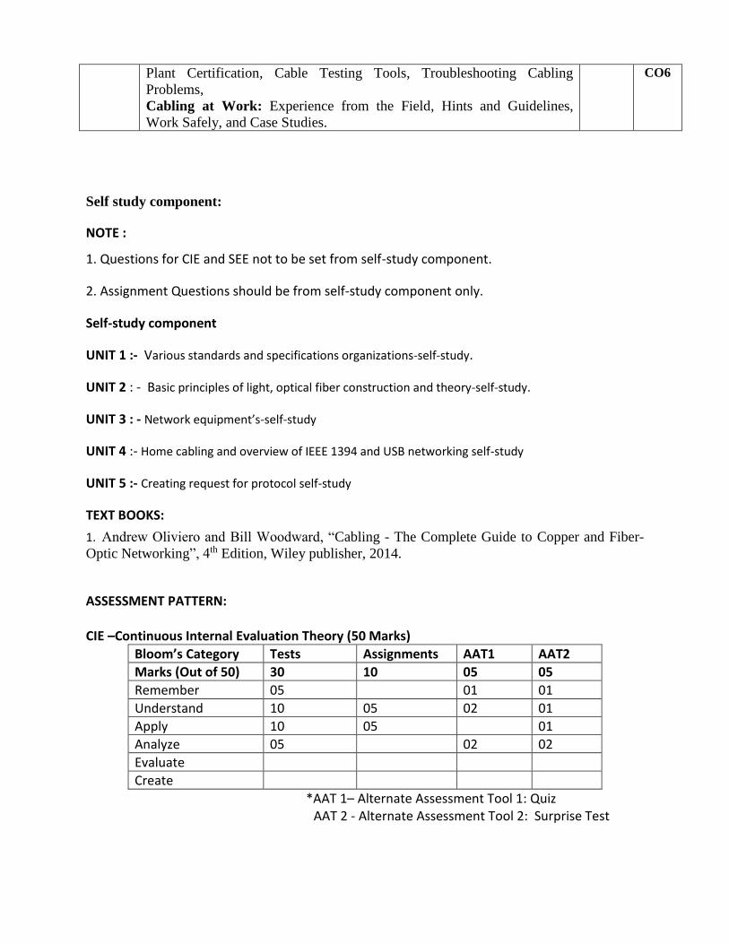
Plant Certification, Cable Testing Tools, Troubleshooting Cabling Problems, Cabling at Work: Experience from the Field, Hints and Guidelines, Work Safely, and Case Studies.
CO6
Self study component:
NOTE :
1. Questions for CIE and SEE not to be set from self-study component.
2. Assignment Questions should be from self-study component only.
Self-study component
UNIT 1 :- Various standards and specifications organizations-self-study.
UNIT 2 : - Basic principles of light, optical fiber construction and theory-self-study.
UNIT 3 : - Network equipment’s-self-study
UNIT 4 :- Home cabling and overview of IEEE 1394 and USB networking self-study
UNIT 5 :- Creating request for protocol self-study
TEXT BOOKS:
1. Andrew Oliviero and Bill Woodward, “Cabling - The Complete Guide to Copper and Fiber- Optic Networking”, 4th Edition, Wiley publisher, 2014.
ASSESSMENT PATTERN:
CIE –Continuous Internal Evaluation Theory (50 Marks)
Bloom’s Category Tests Assignments AAT1 AAT2
Marks (Out of 50) 30 10 05 05
Remember 05 01 01
Understand 10 05 02 01
Apply 10 05 01
Analyze 05 02 02
Evaluate
Create
*AAT 1– Alternate Assessment Tool 1: Quiz AAT 2 - Alternate Assessment Tool 2: Surprise Test

SEE –Semester End Examination Theory (50 Marks)
Bloom’s Category Marks Theory(50)
Remember 10
Understand 10
Apply 10
Analyze 20
Evaluate
Create

ANALOG ELECTRONIC CIRCUITS LAB
Course code: TEL37 Credits: 02 L: P: T: S: 0: 2: 1: 0 CIE Marks: 50 Exam Hours: 03 SEE Marks: 50 Total Hours: 32 Course Objectives:
1. To study the fundamentals of electronic devices like diode and transistor.
2. To study the performance parameters of RLC circuit.
3. To study various efficient techniques involved for circuit analysis.
4. To study the behavior of single stage, multistage response and various feedback concepts.
5. To study the effects of small and large signal analysis pertaining to analog circuits .
Course Outcomes: After completion of the course, the graduates will be able to
CO1 Apply the fundamental knowledge of basic science in order to be well versed with the electronic components and circuits.
CO2 Analyze and test the performance parameters of RLC circuit and learn efficient techniques for circuit analysis.
CO3 Analyze and construct diode circuits and verify the functionality and expected results.
CO4 Design and demonstrate small and large signal effects pertaining to active and passive components.
CO5 Analyze and evaluate the behavior of multistage response and various feedback concepts related to Bipolar devices.
CO6 Understand the capabilities and limitations of analog circuits and make decisions regarding their best utilization in a specific situation.
Mapping of Course outcomes to Program outcomes:
CO PO1 PO2 PO3 PO4 PO5 PO6 PO7 PO8 PO9 PO10 PO11 PO12 PSO1 PSO2 PSO3
1 3 2 2 1
2 3 3 2 1
3 3 3 3 1
4 3 3 3 3
5 3 3 3 2
6 3 3 3 2 2 2 2

List of Experiments
1. Wiring of RC coupled Single stage BJT amplifier and determination of the gain-frequency response, input and output impedances.
2. Wiring of BJT Darlington Emitter follower and determination of the gain, input and output impedances.
3. Wiring of a two stage BJT Voltage series feedback amplifier and determination of the gain, Frequency response, input and output impedances without feedback.
4. Wiring and Testing for the performance of BJT-RC Phase shift Oscillator for f0 ≤ 10 KHz.
5. Testing for the performance of BJT – Hartley & Colpitt’s Oscillators for RF range f0 ≥100KHz.
6. Testing for the performance of BJT -Crystal Oscillator for f0 > 100 KHz.
7. Testing of Diode clipping (Single/Double ended) circuits for peak clipping, peak detection.
8. Testing of Clamping circuits: positive clamping /negative clamping.
9. Testing of a transformer less Class – B push pull power amplifier and determination of its conversion efficiency.
10. Testing of Half wave, Full wave and Bridge Rectifier circuits with and without Capacitor filter. Determination of ripple factor, regulation and efficiency.
11. Verification of Thevinin’s Theorem and Maximum Power Transfer theorem for DC Circuits.
12. Characteristics of Series and Parallel resonant circuits.

LOGIC DESIGN LAB
Course code: TEL38 Credits: 02 L: P: T: S: 4: 0: 0: 0 CIE Marks: 50 Exam Hours: 03 SEE Marks: 50 Total Hours: 32 Course Objectives:
This laboratory course enables students to get practical experience in design, realization and verification of
1. SOP and POS forms. 2. Half/Full adder and Half/Full Subtractors using logic gates 3. Parallel adder and code converters. 4. Multiplexer using logic gate and IC 5. Demultiplexer /Decoder using logic gate and IC 6. Flip Flops, Counters and Shift register.
Course Outcomes: After completion of the course, the graduates will be able to
CO1 Apply the fundamental concepts of binary logic.
CO2 Formulate the techniques to design an optimal logic circuit using basic and universal gates.
CO3 Analyze combinational circuits and their application as logic design components in digital
systems. CO4 Design combinational circuits to perform specific digital functions using integrated circuits.
CO5 Analyze sequential circuits anddesign sequential applications for digital systems using
integrated circuits.
CO6 Design, analyze and demonstrate a micro digital system.
Mapping of Course outcomes to Program outcomes:
PO1 PO2 PO3 PO4 PO5 PO6 PO7 PO8 PO9 PO10 PO11 PO12
CO1 3 3 3 2 - - - - 2 - - -
CO2 3 3 3 1 - - - - 2 - - -
CO3 3 3 3 1 - - - - 2 - - -
CO4 3 3 2 1 - - - - 2 - - -
CO5 3 3 2 1 - - - - 2 - - -
CO6 3 2 1 1 - - - - 2 - - -
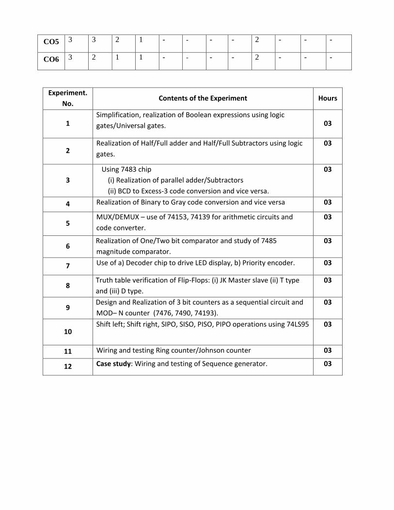
Experiment.
No. Contents of the Experiment Hours
1 Simplification, realization of Boolean expressions using logic
gates/Universal gates. 03
2 Realization of Half/Full adder and Half/Full Subtractors using logic
gates.
03
3
Using 7483 chip
(i) Realization of parallel adder/Subtractors
(ii) BCD to Excess-3 code conversion and vice versa.
03
4 Realization of Binary to Gray code conversion and vice versa 03
5 MUX/DEMUX – use of 74153, 74139 for arithmetic circuits and
code converter.
03
6 Realization of One/Two bit comparator and study of 7485
magnitude comparator.
03
7 Use of a) Decoder chip to drive LED display, b) Priority encoder. 03
8 Truth table verification of Flip-Flops: (i) JK Master slave (ii) T type
and (iii) D type.
03
9 Design and Realization of 3 bit counters as a sequential circuit and
MOD– N counter (7476, 7490, 74193).
03
10 Shift left; Shift right, SIPO, SISO, PISO, PIPO operations using 74LS95 03
11 Wiring and testing Ring counter/Johnson counter 03
12 Case study: Wiring and testing of Sequence generator. 03

DAYANANDA SAGAR COLLEGE OF ENGINEERING
(An Autonomous Institution affiliated to Visvesvaraya Technological University, Belagavi)
CHOICE BASED CREDIT SYSTEM (CBCS) SCHEME OF TEACHING AND EXAMINATION 2015-2016
B.E. TELECOMMINICATION ENGINEERING
IV SEMESTER
Sl. No.
Subject Code
Subject Title Course Type
Teaching Department
Board Teaching Hours/Week
Examination Credits
L T P CIE SEE Total
1 MAT41 ENGINEERING MATHS-IV BS MAT Maths 4 0 0 50 50 100 4
2 EC42 SIGNALS AND SYSTEMS EC TCE EC 4 0 0 50 50 100 4
3 TE43 DIGITAL SYSTEM DESIGN USING VERILOG TCE TCE TCE 4 0 0 50 50 100 4
4 EC 44 LINEAR INTEGRATED CIRCUITS EC TCE EC 3 0 0 50 50 100 3
5 TE 45 Microcontroller and Embedded Processors
(FC)
TCE TCE TCE 3 0 0 50 50 100 3
6 TE46 DIGITAL SWITCHING SYSTEMS TCE TCE TCE 3 0 0 50 50 100 3
7 TEL47 DIGITAL SYSTEM DESIGN LAB TCE TCE TCE 0 1 2 50 50 100 2
8 TEL48 Microcontroller and Embedded Processors LAB
TCE TCE TCE 0 1 2 50 50 100 2
Total 400 400 800 25
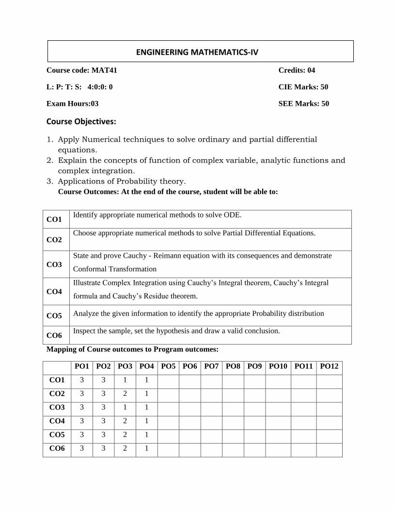
ENGINEERING MATHEMATICS-IV
Course code: MAT41 Credits: 04
L: P: T: S: 4:0:0: 0 CIE Marks: 50
Exam Hours:03 SEE Marks: 50
Course Objectives:
1. Apply Numerical techniques to solve ordinary and partial differential
equations.
2. Explain the concepts of function of complex variable, analytic functions and
complex integration.
3. Applications of Probability theory.
Course Outcomes: At the end of the course, student will be able to:
Mapping of Course outcomes to Program outcomes:
PO1 PO2 PO3 PO4 PO5 PO6 PO7 PO8 PO9 PO10 PO11 PO12
CO1 3 3 1 1
CO2 3 3 2 1
CO3 3 3 1 1
CO4 3 3 2 1
CO5 3 3 2 1
CO6 3 3 2 1
CO1 Identify appropriate numerical methods to solve ODE.
CO2 Choose appropriate numerical methods to solve Partial Differential Equations.
CO3 State and prove Cauchy - Reimann equation with its consequences and demonstrate
Conformal Transformation
CO4 Illustrate Complex Integration using Cauchy’s Integral theorem, Cauchy’s Integral
formula and Cauchy’s Residue theorem.
CO5 Analyze the given information to identify the appropriate Probability distribution
CO6 Inspect the sample, set the hypothesis and draw a valid conclusion.

Module Contents of the Module Hours CO’s
1
NUMERICAL METHODS-1: Numerical solution of Ordinary Differential Equations of first order and first degree: Picard’s method, Taylor’s series method, Modified
Euler’s method, Runge-Kutta method of fourth order, Predictor and Corrector method: Milne’s Method (No derivations of formulae).
12 CO1
2
NUMERICAL METHODS-2: Numerical solution of Partial Differential Equations: Finite difference approximations to derivatives, Numerical solution of one-dimensional heat equation by Schmidt method and by Crank-Nicholson Method, Numerical solution of one-dimensional wave equation.
10 CO2
3
COMPLEX VARIABLES-I: Complex Variables-I: Functions of complex variables, Analytic function, Cauchy-Riemann Equations in cartesian and polar coordinates, Consequences of Cauchy-Riemann Equations, Construction of analytic functions. Transformations: Conformal transformation, Discussion of the
transformations w = z2, w = ez and 𝑤 = 𝑧 +𝑎2
𝑧 (z ≠ 0), Bilinear
transformations
10 CO3
4
COMPLEX VARIABLES-II: Complex integration, Cauchy theorem, Cauchy integral formula. Taylor & Laurent series (statements only). Cauchy residue theorem (statement only).
10 CO4
5
PROBABILITY THEORY: Introduction to probability, Random variables (discrete and continuous), Probability mass function, Probability density function, Cumulative density function, Probability distributions: Geometric and Poisson distributions, Exponential and Normal distributions. Sampling distribution: Samples, Central limit theorem (statement only), Hypothesis testing for means, confidence limits for means, Student’s t-distribution-illustrative examples
10 CO5,CO6
Self-study component: UNIT 1:Adam’s–Bashforth Method (No derivations of formula). UNIT 2:Numerical solution of two-dimensional Laplace’s equation UNIT 3:Transformation 𝑤 = 𝑐𝑜𝑠ℎ𝑧 UNIT 4: Singularities, Poles and Residues.

UNIT 5: Chi-Square distribution as a test of goodness of fit. . Note: NO questions from illustrative examples and from Self Study Component.
Text Books:
1. B.S. Grewal, “Higher Engineering Mathematics” Khanna Publishers, 43rd Edition, 2014 June, ISBN:9788174091956.
2. Erwin Kreyszig; Advanced Engineering Mathematics; John Wiley & Sons, 9th Edition, 2007, ISBN: 9788126531356.
References:
1. B.V.Ramana, “Higher Engineering Mathematics”, Tata Mc Graw-Hill, 2006; ISBN:9780070634190.
2. M. K. Jain, S. R. K. Iyengar and R. K. Jain “Numerical Methods: For Scientific and Engineering Computation”, New Age International Publications, 6th Edition, 2012, ISBN: 9788122433234.
3. Murray Speigel, Schaum's Outline of “Advanced Mathematics for Engineers and Scientists”McGraw-Hill, 1971; ISBN: 9780070602168.
4. Schaum's Outline: Introduction to Probability and Statistics, McGraw Hill
Education (India) Private Limited (1 September 2005); ISBN-13: 978-
0070605015.
Assessment Pattern: CIE –Continuous Internal Evaluation Theory (50 Marks)
Bloom’s Category Tests Assignments AAT1 AAT2 Marks (Out of 50) 30 10 05 05 Remember 10 01 Understand 10 05 01 01 Apply 10 05 02 01 Analyze 02 02 Evaluate Create
*AAT – Alternate Assessment Tool
SEE –Semester End Examination Theory (50 Marks)
Bloom’s Category Marks Theory(50)
Remember 10 Understand 20 Apply 5 Analyze 5 Evaluate 10 Create

SIGNALS & SYSTEMS
Course code: EC 42 Credits: 04 L: P: T: S: 4: 0: 0: 0 CIE Marks: 50 Exam Hours: 03 SEE Marks: 50 Total Hours: 52 COURSE OBJECTIVES: 1. To give the basic introduction to the mathematical analysis of signals and systems. 2. To represent input- output relationships for Linear Time Invariant systems. 3. To understand Fourier and Z-Transforms and their interrelationships. 4. To analyze time-domain and frequency domain approaches for continuous and discrete systems. 5. To apply the Fourier representation on periodic and non periodic signals 6. To examine about the sampling process COURSE OUTCOMES: After completion of the course, the graduates will be able to
CO1 Gain knowledge about signal, system, sampling, time and frequency domain Representation.
CO2 Understand various types of signals, systems, tools used for analysis in frequency domain (ZT, FT & FS) and sampling process.
CO3 Analyze various operations performed on signals, LTI system by different methods, tools used for analysis in frequency domain and sampling process.
CO4 Apply various operations on signals and perform Fourier analysis for different signals.
CO5 Validate properties of LTI systems in time and frequency domain.
CO6 Validate different signals in frequency domain. (Using ZT, FT & FS).
Mapping of Course outcomes to Program outcomes:
PO1 PO2 PO3 PO4 PO5 PO6 PO7 PO8 PO9 PO10 PO11 PO12
CO1 3 3 2 2 - - - - - - - -
CO2 3 3 2 2 - - - - - - - -
CO3 3 3 3 3 - - - - - - - -
CO4 3 3 2 3 - - - - - - - -
CO5 3 3 2 3 - - - - - - - -
CO6 3 3 2 3 - - - - - - - -

Unit Course Content Hours COs
1
Introduction: Definitions of a signal and system, Classification of signals: CT & DT, Even &Odd, Periodic & Non-periodic, Deterministic and Random, Energy & Power, Basic Operations on signals: Operation performed on dependent and independent variable, Impulse Function and its properties.
11
CO1, CO2, CO3
2
System: Properties of systems: Stability, Memory, Causality, Invertibility, Time Invariance and Linearity.Time-domain representations for LTI systems: Introduction, Convolution Sum and Evaluation Procedure, The Convolution Integral, Evaluation Procedure.
10
CO1, CO2, CO3,CO5
3
Time-domain representations for LTI systems: Differential and Difference Equation Representations of LTI Systems, Solving difference equation.Z-Transforms: (*Brief review of Z-Transforms) properties of ROC, properties of Z-transforms, Inversion of the z-Transforms, the Transfer function, Causality and Stability, the unilateral Z - Transforms.
11
CO1, CO2, CO3,CO5,CO6
4
Fourier representation for signals: Introduction, Discrete time and continuous time Fourier series (derivation of series excluded) and their properties (derivation of properties excluded). Discrete and continuous Fourier transforms (derivations of transforms are excluded) and their properties (derivation of properties excluded), Problems.
10
CO1, CO2, CO3,CO4CO6
5
Applications of Fourier representations [Qualitative analysis]: Introduction, Convolution and Multiplication with mixtures of Periodic and Non periodic signals, Sampling: Sampling CT Signals, Sub sampling: Sampling DT Signals, Reconstruction of continuous time signals from samples: Sampling Theorem, Ideal Reconstruction.
10
CO1, CO2, CO3,CO4,CO6
SELF STUDY COMPONENT: UNIT 1: Elementary signals: Exponential, Sinusoidal, Step, Ramp. UNIT 2: Systems viewed as Interconnections of operations. UNIT 3: Relation between LTI system properties and the impulse response, Step Response, Block diagram representations UNIT 5: Fourier transforms representation of periodic signals: Relating the FT to the FS, Relating the DTFT to the DTFS, Fourier transforms representation of discrete time signals: Relating the FT to the DTFT, Relating the FT to the DTFS Note: 1. Questions for CIE and SEE not to be set from self-study component. 2. Assignment Questions should be from self-study component only.

TEXT BOOKS 1. Simon Haykin, “Signals and Systems”, John Wiley India Pvt. Ltd., 2nd
Edn, 2008.
2. H. P Hsu, R. Ranjan, Scham’s outlines of “Signals and Systems, ”TMH, 2006.
REFERENCE BOOKS
1. Michael Roberts, “Fundamentals of Signals & Systems”, 2nd Edition, Tata McGraw Hill, 2010.
2. Alan V Oppenheim, Alan S, Willsky and A Hamid Nawab, “Signals and Systems”, Pearson Education Asia / PHI, 2nd Edition, 1997. Indian Reprint 2002. 3. B. P. Lathi, “Linear Systems and Signals”, Oxford University Press, 2005. 4. Vinay K. Ingle and John G. Proakis, “Digital Signal Processing Using MATLAB”, Cengage Learning, Third Edition 2012. ASSESSMENT PATTERN: CIE –Continuous Internal Evaluation Theory (50 Marks)
Bloom’s Category Tests Assignments AAT1 AAT2
Marks (Out of 50) 30 10 05 05
Remember -- -- 02 01
Understand 10 -- 01 01
Apply 10 05 -- 01
Analyze 05 05 02 02
Evaluate 05
Create
*AAT 1– Alternate Assessment Tool 1: Quiz
AAT 2 - Alternate Assessment Tool 2: Surprise Test SEE –Semester End Examination Theory (50 Marks)
Bloom’s Category
Marks Theory(50)
Remember 10
Understand 10
Apply 10
Analyze 10
Evaluate 10
Create

DIGITAL SYSTEM DESIGN USING VERILOG
Course code: TE43 Credits: 04 L: P: T: S: 4: 0: 0: 0 CIE Marks: 50 Exam Hours: 03 SEE Marks: 50 Total Hours: 52 Course Objectives:
1. Appreciate the importance of Verilog in digital system design.
2. Design combinational and sequential circuits. 3. Discuss different memory types and design synchronous sequential
circuits.
Course Outcomes: After completion of the course, the graduates will be able to
CO1 Apply the fundamentals of digital logic
to design digital system using Verilog. CO2 Formulate the digital system based on models expressed in hardware description language.
CO3 Design combinational circuits that implement arithmetic and logical operations.
CO4 Design sequential systems for storing information and counting events using Verilog.
CO5 Evaluate the functional performance of various memory units and implementation
techniques.
CO6 Successfully synthesize, simulate and implement simple digital systems using modern tools.
Mapping of Course outcomes to Program outcomes:
PO1 PO2 PO3 PO4 PO5 PO6 PO7 PO8 PO9 PO10 PO11 PO12
CO1 3 3 3 2 1 - - - - - - -
CO2 3 3 3 1 1 - - - - - - -
CO3 3 3 2 1 1 - - - - - - -
CO4 3 3 2 1 1 - - - - - - -
CO5 3 3 2 1 1 - - - - - - -
CO6 3 2 1 1 1 - - - - - - -
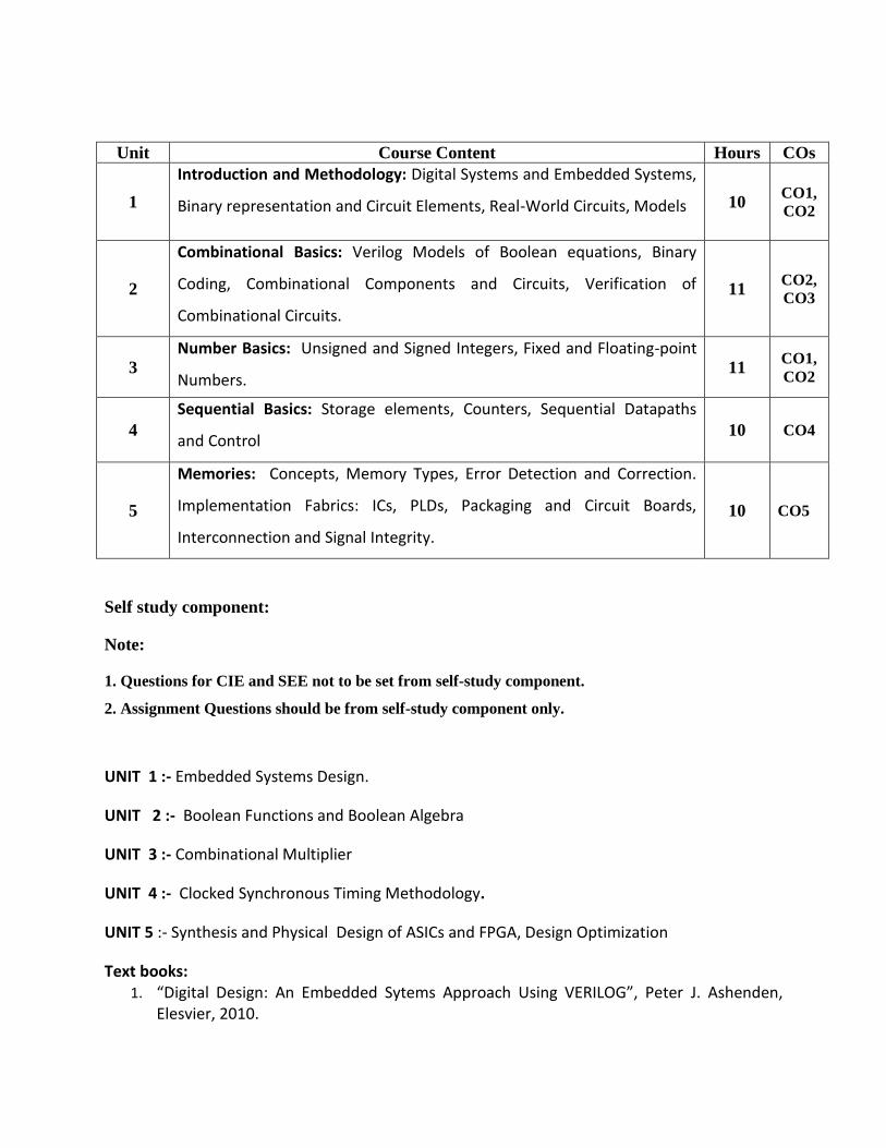
Unit Course Content Hours COs
1
Introduction and Methodology: Digital Systems and Embedded Systems,
Binary representation and Circuit Elements, Real-World Circuits, Models 10 CO1, CO2
2
Combinational Basics: Verilog Models of Boolean equations, Binary
Coding, Combinational Components and Circuits, Verification of
Combinational Circuits.
11 CO2, CO3
3 Number Basics: Unsigned and Signed Integers, Fixed and Floating-point
Numbers. 11 CO1,
CO2
4 Sequential Basics: Storage elements, Counters, Sequential Datapaths
and Control 10 CO4
5
Memories: Concepts, Memory Types, Error Detection and Correction.
Implementation Fabrics: ICs, PLDs, Packaging and Circuit Boards,
Interconnection and Signal Integrity.
10 CO5
Self study component:
Note:
1. Questions for CIE and SEE not to be set from self-study component.
2. Assignment Questions should be from self-study component only.
UNIT 1 :- Embedded Systems Design.
UNIT 2 :- Boolean Functions and Boolean Algebra
UNIT 3 :- Combinational Multiplier
UNIT 4 :- Clocked Synchronous Timing Methodology.
UNIT 5 :- Synthesis and Physical Design of ASICs and FPGA, Design Optimization
Text books: 1. “Digital Design: An Embedded Sytems Approach Using VERILOG”, Peter J. Ashenden,
Elesvier, 2010.

Reference Books:
1. Stephen Brown, ZvonkoVranesic ,Fundamentals of Digital logic with VERILOG design, TMH. 2. Samir Palnitkar, VERILOG HDL-A Guide to digital design and synthesis, 2nd edition,Pearson education.2003.
Assessment Pattern:
CIE –Continuous Internal Evaluation Theory (50 Marks)
Bloom’s Category Tests Assignments AAT1 AAT2 Marks (Out of 50) 30 10 05 05 Remember -- -- 02 01 Understand 10 -- 01 01 Apply 10 05 -- 01 Analyze 05 05 02 02 Evaluate 05 Create *AAT 1– Alternate Assessment Tool 1: Quiz AAT 2 - Alternate Assessment Tool 2: Surprise Test SEE –Semester End Examination Theory (50 Marks)
Bloom’s Category
Marks Theory(50)
Remember 10 Understand 10 Apply 10 Analyze 10 Evaluate 10 Create

LINEAR INTEGRATED CIRCUITS AND ITS APPLICATIONS
Course code: EC44 Credits: 03 L: P: T: S: 3: 0: 0: 0 CIE Marks: 50 Exam Hours: 03 SEE Marks: 50 Total Hours: 40 COURSE OBJECTIVES:
1. Define the basic concepts of Op-amp. 2. Define and describe various parameters of Op-amp, its characteristics and
specifications. 3. Discuss the effects of Input and Output voltage ranges upon Op-amp circuits. 4. Sketch and analyze Op-amp circuits to determine Input Impedence, Output Impedence
and other performance parameters. 5. Describe and Sketch the various switching circuits of Op-amp and analyze its
operations. 6. Differentiate between various types of Timer 555, DACs and ADCs and evaluate the
performance of each with neat circuit diagrams and assuming suitable inputs. COURSE OUTCOMES: At the end of the course, student will be able to
Mapping of Course outcomes to Program outcomes:
PO1 PO2 PO3 PO4 PO5 PO6 PO7 PO8 PO9 PO10 PO11 PO12
CO1 3 2 - - 2 - - - 1 - - 2
CO2 3 2 2 2 2 - - - 2 - - 1
CO3 3 3 3 2 3 1 1 - - - 1 2
CO4 3 3 3 2 1 1 - - 1 - 1 2
CO5 3 3 3 1 2 - - - 2 - - 2
CO6 2 3 1 2 2 1 - - 1 - - 1
CO1 Understands the basic concepts of Op-amp
CO2 Acquire knowledge and solve problems related to Op-amp parameters and Op-amp applications
CO3 Analyze the Linear and Non-Linear op-amp circuit applications and some function specific ICs such as voltage regulators, PLL and its applications
CO4 Apply the knowledge gained in the design of practical circuits for amplifiers, oscillators, multivibrators and voltage regulators
CO5 Design the functional blocks with linear integrated circuit
CO6 Evaluate the performance of various Linear and Non-Linear circuits of Op-amp

Unit Course Content Hours COs
1
Operational Amplifier Fundamentals: Basic Op-Amp circuit, Op-Amp parameters – Input and output voltage, CMRR and PSRR, offset voltages and currents, Slew rate, Input and output impedances ,Op-Amps as DC Amplifiers: Biasing Op-Amps, Direct coupled –Voltage Followers, Non-inverting Amplifiers, Inverting amplifiers
08 CO1 CO2
2
Op-Amps as AC Amplifiers: Capacitor coupled Voltage Follower, High input impedance -Capacitor coupled Voltage Follower, Capacitor coupled Non-Inverting Amplifiers, High input impedance - capacitor coupled Non inverting Amplifiers, Capacitor coupled Inverting amplifiers, Capacitor coupled Difference amplifier, setting the upper cut-off frequency
08 CO1 CO2
3
OP-AMP Applications: Voltage sources, current sources and current sinks, Current amplifiers, instrumentation amplifier, precision rectifiers, limiting circuits, sample and hold circuit, Clamping circuits, Peak detectors, phase shift oscillator, Wein bridge oscillator
08
CO2 CO3 CO4 CO5
4
Non-linear circuit applications: crossing detectors, inverting Schmitt trigger circuits, Monostable & Astable multivibrator, Active Filters –First and second order Low pass & High pass filters, Voltage regulators, Series Op-Amp regulator, IC Voltage regulators, 723 general purpose regulator
08
CO2 CO3 CO4 CO5
5
Other Linear IC applications: Basic 555 timer circuit, 555 timer used as Astable and Monostable Multivibrator, PLL-operating principles, VCO; Basic DAC Techniques- weighted resistor DAC, R-2R ladder DAC, A/D converters- counter type ADC, Servo Tracking ADC, Successive Approximation converter
08
CO3 CO4 CO5 CO6
SELF STUDY COMPONENT: Unit-1: Summing amplifiers, Difference amplifier. Unit -2: Bandwidth, Slew rate effects, Op-Amps frequency response and compensation. Unit-3: V to I and I to V converters, Multiplier and divider. Unit -4: Switching regulators Unit -5: Phase detector / comparator, dual slope ADC Note:
1. Questions for CIE and SEE not to be set from self-study component. 2. Assignment Questions should be from self-study component only.
TEXT BOOKS:
1. “Operational Amplifiers and Linear IC’s”, David A. Bell, 2nd edition,PHI/Pearson, 2004.
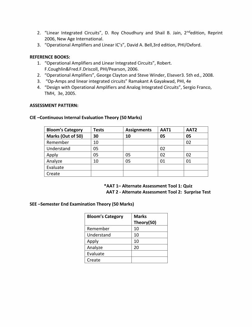
2. “Linear Integrated Circuits”, D. Roy Choudhury and Shail B. Jain, 2ndedition, Reprint 2006, New Age International.
3. “Operational Amplifiers and Linear IC’s”, David A. Bell,3rd edition, PHI/Oxford. REFERENCE BOOKS:
1. “Operational Amplifiers and Linear Integrated Circuits”, Robert. F.Coughlin&Fred.F.Driscoll, PHI/Pearson, 2006.
2. “Operational Amplifiers”, George Clayton and Steve Winder, Elsever3. 5th ed., 2008. 3. “Op-Amps and linear integrated circuits” Ramakant A Gayakwad, PHI, 4e 4. “Design with Operational Amplifiers and Analog Integrated Circuits”, Sergio Franco,
TMH, 3e, 2005. ASSESSMENT PATTERN: CIE –Continuous Internal Evaluation Theory (50 Marks)
Bloom’s Category Tests Assignments AAT1 AAT2
Marks (Out of 50) 30 10 05 05
Remember 10 02
Understand 05 02
Apply 05 05 02 02
Analyze 10 05 01 01
Evaluate
Create
*AAT 1– Alternate Assessment Tool 1: Quiz
AAT 2 - Alternate Assessment Tool 2: Surprise Test SEE –Semester End Examination Theory (50 Marks)
Bloom’s Category Marks Theory(50)
Remember 10
Understand 10
Apply 10
Analyze 20
Evaluate
Create
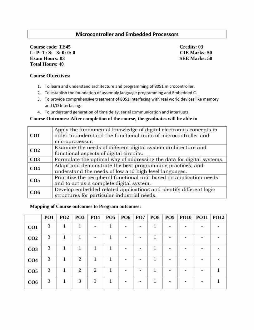
Microcontroller and Embedded Processors
Course code: TE45 Credits: 03 L: P: T: S: 3: 0: 0: 0 CIE Marks: 50 Exam Hours: 03 SEE Marks: 50 Total Hours: 40 Course Objectives:
1. To learn and understand architecture and programming of 8051 microcontroller.
2. To establish the foundation of assembly language programming and Embedded C.
3. To provide comprehensive treatment of 8051 interfacing with real world devices like memory
and I/O Interfacing.
4. To understand generation of time delay, serial communication and interrupts.
Course Outcomes: After completion of the course, the graduates will be able to
CO1 Apply the fundamental knowledge of digital electronics concepts in order to understand the functional units of microcontroller and
microprocessor.
CO2 Examine the needs of different digital system architecture and
functional aspects of digital circuits. CO3 Formulate the optimal way of addressing the data for digital systems.
CO4 Adapt and demonstrate the best programming practices, and understand the needs of low and high level languages.
CO5 Prioritize the peripheral functional unit based on application needs and to act as a complete digital system.
CO6 Develop embedded related applications and identify different logic structures for particular industrial needs.
Mapping of Course outcomes to Program outcomes:
PO1 PO2 PO3 PO4 PO5 PO6 PO7 PO8 PO9 PO10 PO11 PO12
CO1 3 1 1 - 1 - - 1 - - - -
CO2 3 1 1 - 1 - - 1 - - - -
CO3 3 1 1 1 1 - - 1 - - - -
CO4 3 1 2 1 1 - - 1 - - - -
CO5 3 1 2 2 1 - - 1 - - - 1
CO6 3 1 3 3 1 - - 1 - - - 1

Unit Course Content Hours COs
1
MICROPROCESSORS AND MICROCONTROLLER: Introduction, Microprocessors and Microcontrollers, RISC & CISC CPU Architectures, Harvard & Von-Neumann CPU architecture THE 8051 ARCHITECTURE: Introduction, Architecture of 8051, Pin diagram of 8051, Memory organization, External Memory interfacing, stacks. Addressing Modes.
8 CO1
2
INSTRUCTION SET: Instruction timings, 8051 instructions: Data transfer instructions, Arithmetic instructions, Logical instructions, Branch instructions, Subroutine instructions, and Bit manipulation instruction. Assembly language programs and Time delay calculations.
8 CO1
3
8051 TIMERS/COUNTERS: Timers and Counters, 8051 timers/counters, programming 8051 timers in assembly. SERIAL COMMUNICATION: Data communication, Basics of Serial Data Communication, 8051 Serial Communication, connections to RS-232, Serial communication Programming in assembly.
8 CO2
4
INTERRUPTS: Basics of interrupts, 8051 interrupt structure of 8051 Programming timer interrupts, programming external hardware interrupts Programming serial communication interrupts. Interrupt priority in 8051. 8051 INTERFACING AND APPLICATIONS: Basics of I/O concepts, I/O Port Operation, Interfacing 8051 to LCD, Keyboard, Stepper motor interfacing and DC motor interfacing and programming in assembly and C.
8 CO3
5 8085 MICROPROCESSOR: Introduction, features, Architecture, Pin diagram, addressing modes. 8086 MICROPROCESSOR: Features, Architecture, addressing modes.
8 CO4 CO5
Self-study component:
Note:
1. Questions for CIE and SEE not to be set from self-study component.
2. Assignment Questions should be from self-study component only.
UNIT 1: Comparison of different addressing modes.
UNIT 2: Assembler directives.
UNIT 3: Programming timers/counter and serial communication using C.
UNIT 4: Parallel and serial ADC, DAC.
UNIT 5: Instruction Sets of 8085 and 8086 microprocessor.
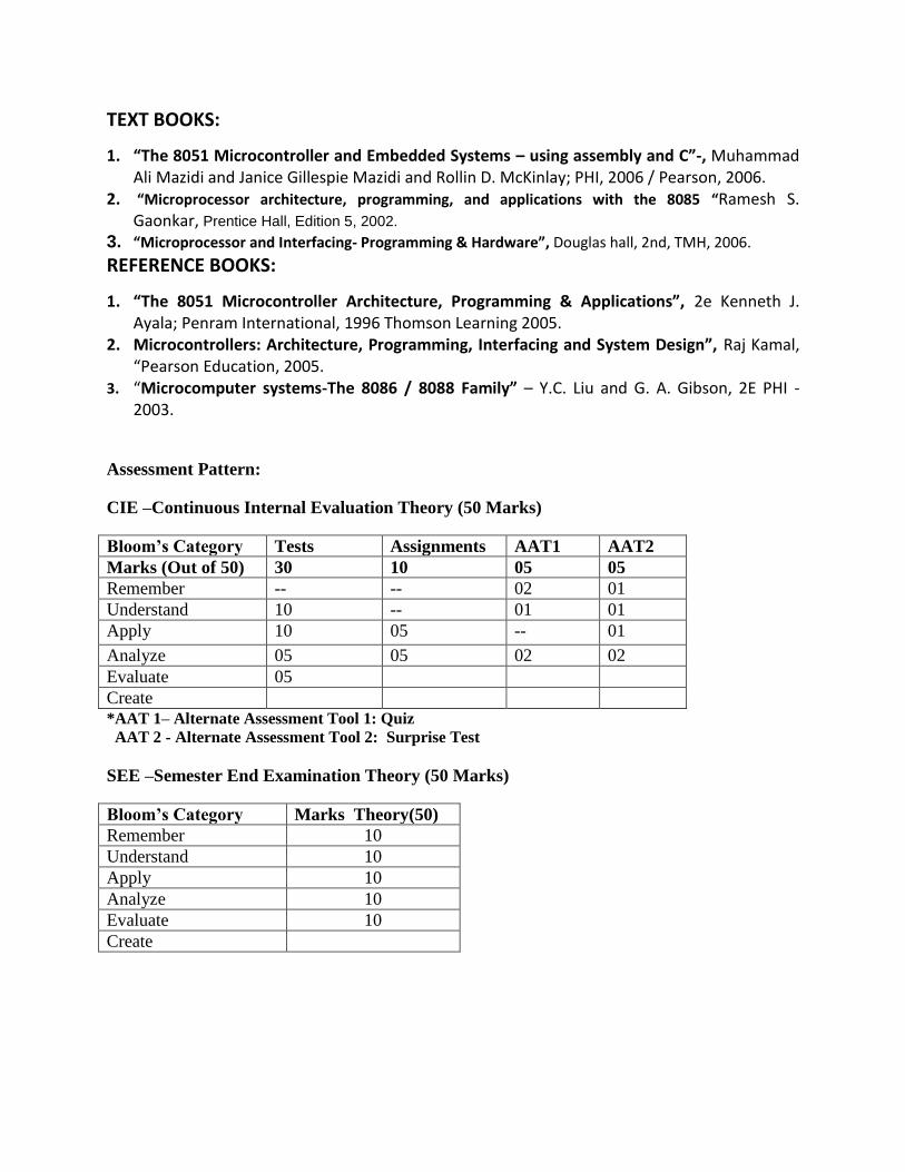
TEXT BOOKS:
1. “The 8051 Microcontroller and Embedded Systems – using assembly and C”-, Muhammad Ali Mazidi and Janice Gillespie Mazidi and Rollin D. McKinlay; PHI, 2006 / Pearson, 2006.
2. “Microprocessor architecture, programming, and applications with the 8085 “Ramesh S. Gaonkar, Prentice Hall, Edition 5, 2002.
3. “Microprocessor and Interfacing- Programming & Hardware”, Douglas hall, 2nd, TMH, 2006.
REFERENCE BOOKS:
1. “The 8051 Microcontroller Architecture, Programming & Applications”, 2e Kenneth J. Ayala; Penram International, 1996 Thomson Learning 2005.
2. Microcontrollers: Architecture, Programming, Interfacing and System Design”, Raj Kamal, “Pearson Education, 2005.
3. “Microcomputer systems-The 8086 / 8088 Family” – Y.C. Liu and G. A. Gibson, 2E PHI -2003.
Assessment Pattern:
CIE –Continuous Internal Evaluation Theory (50 Marks)
Bloom’s Category Tests Assignments AAT1 AAT2 Marks (Out of 50) 30 10 05 05 Remember -- -- 02 01 Understand 10 -- 01 01 Apply 10 05 -- 01 Analyze 05 05 02 02 Evaluate 05 Create *AAT 1– Alternate Assessment Tool 1: Quiz AAT 2 - Alternate Assessment Tool 2: Surprise Test SEE –Semester End Examination Theory (50 Marks)
Bloom’s Category Marks Theory(50) Remember 10 Understand 10 Apply 10 Analyze 10 Evaluate 10 Create
DIGITAL SWITCHING SYSTEMS
Course code: TE46 Credits: 03 L: P: T: S: 4: 0: 0: 0 CIE Marks: 50 Exam Hours: 03 SEE Marks: 50 Total Hours: 40 Course Objectives:
4. To provide fundamentals of digital Switching System and its development
5. Evolution of Digital Switching System from manual to Digital
6. Software – hardware architecture and its maintenance
7. analytical solutions essential for the study of switching system
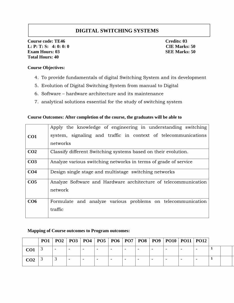
Course Outcomes: After completion of the course, the graduates will be able to
CO1
Apply the knowledge of engineering in understanding switching
system, signaling and traffic in context of telecommunications
networks
CO2 Classify different Switching systems based on their evolution.
CO3 Analyze various switching networks in terms of grade of service
CO4 Design single stage and multistage switching networks
CO5 Analyze Software and Hardware architecture of telecommunication
network
CO6 Formulate and analyze various problems on telecommunication
traffic
Mapping of Course outcomes to Program outcomes:
PO1 PO2 PO3 PO4 PO5 PO6 PO7 PO8 PO9 PO10 PO11 PO12
CO1 3 - - - - - - - - - - - 1 2
CO2 3 3 - - - - - - - - - - 1 2

CO3 3 3 - - - - - - - - - - 1 2
CO4 3 3 - - - - - - - - - - 1 2
CO5 3 3 3 - - - - - - - - - 1 2
CO6 3 3 3 - - - - - - - - - 1 2
Unit Course Content Hours COs
1
FUNDAMENTALS OF SWITCHING SYSTEMS: Developments of
telecommunications, Telecommunications transmission, Power levels,
Four wire circuits, Frequency-Division Multiplexing, Time- Division
Multiplexing, Plesiochronous Digital Hierarchy and Synchronous Digital
Hierarchy.
08 CO1
2
EVOLUTION OF DIGITAL SWITCHING SYSTEMS: Classification of
Switching Systems, Manual System, Strowger Step- by- Step System,
Distribution frames, Crossbar systems, Electronic switching, Digital
switching system, Switching system hierarchy, Evolution of digital
switching systems, Building blocks of a digital switching system, Basic
call processing
08 CO2
3
TELECOMMUNICATIONS TRAFFIC and SWITCHING NETWORKS:
Introduction, Unit of traffic, Congestion, Traffic measurement,
Introduction to switching networks, Different stages of networks,
Gradings,
08 CO3,CO4 CO6
4
SWITCHING SYSTEM SOFTWARE: Basic software architecture, Call
models, Software linkages during a call, Call features, Feature flow
diagram, 08 CO5
5
MAINTENANCE OF DIGITAL SWITCHING SYSTEM AND A GENERIC
MODEL: Software maintenance, Interfaces of a typical Digital Switching
System central office, System Outages and its Impact on Digital Switching
System Reliability, A methodology for reporting and correction of Field
08 CO5
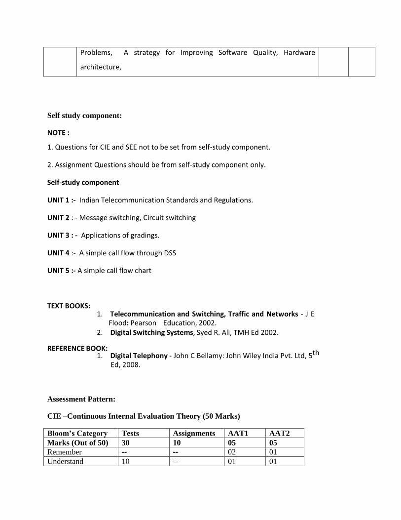
Problems, A strategy for Improving Software Quality, Hardware
architecture,
Self study component:
NOTE :
1. Questions for CIE and SEE not to be set from self-study component.
2. Assignment Questions should be from self-study component only.
Self-study component
UNIT 1 :- Indian Telecommunication Standards and Regulations.
UNIT 2 : - Message switching, Circuit switching
UNIT 3 : - Applications of gradings.
UNIT 4 :- A simple call flow through DSS
UNIT 5 :- A simple call flow chart
TEXT BOOKS: 1. Telecommunication and Switching, Traffic and Networks - J E
Flood: Pearson Education, 2002. 2. Digital Switching Systems, Syed R. Ali, TMH Ed 2002.
REFERENCE BOOK:
1. Digital Telephony - John C Bellamy: John Wiley India Pvt. Ltd, 5th Ed, 2008.
Assessment Pattern:
CIE –Continuous Internal Evaluation Theory (50 Marks)
Bloom’s Category Tests Assignments AAT1 AAT2 Marks (Out of 50) 30 10 05 05 Remember -- -- 02 01 Understand 10 -- 01 01

Apply 10 05 -- 01
Analyze 05 05 02 02 Evaluate 05 Create *AAT 1– Alternate Assessment Tool 1: Quiz AAT 2 - Alternate Assessment Tool 2: Surprise Test SEE –Semester End Examination Theory (50 Marks)
Bloom’s Category
Marks Theory(50)
Remember 10 Understand 10 Apply 10 Analyze 10 Evaluate 10 Create

DIGITAL SYSTEM DESIGN USING VERILOG LAB
Course code: TEL47 Credits: 02 L: P: T: S: 0: 2: 1: 0 CIE Marks: 50 Exam Hours: 03 SEE Marks: 50 Total Hours: 32 Course Objectives:
1. To design combinational and sequential digital circuits. 2. Model combinational and sequential digital circuits by Verilog HDL 3. Design and model digital circuits with Verilog HDL at different levels of abstraction. 4. Synthesize simple digital systems using FPGA.
Course Outcomes: After completion of the course, the graduates will be able to
CO1 Apply the fundamentals of digital logic to simulate digital system using Verilog.
CO2 Design digital system using different description styles.
CO3 Design combinational circuits according to functional behavior using Verilog.
CO4 Design sequential systems using RTL description.
CO5 Successfully synthesize, simulate and implement simple digital systems using modern tools.
CO6 Plan and carry out the simulation of a micro digital system
Mapping of Course outcomes to Program outcomes:
PO1 PO2 PO3 PO4 PO5 PO6 PO7 PO8 PO9 PO10 PO11 PO12
CO1 3 3 3 2 2 - - - 1 1 - -
CO2 3 3 3 1 2 - - - 1 1 - -
CO3 3 3 2 1 2 - - - 1 1 - -
CO4 3 3 2 1 2 - - - 1 1 - -
CO5 3 3 2 1 2 - - - 1 1 - -
CO6 3 2 1 1 2 - - - 1 1 - -
LIST OF EXPERIMENTS:
1. Introduction to CAD tool: Xilinx ISE 10.1i, Simulation using Modelsim: Verilog code for all logic
gates.
2. Data flow modeling: Half Adder, Half Subtractor, Full Adder, Full Subtractor, Multiplexer,
Decoder,2 Bit Comparator.
3. Behavioral modeling for combinational circuits: Full adder, Multiplexer, De-multiplexer,
Binary to gray code converter, 4 Bit Comparator, Encoder(with and without priority).
4. Structural modeling: Full adder.
5. Introduction to logic synthesis onto FPGA kit: Logic synthesis of combinational circuits: Half
Adder, Half Subtractor, Full Adder, Full Subtractor, Multiplexer, Decoder,2 Bit Comparator, Full
adder, Multiplexer, Demultiplexer, Binary to gray code converter, 4 Bit
Comparator,Encoder(with and without priority).
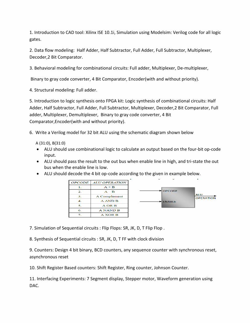
6. Write a Verilog model for 32 bit ALU using the schematic diagram shown below
A (31:0), B(31:0)
ALU should use combinational logic to calculate an output based on the four-bit op-code input.
ALU should pass the result to the out bus when enable line in high, and tri-state the out bus when the enable line is low.
ALU should decode the 4 bit op-code according to the given in example below.
7. Simulation of Sequential circuits : Flip Flops: SR, JK, D, T Flip Flop .
8. Synthesis of Sequential circuits : SR, JK, D, T FF with clock division
9. Counters: Design 4 bit binary, BCD counters, any sequence counter with synchronous reset,
asynchronous reset
10. Shift Register Based counters: Shift Register, Ring counter, Johnson Counter.
11. Interfacing Experiments: 7 Segment display, Stepper motor, Waveform generation using
DAC.

Case Study: Mod-N counter
TEXT BOOKS:
1. Samir Palnitkar, VERILOG HDL-A Guide todigital design and synthesis, 2nd edition,Pearson education.2003.
REFERENCE BOOKS:
1. Wayne Wolf, FPGA based System Design , Pearson Education, 2005
2. Stephen Brown, Zvonko Vranesic, Fundamentals of Digital Logic with Verilog Design, Tata Mc GrawHill,2010.
Microcontrollers and Embedded Processor Lab
Course code: TEL48 Credits: 02 L: P: T: S: 0: 2: 1: 0 CIE Marks: 50 Exam Hours: 03 SEE Marks: 50 Total Hours: 32 Course Objectives:
1. The course syllabus is designed to provide understanding of assembly language programming concepts and improve the programming skill.
2. To provide wide variety of examples with reasonable depth. 3. To familiarize students with different sets if instructions available for programming. 4. To give exposure on interfacing concepts using C and ALP language with different
peripherals. 5. To provide foundation for building innovative projects.
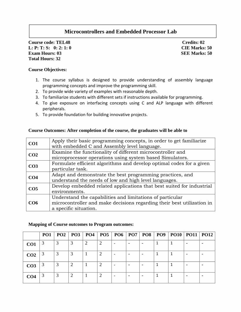
Course Outcomes: After completion of the course, the graduates will be able to
CO1 Apply their basic programming concepts, in order to get familiarize with embedded C and Assembly level language.
CO2 Examine the functionality of different microcontroller and microprocessor operations using system based Simulators.
CO3 Formulate efficient algorithms and develop optimal codes for a given particular task.
CO4 Adapt and demonstrate the best programming practices, and understand the needs of low and high level languages.
CO5 Develop embedded related applications that best suited for industrial environments.
CO6 Understand the capabilities and limitations of particular microcontroller and make decisions regarding their best utilization in a specific situation.
Mapping of Course outcomes to Program outcomes:
PO1 PO2 PO3 PO4 PO5 PO6 PO7 PO8 PO9 PO10 PO11 PO12
CO1 3 3 3 2 2 - - - 1 1 - -
CO2 3 3 3 1 2 - - - 1 1 - -
CO3 3 3 2 1 2 - - - 1 1 - -
CO4 3 3 2 1 2 - - - 1 1 - -

CO5 3 3 2 1 2 - - - 1 1 - -
CO6 3 2 1 1 2 - - - 1 1 - -
LIST OF EXPERIMENTS:
I. Assembly Language Programming
1. Data Transfer – Block move, Exchange, Sorting, Finding largest element in an array. 2. Arithmetic operation: Addition, subtraction, multiplication and division, square, Cube–
bit addressable. 3. Boolean & Logical Instructions: Conditional execution of logical operations. 4. Bit manipulation : Bit addressable memory access 5. Counters : BCD counter using software delay 6. Code conversion: BCD – ASCII; ASCII – Decimal; Decimal – ASCII; HEX – Decimal and
Decimal – HEX. 7. Implementation of Mod counters with 1 sec delay using Timer - 8051 8. Serial data transmission with variable baud rate – 8051
Note: Programming exercise is to be done on both 8051 & 8086.
II. Interfacing Programming in C
1. Generate different waveforms Sine, Square, Triangular, Ramp etc. using DAC interface to 8051; change the frequency and amplitude.
2. Stepper motor interface to 8051. a. Clock wise rotation b. Counter clockwise rotation
3. DC motor interface to 8051 4. Alphanumeric LCD panel interface to 8051 5. Elevator interface to 8051. 6. External ADC and Temperature control interface to 8051.
TEXT BOOKS:
4. “The 8051 Microcontroller and Embedded Systems – using assembly and C”-, Muhammad Ali Mazidi and Janice Gillespie Mazidi and Rollin D. McKinlay; PHI, 2006 / Pearson, 2006.
5. “Microcomputer systems-The 8086 / 8088 Family” – Y.C. Liu and G. A. Gibson, 2E PHI -2003.