Embed Size (px)
Citation preview
David Romo Paterson & Cooke, Chile
Ray Marti nson Paterson & Cooke, Chile
New Projects: Conventional or High Density Tailings?
2
Every new mining project has to define the most important aspects for the business:
• Mineral resources model
• Mine explotation design
• Methallurgicall process
The challenges of new mining projects
After that, the main consumptions of the process have to be evaluated:
• Water consumption
• Energy consumption
At the end, the projects have to define what to do with the waste of the process:
• Sterile material
• Tailings
3
In this case Paterson & Cooke office in Santiago was in charge of the definition of tailings management system of the project.
Aim of the study
The aim of this presentation is to show the issues we had to face and what we did to deal with them, in order to support the definitions of the Client.
“What we have to do is to look at the whole picture of the problem”
4
1. Project overview
2. Tailings deposit location
3. Bench scale tests
4. Conceptual trade off: conventional or thickened tailings?
5. Semi pilot test work
6. Reviewing the solution
7. Conclusion
Content
5
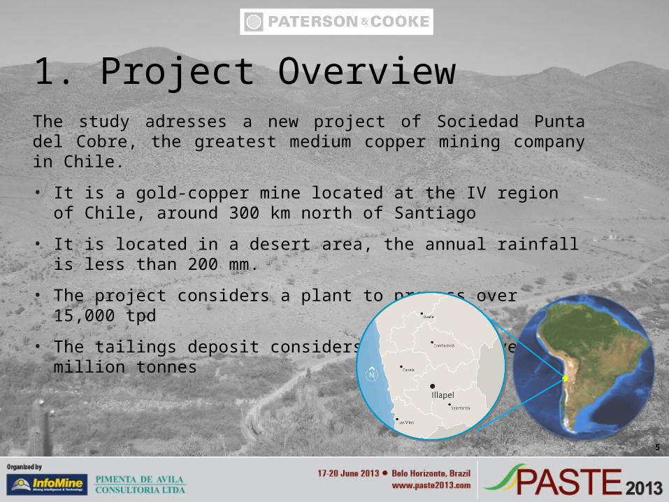
The study adresses a new project of Sociedad Punta del Cobre, the greatest medium copper mining company in Chile.
• It is a gold-copper mine located at the IV region of Chile, around 300 km north of Santiago
• It is located in a desert area, the annual rainfall is less than 200 mm.
• The project considers a plant to process over 15,000 tpd
• The tailings deposit considers a capacity over 100 million tonnes
1. Project Overview
6
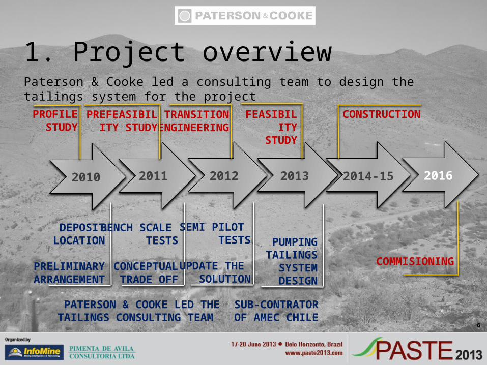
Paterson & Cooke led a consulting team to design the tailings system for the project
1. Project overview
2010 2011 2012 2013 2014-15 2016
TRANSITIONENGINEERING
PREFEASIBILITY STUDY
CONSTRUCTIONFEASIBILITYSTUDY
PROFILESTUDY
COMMISIONING
DEPOSIT LOCATION
PRELIMINARY ARRANGEMENT
BENCH SCALE TESTS
CONCEPTUAL TRADE OFF
SEMI PILOT TESTS
UPDATE THE SOLUTION
PATERSON & COOKE LED THE TAILINGS CONSULTING TEAM
PUMPINGTAILINGS
SYSTEMDESIGN
SUB-CONTRATOROF AMEC CHILE
7
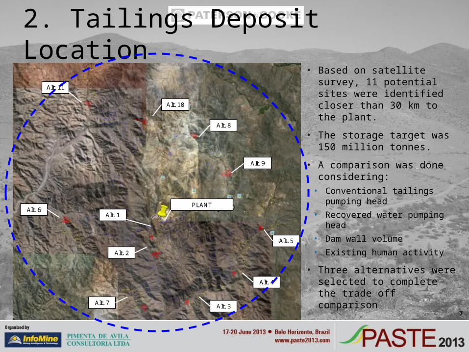
• Based on satellite survey, 11 potential sites were identified closer than 30 km to the plant.
• The storage target was 150 million tonnes.
• A comparison was done considering:
• Conventional tailings pumping head
• Recovered water pumping head• Dam wall volume• Existing human activity
• Three alternatives were selected to complete the trade off comparison
2. Tailings Deposit Location
Alt. 1
Alt. 2
Alt. 3
Alt. 4
Alt. 5
Alt. 9
Alt. 8
Alt. 10
Alt. 11
Alt. 6
Alt. 7
PLANT
8
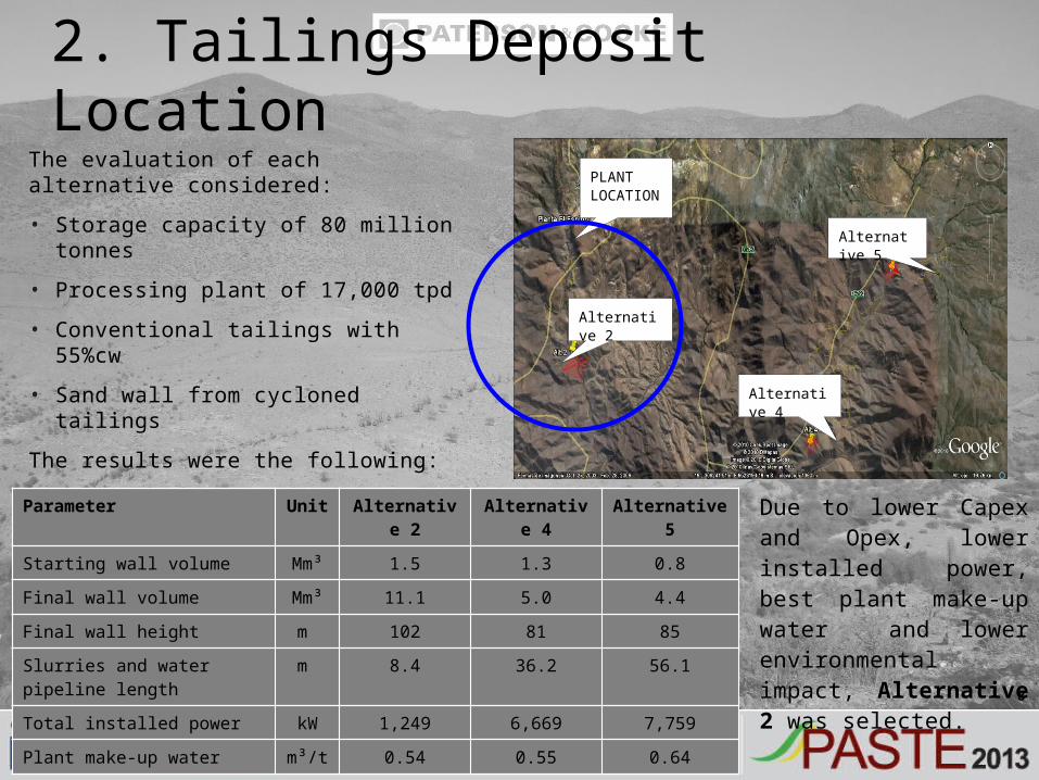
The evaluation of each alternative considered:
• Storage capacity of 80 million tonnes
• Processing plant of 17,000 tpd
• Conventional tailings with 55%cw
• Sand wall from cycloned tailings
The results were the following:
2. Tailings Deposit Location
Alternative 2
Alternative 4
Alternative 5
PLANTLOCATION
Parameter Unit Alternative 2 Alternative 4 Alternative 5
Starting wall volume Mm³ 1.5 1.3 0.8
Final wall volume Mm³ 11.1 5.0 4.4
Final wall height m 102 81 85
Slurries and water pipeline length m 8.4 36.2 56.1
Total installed power kW 1,249 6,669 7,759
Plant make-up water m³/t 0.54 0.55 0.64
Due to lower Capex and Opex, lower installed power, best plant make-up water and lower environmental impact, Alternative 2 was selected.
9
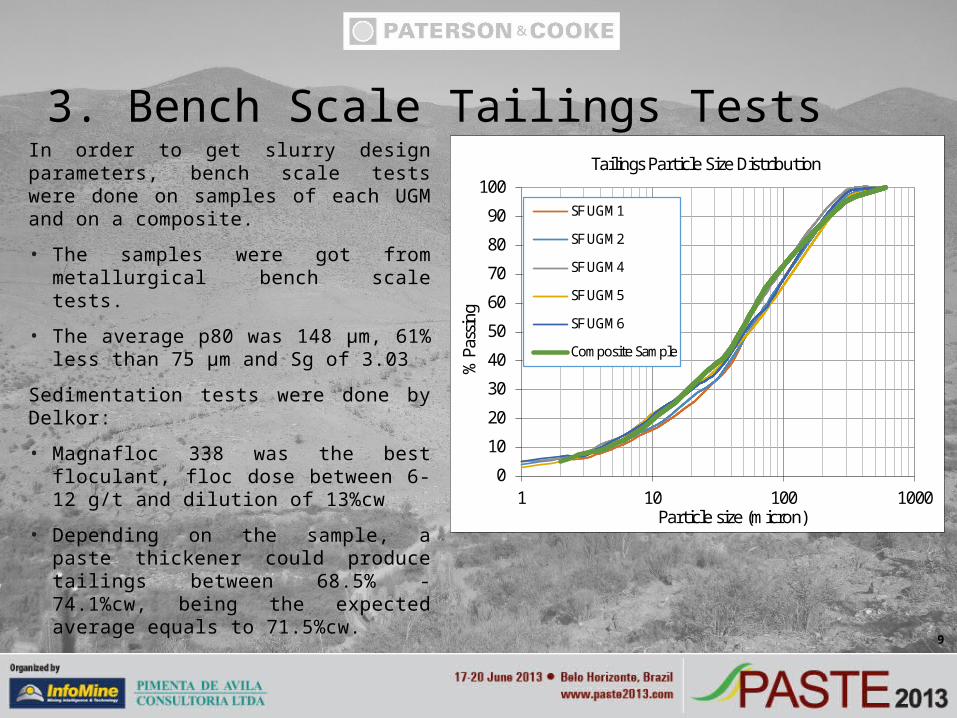
In order to get slurry design parameters, bench scale tests were done on samples of each UGM and on a composite.
• The samples were got from metallurgical bench scale tests.
• The average p80 was 148 μm, 61% less than 75 μm and Sg of 3.03
Sedimentation tests were done by Delkor:
• Magnafloc 338 was the best floculant, floc dose between 6-12 g/t and dilution of 13%cw
• Depending on the sample, a paste thickener could produce tailings between 68.5% - 74.1%cw, being the expected average equals to 71.5%cw.
3. Bench Scale Tailings Tests
0
10
20
30
40
50
60
70
80
90
100
1 10 100 1000
% P
assi
ng
Particle size (micron)
Tailings Particle Size Distribution
SF UGM1
SF UGM2
SF UGM4
SF UGM5
SF UGM6
Composite Sample
10
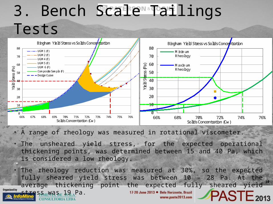
• A range of rheology was measured in rotational viscometer.
• The unsheared yield stress, for the expected operational thickening points, was determined between 15 and 40 Pa, which is considered a low rheology.
• The rheology reduction was measured at 30%, so the expected fully sheared yield stress was between 10 – 28 Pa. At the average thickening point the expected fully sheared yield stress was 19 Pa.
3. Bench Scale Tailings Tests
0
10
20
30
40
50
60
70
80
66% 67% 68% 69% 70% 71% 72% 73% 74% 75% 76%
Yiel
d St
ress
(Pa)
Solids Concentration (Cw)
Bingham Yield Stress vs Solids Concentration
UGM1 (F)UGM2 (F)UGM4 (F)UGM5 (F)UGM 6 (F)Composite Sample (F)Design Curve
0
10
20
30
40
50
60
70
80
66% 68% 70% 72% 74% 76%
Yiel
d St
ress
(Pa)
Solids Concentration (Cw)
Bingham Yield Stress vs Solids Concentration
MinimumRheology
MaximumRheology
11
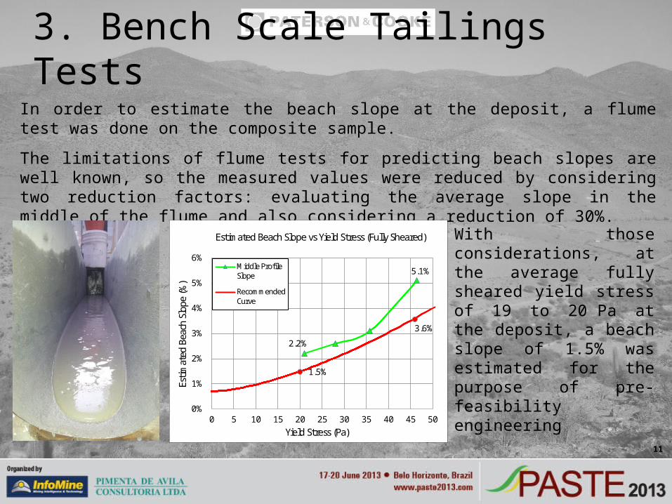
In order to estimate the beach slope at the deposit, a flume test was done on the composite sample.
The limitations of flume tests for predicting beach slopes are well known, so the measured values were reduced by considering two reduction factors: evaluating the average slope in the middle of the flume and also considering a reduction of 30%.
3. Bench Scale Tailings Tests
5.1%
2.2%
1.5%
3.6%
0%
1%
2%
3%
4%
5%
6%
0 5 10 15 20 25 30 35 40 45 50
Estim
ated
Bea
ch S
lope
(%)
Yield Stress (Pa)
Estimated Beach Slope vs Yield Stress (Fully Sheared)
Middle ProfileSlope
RecommendedCurve
With those considerations, at the average fully sheared yield stress of 19 to 20 Pa at the deposit, a beach slope of 1.5% was estimated for the purpose of pre-feasibility engineering
12
The main aspects to figure out in the project in terms of the prefeasibility study were as follows:
• Deposit location
• Tailings management system
• Dam wall and storm water system design
The dam wall and storm water system design were undertaken by Knight Piesold Chile.
Two different options for tailings management system were evaluated:
• Conventional tailings option: low density tailings, cyclons operation, slimes transport, tailings sand wall and tailings discharge at the deposit from the wall.
• Thickened tailings option: high density tailings, wall constructed with borrowed material and tailings discharge at the end of the deposit.
4. Conceptual Trade off: Conventional or Thickened Tailings?
13
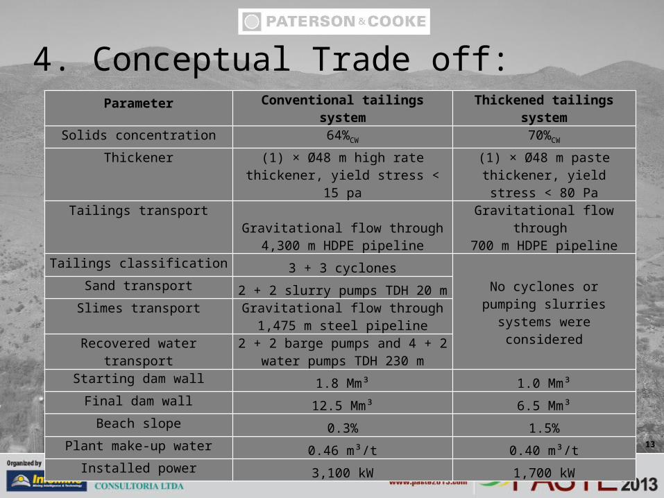
4. Conceptual Trade off:Parameter Conventional tailings system Thickened tailings system
Solids concentration 64%CW 70%CW
Thickener (1) × Ø48 m high rate thickener, yield stress < 15 pa
(1) × Ø48 m paste thickener, yield stress < 80 Pa
Tailings transport Gravitational flow through 4,300 m HDPE pipeline
Gravitational flow through 700 m HDPE pipeline
Tailings classification3 + 3 cyclones
No cyclones or pumping slurries systems were considered
Sand transport2 + 2 slurry pumps TDH 20 m
Slimes transport Gravitational flow through 1,475 m steel pipeline
Recovered water transport 2 + 2 barge pumps and 4 + 2 water pumps TDH 230 m
Starting dam wall1.8 Mm³ 1.0 Mm³
Final dam wall12.5 Mm³ 6.5 Mm³
Beach slope0.3% 1.5%
Plant make-up water0.46 m³/t 0.40 m³/t
Installed power3,100 kW 1,700 kW
14
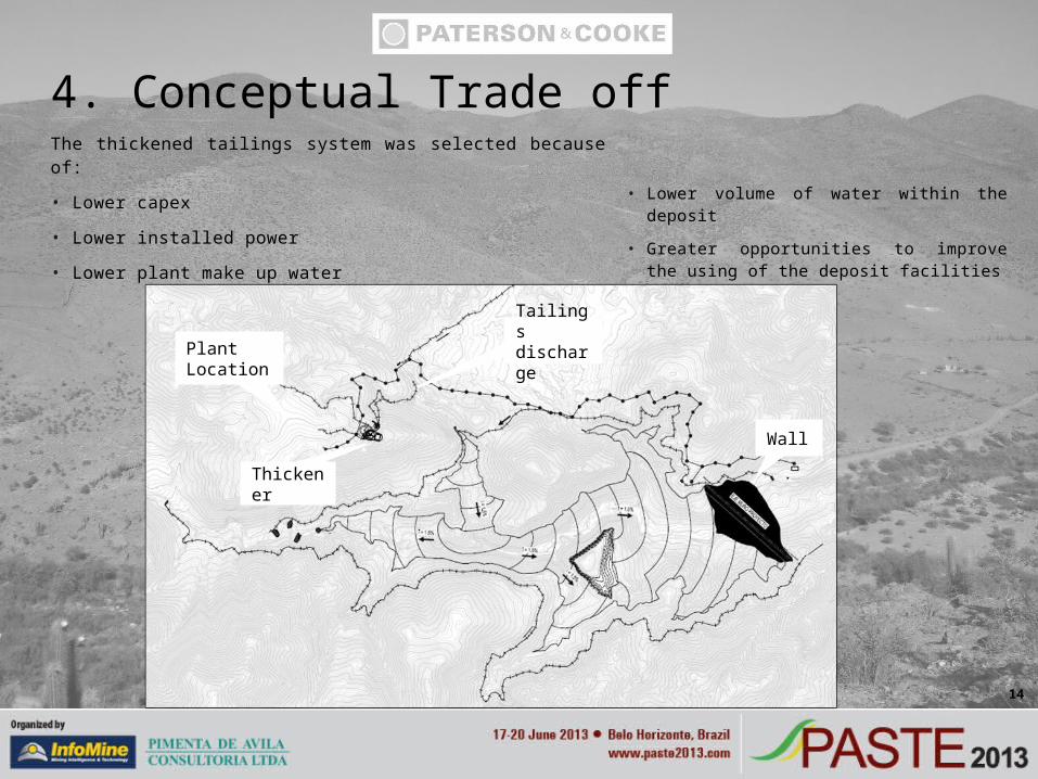
4. Conceptual Trade offThe thickened tailings system was selected because of:
• Lower capex
• Lower installed power
• Lower plant make up water
• Lower volume of water within the deposit
• Greater opportunities to improve the using of the deposit facilities
Wall
Thickener
Plant Location
Tailings discharge
15
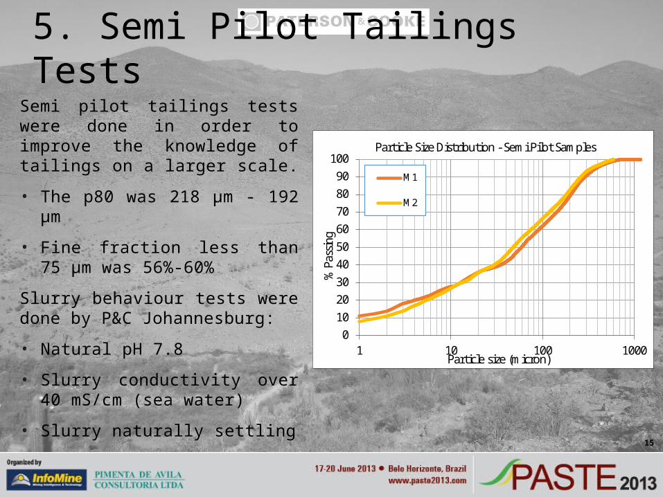
Semi pilot tailings tests were done in order to improve the knowledge of tailings on a larger scale.
• The p80 was 218 μm - 192 μm
• Fine fraction less than 75 μm was 56%-60%
Slurry behaviour tests were done by P&C Johannesburg:
• Natural pH 7.8
• Slurry conductivity over 40 mS/cm (sea water)
• Slurry naturally settling
5. Semi Pilot Tailings Tests
0102030405060708090
100
1 10 100 1000
% P
assi
ng
Particle size (micron)
Particle Size Distribution - Semi Pilot Samples
M1
M2
16
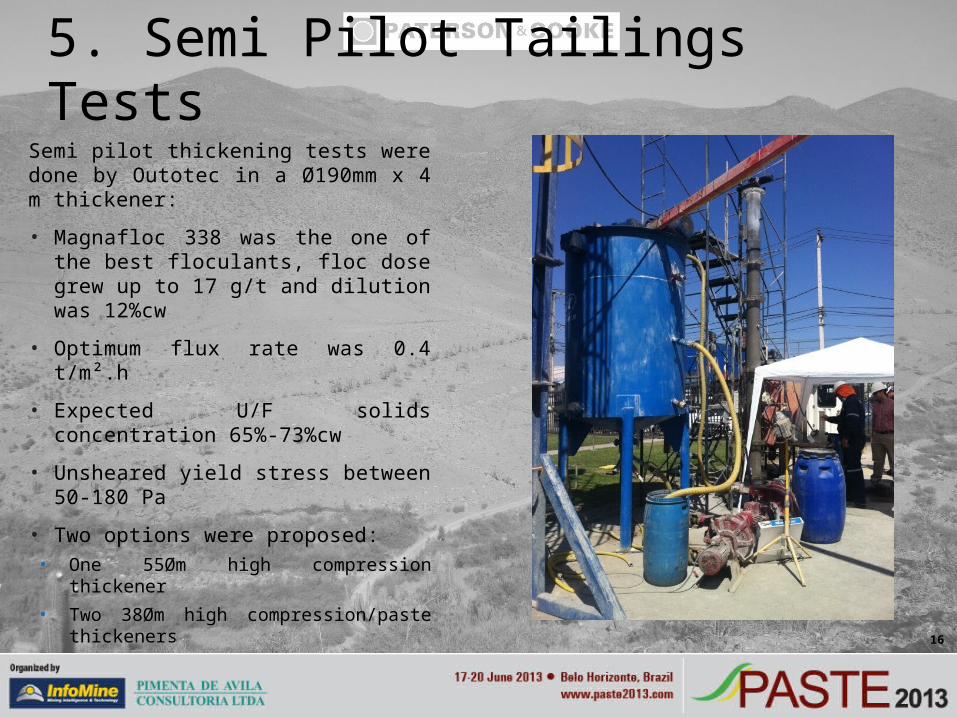
Semi pilot thickening tests were done by Outotec in a Ø190mm x 4 m thickener:
• Magnafloc 338 was the one of the best floculants, floc dose grew up to 17 g/t and dilution was 12%cw
• Optimum flux rate was 0.4 t/m².h
• Expected U/F solids concentration 65%-73%cw
• Unsheared yield stress between 50-180 Pa
• Two options were proposed:• One 55Øm high compression thickener• Two 38Øm high compression/paste
thickeners
5. Semi Pilot Tailings Tests
17
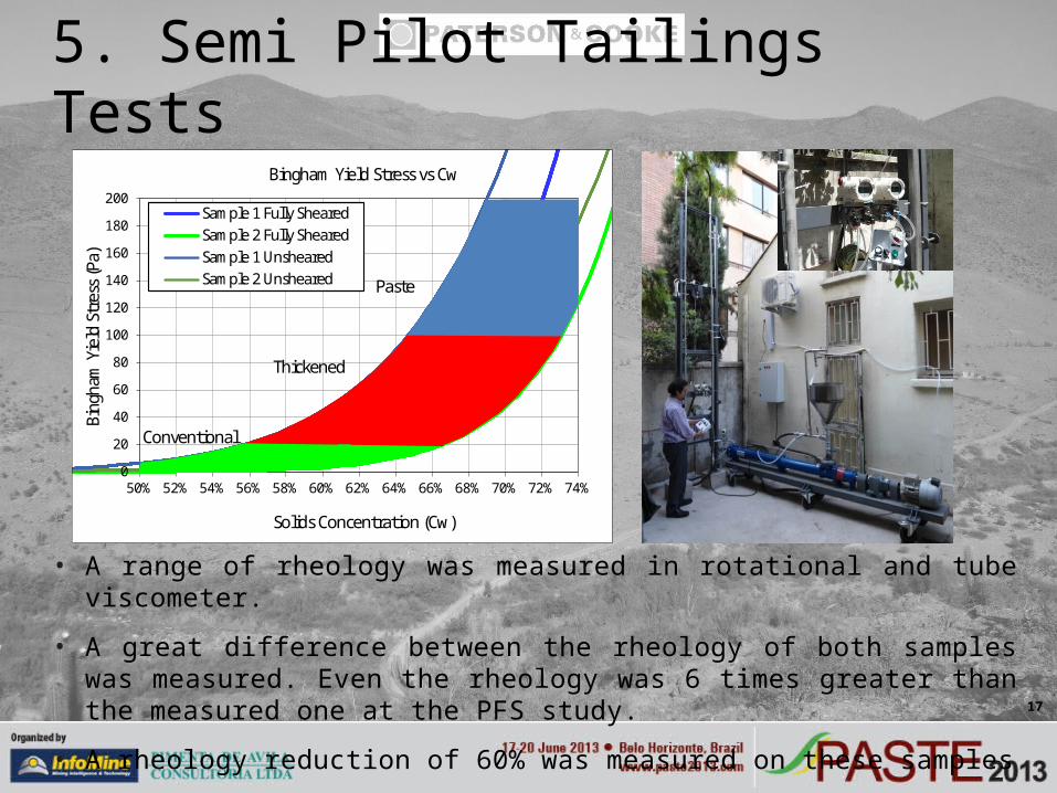
• A range of rheology was measured in rotational and tube viscometer.
• A great difference between the rheology of both samples was measured. Even the rheology was 6 times greater than the measured one at the PFS study.
• A rheology reduction of 60% was measured on these samples
5. Semi Pilot Tailings Tests
0
20
40
60
80
100
120
140
160
180
200
50% 52% 54% 56% 58% 60% 62% 64% 66% 68% 70% 72% 74%
Bing
ham
Yie
ld S
tres
s (P
a)
Solids Concentration (Cw)
Bingham Yield Stress vs Cw
Sample 1 Fully ShearedSample 2 Fully ShearedSample 1 UnshearedSample 2 Unsheared Paste
Thickened
Conventional
18
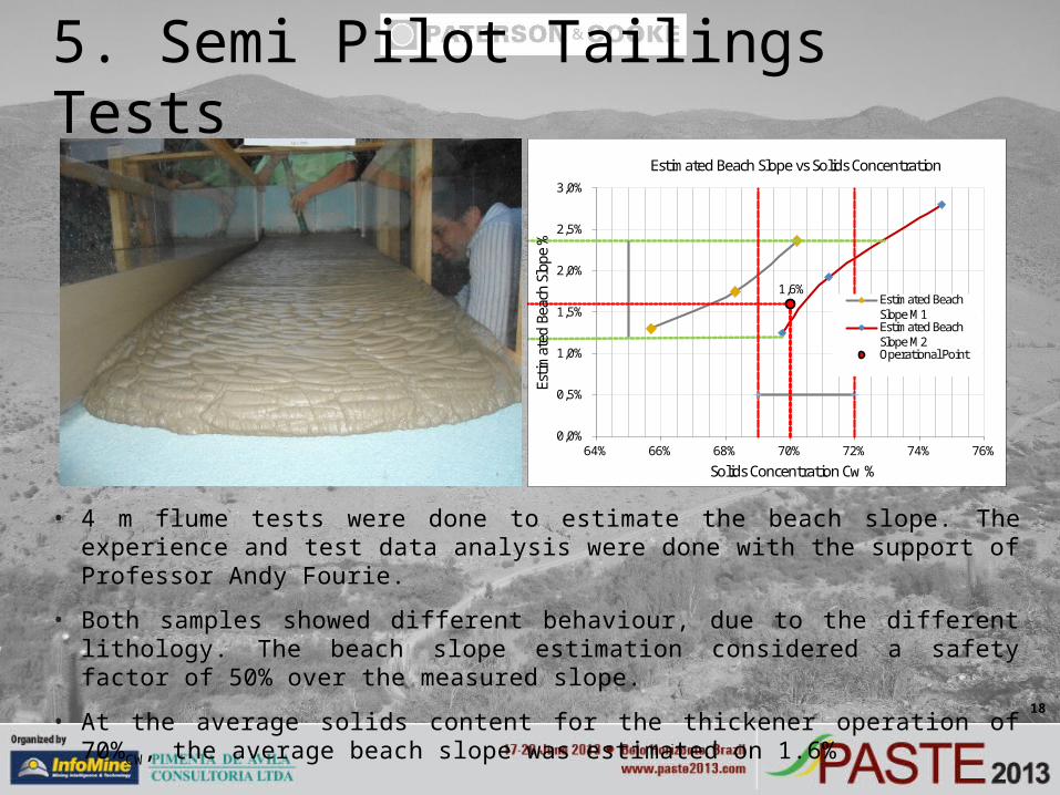
• 4 m flume tests were done to estimate the beach slope. The experience and test data analysis were done with the support of Professor Andy Fourie.
• Both samples showed different behaviour, due to the different lithology. The beach slope estimation considered a safety factor of 50% over the measured slope.
• At the average solids content for the thickener operation of 70%CW, the average beach slope was estimated on 1.6%
5. Semi Pilot Tailings Tests
1,6%
0,0%
0,5%
1,0%
1,5%
2,0%
2,5%
3,0%
64% 66% 68% 70% 72% 74% 76%
Estim
ated
Bea
ch S
lope
%
Solids Concentration Cw %
Estimated Beach Slope vs Solids Concentration
Estimated BeachSlope M1Estimated BeachSlope M2Operational Point
19
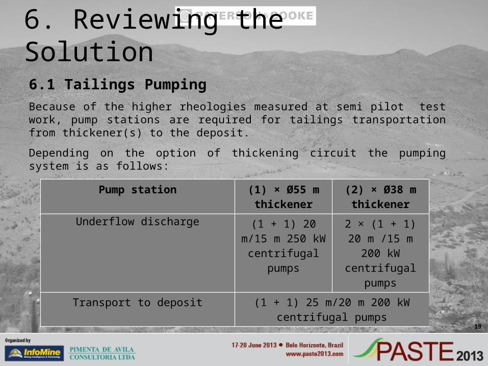
6.1 Tailings PumpingBecause of the higher rheologies measured at semi pilot test work, pump stations are required for tailings transportation from thickener(s) to the deposit.
Depending on the option of thickening circuit the pumping system is as follows:
6. Reviewing the Solution
Pump station (1) × Ø55 m thickener
(2) × Ø38 m thickener
Underflow discharge (1 + 1) 20 m/15 m 250 kW centrifugal
pumps
2 × (1 + 1) 20 m /15 m 200 kW
centrifugal pumps
Transport to deposit (1 + 1) 25 m/20 m 200 kW centrifugal pumps
20
6.2 Filtered tailingsBench top filtering tests were done by Delkor, but the filtration rates were very poor for vacuum and pressure technologies. In spite of those results, an evaluation of filtered tailings system was done.
The area of the deposit is not suitable to dispose tailings in stock piles. This is because of the maximum expected value for the hydrographic basin storm flow which reaches 211 m³/s. As a result, a water dam as well as an evacuation tunnel had to be considered in this evaluation.
Finally the filtered tailings option resulted into a Capex over 2.4 times the thickened tailings option.
6. Reviewing the solution
21
The study developed for this new project of Sociedad Punta del Cobre ended into the following conclusions:
• The site conditions are the most important aspects that define which type of dewatering system is the best. The topography and the hydrographic basin storm determine the design of the deposit and the tailings management system. The other very important aspect are the pumping distances.
• If the material presents good conditions to be thickened or filtrated, a complete test plan must be done to support every engineering evaluation. Bench scale or pilot tests are recommended to be done for each stage of engineering.
• In this case, thickened tailings clearly has technical advantages over conventional and filtered tailings systems. The expected plant make-up water is 0.4 m³/t and the installed power is 2,700 kW
• For feasibility engineering, the final selection of the thickening circuit and the study of disposal strategies will be important issues to address.
7. Conclusion

22
We want to acknowledge to all people who worked with us, from Knight Piesold Chile, Multical, Delkor, Outotec, Mr. Andy Fourie and to Pucobre S.A.
Acknowledgements