Embed Size (px)
Citation preview
Dati TecniciTechnical Data Sheet
19_07_2017
Euro fire
MEFA Italia SpA Fissaggio & Supporto di Impianti Tel. +39 02 93540195 - Fax. +39 02 93543208 - www.mefaitalia.com
Rev. nr. 0
A05
Page/Pagina1 of/di 2
doc. nr. A05001A
Sway Brace Pipe Attachment
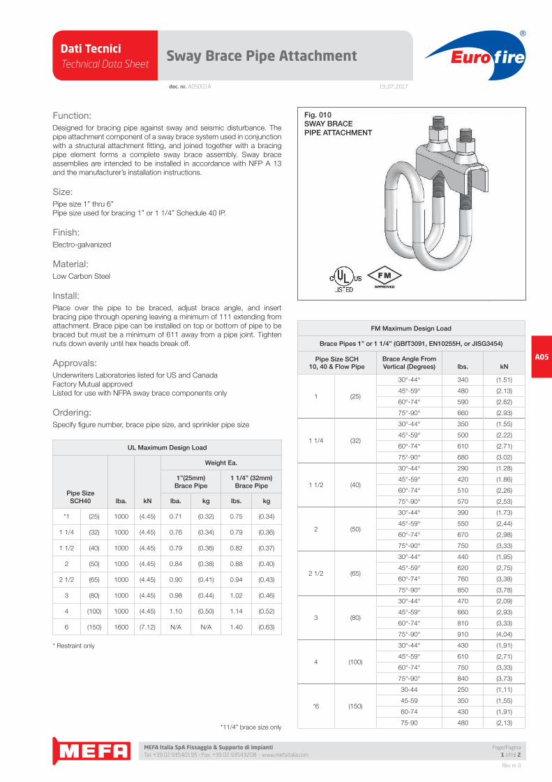
Function:
Designed for bracing pipe against sway and seismic disturbance. The
pipe attachment component of a sway brace system used in conjunction
with a structural attachment fi tting, and joined together with a bracing
pipe element forms a complete sway brace assembly. Sway brace
assemblies are intended to be installed in accordance with NFP A 13
and the manufacturer’s installation instructions.
Size:
Pipe size 1” thru 6”
Pipe size used for bracing 1” or 1 1/4” Schedule 40 IP.
Finish:
Electro-galvanized
Material:
Low Carbon Steel
Install:
Place over the pipe to be braced, adjust brace angle, and insert
bracing pipe through opening leaving a minimum of 111 extending from
attachment. Brace pipe can be installed on top or bottom of pipe to be
braced but must be a minimum of 611 away from a pipe joint. Tighten
nuts down evenly until hex heads break off.
Approvals:
Underwriters Laboratories listed for US and Canada
Factory Mutual approved
Listed for use with NFPA sway brace components only
Ordering:
Specify fi gure number, brace pipe size, and sprinkler pipe size
UL Maximum Design Load
Pipe SizeSCH40 lba. kN
Weight Ea.
1”(25mm)Brace Pipe
1 1/4” (32mm)Brace Pipe
lba. kg lbs. kg
*1 (25) 1000 (4.45) 0.71 (0.32) 0.75 (0.34)
1 1/4 (32) 1000 (4.45) 0.76 (0.34) 0.79 (0.36)
1 1/2 (40) 1000 (4.45) 0.79 (0.36) 0.82 (0.37)
2 (50) 1000 (4.45) 0.84 (0.38) 0.88 (0.40)
2 1/2 (65) 1000 (4.45) 0.90 (0.41) 0.94 (0.43)
3 (80) 1000 (4.45) 0.98 (0.44) 1.02 (0.46)
4 (100) 1000 (4.45) 1.10 (0.50) 1.14 (0.52)
6 (150) 1600 (7.12) N/A N/A 1.40 (0.63)
* Restraint only
FM Maximum Design Load
Brace Pipes 1” or 1 1/4” (GBfT3091, EN10255H, or JISG3454)
Pipe Size SCH 10, 40 & Flow Pipe
Brace Angle From Vertical (Degrees) lbs. kN
1 (25)
30°-44° 340 (1.51)
45°-59° 480 (2.13)
60°-74° 590 (2.62)
75°-90° 660 (2.93)
1 1/4 (32)
30°-44° 350 (1.55)
45°-59° 500 (2.22)
60°-74° 610 (2.71)
75°-90° 680 (3.02)
1 1/2 (40)
30°-44° 290 (1.28)
45°-59° 420 (1.86)
60°-74° 510 (2,26)
75°-90° 570 (2,53)
2 (50)
30°-44° 390 (1.73)
45°-59° 550 (2,44)
60°-74° 670 (2,98)
75°-90° 750 (3,33)
2 1/2 (65)
30°-44° 440 (1,95)
45°-59° 620 (2,75)
60°-74° 760 (3,38)
75°-90° 850 (3,78)
3 (80)
30°-44° 470 (2,09)
45°-59° 660 (2,93)
60°-74° 810 (3,33)
75°-90° 910 (4,04)
4 (100)
30°-44° 430 (1,91)
45°-59° 610 (2,71)
60°-74° 750 (3,33)
75°-90° 840 (3,73)
*6 (150)
30-44 250 (1,11)
45-59 350 (1,55)
60-74 430 (1,91)
75-90 480 (2,13)
Fig. 010SWAY BRACEPIPE ATTACHMENT
*11/4” brace size only
Dati TecniciTechnical Data Sheet
19_07_2017
Euro fire
MEFA Italia SpA Fissaggio & Supporto di Impianti Tel. +39 02 93540195 - Fax. +39 02 93543208 - www.mefaitalia.com
NOTA GENERALE:
L’attrezzatura presentata in questo bollettino deve essere installata in conformità agli ultimi standard pubblicati dalle Norme UNI EN 12845, National Fire Protection Association, Factory Mutual Research Corporation o altre organizzazioni simili e anche con le disposizioni dei codici governativi o delle ordinanze laddove applicabili.Con la presente pagina tecnica, MEFA Italia intende fornire pertinenti informazioni tecniche, aggiornandole periodicamente.MEFA Italia non si ritiene responsabile in caso di errori di stampa o informazioni inesatte in quanto le stesse possono variare senza preavviso.
The equipment presented in this bulletin is to be installed in accordance with the latest published Standards of the UNI EN 12845, National Fire Protection Association, Factory Mutual Research Corporation, or other similar organizations and also with the provisions of governmental codes or ordinances whenever applicable.With this technical page, MEFA Italia intends to provide relevant technical information, updating them periodically.MEFA Italia is not responsible for any inaccurate print or inaccurate information as these may vary without prior notice.
NOTA EUROFIRE:
Eurofi re è un marchio registrato da MEFA Italia per la presentazione di tutti i prodotti della linea Antincendio.I fornitori dei prodotti Eurofi re vengono rigorosamente selezionati nel rispetto della qualità e delle caratteristiche distintive descrittte in questo documento tecnico.I fornitori dei prodotti potrebbero variare senza preavviso, ma sempre nel rispetto delle caratteristiche qui descritte.
Eurofi re is a registered trademark of MEFA Italia for the presentation of all products of the Fire Protection Line.The suppliers of Eurofi re products are strictly selected in compliance with the quality and distinctive features described in this technical document.Product providers may vary without notice, but always respecting the features described herein.
Rev. nr. 0
A05
Page/Pagina2 of/di 2
doc. nr. A05001A
Sway Brace Pipe Attachment
Pipe Braced:
1”, 1 114”, 1 112”, 2”, 2 1/2”, 3”, 4”, 6”
Bracing:
1” Or 1 1/4” SCH40 steel pipe
Function:
Designed for bracing pipe against sway and seismic disturbance. The
pipe attachment component of a sway brace system used in conjunction
with a structural attachment fi tting, and joined together with a bracing
pipe element forms a complete sway brace assembly. Sway brace
assemblies are intended to be installed in accordance with NFPA 13 and
the manufacturer’s installation instructions.
Approvals:
Underwriters Laboratories listed for US and Canada (1” system pipe size
listed as a restraint only) Factory Mutual approved
Listed for use with NFPA sway brace components only
Material:
Low Carbon Steel
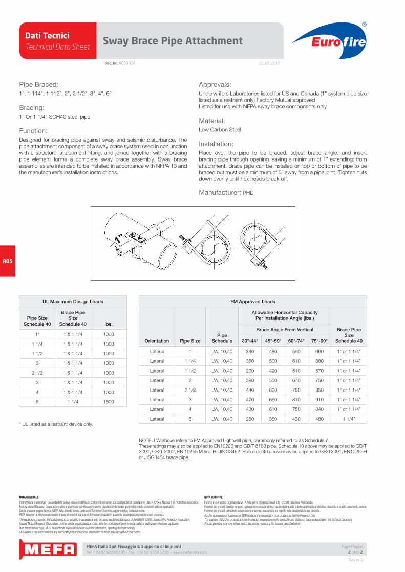
Installation:
Place over the pipe to be braced, adjust brace angle, and insert
bracing pipe through opening leaving a minimum of 1” extending: from
attachment. Brace pipe can be installed on top or bottom of pipe to be
braced but must be a minimum of 6” away from a pipe joint. Tighten nuts
down evenly until hex heads break off.
Manufacturer: PHD
UL Maximum Design Loads
Pipe SizeSchedule 40
Brace PipeSize
Schedule 40 lbs.
1* 1 & 1 1/4 1000
1 1/4 1 & 1 1/4 1000
1 1/2 1 & 1 1/4 1000
2 1 & 1 1/4 1000
2 1/2 1 & 1 1/4 1000
3 1 & 1 1/4 1000
4 1 & 1 1/4 1000
6 1 1/4 1600
FM Approved Loads
Orientation Pipe SizePipe
Schedule
Allowable Horizontal CapacityPer Installation Angle (lbs.)
Brace PipeSize
Schedule 40
Brace Angle From Vertical
30°-44° 45°-59° 60°-74° 75°-90°
Lateral 1 LW, 10,40 340 480 590 660 1” or 1 1/4”
Lateral 1 1/4 LW, 10,40 350 500 610 680 1” or 1 1/4”
Lateral 1 1/2 LW, 10,40 290 420 510 570 1” or 1 1/4”
Lateral 2 LW, 10,40 390 550 670 750 1” or 1 1/4”
Lateral 2 1/2 LW, 10,40 440 620 760 850 1” or 1 1/4”
Lateral 3 LW, 10,40 470 660 810 910 1” or 1 1/4”
Lateral 4 LW, 10,40 430 610 750 840 1” or 1 1/4”
Lateral 6 LW, 10,40 250 350 430 480 1 1/4”* UL listed as a restraint device only.
NOTE: LW above refers to FM Approved Lightwall pipe, commonly referred to as Schedule 7.
These ratings may also be applied to EN10220 and GB/T 8163 pipe. Schedule 10 above may be applied to GB/T
3091, GB/T 3092, EN 10255 M and H, JlS G3452. Schedule 40 above may be applied to GB/T3091, EN10255H
or JISG3454 brace pipe.
Dati TecniciTechnical Data Sheet
19_07_2017
Euro fire
MEFA Italia SpA Fissaggio & Supporto di Impianti Tel. +39 02 93540195 - Fax. +39 02 93543208 - www.mefaitalia.com
Rev. nr. 0
A05
Page/Pagina1 of/di 2
doc. nr. A05002A
Clamping Pipe Attachment
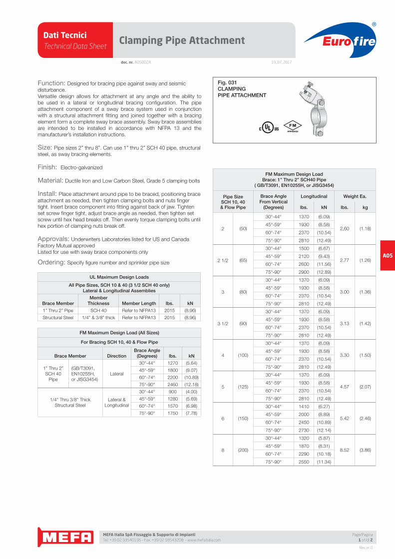
Function: Designed for bracing pipe against sway and seismic
disturbance.
Versatile design allows for attachment at any angle and the ability to
be used in a lateral or longitudinal bracing confi guration. The pipe
attachment component of a sway brace system used in conjunction
with a structural attachment fi tting and joined together with a bracing
element form a complete sway brace assembly. Sway brace assemblies
are intended to be installed in accordance with NFPA 13 and the
manufacturer’s installation instructions.
Size: Pipe sizes 2” thru 8”. Can use 1” thru 2” SCH 40 pipe, structural
steel, as sway bracing elements.
Finish: Electro-galvanized
Material: Ductile Iron and Low Carbon Steel, Grade 5 clamping bolts
Install: Place attachment around pipe to be braced, positioning brace
attachment as needed, then tighten clamping bolts and nuts fi nger
tight. Insert brace component into fi tting against back of jaw. Tighten
set screw fi nger tight, adjust brace angle as needed, then tighten set
screw until hex head breaks off. Then evenly torque clamping bolts until
hex portion of clamping nuts break off.
Approvals: Underwriters Laboratories listed for US and Canada
Factory Mutual approved
Listed for use with sway brace components only
Ordering: Specify fi gure number and sprinkler pipe size
UL Maximum Design Loads
All Pipe Sizes, SCH 10 & 40 (3 1/2 SCH 40 only)Lateral & Longitudinal Assemblies
Brace MemberMember
Thickness Member Length lbs. kN
1” Thru 2” Pipe SCH 40 Refer to NFPA13 2015 (8.96)
Structural Steel 1/4” & 3/8” thick Refer to NFPA13 2015 (8.96)
FM Maximum Design Load (All Sizes)
For Bracing SCH 10, 40 & Flow Pipe
Brace Member DirectionBrace Angle
(Degrees) lbs. kN
1” Thru 2”
SCH 40
Pipe
(GB/T3091,
EN10255H,
or JISG3454)
Lateral
30°-44° 1270 (5.64)
45°-59° 1800 (9.07)
60°-74° 2200 (10.89)
75°-90° 2460 (12.18)
1/4” Thru 3/8” Thick
Structural Steel
Lateral &
Longitudinal
30°-44° 900 (4.00)
45°-59° 1280 (5.69)
60°-74° 1570 (6.98)
75°-90° 1750 (7.78)
FM Maximum Design LoadBrace: 1” Thru 2” SCH40 Pipe
( GB/T3091, EN10255H, or JISG3454)
Pipe SizeSCH 10, 40& Flow Pipe
Brace AngleFrom Vertical
(Degrees)
Longitudinal Weight Ea.
lbs. kN lbs. kg
2 (50)
30°-44° 1370 (6.09)
2,60 (1.18)45°-59° 1930 (8.58)
60°-74° 2370 (10.54)
75°-90° 2810 (12.49)
2 1/2 (65)
30°-44° 1500 (6.67)
2.77 (1.26)45°-59° 2120 (9.43)
60°-74° 2600 (11.56)
75°-90° 2900 (12.89)
3 (80)
30°-44° 1370 (6.09)
3.00 (1.36)45°-59° 1930 (8.58)
60°-74° 2370 (10.54)
75°-90° 2810 (12.49)
3 1/2 (90)
30°-44° 1370 (6.09)
3.13 (1.42)45°-59° 1930 (8.58)
60°-74° 2370 (10.54)
75°-90° 2810 (12.49)
4 (100)
30°-44° 1370 (6.09)
3.30 (1.50)45°-59° 1930 (8.58)
60°-74° 2370 (10.54)
75°-90° 2810 (12.49)
5 (125)
30°-44° 1370 (6.09)
4.57 (2.07)45°-59° 1930 (8.58)
60°-74° 2370 (10.54)
75°-90° 2810 (12.49)
6 (150)
30°-44° 1410 (6.27)
5.42 (2.46)45°-59° 2000 (8.89)
60°-74° 2450 (10.89)
75°-90° 2730 (12.14)
8 (200)
30°-44° 1320 (5.87)
8.52 (3.86)45°-59° 1870 (8.31)
60°-74° 2290 (10.18)
75°-90° 2550 (11.34)
Fig. 031CLAMPINGPIPE ATTACHMENT
Dati TecniciTechnical Data Sheet
19_07_2017
Euro fire
MEFA Italia SpA Fissaggio & Supporto di Impianti Tel. +39 02 93540195 - Fax. +39 02 93543208 - www.mefaitalia.com
NOTA GENERALE:
L’attrezzatura presentata in questo bollettino deve essere installata in conformità agli ultimi standard pubblicati dalle Norme UNI EN 12845, National Fire Protection Association, Factory Mutual Research Corporation o altre organizzazioni simili e anche con le disposizioni dei codici governativi o delle ordinanze laddove applicabili.Con la presente pagina tecnica, MEFA Italia intende fornire pertinenti informazioni tecniche, aggiornandole periodicamente.MEFA Italia non si ritiene responsabile in caso di errori di stampa o informazioni inesatte in quanto le stesse possono variare senza preavviso.
The equipment presented in this bulletin is to be installed in accordance with the latest published Standards of the UNI EN 12845, National Fire Protection Association, Factory Mutual Research Corporation, or other similar organizations and also with the provisions of governmental codes or ordinances whenever applicable.With this technical page, MEFA Italia intends to provide relevant technical information, updating them periodically.MEFA Italia is not responsible for any inaccurate print or inaccurate information as these may vary without prior notice.
NOTA EUROFIRE:
Eurofi re è un marchio registrato da MEFA Italia per la presentazione di tutti i prodotti della linea Antincendio.I fornitori dei prodotti Eurofi re vengono rigorosamente selezionati nel rispetto della qualità e delle caratteristiche distintive descrittte in questo documento tecnico.I fornitori dei prodotti potrebbero variare senza preavviso, ma sempre nel rispetto delle caratteristiche qui descritte.
Eurofi re is a registered trademark of MEFA Italia for the presentation of all products of the Fire Protection Line.The suppliers of Eurofi re products are strictly selected in compliance with the quality and distinctive features described in this technical document.Product providers may vary without notice, but always respecting the features described herein.
Rev. nr. 0
A05
Page/Pagina2 of/di 2
doc. nr. A05002A
Clamping Pipe Attachment
Pipe Braced:
2”, 2 1/2”, 3”, 3 1/2”, 4”, 5”, 6”, 8”
Bracing:
1” thru 2” SCH 40 pipe, structural steel
Function:
Designed for bracing pipe against sway and seismic disturbance. Versatile
design allows for attachment at any angle and the ability to be used
in a lateral or longitudinal bracing confi guration. The pipe attachment
component of a sway brace system used in conjunction with a structural
attachment fi tting and joined together with a bracing element forming a
complete sway brace assembly. Sway brace assemblies are intended
to be installed in accordance with NFPA 13 and the manufacturer’s
installation instructions.
Approvals:
Underwriters Laboratories listed for US and Canada
Factory Mutual approved
Listed for use with sway brace components only
Material:
Ductile Iron and Low Carbon Steel, Grade 5 clamping bolts
Installation:
Place attachment around pipe to be braced, positioning brace
attachment as needed, then tighten clamping bolts and nuts fi nger
tight. Insert brace component into fi tting against back of jaw. Tighten set
screw fi nger tight, adjust brace angle as needed, then tighten set screw
until hex head breaks off. Then evenly torque clamping bolts until hex
portion of clamping nuts break off.
Manufacturer: PHD
UL Maximum Design Loads
Pipe Sizes 2” thru 8” SCH 10 & 40 (3 1/2 SCH 40 only)Lateral & Longitudinal Assemblies
Brace MemberMember
Thickness Member LengthMax. Design
Load
1” Thru 2” Pipe SCH 40 Refer to NFPA13 2015
Structural Steel 1/4” to 3/8” thick Refer to NFPA13 2015
FM Maximum Design Loads
Orientation Pipe Size PipeSchedule
Allowable Horizontal CapacityPer Installation Angle (lbs.)
BraceMemberBrace Angle From Vertical
30°-44° 45°-59° 60°-74° 75°-90°
Lateral 2, 2 1/2, 3, 3 1/2, 4, 5, 6, 8 LW, 10, 40 1270 1800 2200 2460 1” to 2” Schedule 40 Pipe
Longitudinal 2 LW, 10, 40 1370 1930 2370 2810 1” to 2” Schedule 40 Pipe
Longitudinal 2 1/2 LW, 10, 40 1500 2120 2600 2900 1” to 2” Schedule 40 Pipe
Longitudinal 3, 3 1/2, 4 LW, 10, 40 1370 1930 2370 2810 1” to 2” Schedule 40 Pipe
Longitudinal 5, 6 LW, 10, 40 1410 2000 2450 2730 1” to 2” Schedule 40 Pipe
Longitudinal 8 LW, 10, 40 1320 1870 2290 2550 1” to 2” Schedule 40 Pipe
Lateral or Longitudinal 2, 2 1/2, 3, 3 1/2, 4, 5, 6, 8 LW, 10, 40 900 1280 1570 1750 1/4” to 3/8” Thick Structural Steel
NOTE: LW above refers to FM Approved Lightwall pipe, commonly referred to as Schedule 7. These ratings may also be applied to EN10220 and GB/T 8163 pipe. Schedule
10 above may be applied to GB/T 3091, GB/T 3092, EN 10255 M and H, JIS G3452. Schedule 40 above may be applied to GB/T3091, EN10255H or JISG3454 brace pipe.
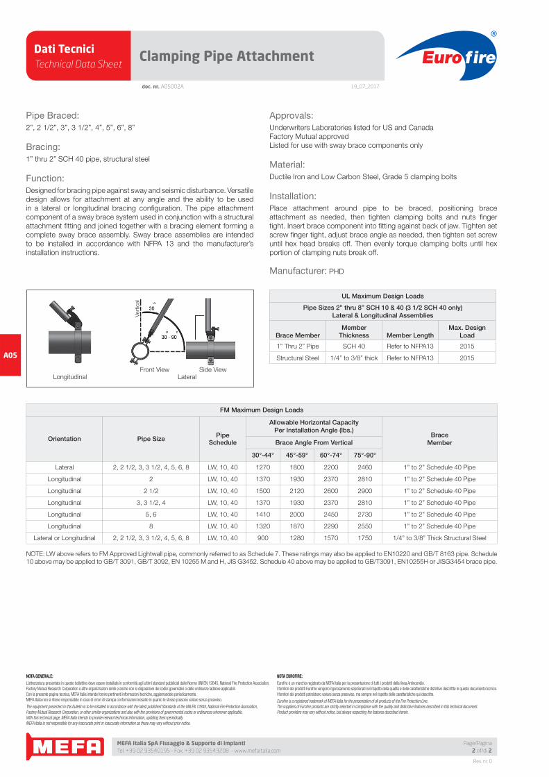
LongitudinalFront View
LateralSide View
Vert
ical
Dati TecniciTechnical Data Sheet
19_07_2017
Euro fire
MEFA Italia SpA Fissaggio & Supporto di Impianti Tel. +39 02 93540195 - Fax. +39 02 93543208 - www.mefaitalia.com
Rev. nr. 0
A05
Page/Pagina1 of/di 2
doc. nr. A05003A
Supporting Pipe Attachment
Function:
Designed for bracing pipe against sway and seismic disturbance.
Versatile design allows for attachment at any angle and the ability to
be used in a lateral or longitudinal bracing confi guration. The pipe
attachment component of a sway brace system used in conjunction
with two structural attachment fi ttings and joined together with a bracing
element form a complete sway brace assembly. Sway brace assemblies
are intended to be installed in accordance with NFPA 13 and the
manufacturer’s installation instructions.
Size:
Pipe sizes 2” thru 8”. Refer to Structural attachment fi tting literature
regarding appropriate brace members, sizes, and further loading limitations.
Finish: Electro-galvanized
Material: Low Carbon Steel, Grade 5 clamping bolts
Install:
Attach structural attachment fi tting, Fig. 030 (sold separately), to Fig.
040 using supplied fastener. Place the assembly around the pipe to
be braced, positioning welded clevis on top of the pipe, then tighten
clamping bolts and nuts fi nger tight. Follow structural attachment fi tting’s
instructions for attaching to brace element. Adjust the brace element to
the desired angle then tighten the supplied fastener to lock the structural
attachment fi tting, Fig. 030, securely in position with the Fig. 040. Then
evenly torque clamping bolts until hex portion of clamping nuts break off.
Approvals:
Underwriters Laboratories listed for US and Canada as a hanger or as
a sway brace
Factory Mutual approved as a sway brace only
Listed for use with sway brace components only
Ordering: Specify fi gure number and sprinkler pipe size
UL Maximum Design Load
Pipe SizeSCH 10 & 40
HangerRod Size
Rec. Max.HangerLoad
Max. DesignSway Brace
LoadWeight Ea.
lbs. kN lbs. kN lbs. kN
2 (50) 3/8 (10) 730 (3.25) 1000 (4.45) 2.40 (1.09)
2 1/2 (65) 1/2 (12) 850 (3.78) 1000 (4.45) 2.58 (1.17)
3 (80) 1/2 (12) 1000 (4.45) 1000 (4.45) 2.80 (1.27)
*3 1/2 (90) 1/2 (12) 1000 (4.45) 1000 (4.45) 2.94 (1.33)
4 (100) 5/8 (16) 1000 (4.45) 1000 (4.45) 3.28 (1.49)
5 (125) 5/8 (16) 1600 (7.12) 1600 (7.12) 4.95 (2.25)
6 (150) 3/4 (20) 1600 (7.12) 1600 (7.12) 6.93 (3.14)
8 (200) 3/4 (20) 2015 (8.96) 2015 (8.96) 9.97 (4.52)
* SCH 40 only
FM Maximum Design Load
Pipe Size SCH 10, 40
& Flow Pipe
Brace Angle From
Vertical(Degrees)
Lateral Longitudinal
lbs. kN lbs. kN
2 (50)
30°-44° 1070 (4.75) 1260 (5.60)
45°-59° 1520 (6.76) 1440 (6.40)
60°-74° 1860 (8.27) 1740 (7.73)
75°-90° 2080 (9.25) 1940 (8.62)
2 1/2 (65)
30°-44° 960 (4.27) 1000 (4.44)
45°-59° 1360 (6.04) 1420 (6.31)
60°-74° 1670 (7.42) 1740 (7.73)
75°-90° 1860 (8.27) 1940 (8.62)
3 (80)
30°-44° 960 (4.27) 1000 (4.44)
45°-59° 1360 (6.04) 1420 (6.31)
60°-74° 1670 (7.42) 1740 (7.73)
75°-90° 1860 (8.27) 1940 (8.62)
3 1/2 (90)
30°-44° 960 (4.27) 1000 (4.44)
45°-59° 1360 (6.04) 1420 (6.31)
60°-74° 1670 (7.42) 1740 (7.73)
75°-90° 1860 (8.27) 1940 (8.62)
4 (100)
30°-44° 960 (4.27) 1110 (4.93)
45°-59° 1360 (6.04) 1490 (6.62)
60°-74° 1670 (7.42) 1800 (8.00)
75°-90° 1860 (8.27) 1920 (8.54)
5 (125)
30°-44° 960 (4.27) 1110 (4.93)
45°-59° 1360 (6.04) 1490 (6.62)
60°-74° 1670 (7.42) 1800 (8.00)
75°-90° 1860 (8.27) 1920 (8.54)
6 (150)
30°-44° 1000 (4.44) 1280 (5.69)
45°-59° 1420 (6.31) 1810 (8.05)
60°-74° 1740 (7.73) 2210 (9.83)
75°-90° 1940 (8.62) 2470 (10.98)
8 (200)
30°-44° 1350 (6.00) 1160 (5.15)
45°-59° 1900 (8.45) 1650 (7.33)
60°-74° 2330 (10.36) 2020 (8.98)
75°-90° 2600 11.56) 2250 (10.00)
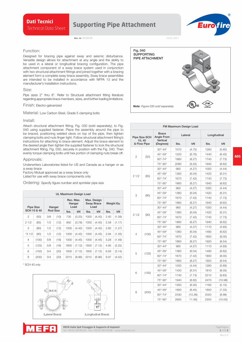
Fig. 040SUPPORTINGPIPE ATTACHMENT
Note: Figure 030 sold separately.
(Lateral Brace) (Longitudinal Brace)
Dati TecniciTechnical Data Sheet
19_07_2017
Euro fire
MEFA Italia SpA Fissaggio & Supporto di Impianti Tel. +39 02 93540195 - Fax. +39 02 93543208 - www.mefaitalia.com
NOTA GENERALE:
L’attrezzatura presentata in questo bollettino deve essere installata in conformità agli ultimi standard pubblicati dalle Norme UNI EN 12845, National Fire Protection Association, Factory Mutual Research Corporation o altre organizzazioni simili e anche con le disposizioni dei codici governativi o delle ordinanze laddove applicabili.Con la presente pagina tecnica, MEFA Italia intende fornire pertinenti informazioni tecniche, aggiornandole periodicamente.MEFA Italia non si ritiene responsabile in caso di errori di stampa o informazioni inesatte in quanto le stesse possono variare senza preavviso.
The equipment presented in this bulletin is to be installed in accordance with the latest published Standards of the UNI EN 12845, National Fire Protection Association, Factory Mutual Research Corporation, or other similar organizations and also with the provisions of governmental codes or ordinances whenever applicable.With this technical page, MEFA Italia intends to provide relevant technical information, updating them periodically.MEFA Italia is not responsible for any inaccurate print or inaccurate information as these may vary without prior notice.
NOTA EUROFIRE:
Eurofi re è un marchio registrato da MEFA Italia per la presentazione di tutti i prodotti della linea Antincendio.I fornitori dei prodotti Eurofi re vengono rigorosamente selezionati nel rispetto della qualità e delle caratteristiche distintive descrittte in questo documento tecnico.I fornitori dei prodotti potrebbero variare senza preavviso, ma sempre nel rispetto delle caratteristiche qui descritte.
Eurofi re is a registered trademark of MEFA Italia for the presentation of all products of the Fire Protection Line.The suppliers of Eurofi re products are strictly selected in compliance with the quality and distinctive features described in this technical document.Product providers may vary without notice, but always respecting the features described herein.
Rev. nr. 0
A05
Page/Pagina2 of/di 2
doc. nr. A05003A
Supporting Pipe Attachment
Pipe Braced:
2”, 2 1/2”, 3”, 3 1/2”, 4”, 5”, 6”, 8”
Bracing:
Refer to attachment fi tting literature regarding appropriate brace
members, sizes, and further loading limitations.
Function:
Designed for bracing pipe against sway and seismic disturbance.
Versatile design allows for attachment at any angle and the ability to
be used in a lateral or longitudinal bracing confi guration. The pipe
attachment component of a sway brace system used in conjunction
with two structural attachment fi ttings and joined together with a bracing
element form a complete sway brace assembly. Sway brace assemblies
are intended to be installed in accordance with NFPA 13 and the
manufacturer’s installation instructions.
Approvals:
Underwriters Laboratories listed for US and Canada as a hanger or as
a sway brace
Factory Mutual approved as a sway brace only
Listed for use with sway brace components only
Material:
Low Carbon Steel, Grade 5 clamping bolts
Installation:
Attach structural attachment fi tting, Fig. 030 (sold separately), to Fig.
040 using supplied fastener. Place the assembly around the pipe to
be braced, positioning welded clevis on top of the pipe, then tighten
clamping bolts and nuts fi nger tight. Follow structural attachment fi tting’s
instructions for attaching to brace element. Adjust the brace element to
the desired angle then tighten the supplied fastener to lock the structural
attachment fi tting, Fig. 030, securely in position with the Fig. 040. Then
evenly torque clamping bolts until hex portion of clamping nuts break off.
Manufacturer: PHD
UL Maximum Design Loads
Pipe Sizes 2” Thru 8” SCH 10 & 40 (3 1/2 SCH 40 only)
Lateral & Longitudinal Assemblies
PipeSize
RodSize
HangerUsed with
threaded rod
Sway BraceUsed with Fig. 030
lbs. lbs.
2 3/8 730 1000
2 1/2 1/2 850 1000
3 1/2 1000 1000
3 1/2 1/2 1000 1000
4 5/8 1000 1000
5 5/8 1600 1600
6 3/4 1600 1600
8 3/4 2015 2015
FM Maximum Design Loads
Orientation Pipe SizePipe
Schedule
Allowable Horizontal CapacityPer Installation Angle (lbs.)
Brace Angle From Vertical
30°-44° 45°-59° 60°-74° 75°-90°
Lateral 2 LW, 10, 40 1070 1520 1860 2080
Lateral 2 1/2, 3, 3 1/2, 4, 5 LW, 10, 40 960 1360 1670 1860
Lateral 6 LW, 10, 40 1000 1420 1740 1940
Lateral 8 LW, 10, 40 1350 1900 2330 2600
Longitudinal 2 LW, 10, 40 1260 1440 1740 1940
Longitudinal 2 1/2, 3, 3 1/2 LW, 10, 40 1000 1420 1740 1940
Longitudinal 4, 5 LW, 10, 40 1110 1490 1800 1920
Longitudinal 6 LW, 10, 40 1280 1810 2210 2470
Longitudinal 8 LW, 10, 40 1160 1650 2020 2250
NOTE: LW above refers to FM Approved Lightwall pipe, commonly referred to as Schedule 7. These ratings may
also be applied to EN10220 and GB/T 8163 pipe. Schedule 10 above may be applied to GB/T 3091, GB/T 3092,
EN 10255 M and H, JIS G3452. Schedule 40 above may be applied to GB/T3091, EN10255H or JISG3454
brace pipe.
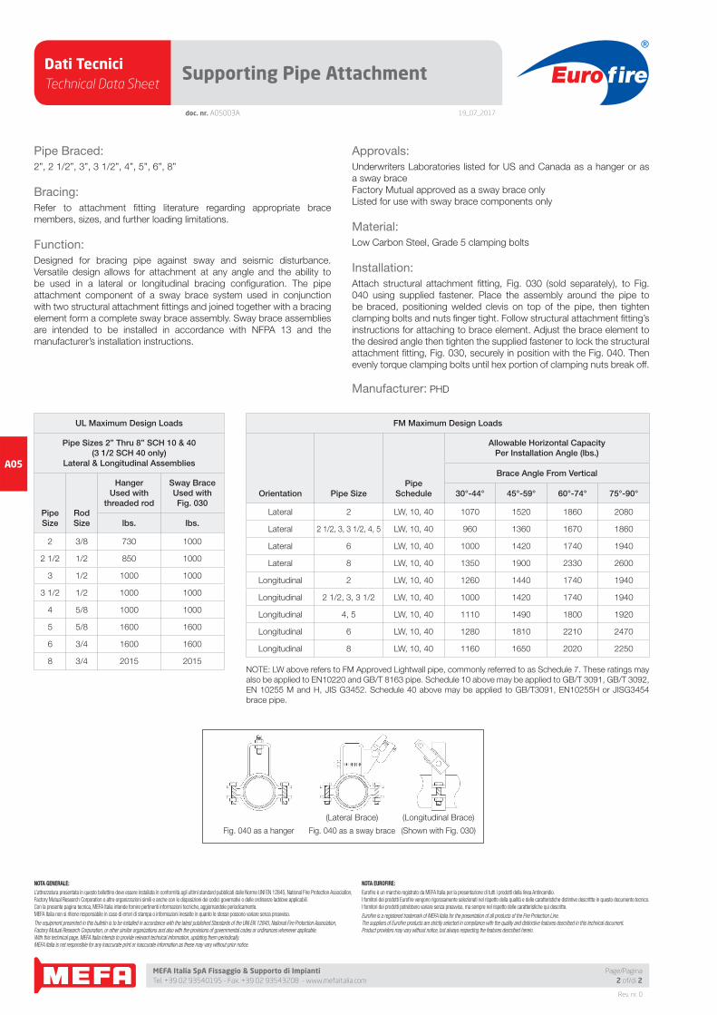
(Lateral Brace)
Fig. 040 as a sway braceFig. 040 as a hanger
(Longitudinal Brace)
(Shown with Fig. 030)
Dati TecniciTechnical Data Sheet
19_07_2017
Euro fire
MEFA Italia SpA Fissaggio & Supporto di Impianti Tel. +39 02 93540195 - Fax. +39 02 93543208 - www.mefaitalia.com
Rev. nr. 0
A05
Page/Pagina1 of/di 2
doc. nr. A05004A
C-Clamp Structural Attachment
Function:
Designed for bracing pipe against sway and seismic disturbances.
Universal swivel design allows for attachment at any surface angle
combined with concentric loading. Structure attachment fi tting designed
to use 1” thru 2” SCH 40 pipe, structural steel, as sway bracing elements.
No bracing member thicker than 3/8” can be used in conjunction with
this product. Utilize the Fig. 030 with a pipe attachment fi tting and a
bracing element to form a complete sway brace assembly. Sway brace
assemblies are intended to be installed in accordance with NFPA 13 and
the manufacturer’s installation instructions.
Size:
1/2” mounting hole
Braces up to 8” Pipe MAX
Finish:
Electro-galvanized
Material:
Ductile Iron and Low Carbon Steel
Install:
Mount device to structure then insert brace element into fi tting against
back of jaw. Tighten set screw fi nger tight, then tighten until hex head
breaks off. Adjust attachment to proper brace angle.
Approvals:
Underwriters Laboratories listed for US and Canada
Factory Mutual approved
Listed for use with NFPA fastener tables and sway brace components
only
Ordering: Specify fi gure number
UL Maximum Design Loads (Up to 8” Pipe)Lateral & Longitudinal Assemblies
Brace Member
MemberThickness
Member Length
lbs. kNWeight Ea.
lbs. kN
1” Thru 2” Pipe SCH 40 Refer to NFPA13 2015 (8.96)1.46 (0.66)
Structural Steel 3/8” thick MAX Refer to NFPA13 2015 (8.96)
FM Maximum Design LoadFor Bracing SCH 10, 40 & Flow Pipe
BraceMember
Brace AngleFrom Vertical
(Degrees) lbs. kN
1” Thru 2”
SCH 40 Pipe
(GB/T3091,
EN10255H,
or JISG3454)
30°-44° 1270 (5.64)
45°-59° 2040 (9.07)
60°-74° 2450 (10.89)
75°-90° 2740 (12.18)
1/4” Thru 3/8” Thick
Structural Steel
30°-44° 900 (4.00)
45°-59° 1280 (5.69)
60°-74° 1570 (6.98)
75°-90° 1750 (7.78)
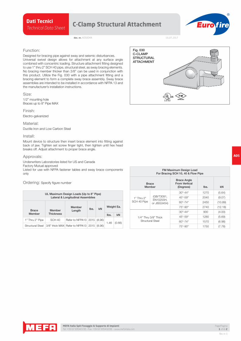
Fig. 030C-CLAMPSTRUCTURALATTACHMENT
Dati TecniciTechnical Data Sheet
19_07_2017
Euro fire
MEFA Italia SpA Fissaggio & Supporto di Impianti Tel. +39 02 93540195 - Fax. +39 02 93543208 - www.mefaitalia.com
NOTA GENERALE:
L’attrezzatura presentata in questo bollettino deve essere installata in conformità agli ultimi standard pubblicati dalle Norme UNI EN 12845, National Fire Protection Association, Factory Mutual Research Corporation o altre organizzazioni simili e anche con le disposizioni dei codici governativi o delle ordinanze laddove applicabili.Con la presente pagina tecnica, MEFA Italia intende fornire pertinenti informazioni tecniche, aggiornandole periodicamente.MEFA Italia non si ritiene responsabile in caso di errori di stampa o informazioni inesatte in quanto le stesse possono variare senza preavviso.
The equipment presented in this bulletin is to be installed in accordance with the latest published Standards of the UNI EN 12845, National Fire Protection Association, Factory Mutual Research Corporation, or other similar organizations and also with the provisions of governmental codes or ordinances whenever applicable.With this technical page, MEFA Italia intends to provide relevant technical information, updating them periodically.MEFA Italia is not responsible for any inaccurate print or inaccurate information as these may vary without prior notice.
NOTA EUROFIRE:
Eurofi re è un marchio registrato da MEFA Italia per la presentazione di tutti i prodotti della linea Antincendio.I fornitori dei prodotti Eurofi re vengono rigorosamente selezionati nel rispetto della qualità e delle caratteristiche distintive descrittte in questo documento tecnico.I fornitori dei prodotti potrebbero variare senza preavviso, ma sempre nel rispetto delle caratteristiche qui descritte.
Eurofi re is a registered trademark of MEFA Italia for the presentation of all products of the Fire Protection Line.The suppliers of Eurofi re products are strictly selected in compliance with the quality and distinctive features described in this technical document.Product providers may vary without notice, but always respecting the features described herein.
Rev. nr. 0
A05
Page/Pagina2 of/di 2
doc. nr. A05004A
C-Clamp Structural Attachment
Pipe Braced:
8” Pipe MAX
Bracing:
1” thru 2” SCH 40 pipe, structural steel
Function:
Designed for bracing pipe against sway and seismic disturbances.
Universal swivel design allows for attachment at any surface angle
combined with concentric loading. Structure attachment fi tting designed
to use 1” thru 2” SCH 40 pipe, structural steel, as sway bracing elements.
No bracing member thicker than 3/8” can be used in conjunction with
this product. Utilize the Fig. 030 with a pipe attachment fi tting and a
bracing element to form a complete sway brace assembly. Sway brace
assemblies are intended to be installed in accordance with NFPA 13 and
the manufacturer’s installation instructions.
Approvals:
Underwriters Laboratories listed for US and Canada
Factory Mutual approved
Listed for use with NFPA13 fastener tables and sway brace components
only
Material:
Ductile Iron and Low Carbon Steel
Installation:
Mount device to structure then insert brace element into fi tting against
back of jaw. Tighten set screw fi nger tight, then tighten until hex head
breaks off. Adjust attachment to proper brace angle.
Manufacturer: PHD
UL Maximum Design Loads (Up to 8” Pipe)
Brace MemberMember
Thickness Member Length lbs.
1” Thru 2” Pipe SCH 40 Refer to NFPA13 2015
NFPA13 Structural Steel 3/8” thick MAX Refer to NFPA13 2015
FM Maximum Design Load
For Bracing SCH 10, 40 & Flow Pipe
BraceMember
Brace AngleFrom Vertical
(Degrees) lbs.
1” Thru 2”
SCH 40 Pipe
(GB/T3091,
EN10255H,
or JISG3454)
30°-44° 1270
45°-59° 2040
60°-74° 2450
75°-90° 2740
1/4” Thru 3/8” Thick
Structural Steel
30°-44° 900
45°-59° 1280
60°-74° 1570
75°-90° 1750
Dati TecniciTechnical Data Sheet
19_07_2017
Euro fire
MEFA Italia SpA Fissaggio & Supporto di Impianti Tel. +39 02 93540195 - Fax. +39 02 93543208 - www.mefaitalia.com
Rev. nr. 0
A05
Page/Pagina1 of/di 1
doc. nr. A05005A
Multi-Fastener Adapter
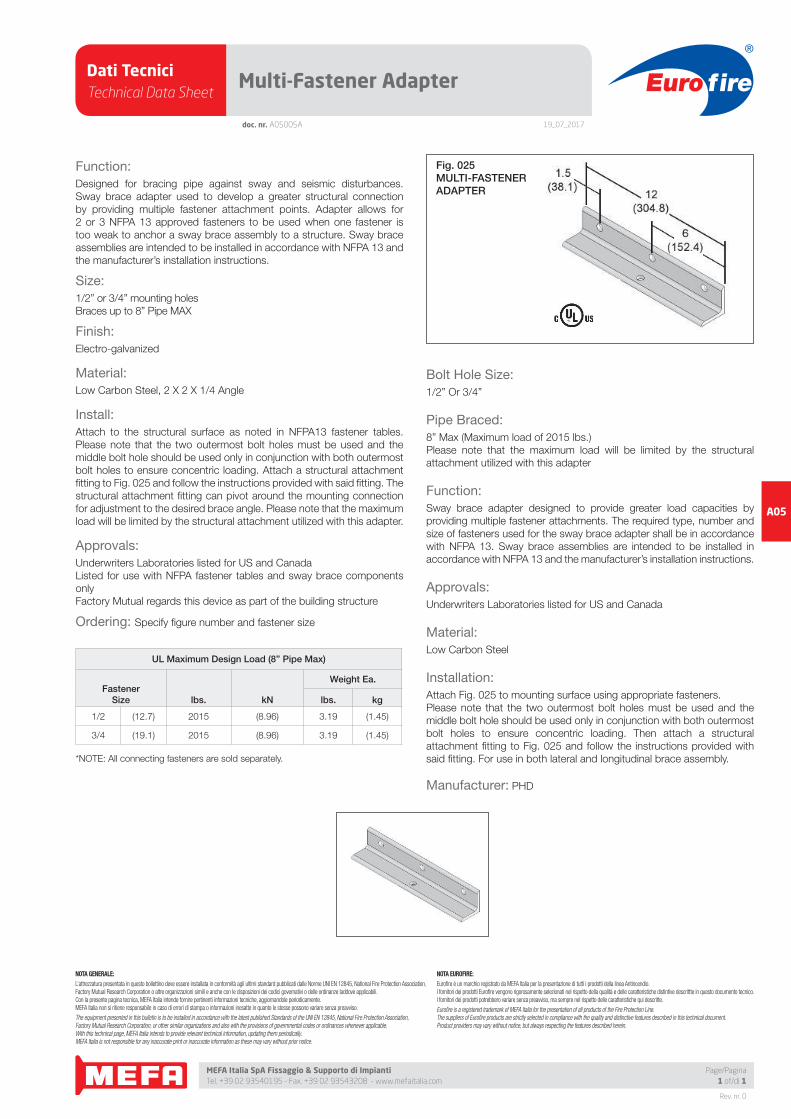
Function:
Designed for bracing pipe against sway and seismic disturbances.
Sway brace adapter used to develop a greater structural connection
by providing multiple fastener attachment points. Adapter allows for
2 or 3 NFPA 13 approved fasteners to be used when one fastener is
too weak to anchor a sway brace assembly to a structure. Sway brace
assemblies are intended to be installed in accordance with NFPA 13 and
the manufacturer’s installation instructions.
Size:
1/2” or 3/4” mounting holes
Braces up to 8” Pipe MAX
Finish:
Electro-galvanized
Material:
Low Carbon Steel, 2 X 2 X 1/4 Angle
Install:
Attach to the structural surface as noted in NFPA13 fastener tables.
Please note that the two outermost bolt holes must be used and the
middle bolt hole should be used only in conjunction with both outermost
bolt holes to ensure concentric loading. Attach a structural attachment
fi tting to Fig. 025 and follow the instructions provided with said fi tting. The
structural attachment fi tting can pivot around the mounting connection
for adjustment to the desired brace angle. Please note that the maximum
load will be limited by the structural attachment utilized with this adapter.
Approvals:
Underwriters Laboratories listed for US and Canada
Listed for use with NFPA fastener tables and sway brace components
only
Factory Mutual regards this device as part of the building structure
Ordering: Specify fi gure number and fastener size
UL Maximum Design Load (8” Pipe Max)
FastenerSize lbs. kN
Weight Ea.
lbs. kg
1/2 (12.7) 2015 (8.96) 3.19 (1.45)
3/4 (19.1) 2015 (8.96) 3.19 (1.45)
*NOTE: All connecting fasteners are sold separately.
Fig. 025MULTI-FASTENERADAPTER
Bolt Hole Size:
1/2” Or 3/4”
Pipe Braced:
8” Max (Maximum load of 2015 lbs.)
Please note that the maximum load will be limited by the structural
attachment utilized with this adapter
Function:
Sway brace adapter designed to provide greater load capacities by
providing multiple fastener attachments. The required type, number and
size of fasteners used for the sway brace adapter shall be in accordance
with NFPA 13. Sway brace assemblies are intended to be installed in
accordance with NFPA 13 and the manufacturer’s installation instructions.
Approvals:
Underwriters Laboratories listed for US and Canada
Material:
Low Carbon Steel
Installation:
Attach Fig. 025 to mounting surface using appropriate fasteners.
Please note that the two outermost bolt holes must be used and the
middle bolt hole should be used only in conjunction with both outermost
bolt holes to ensure concentric loading. Then attach a structural
attachment fi tting to Fig. 025 and follow the instructions provided with
said fi tting. For use in both lateral and longitudinal brace assembly.
Manufacturer: PHD
NOTA GENERALE:
L’attrezzatura presentata in questo bollettino deve essere installata in conformità agli ultimi standard pubblicati dalle Norme UNI EN 12845, National Fire Protection Association, Factory Mutual Research Corporation o altre organizzazioni simili e anche con le disposizioni dei codici governativi o delle ordinanze laddove applicabili.Con la presente pagina tecnica, MEFA Italia intende fornire pertinenti informazioni tecniche, aggiornandole periodicamente.MEFA Italia non si ritiene responsabile in caso di errori di stampa o informazioni inesatte in quanto le stesse possono variare senza preavviso.
The equipment presented in this bulletin is to be installed in accordance with the latest published Standards of the UNI EN 12845, National Fire Protection Association, Factory Mutual Research Corporation, or other similar organizations and also with the provisions of governmental codes or ordinances whenever applicable.With this technical page, MEFA Italia intends to provide relevant technical information, updating them periodically.MEFA Italia is not responsible for any inaccurate print or inaccurate information as these may vary without prior notice.
NOTA EUROFIRE:
Eurofi re è un marchio registrato da MEFA Italia per la presentazione di tutti i prodotti della linea Antincendio.I fornitori dei prodotti Eurofi re vengono rigorosamente selezionati nel rispetto della qualità e delle caratteristiche distintive descrittte in questo documento tecnico.I fornitori dei prodotti potrebbero variare senza preavviso, ma sempre nel rispetto delle caratteristiche qui descritte.
Eurofi re is a registered trademark of MEFA Italia for the presentation of all products of the Fire Protection Line.The suppliers of Eurofi re products are strictly selected in compliance with the quality and distinctive features described in this technical document.Product providers may vary without notice, but always respecting the features described herein.
Dati TecniciTechnical Data Sheet
19_07_2017
Euro fire
MEFA Italia SpA Fissaggio & Supporto di Impianti Tel. +39 02 93540195 - Fax. +39 02 93543208 - www.mefaitalia.com
Rev. nr. 0
A05
Page/Pagina1 of/di 2
doc. nr. A05006A
Sway Brace Bar Joist Adapter
Function:
Sway brace adapter used to attach a sway brace assembly to a steel bar
joist or structural member of 3/8” maximum thickness. To provide a point
of connection when drilling or welding is not allowed or not practical.
Sway brace assemblies are intended to be installed in accordance with
NFPA 13 and the manufacturer’s installation instructions.
Size:
Braces up to 8” Pipe MAX
Attaches to 3/8” thick MAX structural members
When attaching to a structure thicker than 3/8”, please see Fig. 045.
Finish:
Electro-galvanized
Material:
Ductile Iron
Install:
Steel bar joist manufacturer’s warranty requires attachment within 6”of
chord panel point. Place on structural member with the fl ange contacting
the back of the jaw. Tighten set screws fi nger tight, then evenly tighten
until hex heads break off. Attach structural attachment to Fig. 035 with
the supplied attachment bolt, ensuring that the attachment bolt head
bottoms out securely. Please note that the maximum load will be limited
by the structural attachment utilized with this adapter.
Approvals:
Underwriters Laboratories listed for US and Canada
Factory Mutual approved
Listed for use with NFPA fastener tables and sway brace components only
Ordering: Specify fi gure number
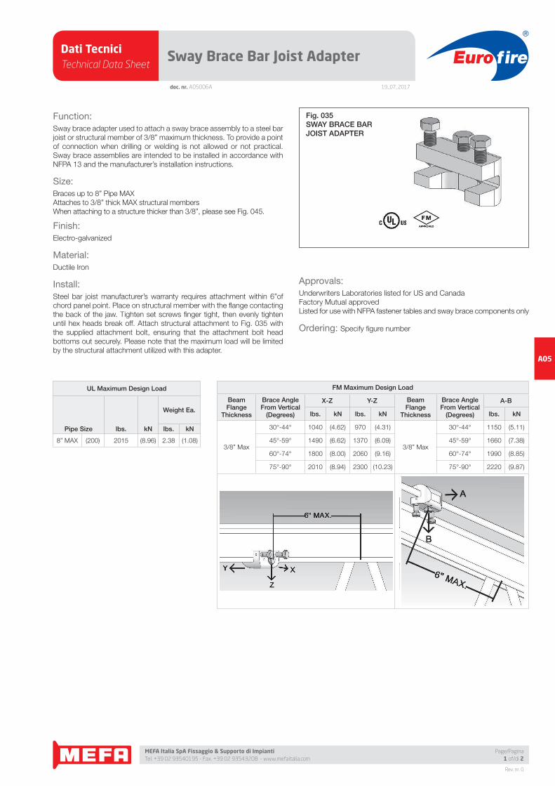
Fig. 035SWAY BRACE BARJOIST ADAPTER
FM Maximum Design Load
BeamFlange
Thickness
Brace AngleFrom Vertical
(Degrees)
X-Z Y-Z BeamFlange
Thickness
Brace AngleFrom Vertical
(Degrees)
A-B
lbs. kN lbs. kN lbs. kN
3/8” Max
30°-44° 1040 (4.62) 970 (4.31)
3/8” Max
30°-44° 1150 (5.11)
45°-59° 1490 (6.62) 1370 (6.09) 45°-59° 1660 (7.38)
60°-74° 1800 (8.00) 2060 (9.16) 60°-74° 1990 (8.85)
75°-90° 2010 (8.94) 2300 (10.23) 75°-90° 2220 (9.87)
UL Maximum Design Load
Pipe Size lbs. kN
Weight Ea.
lbs. kN
8” MAX (200) 2015 (8.96) 2.38 (1.08)
Dati TecniciTechnical Data Sheet
19_07_2017
Euro fire
MEFA Italia SpA Fissaggio & Supporto di Impianti Tel. +39 02 93540195 - Fax. +39 02 93543208 - www.mefaitalia.com
NOTA GENERALE:
L’attrezzatura presentata in questo bollettino deve essere installata in conformità agli ultimi standard pubblicati dalle Norme UNI EN 12845, National Fire Protection Association, Factory Mutual Research Corporation o altre organizzazioni simili e anche con le disposizioni dei codici governativi o delle ordinanze laddove applicabili.Con la presente pagina tecnica, MEFA Italia intende fornire pertinenti informazioni tecniche, aggiornandole periodicamente.MEFA Italia non si ritiene responsabile in caso di errori di stampa o informazioni inesatte in quanto le stesse possono variare senza preavviso.
The equipment presented in this bulletin is to be installed in accordance with the latest published Standards of the UNI EN 12845, National Fire Protection Association, Factory Mutual Research Corporation, or other similar organizations and also with the provisions of governmental codes or ordinances whenever applicable.With this technical page, MEFA Italia intends to provide relevant technical information, updating them periodically.MEFA Italia is not responsible for any inaccurate print or inaccurate information as these may vary without prior notice.
NOTA EUROFIRE:
Eurofi re è un marchio registrato da MEFA Italia per la presentazione di tutti i prodotti della linea Antincendio.I fornitori dei prodotti Eurofi re vengono rigorosamente selezionati nel rispetto della qualità e delle caratteristiche distintive descrittte in questo documento tecnico.I fornitori dei prodotti potrebbero variare senza preavviso, ma sempre nel rispetto delle caratteristiche qui descritte.
Eurofi re is a registered trademark of MEFA Italia for the presentation of all products of the Fire Protection Line.The suppliers of Eurofi re products are strictly selected in compliance with the quality and distinctive features described in this technical document.Product providers may vary without notice, but always respecting the features described herein.
Rev. nr. 0
A05
Page/Pagina2 of/di 2
doc. nr. A05006A
Sway Brace Bar Joist Adapter
Pipe Braced:
8” Pipe MAX
Function:
Sway brace adapter used to attach a sway brace assembly to a steel bar
joist or structural member of 3/8” maximum thickness. To provide a point
of connection when drilling or welding is not allowed or not practical.
Sway brace assemblies are intended to be installed in accordance with
NFPA 13 and the manufacturer’s installation instructions.
Approvals:
Underwriters Laboratories listed for US and Canada
Factory Mutual approved
Listed for use with NFPA fastener tables and sway brace components
only
Material:
Ductile Iron
Installation:
Steel bar joist manufacturer’s warranty requires attachment within 6”of
chord panel point. Place on structural member with the fl ange contacting
the back of the jaw. Tighten set screws fi nger tight, then evenly tighten
until hex heads break off. Attach structural attachment to Fig. 035 with
the supplied attachment bolt, ensuring that the attachment bolt head
bottoms out securely.
Please note that the maximum load will be limited by the structural
attachment utilized with this adapter.
Manufacturer: PHD
UL Maximum Design Load
Pipe Size lbs.
8” MAX 2015
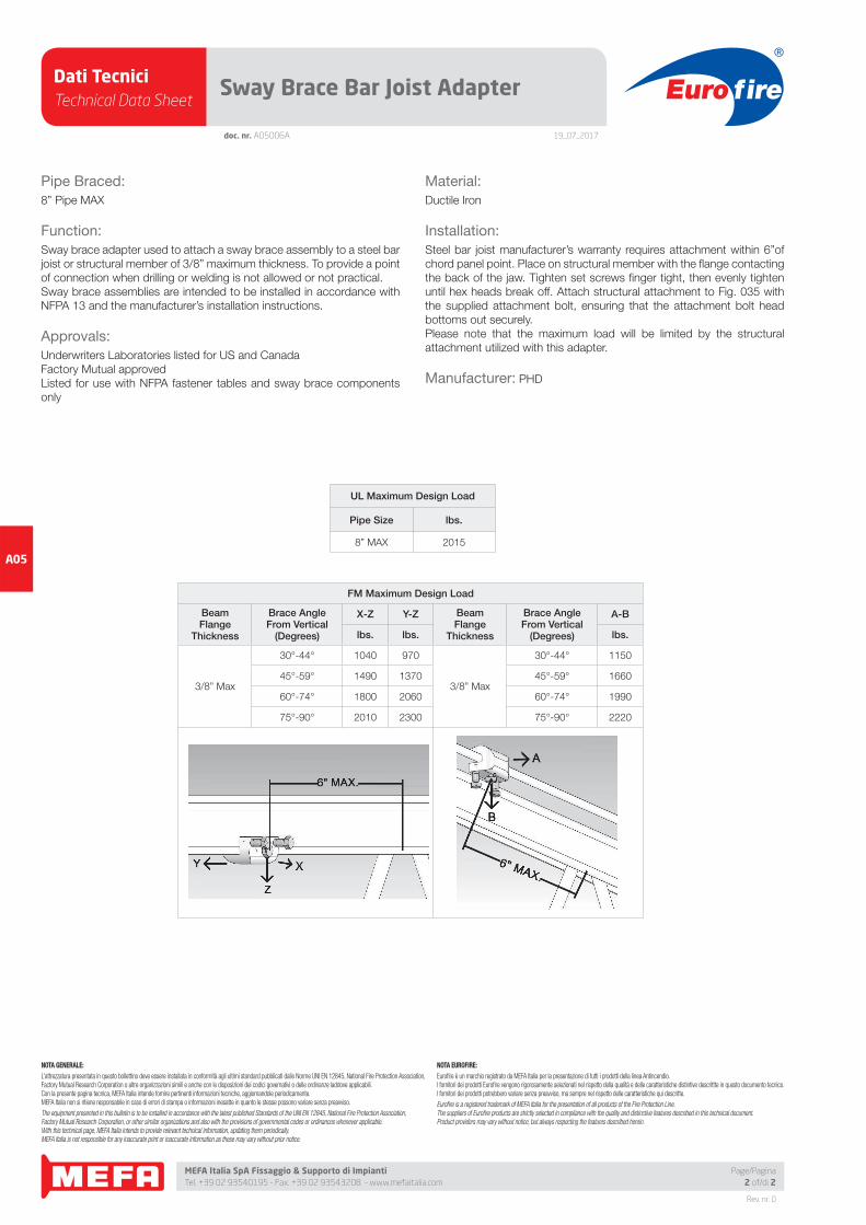
FM Maximum Design Load
BeamFlange
Thickness
Brace AngleFrom Vertical
(Degrees)
X-Z Y-Z BeamFlange
Thickness
Brace AngleFrom Vertical
(Degrees)
A-B
lbs. lbs. lbs.
3/8” Max
30°-44° 1040 970
3/8” Max
30°-44° 1150
45°-59° 1490 1370 45°-59° 1660
60°-74° 1800 2060 60°-74° 1990
75°-90° 2010 2300 75°-90° 2220
Dati TecniciTechnical Data Sheet
19_07_2017
Euro fire
MEFA Italia SpA Fissaggio & Supporto di Impianti Tel. +39 02 93540195 - Fax. +39 02 93543208 - www.mefaitalia.com
Rev. nr. 0
A05
Page/Pagina1 of/di 2
doc. nr. A05007A
Sway Brace Structural Adapter
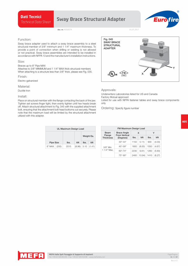
Function:
Sway brace adapter used to attach a sway brace assembly to a steel
structural member of 3/8” minimum and 1 1/4” maximum thickness. To
provide a point of connection when drilling or welding is not allowed
or not practical. Sway brace assemblies are intended to be installed in
accordance with NFPA 13 and the manufacturer’s installation instructions.
Size:
Braces up to 8” Pipe MAX
Attaches to 3/8” MINIMUM and 1 1/4” MAX thick structural members
When attaching to a structure less than 3/8” thick, please see Fig. 035.
Finish:
Electro-galvanized
Material:
Ductile Iron
Install:
Place on structural member with the fl ange contacting the back of the jaw.
Tighten set screws fi nger tight, then evenly tighten until hex heads break
off. Attach structural attachment to Fig. 045 with the supplied attachment
bolt, ensuring that the attachment bolt head bottoms out securely. Please
note that the maximum load will be limited by the structural attachment
utilized with this adapter.
Approvals:
Underwriters Laboratories listed for US and Canada
Factory Mutual approved
Listed for use with NFPA fastener tables and sway brace components
only
Ordering: Specify fi gure number
Fig. 045SWAY BRACESTRUCTURALADAPTER
FM Maximum Design Load
BeamFlange
Thickness
Brace AngleFrom Vertical
(Degrees)
X Y
lbs. kN lbs. kN
3/8” Min.
1 1/4” Max.
30°-44° 1150 5.11) 900 (4.00)
45°-59° 1800 (8.00) 1050 (4.67)
60°-74° 2230 9.91) 1260 (5.60)
75°-90° 2460 10.94) 1410 (6.27)
UL Maximum Design Load
Pipe Size lbs. kN
Weight Ea.
lbs. kN
8” MAX (200) 2015 (8.96) 3.10 (1.41)
Dati TecniciTechnical Data Sheet
19_07_2017
Euro fire
MEFA Italia SpA Fissaggio & Supporto di Impianti Tel. +39 02 93540195 - Fax. +39 02 93543208 - www.mefaitalia.com
NOTA GENERALE:
L’attrezzatura presentata in questo bollettino deve essere installata in conformità agli ultimi standard pubblicati dalle Norme UNI EN 12845, National Fire Protection Association, Factory Mutual Research Corporation o altre organizzazioni simili e anche con le disposizioni dei codici governativi o delle ordinanze laddove applicabili.Con la presente pagina tecnica, MEFA Italia intende fornire pertinenti informazioni tecniche, aggiornandole periodicamente.MEFA Italia non si ritiene responsabile in caso di errori di stampa o informazioni inesatte in quanto le stesse possono variare senza preavviso.
The equipment presented in this bulletin is to be installed in accordance with the latest published Standards of the UNI EN 12845, National Fire Protection Association, Factory Mutual Research Corporation, or other similar organizations and also with the provisions of governmental codes or ordinances whenever applicable.With this technical page, MEFA Italia intends to provide relevant technical information, updating them periodically.MEFA Italia is not responsible for any inaccurate print or inaccurate information as these may vary without prior notice.
NOTA EUROFIRE:
Eurofi re è un marchio registrato da MEFA Italia per la presentazione di tutti i prodotti della linea Antincendio.I fornitori dei prodotti Eurofi re vengono rigorosamente selezionati nel rispetto della qualità e delle caratteristiche distintive descrittte in questo documento tecnico.I fornitori dei prodotti potrebbero variare senza preavviso, ma sempre nel rispetto delle caratteristiche qui descritte.
Eurofi re is a registered trademark of MEFA Italia for the presentation of all products of the Fire Protection Line.The suppliers of Eurofi re products are strictly selected in compliance with the quality and distinctive features described in this technical document.Product providers may vary without notice, but always respecting the features described herein.
Rev. nr. 0
A05
Page/Pagina2 of/di 2
doc. nr. A05007A
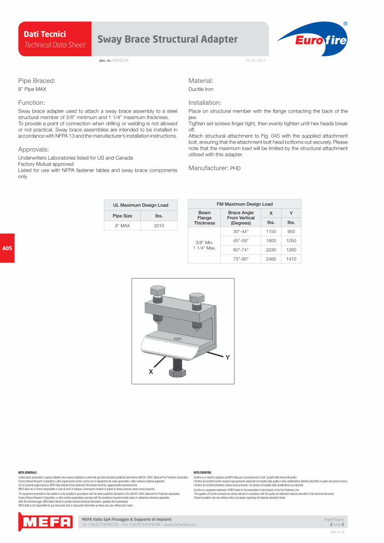
Sway Brace Structural Adapter
Pipe Braced:
8” Pipe MAX
Function:
Sway brace adapter used to attach a sway brace assembly to a steel
structural member of 3/8” minimum and 1 1/4” maximum thickness.
To provide a point of connection when drilling or welding is not allowed
or not practical. Sway brace assemblies are intended to be installed in
accordance with NFPA 13 and the manufacturer’s installation instructions.
Approvals:
Underwriters Laboratories listed for US and Canada
Factory Mutual approved
Listed for use with NFPA fastener tables and sway brace components
only
Material:
Ductile Iron
Installation:
Place on structural member with the fl ange contacting the back of the
jaw.
Tighten set screws fi nger tight, then evenly tighten until hex heads break
off.
Attach structural attachment to Fig. 045 with the supplied attachment
bolt, ensuring that the attachment bolt head bottoms out securely. Please
note that the maximum load will be limited by the structural attachment
utilized with this adapter.
Manufacturer: PHD
UL Maximum Design Load
Pipe Size lbs.
8” MAX 2015
FM Maximum Design Load
BeamFlange
Thickness
Brace AngleFrom Vertical
(Degrees)
X Y
lbs. lbs.
3/8” Min.
1 1/4” Max.
30°-44° 1150 900
45°-59° 1800 1050
60°-74° 2230 1260
75°-90° 2460 1410