Embed Size (px)
DESCRIPTION
data sheet for on delay timer
Citation preview
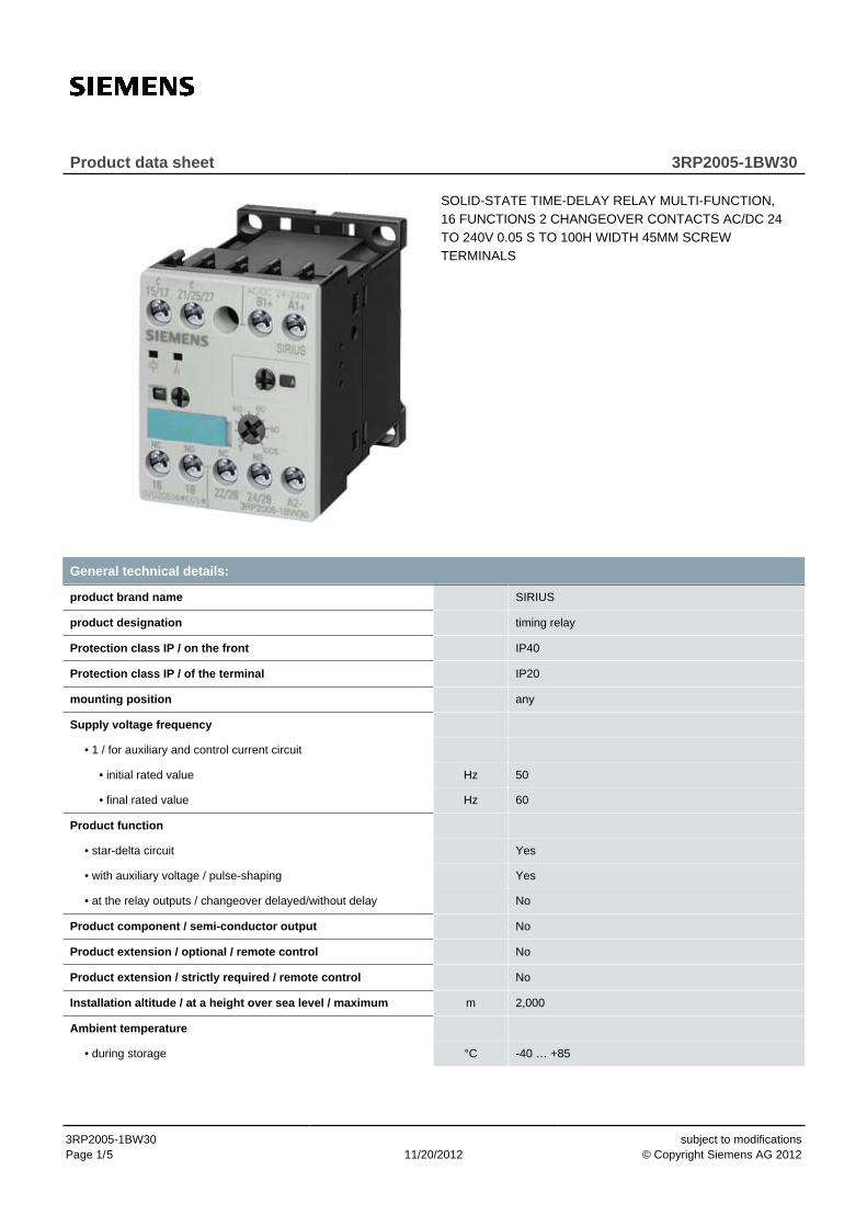
Product data sheet 3RP2005-1BW30
SOLID-STATE TIME-DELAY RELAY MULTI-FUNCTION,16 FUNCTIONS 2 CHANGEOVER CONTACTS AC/DC 24TO 240V 0.05 S TO 100H WIDTH 45MM SCREWTERMINALS
General technical details:
product brand name SIRIUS
product designation timing relay
Protection class IP / on the front IP40
Protection class IP / of the terminal IP20
mounting position any
Supply voltage frequency
• 1 / for auxiliary and control current circuit
• initial rated value Hz 50
• final rated value Hz 60
Product function
• star-delta circuit Yes
• with auxiliary voltage / pulse-shaping Yes
• at the relay outputs / changeover delayed/without delay No
Product component / semi-conductor output No
Product extension / optional / remote control No
Product extension / strictly required / remote control No
Installation altitude / at a height over sea level / maximum m 2,000
Ambient temperature
• during storage °C -40 … +85
3RP2005-1BW30Page 1/ 11/20/2012
subject to modifications© Copyright Siemens AG 20125
• during operating °C -25 … +60
• during transport °C -40 … +85
Relative humidity
• during operating phase % 15 … 70
2 kV network connection / 1 kV control connection
Conductor-bound parasitic coupling conductor-earth SURGE /according to IEC 61000-4-5
2 kV
Conductor-bound parasitic coupling conductor-conductorSURGE / according to IEC 61000-4-5
1 kV
Electrostatic discharge / according to IEC 61000-4-2 4 kV contact discharge / 8 kV air discharge
Field-bound parasitic coupling / according to IEC 61000-4-3 10 V/m
Resistance against vibration 10 ... 55 Hz / 0.35 mm
Impulse voltage resistance / rated value V 4,000
Insulation voltage / rated value V 300
Active power loss / total / typical W 2
Item designation / according to DIN 40719 extendable after IEC204-2 / according to IEC 750
K
Item designation / according to DIN EN 61346-2 K
Category / according to EN 954-1 none
Protection against electrical shock finger-safe
Switching Function:
Switching function
• slow-operating Yes
• making pulse contact No
• firmly clocked beginning with pulse No
• firmly clocked beginning with pause Yes
• relapse delayed Yes
• variably clocked start with impulse No
• impuls variably clocked start with pause No
• with auxiliary voltage
• in an additive way slow-operating Yes
• temporary line fault Yes
• relapse delayed Yes
• without auxiliary voltage / relapse delayed No
• slow-operating/instantaneous contact Yes
• with auxiliary voltage
• relapse delayed/instantaneous contact Yes
• slow-operating/relapse delayed/instantaneous contact Yes
• firmly clocked beginning with pause/instantaneous contact Yes
• making pulse contact/instantaneous contact Yes
3RP2005-1BW30Page 2/ 11/20/2012
subject to modifications© Copyright Siemens AG 20125
• with auxiliary voltage
• temporary line fault/instantaneous contact Yes
• pulse modelling/instantaneous contact Yes
• slow-operating/instantaneous contact Yes
General details:
Type of voltage / of the controlled supply voltage AC/DC
Control supply voltage frequency
• 1 Hz 50 … 60
Control supply voltage
• 1
• at 50 Hz
• for AC V 24 … 240
• at 60 Hz
• for AC V 24 … 240
• for DC V 24 … 240
Operating range factor control supply voltage rated value
• at 50 Hz
• for AC 0.8 … 1.1
• at 60 Hz
• for AC 0.8 … 1.1
• for DC 0.85 … 1.1
Auxiliary circuit:
Operating current / of auxiliary contacts
• as normally closed contact / for AC-15
• at 24 V A 3
• at 250 V A 3
• as normally open contact / for AC-15
• at 24 V A 3
• at 250 V A 3
• at AC-15
• maximum A 3
• at DC-13
• at 24 V A 1
• at 125 V A 0.2
• at 250 V A 0.1
Number of NC contacts / delayed switching 0
Number of NC contacts / non-delayed 0
Number of NO contacts / delayed switching 0
3RP2005-1BW30Page 3/ 11/20/2012
subject to modifications© Copyright Siemens AG 20125

Number of NO contacts / non-delayed 0
Number of change-over switches / delayed switching 2
Number of change-over switches / non-delayed 0
Short-circuit:
Design of the fuse link / for short-circuit protection of theauxiliary switch / required
fuse gL/gG: 4 A
Type of mounting screw and snap-on mounting onto 35 mm standardmounting rail
Installation/mounting/dimensions:
Width mm 45
Height mm 57
Depth mm 73
Distance, to be maintained, to the ranks assembly
• upwards mm 0
• forwards mm 0
• sidewards mm 0
• backwards mm 0
• downwards mm 0
Distance, to be maintained, to earthed part
• backwards mm 0
• sidewards mm 0
• upwards mm 0
• forwards mm 0
• downwards mm 0
Distance, to be maintained, conductive elements
• downwards mm 0
• backwards mm 0
• sidewards mm 0
• forwards mm 0
• upwards mm 0
Connections:
Design of the snap-on socket base none
Design of the electrical connection
• jumper socket No
• for auxiliary and control current circuit screw-type terminals
Type of the connectable conductor cross-section / for AWGconductors / for auxiliary contacts
2x (20 ... 16)
AWG number / as coded connectable conductor cross-section /for auxiliary contact
3RP2005-1BW30Page 4/ 11/20/2012
subject to modifications© Copyright Siemens AG 20125

• minimum 20
• maximum 16
Certificates/approvals:
Verification of suitability CE / UL / CSA
General Product Approval EMC Declaration ofConformity
Test Certificates
Special TestCertificate
Shipping Approval
Shipping Approval other
EnvironmentalConfirmations
Further information:
Information- and Downloadcenter (Catalogs, Brochures,…)http://www.siemens.com/industrial-controls/catalogs
Industry Mall (Online ordering system)http://www.siemens.com/industrial-controls/mall
CAx-Online-Generatorhttp://www.siemens.com/cax
Service&Support (Manuals, Certificates, Characteristics, FAQs,...)http://support.automation.siemens.com/WW/view/en/3RP2005-1BW30/all
Image database (product images, 2D dimension drawings, 3D models, device circuit diagrams, ...)http://www.automation.siemens.com/bilddb/cax_en.aspx?mlfb=3RP2005-1BW30
last change: Sep 10, 2012
3RP2005-1BW30Page 5/ 11/20/2012
subject to modifications© Copyright Siemens AG 20125