Embed Size (px)
Citation preview
�ABB
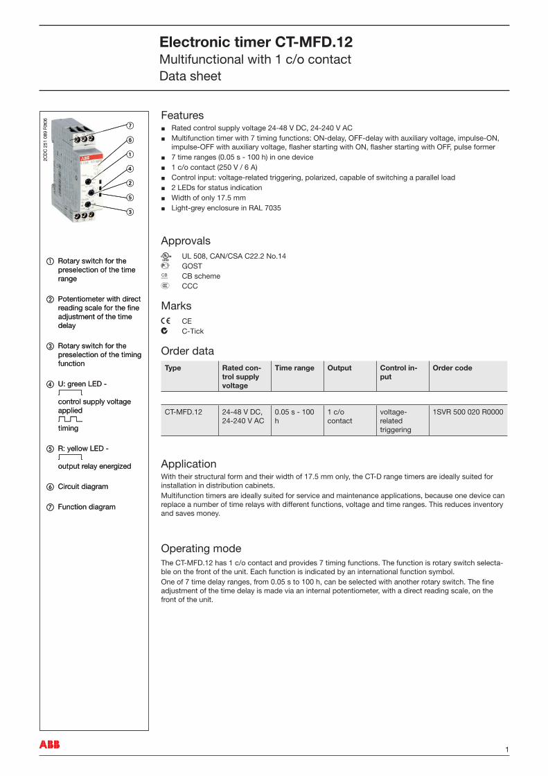
FeaturesRated control supply voltage 24‑48 V DC, 24‑240 V ACMultifunction timer with 7 timing functions: ON‑delay, OFF‑delay with auxiliary voltage, impulse‑ON, impulse‑OFF with auxiliary voltage, flasher starting with ON, flasher starting with OFF, pulse former7 time ranges (0.05 s ‑ �00 h) in one device� c/o contact (250 V / 6 A)Control input: voltage‑related triggering, polarized, capable of switching a parallel load2 LEDs for status indicationWidth of only �7.5 mmLight‑grey enclosure in RAL 7035
ApprovalsA UL 508, CAN/CSA C22.2 No.�4D GOSTK CB schemeE CCC
Marksa CEb C‑Tick
Order dataType Rated con-
trol supply voltage
Time range Output Control in-put
Order code
CT‑MFD.�2 24‑48 V DC, 24‑240 V AC
0.05 s ‑ �00 h
� c/o contact
voltage‑ related triggering
�SVR 500 020 R0000
ApplicationWith their structural form and their width of �7.5 mm only, the CT‑D range timers are ideally suited for installation in distribution cabinets. Multifunction timers are ideally suited for service and maintenance applications, because one device can replace a number of time relays with different functions, voltage and time ranges. This reduces inventory and saves money.
Operating modeThe CT‑MFD.�2 has � c/o contact and provides 7 timing functions. The function is rotary switch selecta‑ble on the front of the unit. Each function is indicated by an international function symbol. One of 7 time delay ranges, from 0.05 s to �00 h, can be selected with another rotary switch. The fine adjustment of the time delay is made via an internal potentiometer, with a direct reading scale, on the front of the unit.
2CD
C 2
51 0
89 F
0t06 �
�
�
�
�
�
�
a Rotary switch for the preselection of the time range
b Potentiometer with direct reading scale for the fine adjustment of the time delay
c Rotary switch for the preselection of the timing function
d U: green LED ‑ V control supply voltage applied W timing
e R: yellow LED ‑ V output relay energized
f Circuit diagram
g Function diagram
Electronic timer CT-MFD.12Multifunctional with � c/o contactData sheet
2 ABB
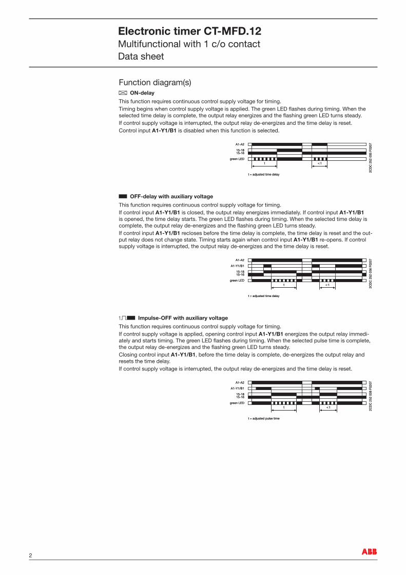
Function diagram(s)A ON-delay
This function requires continuous control supply voltage for timing. Timing begins when control supply voltage is applied. The green LED flashes during timing. When the selected time delay is complete, the output relay energizes and the flashing green LED turns steady. If control supply voltage is interrupted, the output relay de‑energizes and the time delay is reset. Control input A1-Y1/B1 is disabled when this function is selected.
B OFF-delay with auxiliary voltage
This function requires continuous control supply voltage for timing. If control input A1-Y1/B1 is closed, the output relay energizes immediately. If control input A1-Y1/B1 is opened, the time delay starts. The green LED flashes during timing. When the selected time delay is complete, the output relay de‑energizes and the flashing green LED turns steady. If control input A1-Y1/B1 recloses before the time delay is complete, the time delay is reset and the out‑put relay does not change state. Timing starts again when control input A1-Y1/B1 re‑opens. If control supply voltage is interrupted, the output relay de‑energizes and the time delay is reset.
CB Impulse-OFF with auxiliary voltage
This function requires continuous control supply voltage for timing. If control supply voltage is applied, opening control input A1-Y1/B1 energizes the output relay immedi‑ately and starts timing. The green LED flashes during timing. When the selected pulse time is complete, the output relay de‑energizes and the flashing green LED turns steady. Closing control input A1-Y1/B1, before the time delay is complete, de‑energizes the output relay and resets the time delay. If control supply voltage is interrupted, the output relay de‑energizes and the time delay is reset.
A1-A2
15-1615-18
t < t
2CD
C 2
52 0
35 F
0207
green LED
t = adjusted time delay
A1-A2
15-1615-18
t < t
2CD
C 2
52 0
35 F
0207
green LED
t = adjusted time delay
A1-A2
15-1615-18
t
A1-Y1/B1
< t
2CD
C 2
52 0
36 F
0207
green LED
t = adjusted time delay
A1-A2
15-1615-18
t
A1-Y1/B1
< t
2CD
C 2
52 0
36 F
0207
green LED
t = adjusted time delay
A1-A2
15-1615-18
t
A1-Y1/B1
< t
2CD
C 2
52 0
38 F
0207
green LED
t = adjusted pulse time
A1-A2
15-1615-18
t
A1-Y1/B1
< t
2CD
C 2
52 0
38 F
0207
green LED
t = adjusted pulse time
Electronic timer CT-MFD.12Multifunctional with � c/o contactData sheet
3ABB
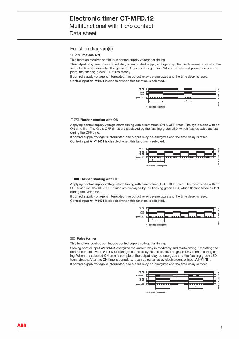
Function diagram(s)CA Impulse-ON
This function requires continuous control supply voltage for timing. The output relay energizes immediately when control supply voltage is applied and de‑energizes after the set pulse time is complete. The green LED flashes during timing. When the selected pulse time is com‑plete, the flashing green LED turns steady. If control supply voltage is interrupted, the output relay de‑energizes and the time delay is reset. Control input A1-Y1/B1 is disabled when this function is selected.
DA Flasher, starting with ON
Applying control supply voltage starts timing with symmetrical ON & OFF times. The cycle starts with an ON time first. The ON & OFF times are displayed by the flashing green LED, which flashes twice as fast during the OFF time. If control supply voltage is interrupted, the output relay de‑energizes and the time delay is reset. Control input A1-Y1/B1 is disabled when this function is selected.
DB Flasher, starting with OFF
Applying control supply voltage starts timing with symmetrical ON & OFF times. The cycle starts with an OFF time first. The ON & OFF times are displayed by the flashing green LED, which flashes twice as fast during the OFF time. If control supply voltage is interrupted, the output relay de‑energizes and the time delay is reset. Control input A1-Y1/B1 is disabled when this function is selected.
H Pulse former
This function requires continuous control supply voltage for timing. Closing control input A1-Y1/B1 energizes the output relay immediately and starts timing. Operating the control contact switch A1-Y1/B1 during the time delay has no effect. The green LED flashes during tim‑ing. When the selected ON time is complete, the output relay de‑energizes and the flashing green LED turns steady. After the ON time is complete, it can be restarted by closing control input A1-Y1/B1. If control supply voltage is interrupted, the output relay de‑energizes and the time delay is reset.
A1-A2
15-1615-18
t < t
2CD
C 2
52 0
37 F
0207
green LED
t = adjusted pulse time
A1-A2
15-1615-18
t < t
2CD
C 2
52 0
37 F
0207
green LED
t = adjusted pulse time
A1-A2
15-1615-18
t t
2CD
C 2
52 0
31 F
0207
green LED
t = adjusted flashing time
A1-A2
15-1615-18
t t
2CD
C 2
52 0
31 F
0207
green LED
t = adjusted flashing time
A1-A2
15-1615-18
t t 2C
DC
252
032
F02
07green LED
t = adjusted flashing time
A1-A2
15-1615-18
t t 2C
DC
252
032
F02
07green LED
t = adjusted flashing time
A1-A2
15-1615-18
t t
A1-Y1/B1
2CD
C 2
52 0
39 F
0207
green LED
t = adjusted pulse time
A1-A2
15-1615-18
t t
A1-Y1/B1
2CD
C 2
52 0
39 F
0207
green LED
t = adjusted pulse time
Electronic timer CT-MFD.12Multifunctional with � c/o contactData sheet
4 ABB
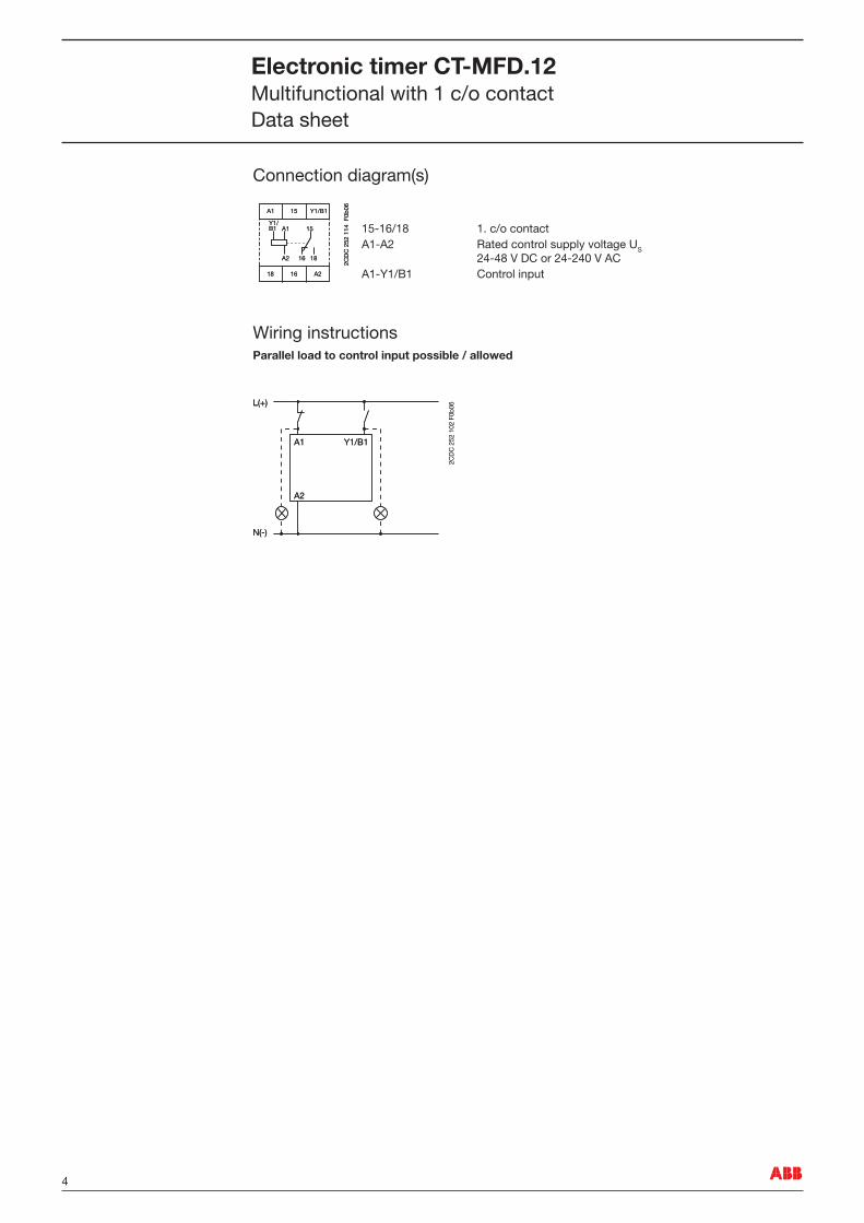
Connection diagram(s)
�5‑�6/�8 �. c/o contactA�‑A2 Rated control supply voltage US
24‑48 V DC or 24‑240 V ACA�‑Y�/B� Control input
Wiring instructionsParallel load to control input possible / allowed
A1
A1
18
18
16
16
A2
A2
15
15
Y1/B1
Y1/B1
2CD
C 2
52 1
14 F
0b06A1
A1
18
18
16
16
A2
A2
15
15
Y1/B1
Y1/B1
2CD
C 2
52 1
14 F
0b06
L(+)
N(-)
A1 Y1/B1
A2
2CD
C 2
52 1
02 F
0b06L(+)
N(-)
A1 Y1/B1
A2
2CD
C 2
52 1
02 F
0b06
Electronic timer CT-MFD.12Multifunctional with � c/o contactData sheet
5ABB
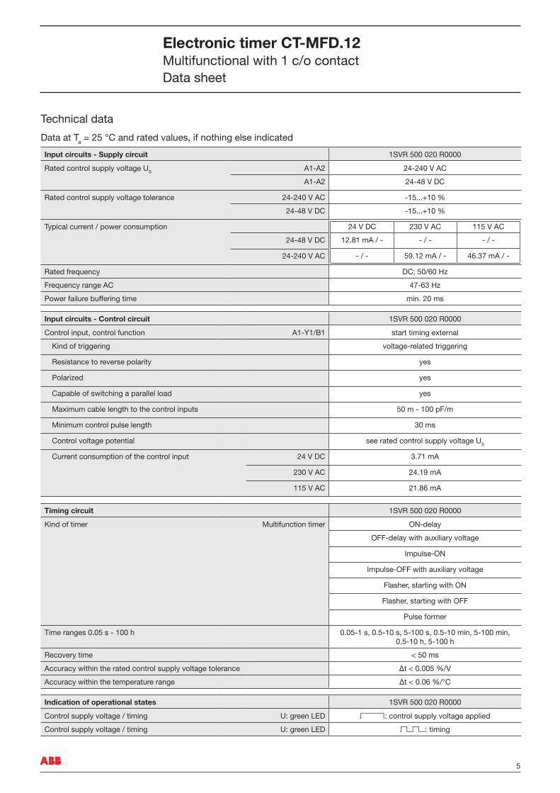
Technical data
Data at Ta = 25 °C and rated values, if nothing else indicated
Input circuits - Supply circuit �SVR 500 020 R0000
Rated control supply voltage US A�‑A2 24‑240 V AC
A�‑A2 24‑48 V DC
Rated control supply voltage tolerance 24‑240 V AC ‑�5...+�0 %
24‑48 V DC ‑�5...+�0 %
Typical current / power consumption 24 V DC 230 V AC ��5 V AC
�2.8� mA / ‑ ‑ / ‑ ‑ / ‑
‑ / ‑ 59.�2 mA / ‑ 46.37 mA / ‑
24‑48 V DC
24‑240 V AC
Rated frequency DC; 50/60 Hz
Frequency range AC 47‑63 Hz
Power failure buffering time min. 20 ms
Input circuits - Control circuit �SVR 500 020 R0000
Control input, control function A�‑Y�/B� start timing external
Kind of triggering voltage‑related triggering
Resistance to reverse polarity yes
Polarized yes
Capable of switching a parallel load yes
Maximum cable length to the control inputs 50 m ‑ �00 pF/m
Minimum control pulse length 30 ms
Control voltage potential see rated control supply voltage US
Current consumption of the control input 24 V DC 3.7� mA
230 V AC 24.�9 mA
��5 V AC 2�.86 mA
Timing circuit �SVR 500 020 R0000
Kind of timer Multifunction timer ON‑delay
OFF‑delay with auxiliary voltage
Impulse‑ON
Impulse‑OFF with auxiliary voltage
Flasher, starting with ON
Flasher, starting with OFF
Pulse former
Time ranges 0.05 s ‑ �00 h 0.05‑� s, 0.5‑�0 s, 5‑�00 s, 0.5‑�0 min, 5‑�00 min, 0.5‑�0 h, 5‑�00 h
Recovery time < 50 ms
Accuracy within the rated control supply voltage tolerance Δt < 0.005 %/V
Accuracy within the temperature range Δt < 0.06 %/°C
Indication of operational states �SVR 500 020 R0000
Control supply voltage / timing U: green LED V: control supply voltage applied
Control supply voltage / timing U: green LED W: timing
Electronic timer CT-MFD.12Multifunctional with � c/o contactData sheet
6 ABB
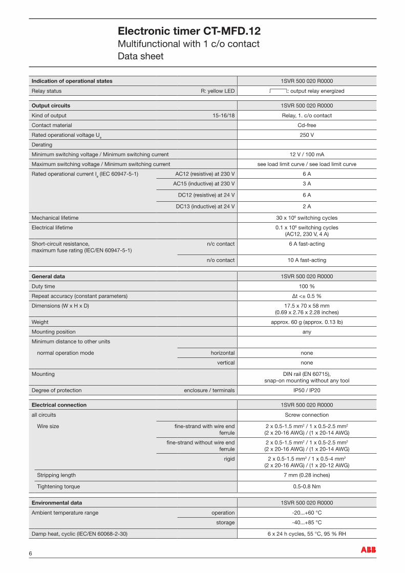
Indication of operational states �SVR 500 020 R0000
Relay status R: yellow LED V: output relay energized
Output circuits �SVR 500 020 R0000
Kind of output �5‑�6/�8 Relay, �. c/o contact
Contact material Cd‑free
Rated operational voltage Ue 250 V
Derating
Minimum switching voltage / Minimum switching current �2 V / �00 mA
Maximum switching voltage / Minimum switching current see load limit curve / see load limit curve
Rated operational current Ie (IEC 60947‑5‑�) AC�2 (resistive) at 230 V 6 A
AC�5 (inductive) at 230 V 3 A
DC�2 (resistive) at 24 V 6 A
DC�3 (inductive) at 24 V 2 A
Mechanical lifetime 30 x �06 switching cycles
Electrical lifetime 0.� x �06 switching cycles (AC�2, 230 V, 4 A)
Short‑circuit resistance, maximum fuse rating (IEC/EN 60947‑5‑�)
n/c contact 6 A fast‑acting
n/o contact �0 A fast‑acting
General data �SVR 500 020 R0000
Duty time �00 %
Repeat accuracy (constant parameters) Δt <± 0.5 %
Dimensions (W x H x D) �7.5 x 70 x 58 mm (0.69 x 2.76 x 2.28 inches)
Weight approx. 60 g (approx. 0.�3 lb)
Mounting position any
Minimum distance to other units
normal operation mode horizontal none
vertical none
Mounting DIN rail (EN 607�5), snap‑on mounting without any tool
Degree of protection enclosure / terminals IP50 / IP20
Electrical connection �SVR 500 020 R0000
all circuits Screw connection
Wire size fine‑strand with wire end ferrule
2 x 0.5‑�.5 mm2 / � x 0.5‑2.5 mm2 (2 x 20‑�6 AWG) / (� x 20‑�4 AWG)
fine‑strand without wire end ferrule
2 x 0.5‑�.5 mm2 / � x 0.5‑2.5 mm2 (2 x 20‑�6 AWG) / (� x 20‑�4 AWG)
rigid 2 x 0.5‑�.5 mm2 / � x 0.5‑4 mm2 (2 x 20‑�6 AWG) / (� x 20‑�2 AWG)
Stripping length 7 mm (0.28 inches)
Tightening torque 0.5‑0.8 Nm
Environmental data �SVR 500 020 R0000
Ambient temperature range operation ‑20...+60 °C
storage ‑40...+85 °C
Damp heat, cyclic (IEC/EN 60068‑2‑30) 6 x 24 h cycles, 55 °C, 95 % RH
Electronic timer CT-MFD.12Multifunctional with � c/o contactData sheet
7ABB
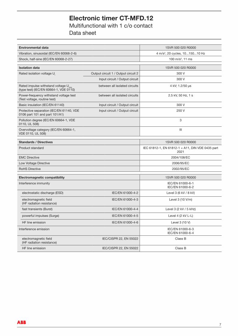
Environmental data �SVR 500 020 R0000
Vibration, sinusoidal (IEC/EN 60068‑2‑6) 4 m/s2, 20 cycles, �0...�50...�0 Hz
Shock, half‑sine (IEC/EN 60068‑2‑27) �00 m/s2, �� ms
Isolation data �SVR 500 020 R0000
Rated isolation voltage Ui Output circuit � / Output circuit 2 300 V
Input circuit / Output circuit 300 V
Rated impulse withstand voltage Uimp (type test) (IEC/EN 60664‑�, VDE 0��0)
between all isolated circuits 4 kV; �.2/50 µs
Power‑frequency withstand voltage test (Test voltage, routine test)
between all isolated circuits 2.5 kV, 50 Hz, � s
Basic insulation (IEC/EN 6��40) Input circuit / Output circuit 300 V
Protective separation (IEC/EN 6��40, VDE 0�06 part �0� and part �0�/A�)
Input circuit / Output circuit 250 V
Pollution degree (IEC/EN 60664‑�, VDE 0��0, UL 508)
3
Overvoltage category (IEC/EN 60664‑�, VDE 0��0, UL 508)
III
Standards / Directives �SVR 500 020 R0000
Product standard IEC 6�8�2‑�, EN 6�8�2‑� + A��, DIN VDE 0435 part 202�
EMC Directive 2004/�08/EC
Low Voltage Directive 2006/95/EC
RoHS Directive 2002/95/EC
Electromagnetic compatibility �SVR 500 020 R0000
Interference immunity IEC/EN 6�000‑6‑� IEC/EN 6�000‑6‑2
electrostatic discharge (ESD) IEC/EN 6�000‑4‑2 Level 3 (6 kV / 8 kV)
electromagnetic field (HF radiation resistance)
IEC/EN 6�000‑4‑3 Level 3 (�0 V/m)
fast transients (Burst) IEC/EN 6�000‑4‑4 Level 3 (2 kV / 5 kHz)
powerful impulses (Surge) IEC/EN 6�000‑4‑5 Level 4 (2 kV L‑L)
HF line emission IEC/EN 6�000‑4‑6 Level 3 (�0 V)
Interference emission IEC/EN 6�000‑6‑3 IEC/EN 6�000‑6‑4
electromagnetic field (HF radiation resistance)
IEC/CISPR 22, EN 55022 Class B
HF line emission IEC/CISPR 22, EN 55022 Class B
Electronic timer CT-MFD.12Multifunctional with � c/o contactData sheet

8 ABB
Technical diagrams
Load limit curve
AC current [A]
resistive load
AC
vol
tage
[V]
2CD
C 2
52 0
44 F
0207
DC current [A]
resistive load
DC
vol
tage
[V]
2CD
C 2
52 0
45 F
0207
AC load (resistive) DC load (resistive)
Derating factor F
cos ϕ
0.5
0.1 0.2 0.3 0.4 0.5 0.6 0.7 0.8 0.9 1.0
0.6
0.7
0.8
0.9
1.0
Der
atin
g fa
ctor
F
2CD
C 2
52 1
24 F
0206
for inductive AC load
Contact lifetime
Switching current [A]
250 Vresistive load
Sw
itchi
ng c
ycle
s
2CD
C 2
52 1
23 F
0206
Electronic timer CT-MFD.12Multifunctional with � c/o contactData sheet
9ABB
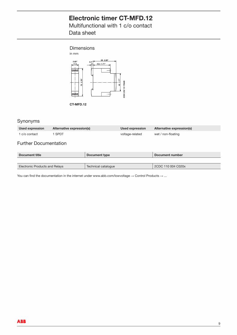
Dimensionsin mm
CT-MFD.12
SynonymsUsed expression Alternative expression(s) Used expression Alternative expression(s)
� c/o contact � SPDT voltage‑related wet / non‑floating
Further Documentation
Document title Document type Document number
Electronic Products and Relays Technical catalogue 2CDC ��0 004 C020x
You can find the documentation in the internet under www.abb.com/lowvoltage R Control Products R ...
0.69“
2.76
“
0.2“2.28“
1.71“
1.77
“
17,5
70
5
58
43,4
45
2CD
C 2
52 1
31 F
0b06
0.69“
2.76
“
0.2“2.28“
1.71“
1.77
“
17,5
70
5
58
43,4
45
2CD
C 2
52 1
31 F
0b06
Electronic timer CT-MFD.12Multifunctional with � c/o contactData sheet

As part of the on‑going product improvement, ABB reserves the right to modify the characteristics of the products described in this document. The information given is non‑contractual. For further details please contact (www.abb.com/contacts) the ABB company marketing these products in your country. D
ocum
ent
num
ber
: 2C
DC
���
058
D02
0� (�
2/20
07)
ABB
ABB STOTZ-KONTAKT GmbH Eppelheimer Strasse 82, 69�23 Heidelberg, Germany Postfach �0 �6 80, 69006 Heidelberg, Germany Internet http://www.abb.com/lowvoltage R Control Products