Embed Size (px)
Citation preview

Data sheet
Sight glass Type MLI
DKRCI.PD.GH0.A7.02 | 520H0764 | 1© Danfoss | DCS (MWA) | 2017.06
Features • MLI are moisture indicators suitable for use with HCFC, HFC and R717 (Ammonia).
• MLI can be used for refrigerants within the temperature range 80 – 40 °C / 176 – 40 °F to maximum operating pressure of 25 bar.
• MLI are available with weld or solder connections.
• MLI 100 can, when the indicator element has been removed, alternatively be used as a normal sight glass for all refrigerants including R717 (ammonia).
The MLI sight glass is mainly used to indicate the condition of the refrigerant as well as the liquid level in the receiver or the oil level in the compressor.
The MLI is equipped with a sensitive indicator that reflects a colour, depending on the moisture content in the refrigerant.
• Classification: DNV, CRN, BV, EAC etc. To get an updated list of certification on the products please contact your local Danfoss Sales Company.
Design • Housing The MLI housing is made of special, cold resistant steel approved for low temperature applications.
• Connections - Welding DIN (2448), DN 20 to 25 - Welding ANSI (B 36.10 Schedule 80), DN 20 to 25
Data sheet | Sight glass, type MLI
© Danfoss | DCS (MWA) | 2017.06 DKRCI.PD.GH0.A7.02 | 520H0764 | 2
Technical data • Max. operating pressure is 25 bar. • The MLI 20-25 are designed for:
Strength test: 50 bar g / 725 psig. Leakage test: 25 bar g / 362 psig.
The moisture liquid indicators are designed as sight glasses with an integral moisture indicator element.
The indicator element is a filter paper impregnated with a chemical salt, which is sensitive to moisture. The indicator element will change color upon detection of moisture within the system. The color change is reversible.
New systems or systems where the drier has been replaced may cause the element to change color almost immediately. However, it is recommended that the plant is allowed to operate for at least 12 hours to allow the system to reach equilibrium before deciding if the drier should be changed.
The drying of the system should be continued until the indicator element stays dark green.
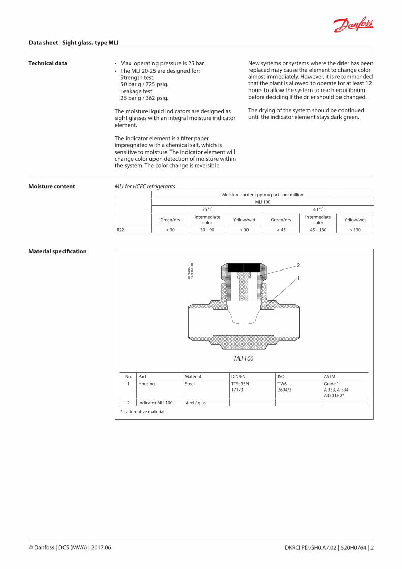
Moisture content Moisture content ppm = parts per million
MLI 100
25 °C 43 °C
Green/dry Intermediate color Yellow/wet Green/dry Intermediate
color Yellow/wet
R22 < 30 30 – 90 > 90 < 45 45 – 130 > 130
MLI for HCFC refrigerants
Material specification
MLI 100
No. Part Material DIN/EN ISO ASTM
1 Housing Steel TTSt 35N17173
TW62604/3
Grade 1A 333, A 334A350 LF2*
2 Indicator MLI 100 steel / glass
* - alternative material

Data sheet | Sight glass, type MLI
© Danfoss | DCS (MWA) | 2017.06 DKRCI.PD.GH0.A7.02 | 520H0764 | 3
Connections
mm inchOD / IDØ mm
OD / IDØ inch
20 ¾” 26.9 / 22.3 1.059 / 0.878
25 1” 33.7 / 28.5 1.327 / 1.122
Welding DIN (2448)
mm inchOD / IDØ mm
OD / IDØ inch
20 ¾” 26.9 / 18.9 1.059 / 0.744
25 1” 33.7 / 24.5 1.327 / 0.965
Welding ANSI (B 36.10 Schedule 80)
Dimensions
Size ConnectionA B C NV Weight
mm in. mm in. mm in. mm in. kg lb
DN 20 D / A85 3.35 57.5 2.26 46 1.81 35 1.38 0.6 1.32
DN 25 D / AD = Welding DIN (2448)A = Welding ANSI (B 36.10 Schedule 80)
Ordering DIN weld connection/ANSI solder connection ANSI connection
Size welding Size solderType Code no. mm inch Type Code no.
mm inch mm inch
20 ¾” 22 7/8” MLI 20 D 100 2511+019 – – – –
25 1” 27 1 1/8” MLI 25 D 100 2511+020 25 1” MLI 25 A 100 2511+089
© Danfoss | DCS (MWA) | 2017.06 DKRCI.PD.GH0.A7.02 | 520H0764 | 4