Embed Size (px)
Citation preview

Inform
ation and visual noncontractual.Subject to engineering changes without notice.
For :Residential, Commercial, Public building, Agricultural and Industrial roofs
Version 1.1 28/11/13
Document validated by NEW TECHNICAL INVESTIGATION n° L13CC0101
The EASY ROOF system is insured provided that the modules have approvals IEC 61215 and IEC 61730
DATA SHEETEASY ROOF
Model “O‐1” EVOLUTIONFor 96 cells PV module 5“ PORTRAIT
See modules compatibility on www.irfts.comNote applicable to the frames whose marking is “0‐1”
1

Inform
ation and visual noncontractual.Subject to engineering changes without notice.
Synopsis
Model “O‐1” 96 Cells 5” Portrait2
1. Nomenclature ................................................................................................................................................. 3
1.1. Parts provided in a kit .............................................................................................................................. 3
1.2. Optional Parts .......................................................................................................................................... 3
1.3. Presentation of the parts of the kit EASY ROOF EVOLUTION .................................................................. 4 1.4. Presentation of the principle of assembly ............................................................................................... 5
2. Glossary ........................................................................................................................................................... 5
3. Under lay film .................................................................................................................................................. 5
4. Illustration of the possible combinations assemblies .... ................................................................................ 6
4.1. Possibility of module’s shift in the rake direction ................................................................................... 7
5. Parts preparation prior to installation ........................................................................................................... 8
6. PV module grounding ..................................................................................................................................... 9
7. Dimension of the photovoltaic field .......................................................................................................... 10‐11
7.1. Dimension of the zone of tiles to be removed .................................................................................... 12‐13
8. Technical standard of the installation and dimensioning of the EASY ROOF EVOLUTION support ........... 14
8.1. Normal zone, common and eave installations ..........................................................................15
8.2. Normal zone, lateral edge or angle installations .......................................................................16
8.3. Sea side zone, common and eave installations ................................................................................ 17
8.4. Sea side zone, lateral edge or angle installations ............................................................................ 18
9. Assembly instruction for EASY ROOF EVOLUTION ....................................................................................... 19
9.1. Field PV centered on rake direction
9.1.1. Removal of the tiles ................................................................................................................... 19
9.1.2. Definition of bottom flashing support batten ........................................................................... 19
9.1.3. Installation of the bottom flashing support batten ................................................................... 20
Installation of the reference support batten ............................................................................. 20
9.1.4. Installation of the bottom flashing ............................................................................................ 21
9.2. PV field positioned at the gutter/eave
9.2.1. Removal of the tiles ................................................................................................................... 22
9.2.2. Positioning of the flooring at the gutter/eave .......................................................................... 22
9.2.3. Specific position of the reference support batten for PV field at the gutter/eave ................... 23
9.2.4. Installation of the bottom metal sheet ................................................................................. 24 à 27
9.3. Flooring installation for all PV field installation ................................................................................ 28
9.3.1. Installation of the battens for assembly with 6 mounting brackets ......................................... 29
9.3.2. Installation of the battens for assembly with 4 mounting brackets ...................................... 30‐31
9.3.3. Installation of leaning batten .................................................................................................... 32
9.4. Installation of the system EASY ROOF EVOLUTION .............................................................................. 33
9.4.1. Installation of the system EASY ROOF EVOLUTION ................................................................... 33
9.4.2. Installation and fixing of the frames and middle brackets .................................................... 34 à 39
9.4.3. Installation and fixing of the left flashings ............................................................................. 40‐41
9.4.4. Installation and fixing of the right flashings ........................................................................... 42‐43
9.4.5. Installation and fixing of the end brackets ............................................................................. 44‐45
9.5. Installation of the photovoltaïcs modules......................................................................................... 46‐47
9.5.1. Grounding ....................................................................................................................................... 48
9.6. Put back the tiles around the PV field .................................................................................................... 49

Inform
ation and visual noncontractual.Subject to engineering changes without notice.
Assembly guide for in roof mounting system Easy‐Roof IRFTS
Model “O‐1” 96 Cells 5” Portrait
(1) Dimensions of these support batten can vary according to the design of the roof structure and the
geographical zone of the building site, see table p. 14 to 17. These support batten will have to be same
thickness as the tiles batten .
(2) Dimensions of this bottom flashing batten can vary according to the roof slope , see table p. 11.
(3) For installation at the gutter.
Number Drsignation item code
1 Frame O‐1 Evolution P001OV40...(*)
2 Left flashing L‐1 Evolution P002LV40...(*)
3 Right flashing L‐1 Evolution P003LV40...(*)
4 Simple fixing clamp Evolution A001V40
5 Double fixing clamp Evolution (1) A002V40
6 Double bracket Evolution A004V40
7 Simple bracket Evolution A003V40
8 Stainless steel rounded end screw 6x40 ‐ A2 V003V02
9 clamp screw M6 x 40 stainless steel ‐ A2 (module from 40 to 50) (2) V013V02
10 EASY ROOF mounting tool L‐1 OUT002V01
11 Double fixing black clamp Evolution (1)
A002V40N
12 Simple fixing blackclamp Evolution A001V40N
13 Simple black bracket Evolution A003V40N
14 Lateral frieze 30/15 F001V40
* : Codification can change according to the choice of the material
Parts provided in the kit
optional parts
Number Designation
a Counter sunk head screw six lobes 5x60 stainless steel ‐A2(wood)
b Counter sunk head screw six lobes 5x30 stainless steel ‐A2(flashings)
c Bottom flashing / Skirt
d Batten 120x27 (3)
e Batten 30x27 (3)
f Batten 40x15 (create a beveled) (4)
g Batten 150x18 (4)
k Batten 180x18 (skirt) (4)
m Bottom metal sheet (5)
Parts not provided in the kit
1)
1.1)
1.2)
3

Inform
ation and visual noncontractual.Subject to engineering changes without notice.
Model “O‐1” 96 Cells 5” Portrait
1
Parts representation
2 3
5
7 8
4
10
11
14
13
12
1.3)
Top flashing included in the frame
4

Inform
ation and visual noncontractual.Subject to engineering changes without notice.
(Exploded View)
Parts marking
Parts marking definition
P001OV40...(*)
frame
P002LV40...(*)
Right flashing
P003LV40...(*)
Left flashing
* : Codification can change according to the choice of the material
Model “O‐1” 96 Cells 5” Portrait
Roofing felt / Roofing underlay
We impose the installation of a roofing felt/roofing underlaybefore the installation of the system of integration EASY‐ROOF.This roofing felt/roofing underlay must comply with regulation
2 lateral flashings by frame height1.4)
2)
3)
5

Inform
ation and visual noncontractual.Subject to engineering changes without notice.
Use of different flashings according to the configuration of the photovoltaic field
Multiple combination for the clearing of roof window or chimney
FRAME
FRAME
FRAME
AD
AD
FRAME
Chimney A
G
AG
AD
AD
Roofwindow
AD
FRAME
FRAME
FRAME FRAME FRAME
FRAME FRAME
FRAME
AG
AG
AG
AG
FRAME
FRAME FRAME FRAME FRAME
FRAME
FRAME FRAME
FRAME FRAME FRAME
AG
FRAME FRAME
AG
AG
AD
AD
FRAME
AD
FRAME
X column
1 line
Model “O‐1” 96 Cells 5” Portrait
(2 flashings)
(2 flashings)
4)
6

Inform
ation and visual noncontractual.Subject to engineering changes without notice.
Possible shift of the panels in the vertical direction
Shift with constant step
Variable shift
X
2/3
1/3
Support battenEnd clamp and bracket
Middle clamp and bracket
Frame
Model “O‐1” 96 Cells 5” Portrait
4.1)
7

Inform
ation and visual noncontractual.Subject to engineering changes without notice.
Parts to be prepared before assembly of the kit
2°) Middle clamp preparation.
Model “O‐1” 96 Cells 5” Portrait
5)
1°) Preparation of the frames
1°) Remove the module centering wedge2°) Remove the frieze support3°) For an installation with 6 fixings per module, cut out and remove the two plugs
1
3
2
Pre mount the module wedge in the slides of each middle clamp (5) or(11).
8
Inform
ation and visual noncontractual.Subject to engineering changes without notice.
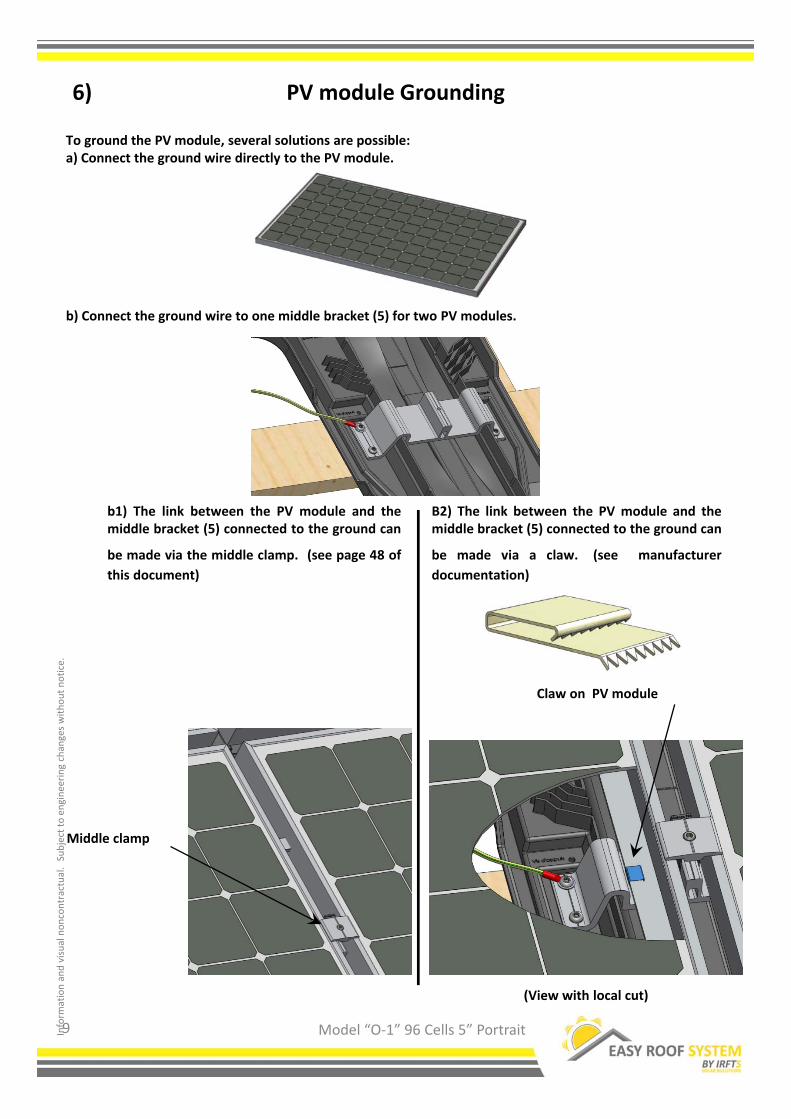
To ground the PV module, several solutions are possible:a) Connect the ground wire directly to the PV module.
b) Connect the ground wire to one middle bracket (5) for two PV modules.
Model “O‐1” 96 Cells 5” Portrait
b1) The link between the PV module and themiddle bracket (5) connected to the ground can
be made via the middle clamp. (see page 48 of
this document)
Middle clamp
B2) The link between the PV module and themiddle bracket (5) connected to the ground can
be made via a claw. (see manufacturer
documentation)
PV module Grounding6)
(View with local cut)
Claw on PV module
9

Inform
ation and visual noncontractual.Subject to engineering changes without notice.
25 mm MINI25 mm MINI 1070 mm X Nbx
Model “O‐1” 96 Cells 5” Portrait
1 2 3 4 5 6 7 8 9 10 11 12 13 14 15 16Dimension X 1110 2180 3250 4320 5390 6460 7530 8600 9670 10740 11810 12880 13950 15020 16090 17160
Module number in length with standard lateral flashings
Ex : (1070 x 12 ) + (2 x 20)= 12880
Dimension of the PV field(Visible Part of the installation)
7)
PV field centered on rake direction X = 1070 x Nbx + (2 x 20)
Lateral eave installation X = 1070 x Nbx + (2 x 25)
Nbx : Number of column of PV module
Field width (mm)
Dimension of the photovoltaic field
Dimension X
1 2 3 4 5 6 7 8 9 10 11 12 13 14 15 16Dimension X 1120 2190 3260 4330 5400 6470 7540 8610 9680 10750 11820 12890 13960 15030 16100 17170
Module number in length for edge installation
Ex : (1070 x 12 ) + (2 x 25)= 12890
a) Common installation (with tiles on both side)
b) Edge installation (no tiles on each side)
1°) Width calculation of the visible field
40 mm MAXI 40 mm MAXI
1070 mm X Nbx
Dimension B > Dimension X
Positioning the photovoltaic field
Dimension B must be positioned with the tiles hollow.
10

Inform
ation and visual noncontractual.Subject to engineering changes without notice.
Dim
ension Y
Dimension A
Model “O‐1” 96 Cells 5” Portrait
Dimension of the PV field(Visible Part of the installation)
7)
a) Determination of dimension A (Bottom flashing batten)The « C » dimension is the Minimum batten width necessaryto avoid reverse slope on the bottom flashing. It’s possibleto use a wider batten, this will simply raise up the PV field.
Dimension of the photovoltaïc field
PV field centered on rake directi
Gutter / eave installation
Step : Step of the system in rake direction, see table below
Nby : Number of l ine of PV module
Field height (mm)
Y = step x (Nby‐1) + 1608 + 114
2°) Height calculation of the visible field
b) Determination of dimension Y
11
Dimension of the visible field = Dimension Y + Dimension A
Roof slope (°)
Minimum batten
width C dimension
(mm)
Mini A
dimension
(mm)
from 10 to 12 250 260
from 13 to 16 220 230
from 17 to 19 180 190
from 20 to 24 150 160
from 25 to 50 120 130Exemple :
1
2
3
4
5
6
7
9572
11142
Nbr of module in
height
Vertical step
Module's lenght (lg)
Dimension Y
1559
1570
1722
3292
4862
6432
8002
Ex : (1570 x (3‐1) ) + 1608+114 = 4862

Inform
ation and visual noncontractual.Subject to engineering changes without notice.
25 mm MINI25 mm MINI 1070 mm X Nbx
Model “O‐1” 96 Cells 5” Portrait
1 2 3 4 5 6 7 8 9 10 11 12 13 14 15 16Dimension L 1460 2530 3600 4670 5740 6810 7880 8950 10020 11090 12160 13230 14300 15370 16440 17510
Module number in length with standard lateral flashings
Ex : (1070 x 12 ) + (2 x 195)= 13230
PV field centered on rake direction L = 1070 x Nbx + (2 x 195)
Lateral eave installation L = 1070 x Nbx + (2 x 25)
Nbx : Number of column of PV module
Field width (mm)
Dimension of the photovoltaïc field
1 2 3 4 5 6 7 8 9 10 11 12 13 14 15 16Dimension L 1120 2190 3260 4330 5400 6470 7540 8610 9680 10750 11820 12890 13960 15030 16100 17170
Module number in length for edge installation
Ex : (1070 x 12 ) + (2 x 25)= 12890
a) Common installation (with tiles on both side)
b) Edge installation (no tiles on each side)
1°) Width calculation of the system to be installed
Dimension of the Easy‐Roof system(With flashings)
7.1)
1070 1070 195195
195 1070
The length of the support batten d* is equal to the dimension L + a sufficient length on each side to lean on the rafter exterior to the frame.
Dimension L
* Reference nomenclature12
Inform
ation and visual noncontractual.Subject to engineering changes without notice.
Model “O‐1” 96 Cells 5” Portrait
1
2
3
4
5
6
7
9666
11236
modules number
in height
System vertical step
Warning : Please check
the PV module
compatibilty list on :
www.irfts.com
Lenth PV module (lg)
Dimension H
1559
1570
1816
3386
4956
6526
8096
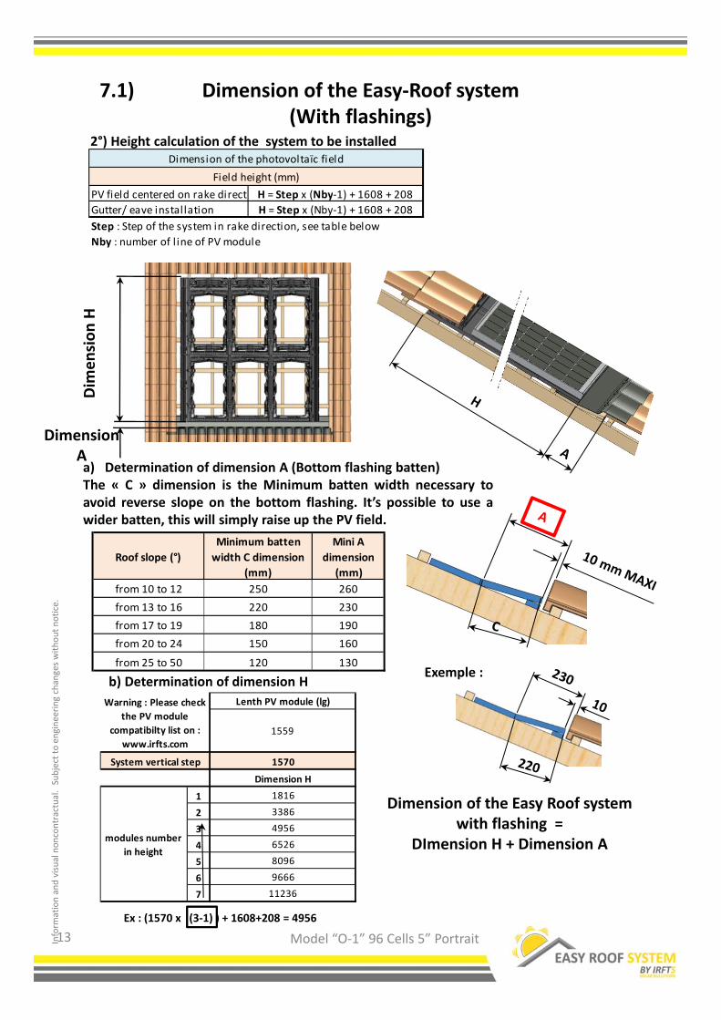
Ex : (1570 x (3‐1) ) + 1608+208 = 4956
Dim
ension H
Dimension Aa) Determination of dimension A (Bottom flashing batten)The « C » dimension is the Minimum batten width necessary toavoid reverse slope on the bottom flashing. It’s possible to use awider batten, this will simply raise up the PV field.
PV field centered on rake directi H = Step x (Nby‐1) + 1608 + 208
Gutter/ eave installation H = Step x (Nby‐1) + 1608 + 208
Step : Step of the system in rake direction, see table below
Nby : number of l ine of PV module
Field height (mm)
Dimension of the photovoltaïc field
2°) Height calculation of the system to be installed
b) Determination of dimension H
Dimension of the Easy‐Roof system(With flashings)
7.1)
13
Dimension of the Easy Roof system with flashing =
DImension H + Dimension A
Roof slope (°)
Minimum batten
width C dimension
(mm)
Mini A
dimension
(mm)
from 10 to 12 250 260
from 13 to 16 220 230
from 17 to 19 180 190
from 20 to 24 150 160
from 25 to 50 120 130Exemple :

Inform
ation and visual noncontractual.Subject to engineering changes without notice.
Model “O‐1” 96 Cells 5” Portrait
The selection and the dimensioning of the support batten of the EASY‐ROOF system are done according to the type of roof structure. The Easy Roof system can be installed on roofs with a slope from 10° to 50° only.
Use the tables of the following pages to determine the dimension of the support battens .
The number of fixing points per panel can be 4 or 6 according to the support battenchoosen.
The values on the following tables apply only for the geographical zones from 1 to 4 of the regulation snow and wind according to standard NF EN 1991‐1 ‐ 4 and for an
altitude lower than 900m. For zone 5 a technical study and of feasibility will have to be
made on a case‐by‐case basis.
It is imperative to respect these instructions of dimensioning.
The maximum admissible loads are :Upward :
With 4 brackets per module : 3700 Pa With 6 brackets par module : 5540 Pa
downward :With 4 brackets per module : 3900 Pa
With 6 brackets par module : 5850 Pa
Technical standard8)
14
Note that the conditions of guarantee can be applied only if the implementation hasbeen done in accordance with the rules prescribed in the present note and withdifferent the appendices to which it could refer.

Inform
ation and visual noncontractual.Subject to engineering changes without notice.
Model “O‐1” 96 Cells 5” Portrait15
Centre distance <= 600 15 250 2 15 300 2 15 300 2 15 300 2 5x60/32
Truss 22 150 2 22 150 2 22 150 2 22 150 2 5x60/32
or rafters 27 120 2 27 120 2 27 120 2 27 120 2 5x60/33
centre distance 40 100 2 40 100 2 40 100 2 40 100 2 5x70/32
600 < centre distance < = 900 22 150 3 22 150 3 22 150 3 22 150 3 5x60/32
Truss or rafters 27 120 3 27 120 3 27 120 3 27 120 3 5x60/32
centre distance 40 100 3 40 100 3 40 100 3 40 100 3 5x70/32
Centre distance < = 1500
440 130 3
440 130 3
440 130 3
440 130 3 5x70/32
metal truss 6 40 100 3 6 40 100 3 6 40 100 3 6 40 100 3 5x70/32
centre distance < = 1500 (2) 22 200 4 22 200 4 22 200 4 22 200 4 5x60/32
w ood structure 27 180 4 27 180 4 27 180 4 27 180 4 5x60/32
on rake direction 40 100 4 40 100 4 40 100 4 40 100 4 5x70/32
Centre distance < = 1500 (2)
440 130 4/3(1)
440 130 4/3(1)
440 130 4/3(1)
440 130 4/3(1) 5x70/32
Wood or metal frame 6 40 100 4/3(1) 6 40 100 4/3(1) 6 40 100 4/3(1) 6 40 100 4/3(1) 5x70/32
Centre distance <= 600 15 250 2 15 250 2 15 250 2 15 250 2 5x60/32
Truss 22 150 2 22 150 2 22 150 2 22 150 2 5x60/32
or rafters 27 120 2 27 120 2 27 120 2 27 120 2 5x60/33
centre distance 40 100 2 40 100 2 40 100 2 40 100 2 5x70/32
600 < centre distance < = 900 22 150 3 22 150 3 22 150 3 22 150 3 5x60/32
Truss or rafters 27 120 3 27 120 3 27 120 3 27 120 3 5x60/32
centre distance 40 100 3 40 100 3 40 100 3 40 100 3 5x70/32
Centre distance < = 1500
440 130 3
440 130 3
440 130 3
440 130 3 5x70/32
metal truss 6 40 100 3 6 40 100 3 6 40 100 3 6 40 100 3 5x70/32
centre distance < = 1500 (2) 22 200 4 22 200 4 22 200 4 22 200 4 5x60/32
w ood structure 27 180 4 27 180 4 27 180 4 27 180 4 5x60/32
on rake direction 40 100 4 40 100 4 40 100 4 40 100 4 5x70/32
Centre distance < = 1500 (2)
440 130 4/3(1)
440 130 4/3(1)
440 130 4/3(1)
440 130 4/3(1) 5x70/32
Wood or metal frame 6 40 100 4/3(1) 6 40 100 4/3(1) 6 40 100 4/3(1) 6 40 100 4/3(1) 5x70/32
Normal
4 4 4
Gu
tte
r /e
av
e
4
4 4 4
Co
mm
on
ins
talla
tio
n
4 4 4
4
4
4
4 4 4
4
4 4 4
4
4 4
From 10° to 50°, normal zone (category IIIa ) 2 slopes roof
Zone 1 Zone 2 Zone 3 Zone 4
4
8.1) Normal zone, common and eave installations
Technical standard

Inform
ation and visual noncontractual.Subject to engineering changes without notice.
Model “O‐1” 96 Cells 5” Portrait16
Centre distance <= 600 15 250 2 15 250 2 15 250 2 15 250 2 5x60/32
Truss 22 150 2 22 150 2 22 150 2 22 150 2 5x60/32
or rafters 27 120 2 27 120 2 27 120 2 27 120 2 5x60/33
centre distance 40 100 2 40 100 2 40 100 2 40 100 2 5x70/32
600 < centre
distance < = 900 22 150 3 22 150 3 22 150 3 22 150 3 5x60/32
Truss or rafters 27 120 3 27 120 3 27 120 3 27 120 3 5x60/32
centre distance 40 100 3 40 100 3 40 100 3 40 100 3 5x70/32
Centre distance < =
15004
40 130 34
40 130 34
40 130 34
40 130 3 5x70/32
metal truss 6 40 100 3 6 40 100 3 6 40 100 3 6 40 100 3 5x70/32
centre distance < =
1500 (2) 22 200 4 22 200 4 22 200 4 22 200 4 5x60/32
w ood structure 27 180 4 27 180 4 27 180 4 27 180 4 5x60/32
on rake direction 40 100 4 40 100 4 40 100 4 40 100 4 5x70/32
Centre distance < =
1500 (2)4
40 130 4/3(1)4
40 130 4/3(1)4
40 130 4/3(1)4
40 130 4/3(1) 5x70/32
Wood or metal f rame 6 40 100 4/3(1) 6 40 100 4/3(1) 6 40 100 4/3(1) 6 40 100 4/3(1) 5x70/32
Centre distance <= 600 15 250 2 15 250 2 15 250 2 15 250 2 5x60/32
truss or rafters 22 150 2 22 150 2 22 150 2 22 150 2 5x60/32
centre distance 27 120 2 27 120 2 27 120 2 27 120 2 5x60/33
40 100 2 40 100 2 40 100 2 40 100 2 5x70/32
600 < Centre
distance < = 900 22 150 3 22 150 3 22 150 3 22 150 3 5x60/32
truss or rafters 27 120 3 27 120 3 27 120 3 27 120 3 5x60/32
centre distance 40 100 3 40 100 3 40 100 3 40 100 3 5x70/32
C entre dis tance < =
15004 40 130 3 4 40 130 3 4 40 130 3 4 40 130 3 5x70/32
Metal truss 6 40 100 3 6 40 100 3 6 40 100 3 6 40 100 3 5x70/32
C entre dis tance (2 ) 22 200 4 22 200 4 22 200 4 22 200 4 5x60/32
w ood structure 27 180 4 27 180 4 27 180 4 27 180 4 5x60/32
on rake direction 40 100 4 40 100 4 40 100 4 40 100 4 5x70/32
C entre dis tance < =
1500 (2 )4 40 130 4/3(1) 4 40 130 4/3(1) 4 40 130 4/3(1) 4 40 130 4/3(1) 5x70/32
w ood or metal structure 6 40 100 4/3(1) 6 40 100 4/3(1) 6 40 100 4/3(1) 6 40 100 4/3(1) 5x70/32
(1) : 4 for w ood frame / 3 for metal f rame.
(2) : w ood installation on rake direction.
From 10° to 50°, normal zone (category IIIa ) 2 slopes roof
Zone 1 Zone 2 Zone 3 Zone 4
Normal
4
4
An
gle
4 4 4 4
Sid
e e
dg
e
4 4 4
4 4 4
4 4 4 4
8.2) Normal zone, side edge or angle installations
Technical standard

Inform
ation and visual noncontractual.Subject to engineering changes without notice.
Model “O‐1” 96 Cells 5” Portrait17
Centre distance <= 600 15 250 2 15 300 2 15 300 2 15 300 2 5x60/32
Truss 22 150 2 22 150 2 22 150 2 22 150 2 5x60/32
or rafters 27 120 2 27 120 2 27 120 2 27 120 2 5x60/33
centre distance 40 100 2 40 100 2 40 100 2 40 100 2 5x70/32
600 < centre
distance < = 900 22 150 3 22 150 3 22 150 3 22 150 3 5x60/32
Truss or rafters 27 120 3 27 120 3 27 120 3 27 120 3 5x60/32
centre distance 40 100 3 40 100 3 40 100 3 40 100 3 5x70/32
Centre distance < =
15004
40 130 34
40 130 34
40 130 34
40 130 3 5x70/32
metal truss 6 40 100 3 6 40 100 3 6 40 100 3 6 40 100 3 5x70/32
centre distance < =
1500 (2) 22 200 4 22 200 4 22 200 4 22 200 4 5x60/32
w ood structure 27 180 4 27 180 4 27 180 4 27 180 4 5x60/32
on rake direction 40 100 4 40 100 4 40 100 4 40 100 4 5x70/32
Centre distance < =
1500 (2)4
40 130 4/3(1)4
40 130 4/3(1)4
40 130 4/3(1)4
40 130 4/3(1) 5x70/32
Wood or metal f rame 6 40 100 4/3(1) 6 40 100 4/3(1) 6 40 100 4/3(1) 6 40 100 4/3(1) 5x70/32
Centre distance <= 600 15 250 2 15 250 2 15 250 2 15 250 2 5x60/32
Truss 22 150 2 22 150 2 22 150 2 22 150 2 5x60/32
or rafters 27 120 2 27 120 2 27 120 2 27 120 2 5x60/33
centre distance 40 100 2 40 100 2 40 100 2 40 100 2 5x70/32
600 < centre
distance < = 900 22 150 3 22 150 3 22 150 3 22 150 3 5x60/32
Truss or rafters 27 120 3 27 120 3 27 120 3 27 120 3 5x60/32
centre distance 40 100 3 40 100 3 40 100 3 40 100 3 5x70/32
Centre distance < =
15004
40 130 34
40 130 34
40 130 34
40 130 3 5x70/32
metal truss 6 40 100 3 6 40 100 3 6 40 100 3 6 40 100 3 5x70/32
centre distance < =
1500 (2) 22 200 4 22 200 4 22 200 4 22 200 4 5x60/32
w ood structure 27 180 4 27 180 4 27 180 4 27 180 4 5x60/32
on rake direction 40 100 4 40 100 4 40 100 4 40 100 4 5x70/32
Centre distance < =
1500 (2)4
40 130 4/3(1)4
40 130 4/3(1)4
40 130 4/3(1)4
40 130 4/3(1) 5x70/32
Wood or metal f rame 6 40 100 4/3(1) 6 40 100 4/3(1) 6 40 100 4/3(1) 6 40 100 4/3(1) 5x70/32
(1) : 4 for w ood frame / 3 for metal f rame.
(2) : w ood installation on rake direction.
Gu
tte
r / E
av
e
6 6 6 6
6 6 6 6
6 6 6 6
Co
mm
on
ins
talla
tio
n
6 6 6 6
6 6 6 6
6 6 6 6
From 10° to 50° - exposed site (category I ) 2 slopes roof
Zone 1 Zone 2 Zone 3 Zone 4
seaside
8.3) Sea side zone, common and eave installations
Technical standard

Inform
ation and visual noncontractual.Subject to engineering changes without notice.
Model “O‐1” 96 Cells 5” Portrait18
Centre distance <= 600 15 250 2 15 250 2 15 250 2 15 250 2 5x60/32
Truss 22 150 2 22 150 2 22 150 2 22 150 2 5x60/32
or rafters 27 120 2 27 120 2 27 120 2 27 120 2 5x60/33
centre distance 40 100 2 40 100 2 40 100 2 40 100 2 5x70/32
600 < centre
distance < = 900 22 150 3 22 150 3 22 150 3 22 150 3 5x60/32
Truss or rafters 27 120 3 27 120 3 27 120 3 27 120 3 5x60/32
centre distance 40 100 3 40 100 3 40 100 3 40 100 3 5x70/32
Centre distance < =
15004
40 130 34
40 130 34
40 130 34
40 130 3 5x70/32
metal truss 6 40 100 3 6 40 100 3 6 40 100 3 6 40 100 3 5x70/32
centre distance < =
1500 (2) 22 200 4 22 200 4 22 200 4 22 200 4 5x60/32
w ood structure 27 180 4 27 180 4 27 180 4 27 180 4 5x60/32
on rake direction 40 100 4 40 100 4 40 100 4 40 100 4 5x70/32
Centre distance < =
1500 (2)4
40 130 4/3(1)4
40 130 4/3(1)4
40 130 4/3(1)4
40 130 4/3(1) 5x70/32
Wood or metal f rame 6 40 100 4/3(1) 6 40 100 4/3(1) 6 40 100 4/3(1) 6 40 100 4/3(1) 5x70/32
(1) : 4 for w ood frame / 3 for metal f rame.
(2) : w ood installation on rake direction.
An
gle
6 6 6 6
6 6 6 6
6 6 4 6
Sid
e e
dg
e
6 6 6 6
6 6 6
6 4 4 6
From 10° to 50° - exposed site (category I ) 2 slopes roof
Zone 1 Zone 2 Zone 3 Zone 4
seaside
8.4) Sea side zone, side edge or angle installations
Technical standard
Inform
ation and visual noncontractual.Subject to engineering changes without notice.
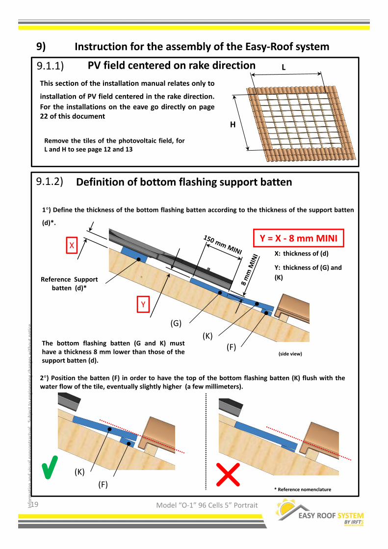
9.1.1)
Remove the tiles of the photovoltaic field, forL and H to see page 12 and 13
* Reference nomenclature
9.1.2)
Model “O‐1” 96 Cells 5” Portrait
H
LPV field centered on rake direction
This section of the installation manual relates only to
installation of PV field centered in the rake direction.
For the installations on the eave go directly on page22 of this document
Definition of bottom flashing support batten
(side view)
Y = X ‐ 8 mm MINI
1°) Define the thickness of the bottom flashing batten according to the thickness of the support batten
(d)*.
Reference Support batten (d)*
(G)
(F)(K)
X
Y
X: thickness of (d)
Y: thickness of (G) and
(K)
(F)
2°) Position the batten (F) in order to have the top of the bottom flashing batten (K) flush with thewater flow of the tile, eventually slightly higher (a few millimeters).
(K)
19
The bottom flashing batten (G and K) musthave a thickness 8 mm lower than those of thesupport batten (d).
Instruction for the assembly of the Easy‐Roof system9)

Inform
ation and visual noncontractual.Subject to engineering changes without notice.
9.1.3)
2°) Set up the bottom flashing batten at 10 mm MAXIMUM to the top of the tile . Use the wood (G)and (K) defined in the preceding operation. Place a tile batten (e) against the batten (G).Screw with stainless screws 5x60 milled head.
* Reference nomenclature
Model “O‐1” 96 Cells 5” Portrait
3°) Set up the first reference support batten d*. Position this support batten 380 mm to the break of
the bottom flashing flooring. (equal to 380mm + A from the top of the tile)Screw the support batten following the recommendations page 15 to 18 to know the type and thenumber of screws to be used.
Installation of the bottom flashing support batten and the reference support batten.
The bottom flashing batten and thebottom flashing itself will have to be2 tiles longer on each side of the PVfield.
0°
1°) Determination of dimension A (Bottom flashing batten)The « C » dimension is the Minimum batten width necessary to avoid reverse slope on the bottomflashing. It’s possible to use a wider batten, this will simply raise up the PV field.
(G)
(K)
(F)Reference support batten(d)*
20
PV field centered on rake direction
Reverse slope FORBIDDEN
Roof slope (°)
Minimum batten
width C dimension
(mm)
Mini A
dimension
(mm)
from 10 to 12 250 260
from 13 to 16 220 230
from 17 to 19 180 190
from 20 to 24 150 160
from 25 to 50 120 130
(g)(k)
(f)Planche support de référence(d)*
(e)

Inform
ation and visual noncontractual.Subject to engineering changes without notice.
Model “O‐1” 96 Cells 5” Portrait
9.1.4) Installation of the bottom flashingSet up the bottom flashing. Attention not to stick the ends and the higher edge, in order to be
able to flip over the ends.The overlap on the tiles will be made according to the tiles model.
Make sure that the tiles are covered with 150 mm MINI.
* Reference nomenclature
Make a flip over from 10 to 15 mm on the higher edge of the bottom flashing over all the width of the PV field
Make a flip over from 10 to 15 mm on the right and left side of the bottom flashing on
all the height
(Left side of PV field )(Right side of PV field )
Bottom flashing MINI “width” = (2 X 150) + dimension A
reference support batten (d)
150 mm MINI
Bottom flashing“width”
21
PV field centered on rake direction
Carde Easy‐roof

Inform
ation and visual noncontractual.Subject to engineering changes without notice.
9.2.1)
Set up the first support batten at 435 mm from the first battenor the eave batten (tilting lath).Screw the support batten following the recommendations page15 to 18 to know the type and the number of screws to be used..
* Reference nomenclature
9.2.2)
Model “O‐1” 96 Cells 5” Portrait
Reference support batten (d)*
PV field positioned at the gutter/eave
Positioning of the flooring at the gutter/eave
This section of the assembly guide relates only to the installations of PV fieldpositioned at the gutter/eave
CAUTION: The low part of PV field (with the gutter) must
imperatively be on the same plan as the flooring of the system.
In the contrary case the dimension of 435 mm is not applicable
any more. It is necessary to go move up the PV field in the rake
direction. The dimension of positioning must be redefined, see
page 23.
0°
Reverse slope FORBIDDEN
Remove the tiles of the photovoltaic field, for L and H to see page 12 and 13
H
L
22
PV field positioned at the gutter/eave

Inform
ation and visual noncontractual.Subject to engineering changes without notice.
0°
0°
5°
Model “O‐1” 96 Cells 5” Portrait
Specific position of the reference support battenfor PV field at the gutter/eave
“M” to be measured on the roof by observing the conditions described here
X (mm) = 380 (mm) + M
Reference support batten(d)*
* Reference nomenclature
9.2.3)
23
Reverse slope FORBIDDEN
PV field positioned at the gutter/eave

Inform
ation and visual noncontractual.Subject to engineering changes without notice.
Model “O‐1” 96 Cells 5” Portrait
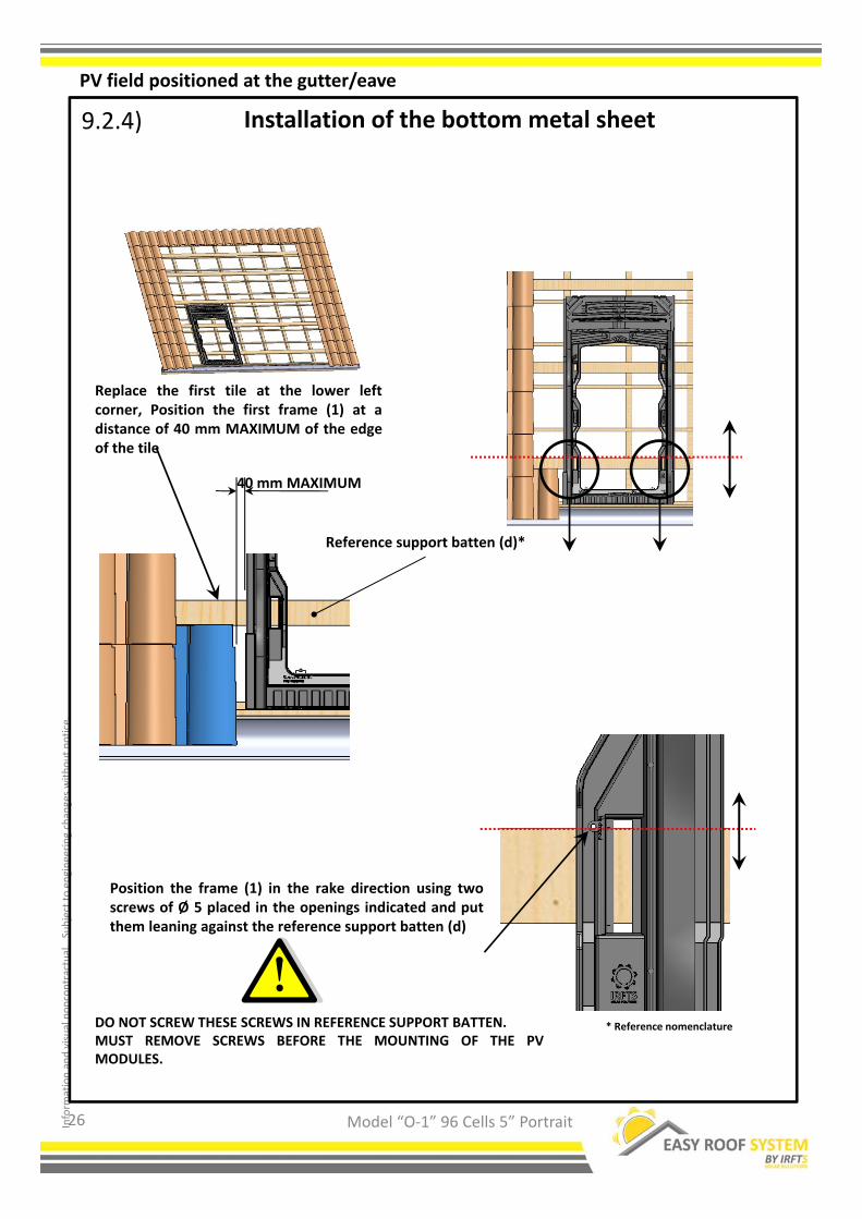
Installation of the bottom metal sheet9.2.4)
To realize the bottom metal sheet, the A1 angle is equal to 90°+ the angle of inclination of the roof.
Example: A1 = 90° +30° = 120°
the L1 dimension is defined by the position of the gutter. Define L1 so that the low end of the metal sheet
is at least 20 mm in the gutter.
NOTE: this kind of metal sheet is applicable only for the PV field positioned at the gutter/eave. See
paragraph 9.2.4 page 25.
(cross section)(cross section)
The length of the metal sheet can be variable. If it is needed to use several metal sheets, those will
have imperatively to overlap of 100 mm MINI.
Metal sheet in transparency
Align the fold of the metal sheet with the edge of the batten
24
PV field positioned at the gutter/eave

Inform
ation and visual noncontractual.Subject to engineering changes without notice.
Model “O‐1” 96 Cells 5” Portrait
Installation of the bottom metal sheet9.2.4)
Add a batten or a support batten under the bottom metal sheet to support this one. This batten
will at least make all the width of the PV field. The thickness of this batten will be identical to the
thickness of the support batten (d)*.
Align the batten with the higher edge of thebottom metal sheet
Bottom metal sheet in transparency
(View of top)
Set up and fasten the bottom metal sheet all over the width of the PV field. Fasten only the top part ofthe bottom metal sheet.
* Reference nomenclature
25
PV field positioned at the gutter/eave
Inform
ation and visual noncontractual.Subject to engineering changes without notice.
9.2.4)
Model “O‐1” 96 Cells 5” Portrait
Position the frame (1) in the rake direction using twoscrews of Ø 5 placed in the openings indicated and putthem leaning against the reference support batten (d)
* Reference nomenclature
Replace the first tile at the lower leftcorner, Position the first frame (1) at adistance of 40 mm MAXIMUM of the edgeof the tile
40 mm MAXIMUM
Reference support batten (d)*
26
Installation of the bottom metal sheet
PV field positioned at the gutter/eave
DO NOT SCREW THESE SCREWS IN REFERENCE SUPPORT BATTEN.MUST REMOVE SCREWS BEFORE THE MOUNTING OF THE PVMODULES.

Inform
ation and visual noncontractual.Subject to engineering changes without notice.
Model “O‐1” 96 Cells 5” Portrait
Installation of the bottom metal sheet9.2.4)
The bottom metal sheet must be aligned with the frames on each side of the PV field.
Position all the frames of the first line while proceeding as indicated page 26. Do a marking at each
end on the wood. Then slide the frames upward slightly.
(view with fictitious frames)Marking
(view with fictitious frames) (view with fictitious frames)
Marking
Cut the top batten of the double lath 250mm wider than the marking so that the remaining batten ison the same level as the reference support batten.
250 mm 250 mm
27
PV field positioned at the gutter/eave

Inform
ation and visual noncontractual.Subject to engineering changes without notice.
Model “O‐1” 96 Cells 5” Portrait
The length “L” of the support battens (d)* must imperatively make all the width of the PV field.For the value “L” to see table page 12 of this document.If needed, add to this dimension “L” a sufficient length on each side of PV field so that the ends of thebatten lean on the rafter on both sides.
28
* Reference nomenclature
(view with fictitiousframes)
(Left side of PV field) (Right side of PV field)
L
Flooring Installation
Flooring installation for all PV field installation 9.3)
Inform
ation and visual noncontractual.Subject to engineering changes without notice.
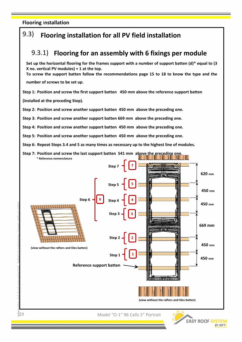
Flooring installation for all PV field installation
Set up the horizontal flooring for the frames support with a number of support batten (d)* equal to (3X no. vertical PV modules) + 1 at the top.To screw the support batten follow the recommendations page 15 to 18 to know the type and the
number of screws to be set up.
Model “O‐1” 96 Cells 5” Portrait
9.3)
* Reference nomenclature
(view without the rafters and tiles batten)
(view without the rafters and tiles batten)
Step 1: Position and screw the first support batten 450 mm above the reference support batten
(installed at the preceding Step).
Step 2: Position and screw another support batten 450 mm above the preceding one.
Step 3: Position and screw another support batten 669 mm above the preceding one.
Step 4: Position and screw another support batten 450 mm above the preceding one.
Step 5: Position and screw another support batten 450 mm above the preceding one.
Step 6: Repeat Steps 3.4 and 5 as many times as necessary up to the highest line of modules.
Step 7: Position and screw the last support batten 541 mm above the preceding one.
Reference support batten
1
2
5
7
Step 1
Step 2
Step 5
Step 7
6Step 6
3Step 3
669 mm
450 mm
620 mm
450 mm
450 mm
450 mm
4Step 4
29
Flooring for an assembly with 6 fixings per module9.3.1)
Flooring installation

Inform
ation and visual noncontractual.Subject to engineering changes without notice.
Model “O‐1” 96 Cells 5” Portrait
Reference support batten
1
2
3
5
Step 1
Step 2
Step 3
Step 5
669 mm
900 mm
900 mm
620 mm
4Step 4
Step 1: Position and screw the first support batten 900 mm above the reference support batten
(installed at the preceding Step).
Step 2: To position and screw another support batten 669 mm above the preceding one.
Step 3: Position and screw another support batten 900 mm above the preceding one.
Step 4: Repeat Steps 2 and 3 as many times as necessary up to the highest line of modules.
Step 5: Position and screw the last support batten 541 mm above the preceding one.
Set up the horizontal flooring for the frames support with a number of support batten (d)* equal to(2 X no. vertical PV modules) + 1 at the top.To screw the support batten follow the recommendations page 15 to 18 to know the type and thenumber of screws to be set up.
* Reference nomenclature
(view without the rafters and tiles batten)
(view without the rafters and tiles batten)
30
Flooring installation for all PV field installation 9.3)
Flooring for an assembly with 4 fixings per module9.3.2)
Flooring installation

Inform
ation and visual noncontractual.Subject to engineering changes without notice.
On an assembly with 4 fixings per module, it is necessary to add and fix battens on each side of the PV
field, with a thickness and width identical to the support batten (d)*. These battens will be used for the
fixing of side flashings.The battens must pass under the frame, to exceed this one of at least 200 mm MINI outside the PV field.For a roof without tiles battens, it is imperatively necessary to add a horizontal batten with a thicknessidentical to the support batten (d)* by line of frame, centered on the height of each line, over all the widthof the PV field.
Model “O‐1” 96 Cells 5” Portrait
9.3.2)
* Reference nomenclature
Flooring for an assembly with 4 fixings per module
(Left side of PV field) (Right side of PV field)
Battensto add
Battens
to add
Support Battensto add
Support Battensto add
200 mm MINI
Reference support batten
(view without the tiles batten)
1°) Position and screw a support batten at450 mm ±100 from the preceding one in
each interval of 900 mm
2°) If necessary according to the recommendations, position and screw the battens all over the width of the PV field leaning against the battenspreviously posed.
450 ±100 mm
450 ±100mm
900 mm
31
Flooring installation

Inform
ation and visual noncontractual.Subject to engineering changes without notice.
Installation of leaning battenTo ensure a good support where the frames overlap it is necessary to set up and to fix a horizontal battenevery three support battens (d)* for the assemblies with 6 fixings, every 2 support battens (d)* for theassembly with 4 fixings.
If no tiles battens exists in the zones described below, add battens all over the width of the PV field.
Those battens will have the same thickness as the support batten(d)*. Position at 290 ± 50 mm of the
lower support batten.
It is imperative to make this operation for all the lines of frame of the PV field.
Model “O‐1” 96 Cells 5” Portrait
9.3.3)
* Reference nomenclature
290 ± 50mm
(Dimension Detail)
Reference support batten (view without the rafters and ltiles batten)
(view without the tiles batten)
(Left side of PV field) (Right side of PV field)
Liteaux withto add
Liteaux
with
to add
Flooring with 6 fixings per PV module
(view without the rafters and tiles batten)
290 ± 50mm
290 ± 50mm2 support battens
2 support battens
Flooring with 4 fixings per PV module
3 support battens
3 support battens
290 ± 50mm
290 ± 50mm
32
Flooring installation

Inform
ation and visual noncontractual.Subject to engineering changes without notice.
Model “O‐1” 96 Cells 5” Portrait
9.4)
This section of the installation manual relates to all kind of installation (middleof the rake or at the gutter)
Installation of system EASY‐ROOF
33

Inform
ation and visual noncontractual.Subject to engineering changes without notice.
Model “O‐1” 96 Cells 5” Portrait
9.4.2) Installation of the EASY‐ROOF system
Position the frame (1) in the rake direction using twoscrews of Ø 5 placed in the openings indicated and putthem leaning against the reference support batten (d).
Replace the first tile with the left lowercorner, Position the first frame (1) at adistance of 40 mm MAXIMUM of the edgeof the tile.
* Reference nomenclature
40 mm MAXIMUM
Reference support batten (d)*
34
DO NOT SCREW THESE SCREWS IN REFERENCE SUPPORT BATTEN.MUST REMOVE SCREWS BEFORE THE MOUNTING OF THE PVMODULES.

Inform
ation and visual noncontractual.Subject to engineering changes without notice.
Model “O‐1” 96 Cells 5” Portrait
Installation of the EASY‐ROOF system1°) Set up and interlock another frame
above the precedent. Align them
perfectly in the vertical direction. (do a
marking with the chalk line)
2°) Set up another frame on the first line. Align this one on the
reference support batten as indicated page 34.
Reference support batten (d)*
* Reference nomenclature
35
9.4.2)
Inform
ation and visual noncontractual.Subject to engineering changes without notice.
Model “O‐1” 96 Cells 5” Portrait
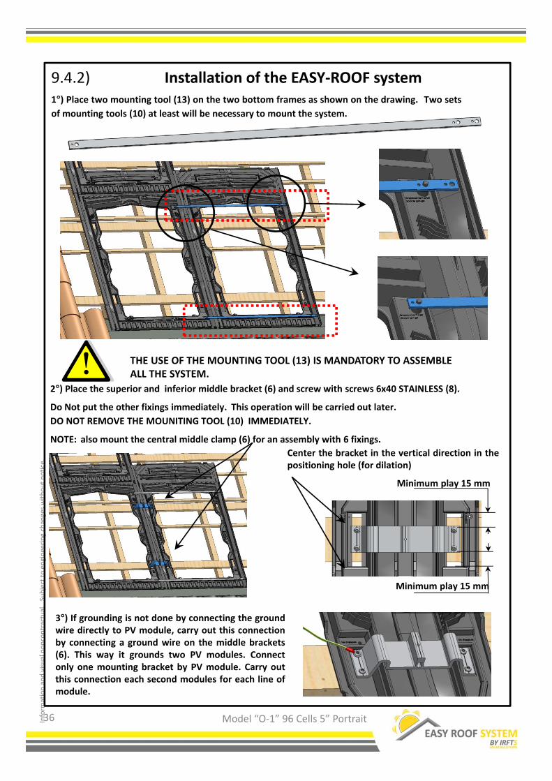
Installation of the EASY‐ROOF system1°) Place two mounting tool (13) on the two bottom frames as shown on the drawing. Two sets
of mounting tools (10) at least will be necessary to mount the system.
2°) Place the superior and inferior middle bracket (6) and screw with screws 6x40 STAINLESS (8).
Do Not put the other fixings immediately. This operation will be carried out later.
DO NOT REMOVE THE MOUNITING TOOL (10) IMMEDIATELY.
NOTE: also mount the central middle clamp (6) for an assembly with 6 fixings.
3°) If grounding is not done by connecting the groundwire directly to PV module, carry out this connectionby connecting a ground wire on the middle brackets(6). This way it grounds two PV modules. Connectonly one mounting bracket by PV module. Carry outthis connection each second modules for each line ofmodule.
THE USE OF THE MOUNTING TOOL (13) IS MANDATORY TO ASSEMBLE ALL THE SYSTEM.
Center the bracket in the vertical direction in thepositioning hole (for dilation)
36
9.4.2)
Minimum play 15 mm
Minimum play 15 mm
Inform
ation and visual noncontractual.Subject to engineering changes without notice.
Model “O‐1” 96 Cells 5” Portrait
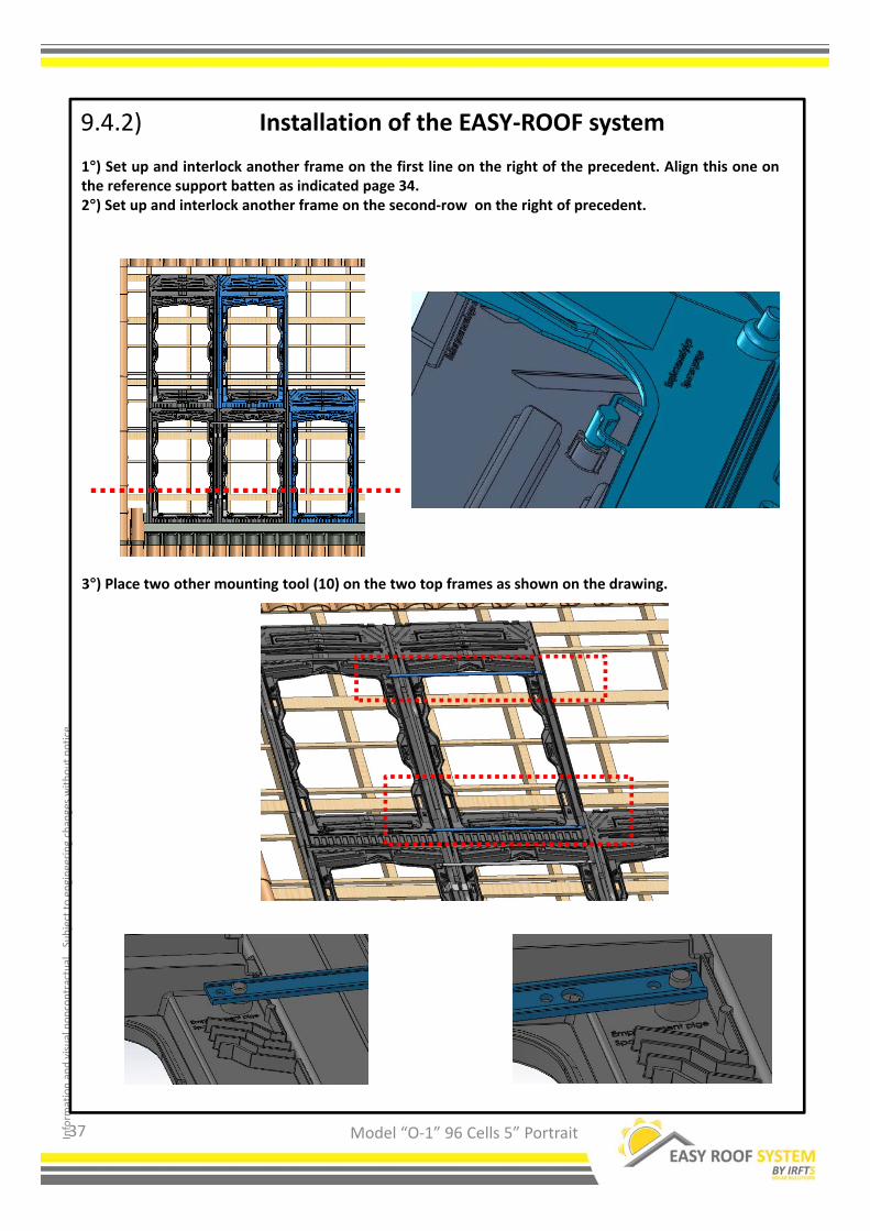
Installation of the EASY‐ROOF system
1°) Set up and interlock another frame on the first line on the right of the precedent. Align this one onthe reference support batten as indicated page 34.2°) Set up and interlock another frame on the second‐row on the right of precedent.
3°) Place two other mounting tool (10) on the two top frames as shown on the drawing.
37
9.4.2)
Inform
ation and visual noncontractual.Subject to engineering changes without notice.
Model “O‐1” 96 Cells 5” Portrait
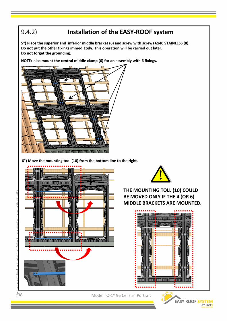
Installation of the EASY‐ROOF system
5°) Place the superior and inferior middle bracket (6) and screw with screws 6x40 STAINLESS (8).Do not put the other fixings immediately. This operation will be carried out later.Do not forget the grounding.
NOTE: also mount the central middle clamp (6) for an assembly with 6 fixings.
6°) Move the mounting tool (10) from the bottom line to the right.
THE MOUNTING TOLL (10) COULD BE MOVED ONLY IF THE 4 (OR 6) MIDDLE BRACKETS ARE MOUNTED.
38
9.4.2)

Inform
ation and visual noncontractual.Subject to engineering changes without notice.
Model “O‐1” 96 Cells 5” Portrait
Installation of the EASY‐ROOF system
7°) Set up and interlock all the other frames of the PV field by repeating the operations of pages35 to 38.
DO NOT PUT IN PLACES THE END BRACKET ON THE SYSTEM,THIS OPERATION WILL BE CARRIED OUT LATER AFTER THEPOSE OF THE SIDE FLASHING.
39
9.4.2)

Inform
ation and visual noncontractual.Subject to engineering changes without notice.
Model “O‐1” 96 Cells 5” Portrait
9.4.3) Installation of system EASY‐ROOF
a°) Interlock the pin of the second flashing in thefirst one.
b°) Rotate the second flashing.
c°) Clip the second flashing with the other.
2°) Set up the others one, they interlock eachother (See opposite).
Flashings assembly
1°) Position the first left flashing beside thefirst frame.
d°) Optional : Clip the frieze support at the topof the last flashing.
40

Inform
ation and visual noncontractual.Subject to engineering changes without notice.
Model “O‐1” 96 Cells 5” Portrait
9.4.3) Installation of the EASY‐ROOF system3°) Slightly lift the frames on the left, to drag the row of flashings under the frames.
4°) Align the last flashing with the top of the frame.
5°) At the bottom of the field cut the part of flashing which exceeds the frame if necessary.
6°) Set up a screw convex head 5x30 stainless (b) at each flashing overlap. Screw moderately.
7°) Set up a screw convex head 5x30 stainless (b) centered on the oblong hole. Screw moderately. VERY
IMPORTANT, to unscrew one turn, that is useful for the dilation of the part.
8°) If there is no batten under the flashings overlap, add a batten under the overlap.
9°) Fix all left flashings by applying instructions 6.7 and 8.
41
DO NOT TOUCH THE BOTTOM FLASHING
Inform
ation and visual noncontractual.Subject to engineering changes without notice.
Model “O‐1” 96 Cells 5” Portrait
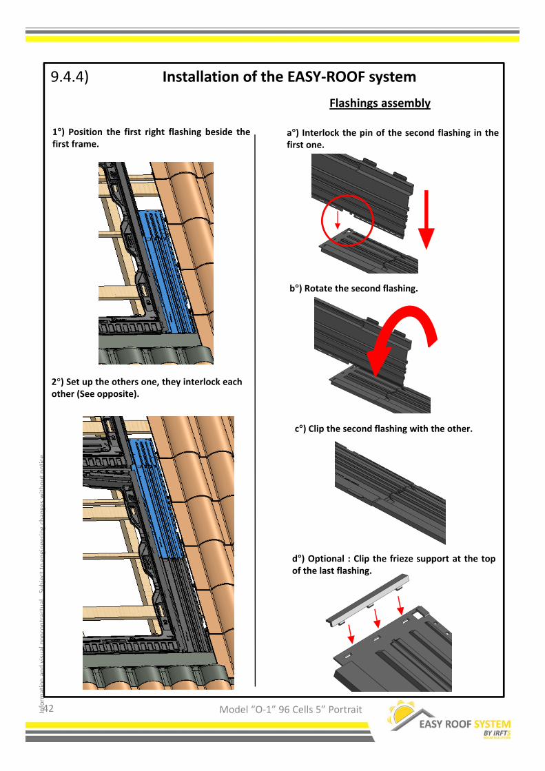
9.4.4) Installation of the EASY‐ROOF system
a°) Interlock the pin of the second flashing in thefirst one.
b°) Rotate the second flashing.
c°) Clip the second flashing with the other.
2°) Set up the others one, they interlock eachother (See opposite).
Flashings assembly
1°) Position the first right flashing beside thefirst frame.
d°) Optional : Clip the frieze support at the topof the last flashing.
42

Inform
ation and visual noncontractual.Subject to engineering changes without notice.
Model “O‐1” 96 Cells 5” Portrait
9.4.4) Installation of the EASY‐ROOF system
3°) Align the last flashing with the top of the frame. Place the ears of the flashings under the flexible flap
of the frames.
4°) At the bottom of the field cut the part of flashing which exceeds the frame if necessary.5°) Set up a screw convex head 5x30 stainless (b) at each flashing overlap. Screw moderately.
6°) Set up a screw convex head 5x30 stainless (b) centered on the oblong hole. Screw moderately. VERYIMPORTANT, to unscrew one turn, that is useful for the dilation of the part.7°) If there is no batten under the flashings overlap, add a batten under the overlap.
8°) Fix all right flashings by applying instructions 5.6 and 7.
43
DO NOT TOUCH THE BOTTOM FLASHING

Inform
ation and visual noncontractual.Subject to engineering changes without notice.
Model “O‐1” 96 Cells 5” Portrait
9.4.5)
Installation of the EASY‐ROOF system
Center the bracket in the vertical direction in the positioning hole(for dilation)
1°) Set up all the end bracket (7or 13) on the right of PV field. Interlock each end bracket in the openings
on the frames.2 or 3 end bracket (8) per frames according to the technical recommendations.Screw with screws 6x40 STAINLESS (8).
9.4.5)
1°) Set up all the end bracket (7 or 13) on the left of the PV field using a mounting tool (10) according tothe procedure describes hereafter.
THE USE OF A MOUNTING TOOL IS MANDATORY FOR THE INSTALLATION OF THE END BRACKET ON THE LEFT SIDE OF THE PV FIELD.
44
Minimum play 15 mm
Minimum play 15 mm
Inform
ation and visual noncontractual.Subject to engineering changes without notice.
Model “O‐1” 96 Cells 5” Portrait
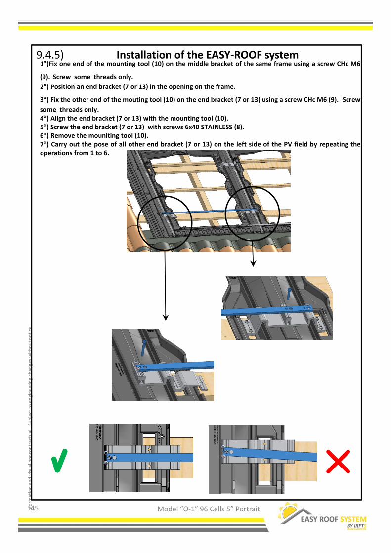
Installation of the EASY‐ROOF system1°)Fix one end of the mounting tool (10) on the middle bracket of the same frame using a screw CHc M6
(9). Screw some threads only.
2°) Position an end bracket (7 or 13) in the opening on the frame.
3°) Fix the other end of the mouting tool (10) on the end bracket (7 or 13) using a screw CHc M6 (9). Screw
some threads only.4°) Align the end bracket (7 or 13) with the mounting tool (10).5°) Screw the end bracket (7 or 13) with screws 6x40 STAINLESS (8).6°) Remove the mouniting tool (10).7°) Carry out the pose of all other end bracket (7 or 13) on the left side of the PV field by repeating theoperations from 1 to 6.
9.4.5)
45

Inform
ation and visual noncontractual.Subject to engineering changes without notice.
Model “O‐1” 96 Cells 5” Portrait
9.5) Installation of the EASY‐ROOF system
1°) Position the photovoltaic modules. For grounding, see page 48.
2°) Position the middle clamp (5 or 11) with the module wedge above the middle bracket between twomodule, the clamp leaning against the PV modules.3°) Slide the clamp downwards to interlok it on the middle bracket.
4°) Push the modules against the module wedge.5°) Before tightening, raise approximately 3 mm Miniumu the PV so that it is not any more leaning on itsown weight. VERY IMPORTANT, this play is necessary for dilation.
6°) Screw with a screw CHc M6 X 40 (9) according to the thickness of PV module.
Tightening torque 8.8 Nm(Local Cut on PV module)
3 mm
(Local Cut on PV module)
For PV modules with a short back frame, align thehigher edge of the module with the top point ofthe « leaning area » as shown on the drawing.
7°) Place all the middle bracket on the PV field
46

Inform
ation and visual noncontractual.Subject to engineering changes without notice.
Model “O‐1” 96 Cells 5” Portrait
9.5) Installation of the EASY‐ROOF system
1°) Adjust the height of the screws on the end bracket so that they are flush with the top of the PVmodule.
2°) Fix the PV modules with the end clamps (4 or 12) using screws CHc M6 X 40 (9).
PV module
(Cross‐section)
(End bracket)
(End clamp)
Tightening torque 8.8 Nm
47

Inform
ation and visual noncontractual.Subject to engineering changes without notice.
Model “O‐1” 96 Cells 5” Portrait
9.5.1) Grounding
If grounding is not done by connecting the ground wire directly to PV module, carry out the followingoperations.
1 °) Locate the middle bracket connected to the ground during the assembly.(see p. 36)
Length of the clamp
Make scratches here on the PV module
(view with local cut)
Scratch on PV module
Option 1°)Scratch the top of the PV module frame above the brackets connected to the ground. Thisensure connection to the ground via the screws located on clamp.
2°) Make sure then that connection between the PV module and the bracket(5 or 11) is less than 2 Ohms.
Option 2°)Place the claw on the back side of the PV module where it will lean so that it is restingagainst the mounting bracket connected to the ground.
48

Inform
ation and visual noncontractual.Subject to engineering changes without notice.
Model “O‐1” 96 Cells 5” Portrait
9.6) Put back the tiles
Put back the tiles, covering the top flashing up to he marking indicating “Limit tile”.
IMPORTANT: For the tiles with high profile, it is imperative to set up a self‐adhesivefoam band on the top flashing before replacing the tiles.
Dimension D
For the covering of the side flashings (2) and (3), the edge of the tiles have to be as close as possible to themarking indicating “Limit tile”.It is imperative that the dimension D does not exceed 40 mmMAXIMUM
Marking “Limits tile”
Marking “Limits tile”
49

Inform
ation and visual noncontractual.Subject to engineering changes without notice.
50
1°) Pull out the removable part at the top corner of the frame.
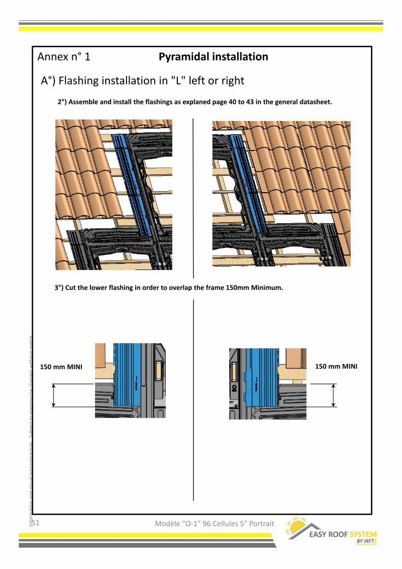
Annex n° 1 Pyramidal installation
A°) Flashing installation in "L" left or right
Modèle “O‐1” 96 Cellules 5" Portrait
Inform
ation and visual noncontractual.Subject to engineering changes without notice.
51
2°) Assemble and install the flashings as explaned page 40 to 43 in the general datasheet.
A°) Flashing installation in "L" left or right
Annex n° 1 Pyramidal installation
3°) Cut the lower flashing in order to overlap the frame 150mm Minimum.
150 mmMINI150 mmMINI
Modèle “O‐1” 96 Cellules 5" Portrait

Inform
ation and visual noncontractual.Subject to engineering changes without notice.
52
B°) Flashing installation in « T" left or right
Annex n° 1 Pyramidal installation
1°) Pull out the removable part at the bottom corner of the frame.
Modèle “O‐1” 96 Cellules 5" Portrait

Inform
ation and visual noncontractual.Subject to engineering changes without notice.
53
B°) Flashing installation in « T" left or right
Annex n° 1 Pyramidal installation
2°) Do the flooring for the bottom flashing, size the batten as describe in the general datasheetpage 19, 20 et 21.
200 mm
4°) Place the batten (K) at 200m from the frame (space needed for the flashing)
3°) The batten (E) and (G) should be long enough to support the flashing.
200 mm
Modèle “O‐1” 96 Cellules 5" Portrait

Inform
ation and visual noncontractual.Subject to engineering changes without notice.
54
B°) Flashing installation in « T" left or right
Annex n° 1 Pyramidal installation
6°) Assemble and place the flashing as describe in the general datasheet page 40 à 43.7°) Cut the exceeding part of the flashing in order to align with the bottom of the frame.
5°) Place the flashing like on the drawing below, respect the 15mm distance with the frame.
15 mm 15 mm
Modèle “O‐1” 96 Cellules 5" Portrait
Inform
ation and visual noncontractual.Subject to engineering changes without notice.
55
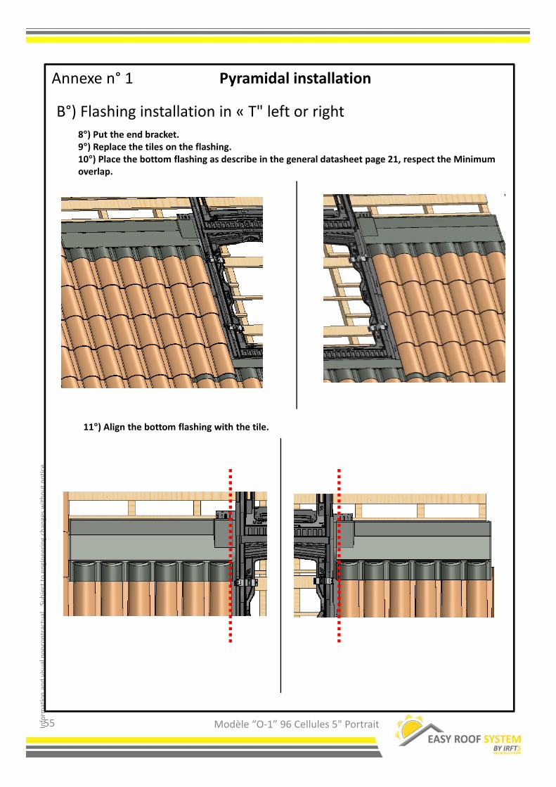
B°) Flashing installation in « T" left or right
Annexe n° 1 Pyramidal installation
11°) Align the bottom flashing with the tile.
8°) Put the end bracket.9°) Replace the tiles on the flashing.10°) Place the bottom flashing as describe in the general datasheet page 21, respect the Minimum overlap.
Modèle “O‐1” 96 Cellules 5" Portrait

Inform
ation and visual noncontractual.Subject to engineering changes without notice.
56
B°) Flashing installation in « T" left or right
Annexe n° 1 Pyramidal installation
12°) Put the superior frame and fix the other element as describe in the general datasheet.
Modèle “O‐1” 96 Cellules 5" Portrait
Inform
ation and visual noncontractual.Subject to engineering changes without notice.
10 mmMINI
57
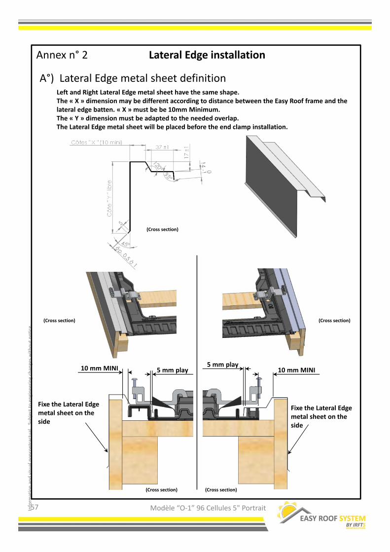
A°) Lateral Edge metal sheet definition
Annex n° 2 Lateral Edge installation
Left and Right Lateral Edge metal sheet have the same shape.The « X » dimension may be different according to distance between the Easy Roof frame and the lateral edge batten. « X » must be be 10mm Minimum.The « Y » dimension must be adapted to the needed overlap.The Lateral Edge metal sheet will be placed before the end clamp installation.
(Cross section) (Cross section)
(Cross section) (Cross section)
Fixe the Lateral Edgemetal sheet on the side
10 mm MINI5 mm play
5 mm play
Fixe the Lateral Edgemetal sheet on the side
(Cross section)
Modèle “O‐1” 96 Cellules 5" Portrait