Embed Size (px)
Citation preview
Revista da Associação Portuguesa de Análise Experimental de Tensões ISSN 1646-7078
Mecânica Experimental, 2013, Vol 22, Pgs 119-131 119
DAMPING RATIOS FOR POUNDING OF ADJACENT BUILDINGS AND THEIR CONSEQUENCE ON THE EVALUATION OF IMPACT
FORCES BY NUMERICAL AND EXPERIMENTAL MODELS
R. C. Barros, S. M. Khatami*
* Structural Division of Civil Engineering Department Faculty of Engineering (FEUP), University of Porto, Porto, Portugal
RESUMO
Neste artigo comparam-se os resultados das forças de impacto desenvolvidas entre duas estruturas adjacentes, usando diferentes modelos constitutivos de barras de ligação, para estudar e aferir o choque entre edifícios sob acção sísmica. Admite-se que os elementos de ligação permitem calcular as forças de impacto para vários modelos analíticos do contacto entre edifícios adjacentes sujeito a determinado acelerograma. No cálculo das forças de impacto considera-se que os elementos de ligação possuem um intervalo entre si, e só a partir desse valor a mola de elevada rigidez e o dispositivo amortecedor dispostos em paralelo, poderão funcionar. Neste estudo os diferentes elementos de ligação, desenvolvidos por investigadores e disponíveis na bibliografia, são utilizados e modificados para quantificar e comparar as forças de impacto entre duas estruturas modeladas. Para resolver as equações de equilíbrio dinâmico do movimento, um algoritmo numérico foi devidamente programado utilizando software MATLAB, sendo os resultados numéricos comparados graficamente. As equações e os modelos utilizados precisam ser melhorados para melhor avaliar as forças de impacto e permitir projectar edifícios adjacentes mais seguros. Apresenta-se uma equação alternativa para formulação do quociente de amortecimento, no contexto do modelo de Kelvin- Voigt, que pode fornecer uma das melhores estimativas da força de impacto. Nesse sentido também se apresenta um modelo experimental, e se justifica a sua utilização futura, que permitirá posteriores análises de
comparação de resultados experimentais com resultados do modelo numérico.ABSTRACT
This article compares results of impact forces between two dynamic structural models using different link elements, to study and assess the building pounding under seismic excitation. It is assumed that link elements are developed to calculate the impact forces for some analytical models of the contact between adjacent buildings, during time history loading. To calculate the impact forces, the link elements are assumed to have – besides a gap – spring with high stiffness and dashpot damper, located parallel with each other. In this study, different link elements developed or used by past researchers are modified to measure the impact force between two modelled structures; also a comparison of the results from the analyses is illustrated. For this investigation, determination of the impact forces is possible for the link models considered, whenever lateral displacement exceeds the gap. In order to solve the dynamic equations of motion, a numerical algorithm was suitably programmed by using MATLAB software. Finally, the results of the numerical investigations are represented graphically for comparison. It seems that the equations used need to be improved to better assess the impact forces and allow designing safer adjacent buildings. Here, an alternative equation of damping ratio is used and suggested to better calculate the impact force, in the context of the Kelvin-Voigt model; it has been shown that suggested equation can provide one of the best estimations of the impact force. Also an experimental model is presented for further comparison analysis with the numerical model.
R. C. Barros, S. M. Khatami
120
1. INTRODUCTION
Building pounding, involves analyzing and assessing impacts between two adjacent buildings under seismic excitation. It has been an interesting and needed research topic in earthquake engineering during the last few decades, due to significant observed and reported building damage associated with pounding induced by earthquakes. When adjacent buildings are not separated suitably from each other, impact forces can cause damage to buildings even if each individual structure is well-designed. Unfortunately, not enough attention has been paid to the building pounding effects in design codes. However, several researchers have tried to investigate the effects of such collisions worldwide. Anagnostopolos [1], Cole and Dhakal [2], Komodromos and Polycarpou [3], Jankowski [4] and Ye et al. [5], among many others, have modeled and analyzed building pounding by numerical investigations, using different models of link elements and also different formulas for characterizing the damping coefficient of the dashpot in the link element. In this article, useful contextualization of the background on pounding is provided and a new damping ratio estimation formula is suggested, that enable an improved calculation of the impact force and of the dissipated energy.
2. LINK ELEMENTS
Investigation of building pounding can be addressed in two different paths: experimental analyses and analytical analyses. To measure the impact force during collisions and lateral displacement of adjacent structures, software used need to define a specific link element at the connection level between the buildings analyzed. These link elements can be significantly different in order to insure complete matching results between analytical and experimental analyses based on the kind of link elements used. The mathematical equations corresponding to the modeling by distinct link elements are also able to calculate by different
approaches the impact forces during pounding. The main different concepts used on link elements correspond to appropriate use of gap, spring and damper in the link elements. Different types of springs with different stiffness or various dampers with different damping ratio have also been used in recent numerical studies at FEUP by Cordeiro [6] and by Vasconcelos [7], in their parametric studies of pounding between adjacent buildings. As periods of the adjacent colliding buildings are conceptually different, the link elements should be able to allow and translate the different behavior of buildings during seismic excitations.
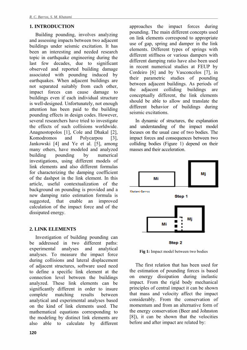
In dynamic of structures, the explanation and understanding of the impact model focuses on the usual case of two bodies. The impact forces and consequences between two colliding bodies (Figure 1) depend on their masses and their acceleration.
Fig 1: Impact model between two bodies
The first relation that has been used for the estimation of pounding forces is based on energy dissipation during inelastic impact. From the rigid body mechanical principles of central impact it can be shown that mass and velocity affect the impact considerably. From the conservation of momentum and from an alternative form of the energy conservation (Beer and Johnston [8]), it can be shown that the velocities before and after impact are related by:
Damping ratios for pounding of adjacent buildings and their consequence on the evaluation of impact forces by numerical and experimental models
121
= - (1+e) ( - ) (1)
= - (1+e) ( - ) (2)
where is the initial velocity of building number one, and denotes the initial velocity of building number two. In these equations, and also denote the final velocities of buildings after collision, respectively. and are object masses of buildings, which are here considered as modeled by lumped masses.
Finally, e denotes the coefficient of restitution which is the ratio between the relative velocity post-collision and the relative velocity before-collision. This variable takes values between 0 and 1, whose extreme values represent elastic or plastic behavior.
If e=1, the collision is completely elastic; on the other hand if e=0, then the collision is completely plastic and the two colliding masses end up with the same final velocity since they remain in contact. Usually the value of e=0.65 has been recommended by the majority of researchers, for the inherent inelastic collision associated with the pounding of adjacent buildings and structures.
2.1. Linear Elastic Model
The first investigated model is based on a linear impact spring, which provides an elastic impact force on the link element and simulates impact force using linear curve stiffness. The equation of the contact collision force during pounding, evaluated by the linear elastic model, is given by:
(t)= .δ(t) (3)
where is the stiffness of the linear impact spring and δ(t) denotes the lateral displacement of the colliding bodies that overlap each other at time t.
Fig 2: Linear elastic model
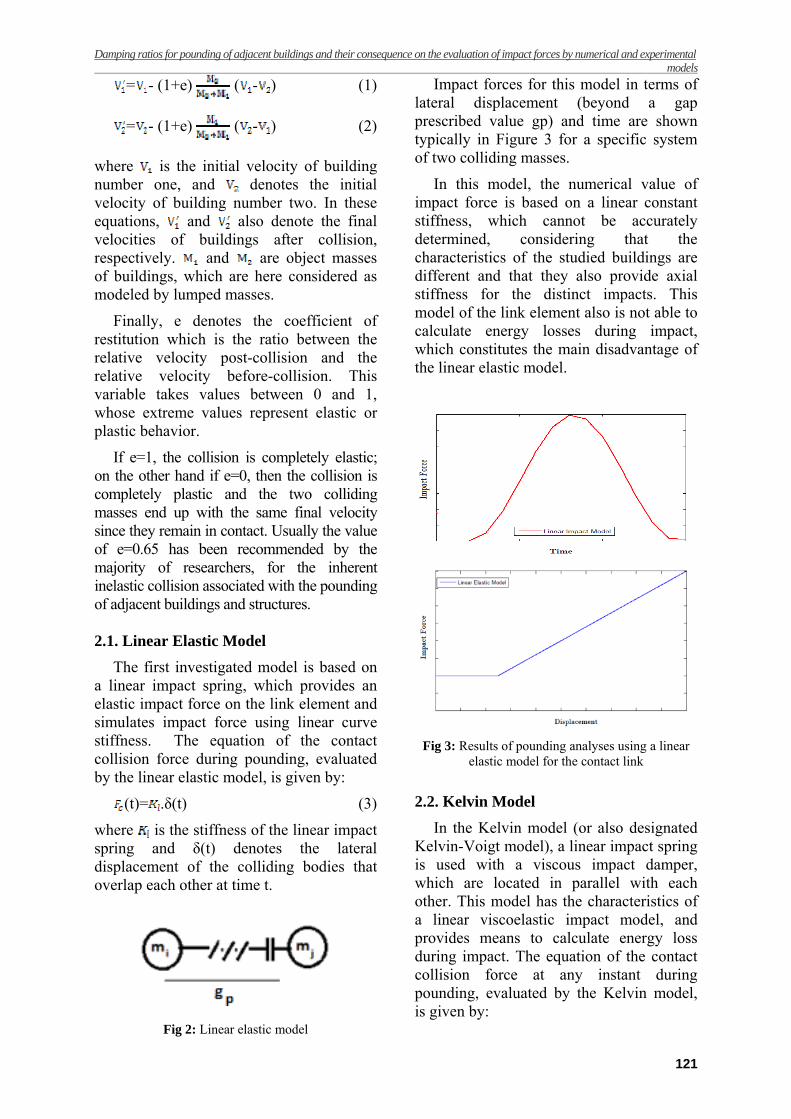
Impact forces for this model in terms of lateral displacement (beyond a gap prescribed value gp) and time are shown typically in Figure 3 for a specific system of two colliding masses.
In this model, the numerical value of impact force is based on a linear constant stiffness, which cannot be accurately determined, considering that the characteristics of the studied buildings are different and that they also provide axial stiffness for the distinct impacts. This model of the link element also is not able to calculate energy losses during impact, which constitutes the main disadvantage of the linear elastic model.
Fig 3: Results of pounding analyses using a linear elastic model for the contact link
2.2. Kelvin Model
In the Kelvin model (or also designated Kelvin-Voigt model), a linear impact spring is used with a viscous impact damper, which are located in parallel with each other. This model has the characteristics of a linear viscoelastic impact model, and provides means to calculate energy loss during impact. The equation of the contact collision force at any instant during pounding, evaluated by the Kelvin model, is given by:
R. C. Barros, S. M. Khatami
122
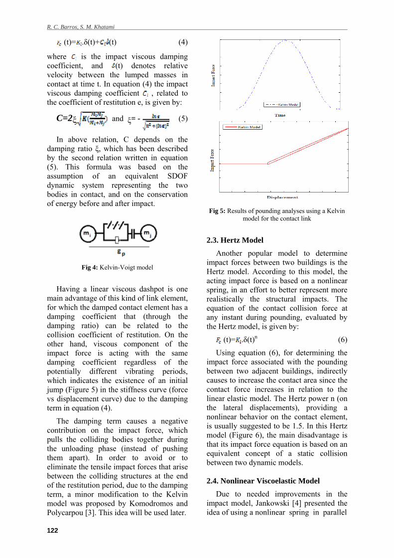
(t)= .δ(t)+ (t) (4)
where is the impact viscous damping coefficient, and (t) denotes relative velocity between the lumped masses in contact at time t. In equation (4) the impact viscous damping coefficient , related to the coefficient of restitution e, is given by:
C=2ξ and ξ= - (5)
In above relation, C depends on the damping ratio ξ, which has been described by the second relation written in equation (5). This formula was based on the assumption of an equivalent SDOF dynamic system representing the two bodies in contact, and on the conservation of energy before and after impact.
Fig 4: Kelvin-Voigt model
Having a linear viscous dashpot is one main advantage of this kind of link element, for which the damped contact element has a damping coefficient that (through the damping ratio) can be related to the collision coefficient of restitution. On the other hand, viscous component of the impact force is acting with the same damping coefficient regardless of the potentially different vibrating periods, which indicates the existence of an initial jump (Figure 5) in the stiffness curve (force vs displacement curve) due to the damping term in equation (4).
The damping term causes a negative contribution on the impact force, which pulls the colliding bodies together during the unloading phase (instead of pushing them apart). In order to avoid or to eliminate the tensile impact forces that arise between the colliding structures at the end of the restitution period, due to the damping term, a minor modification to the Kelvin model was proposed by Komodromos and Polycarpou [3]. This idea will be used later.
Fig 5: Results of pounding analyses using a Kelvin model for the contact link
2.3. Hertz Model
Another popular model to determine impact forces between two buildings is the Hertz model. According to this model, the acting impact force is based on a nonlinear spring, in an effort to better represent more realistically the structural impacts. The equation of the contact collision force at any instant during pounding, evaluated by the Hertz model, is given by:
(t)= .δ(t)n (6)
Using equation (6), for determining the impact force associated with the pounding between two adjacent buildings, indirectly causes to increase the contact area since the contact force increases in relation to the linear elastic model. The Hertz power n (on the lateral displacements), providing a nonlinear behavior on the contact element, is usually suggested to be 1.5. In this Hertz model (Figure 6), the main disadvantage is that its impact force equation is based on an equivalent concept of a static collision between two dynamic models. 2.4. Nonlinear Viscoelastic Model
Due to needed improvements in the impact model, Jankowski [4] presented the idea of using a nonlinear spring in parallel
Damping ratios for pounding of adjacent buildings and their consequence on the evaluation of impact forces by numerical and experimental models
123
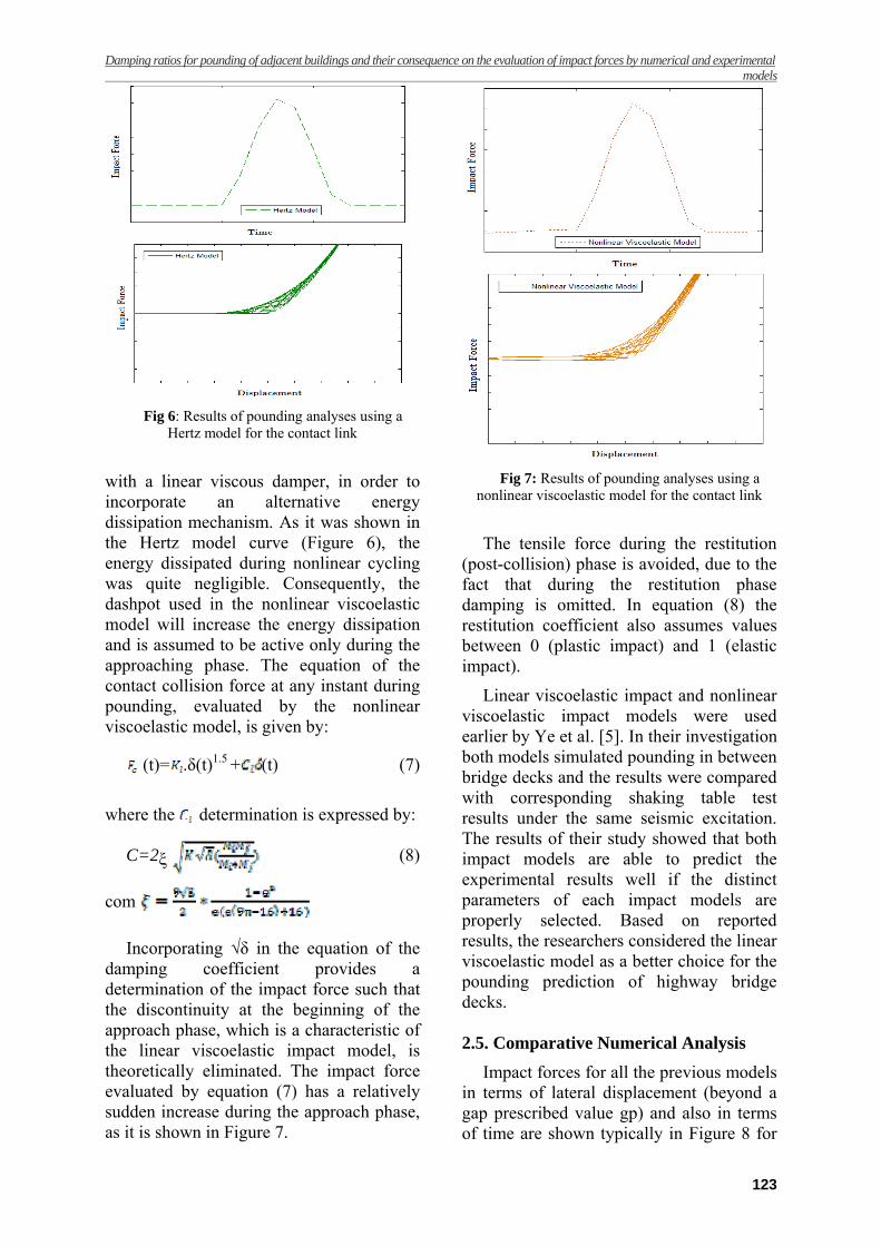
Fig 6: Results of pounding analyses using a Hertz model for the contact link
with a linear viscous damper, in order to incorporate an alternative energy dissipation mechanism. As it was shown in the Hertz model curve (Figure 6), the energy dissipated during nonlinear cycling was quite negligible. Consequently, the dashpot used in the nonlinear viscoelastic model will increase the energy dissipation and is assumed to be active only during the approaching phase. The equation of the contact collision force at any instant during pounding, evaluated by the nonlinear viscoelastic model, is given by:
(t)= .δ(t)1.5 + (t) (7)
where the determination is expressed by:
C=2ξ (8)
com
Incorporating √δ in the equation of the damping coefficient provides a determination of the impact force such that the discontinuity at the beginning of the approach phase, which is a characteristic of the linear viscoelastic impact model, is theoretically eliminated. The impact force evaluated by equation (7) has a relatively sudden increase during the approach phase, as it is shown in Figure 7.
Fig 7: Results of pounding analyses using a nonlinear viscoelastic model for the contact link
The tensile force during the restitution (post-collision) phase is avoided, due to the fact that during the restitution phase damping is omitted. In equation (8) the restitution coefficient also assumes values between 0 (plastic impact) and 1 (elastic impact).
Linear viscoelastic impact and nonlinear viscoelastic impact models were used earlier by Ye et al. [5]. In their investigation both models simulated pounding in between bridge decks and the results were compared with corresponding shaking table test results under the same seismic excitation. The results of their study showed that both impact models are able to predict the experimental results well if the distinct parameters of each impact models are properly selected. Based on reported results, the researchers considered the linear viscoelastic model as a better choice for the pounding prediction of highway bridge decks.
2.5. Comparative Numerical Analysis
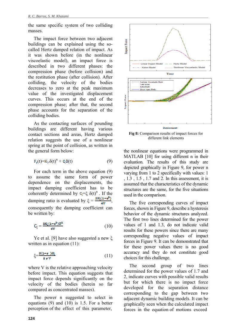
Impact forces for all the previous models in terms of lateral displacement (beyond a gap prescribed value gp) and also in terms of time are shown typically in Figure 8 for
R. C. Barros, S. M. Khatami
124
the same specific system of two colliding masses.
The impact force between two adjacent buildings can be explained using the so-called Hertz damped relation of impact. As it was shown before (in the nonlinear viscoelastic model), an impact force is described in two different phases: the compression phase (before collision) and the restitution phase (after collision). After colliding, the velocity of the bodies decreases to zero at the peak maximum value of the investigated displacement curves. This occurs at the end of the compression phase; after that, the second phase accounts for the separation of the colliding bodies.
As the contacting surfaces of pounding buildings are different having various contact sections and areas, Hertz damped relation suggests the use of a nonlinear spring at the point of collision, as written in the general form below:
(t)= .δ(t)n + (t) (9)
For each term in the above equation (9) to assume the same form of power dependence on the displacements, the impact damping coefficient has to be coherently determined by =ξ δ(t)n . If the
damping ratio is evaluated by ξ = ,
consequently the damping coefficient can be written by:
= (10)
Ye et al. [9] have also suggested a new ξ written as in equation (11):
ξ= (11)
where V is the relative approaching velocity before impact. This equation suggests that impact force depends significantly on the velocity of the bodies (herein so far compared as concentrated masses).
The power n suggested to select in equations (9) and (10) is 1.5. For a better perception of the effect of this parameter,
Fig 8: Comparison results of impact forces for
different link elements
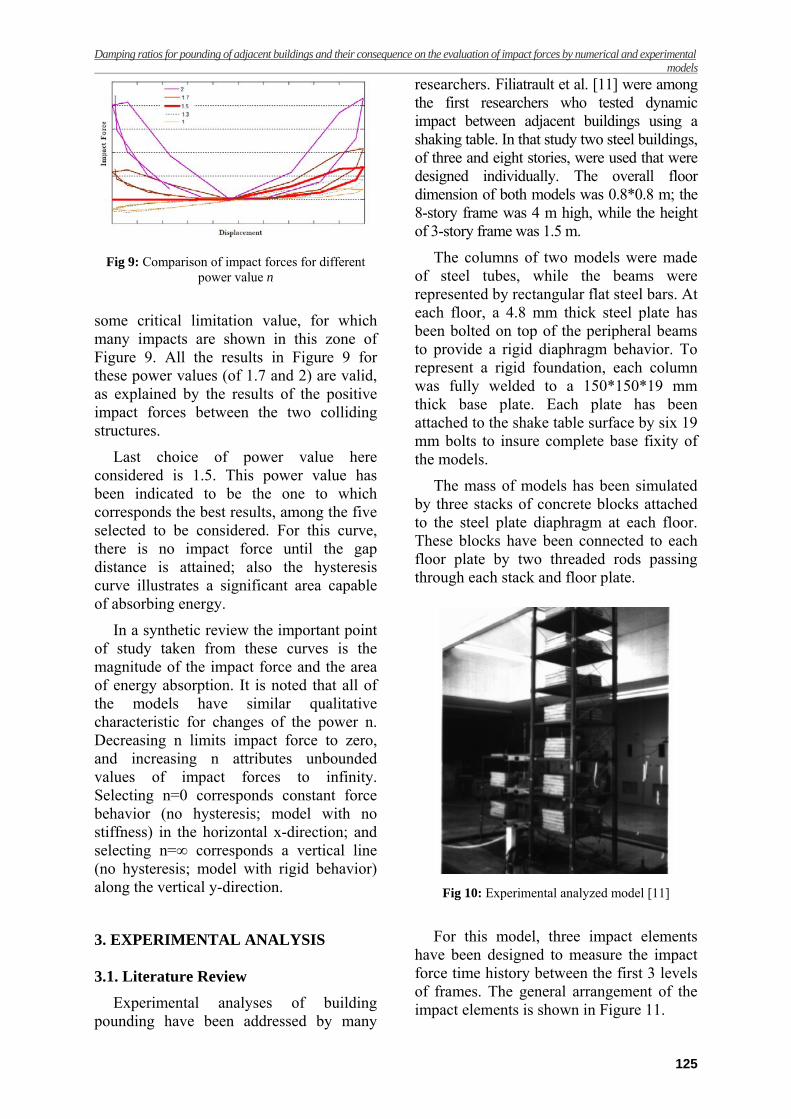
the nonlinear equations were programmed in MATLAB [10] for using different n in their evaluation. The results of this study are depicted graphically in Figure 9, for power n varying from 1 to 2 specifically with values: 1 , 1.3 , 1.5 , 1.7 and 2. In this assessment, it is assumed that the characteristics of the dynamic structures are the same, for the five situations used in the comparison.
The five corresponding curves of impact forces, shown in Figure 9, describe a hysteresis behavior of the dynamic structures analyzed. The first two lines determined for the power values of 1 and 1.3, do not indicate valid results for these powers since there are many corresponding negative values of impact forces in Figure 9. It can be demonstrated that for these power values there is no good accuracy and they do not constitute good choices for this challenge.
The second group of two lines determined for the power values of 1.7 and 2, indicate curves with possible valid results but for which there is no impact force developed for the separation distance corresponding to the gap between two adjacent dynamic building models. It can be graphically seen when the calculated impact forces in the equation of motions exceed
Damping ratios for pounding of adjacent buildings and their consequence on the evaluation of impact forces by numerical and experimental models
125
Fig 9: Comparison of impact forces for different
power value n
some critical limitation value, for which many impacts are shown in this zone of Figure 9. All the results in Figure 9 for these power values (of 1.7 and 2) are valid, as explained by the results of the positive impact forces between the two colliding structures.
Last choice of power value here considered is 1.5. This power value has been indicated to be the one to which corresponds the best results, among the five selected to be considered. For this curve, there is no impact force until the gap distance is attained; also the hysteresis curve illustrates a significant area capable of absorbing energy.
In a synthetic review the important point of study taken from these curves is the magnitude of the impact force and the area of energy absorption. It is noted that all of the models have similar qualitative characteristic for changes of the power n. Decreasing n limits impact force to zero, and increasing n attributes unbounded values of impact forces to infinity. Selecting n=0 corresponds constant force behavior (no hysteresis; model with no stiffness) in the horizontal x-direction; and selecting n=∞ corresponds a vertical line (no hysteresis; model with rigid behavior) along the vertical y-direction.
3. EXPERIMENTAL ANALYSIS 3.1. Literature Review
Experimental analyses of building pounding have been addressed by many
researchers. Filiatrault et al. [11] were among the first researchers who tested dynamic impact between adjacent buildings using a shaking table. In that study two steel buildings, of three and eight stories, were used that were designed individually. The overall floor dimension of both models was 0.8*0.8 m; the 8-story frame was 4 m high, while the height of 3-story frame was 1.5 m.
The columns of two models were made of steel tubes, while the beams were represented by rectangular flat steel bars. At each floor, a 4.8 mm thick steel plate has been bolted on top of the peripheral beams to provide a rigid diaphragm behavior. To represent a rigid foundation, each column was fully welded to a 150*150*19 mm thick base plate. Each plate has been attached to the shake table surface by six 19 mm bolts to insure complete base fixity of the models.
The mass of models has been simulated by three stacks of concrete blocks attached to the steel plate diaphragm at each floor. These blocks have been connected to each floor plate by two threaded rods passing through each stack and floor plate.
Fig 10: Experimental analyzed model [11]
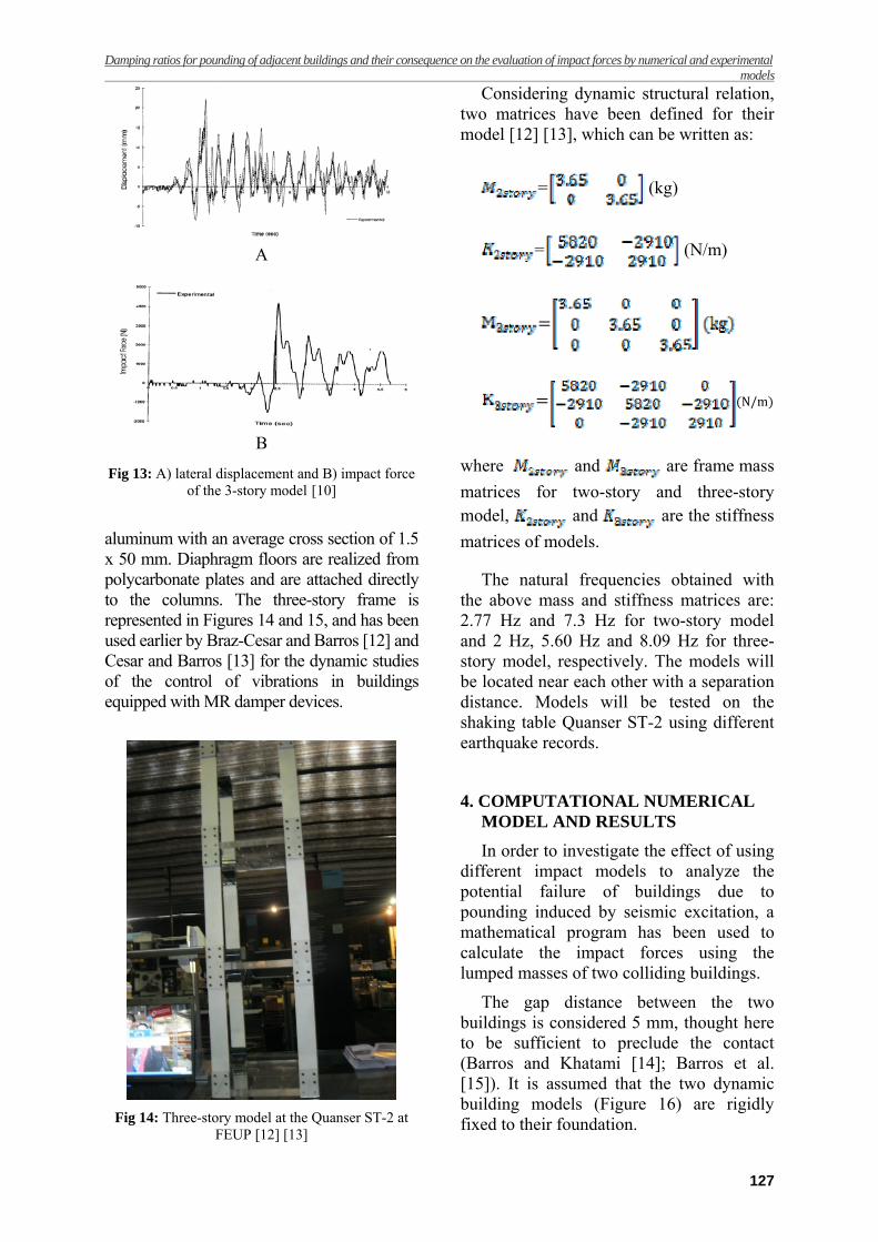
For this model, three impact elements have been designed to measure the impact force time history between the first 3 levels of frames. The general arrangement of the impact elements is shown in Figure 11.
R. C. Barros, S. M. Khatami
126
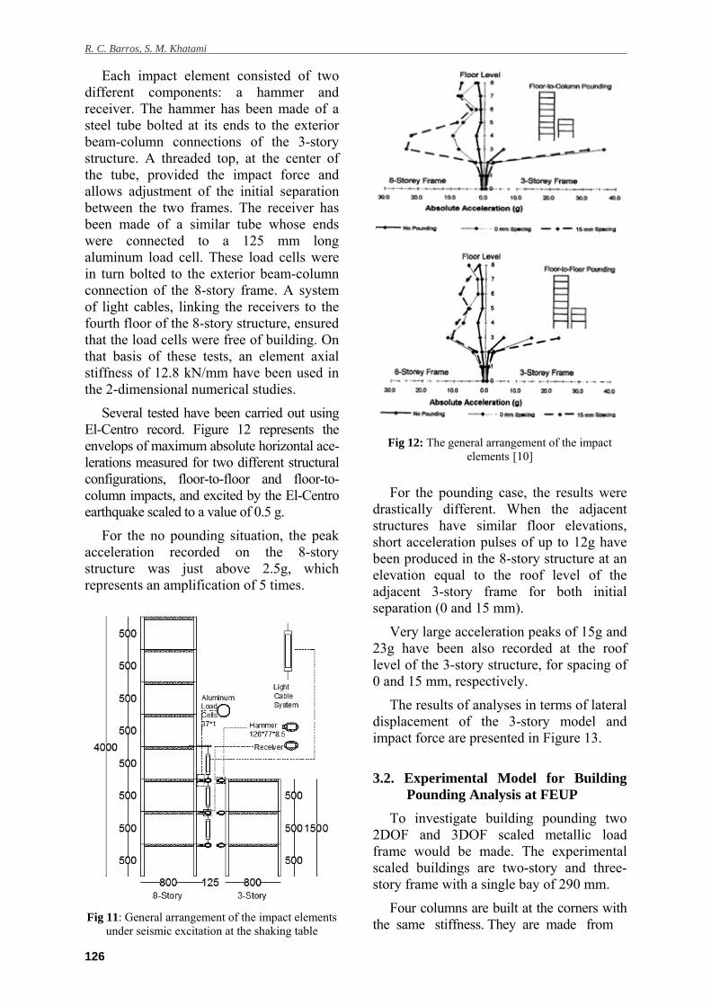
Each impact element consisted of two different components: a hammer and receiver. The hammer has been made of a steel tube bolted at its ends to the exterior beam-column connections of the 3-story structure. A threaded top, at the center of the tube, provided the impact force and allows adjustment of the initial separation between the two frames. The receiver has been made of a similar tube whose ends were connected to a 125 mm long aluminum load cell. These load cells were in turn bolted to the exterior beam-column connection of the 8-story frame. A system of light cables, linking the receivers to the fourth floor of the 8-story structure, ensured that the load cells were free of building. On that basis of these tests, an element axial stiffness of 12.8 kN/mm have been used in the 2-dimensional numerical studies.
Several tested have been carried out using El-Centro record. Figure 12 represents the envelops of maximum absolute horizontal ace-lerations measured for two different structural configurations, floor-to-floor and floor-to-column impacts, and excited by the El-Centro earthquake scaled to a value of 0.5 g.
For the no pounding situation, the peak acceleration recorded on the 8-story structure was just above 2.5g, which represents an amplification of 5 times.
Fig 11: General arrangement of the impact elements
under seismic excitation at the shaking table
Fig 12: The general arrangement of the impact elements [10]
For the pounding case, the results were drastically different. When the adjacent structures have similar floor elevations, short acceleration pulses of up to 12g have been produced in the 8-story structure at an elevation equal to the roof level of the adjacent 3-story frame for both initial separation (0 and 15 mm).
Very large acceleration peaks of 15g and 23g have been also recorded at the roof level of the 3-story structure, for spacing of 0 and 15 mm, respectively.
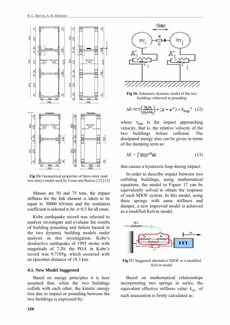
The results of analyses in terms of lateral displacement of the 3-story model and impact force are presented in Figure 13.
3.2. Experimental Model for Building
Pounding Analysis at FEUP
To investigate building pounding two 2DOF and 3DOF scaled metallic load frame would be made. The experimental scaled buildings are two-story and three-story frame with a single bay of 290 mm.
Four columns are built at the corners with the same stiffness. They are made from
Damping ratios for pounding of adjacent buildings and their consequence on the evaluation of impact forces by numerical and experimental models
127
A
B
Fig 13: A) lateral displacement and B) impact force of the 3-story model [10]
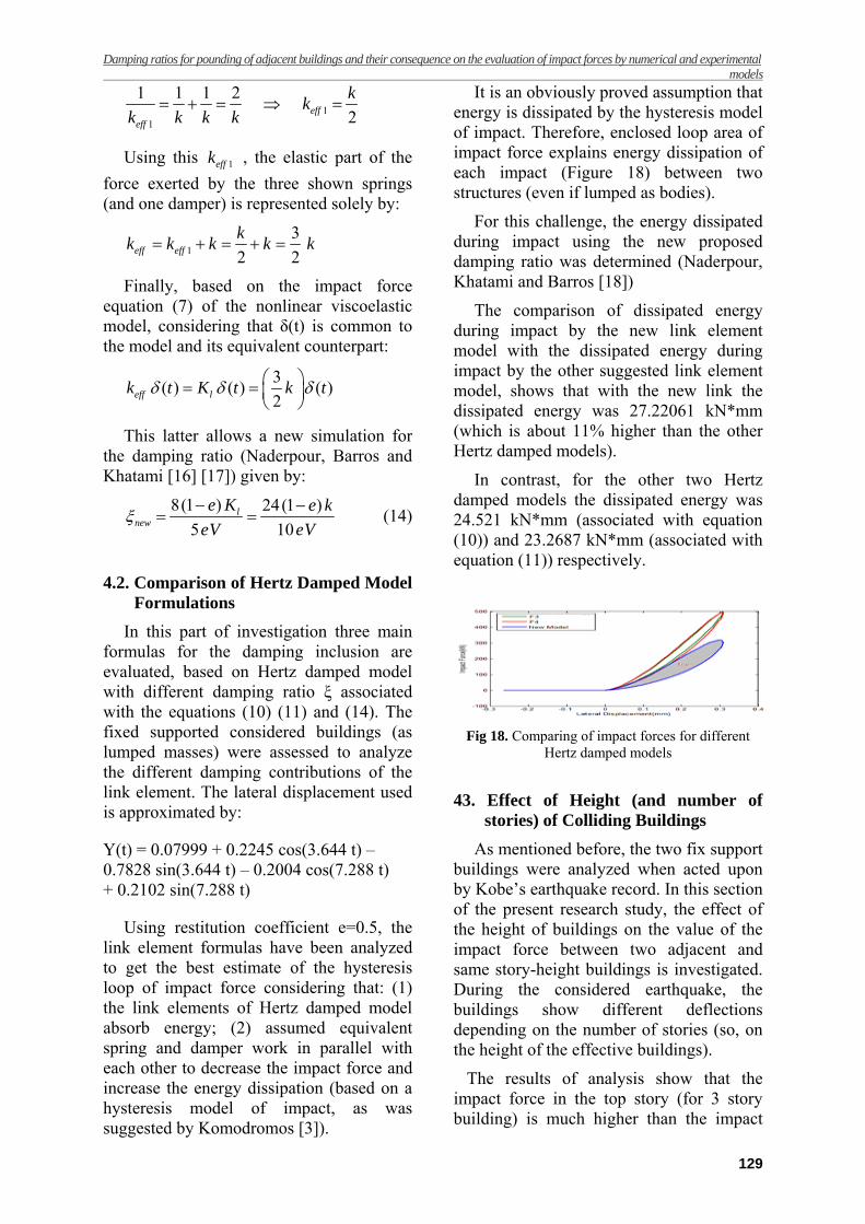
aluminum with an average cross section of 1.5 x 50 mm. Diaphragm floors are realized from polycarbonate plates and are attached directly to the columns. The three-story frame is represented in Figures 14 and 15, and has been used earlier by Braz-Cesar and Barros [12] and Cesar and Barros [13] for the dynamic studies of the control of vibrations in buildings equipped with MR damper devices.
Fig 14: Three-story model at the Quanser ST-2 at
FEUP [12] [13]
Considering dynamic structural relation, two matrices have been defined for their model [12] [13], which can be written as:
= (kg)
= (N/m)
N/m
where and are frame mass
matrices for two-story and three-story model, and are the stiffness
matrices of models.
The natural frequencies obtained with the above mass and stiffness matrices are: 2.77 Hz and 7.3 Hz for two-story model and 2 Hz, 5.60 Hz and 8.09 Hz for three-story model, respectively. The models will be located near each other with a separation distance. Models will be tested on the shaking table Quanser ST-2 using different earthquake records.
4. COMPUTATIONAL NUMERICAL MODEL AND RESULTS
In order to investigate the effect of using different impact models to analyze the potential failure of buildings due to pounding induced by seismic excitation, a mathematical program has been used to calculate the impact forces using the lumped masses of two colliding buildings.
The gap distance between the two buildings is considered 5 mm, thought here to be sufficient to preclude the contact (Barros and Khatami [14]; Barros et al. [15]). It is assumed that the two dynamic building models (Figure 16) are rigidly fixed to their foundation.
R. C. Barros, S. M. Khatami
128
Fig 15: Geometrical properties of three-story (and
two-story) model used by Cesar and Barros [12] [13]
Masses are 50 and 75 tons, the impact stiffness for the link element is taken to be equal to 30000 kN/mm and the restitution coefficient is selected to be e=0.5 for all cases.
Kobe earthquake record was selected to analyze investigate and evaluate the results of building pounding and failure hazard in the two dynamic building models under analysis in this investigation. Kobe’s destructive earthquake of 1995 stroke with magnitude of 7.20; the PGA in Kobe’s record was 0.7105g, which occurred with an epicenter distance of 18.3 km.
4.1. New Model Suggested
Based on energy principles it is here assumed that, when the two buildings collide with each other, the kinetic energy loss due to impact or pounding between the two buildings is expressed by:
Fig 16: Schematic dynamic model of the two
buildings subjected to pounding
∆E=0.5 (12)
where is the impact approaching velocity, that is, the relative velocity of the two buildings before collision. The dissipated energy also can be given in terms of the damping term as:
∆E = (13)
that causes a hysteresis loop during impact.
In order to describe impact between two colliding buildings, using mathematical equations, the model in Figure 17 can be equivalently solved to obtain the response of such SDOF system. In this model, using three springs with same stiffness and damper, a new improved model is achieved as a modified Kelvin model.
Fig 17: Suggested alternative SDOF as a modified
Kelvin model
Based on mathematical relationships incorporating two springs in series, the equivalent effective stiffness value 1effk of
such association is firstly calculated as:
Damping ratios for pounding of adjacent buildings and their consequence on the evaluation of impact forces by numerical and experimental models
129
11
1 1 1 2
2effeff
kk
k k k k
Using this 1effk , the elastic part of the
force exerted by the three shown springs (and one damper) is represented solely by:
1
3
2 2eff eff
kk k k k k
Finally, based on the impact force equation (7) of the nonlinear viscoelastic model, considering that δ(t) is common to the model and its equivalent counterpart:
3( ) ( ) ( )
2eff lk t K t k t
This latter allows a new simulation for the damping ratio (Naderpour, Barros and Khatami [16] [17]) given by:
8(1 ) 24(1 )
5 10l
new
e K e k
eV eV
(14)
4.2. Comparison of Hertz Damped Model
Formulations
In this part of investigation three main formulas for the damping inclusion are evaluated, based on Hertz damped model with different damping ratio ξ associated with the equations (10) (11) and (14). The fixed supported considered buildings (as lumped masses) were assessed to analyze the different damping contributions of the link element. The lateral displacement used is approximated by:
Y(t) = 0.07999 + 0.2245 cos(3.644 t) – 0.7828 sin(3.644 t) – 0.2004 cos(7.288 t) + 0.2102 sin(7.288 t)
Using restitution coefficient e=0.5, the link element formulas have been analyzed to get the best estimate of the hysteresis loop of impact force considering that: (1) the link elements of Hertz damped model absorb energy; (2) assumed equivalent spring and damper work in parallel with each other to decrease the impact force and increase the energy dissipation (based on a hysteresis model of impact, as was suggested by Komodromos [3]).
It is an obviously proved assumption that energy is dissipated by the hysteresis model of impact. Therefore, enclosed loop area of impact force explains energy dissipation of each impact (Figure 18) between two structures (even if lumped as bodies).
For this challenge, the energy dissipated during impact using the new proposed damping ratio was determined (Naderpour, Khatami and Barros [18])
The comparison of dissipated energy during impact by the new link element model with the dissipated energy during impact by the other suggested link element model, shows that with the new link the dissipated energy was 27.22061 kN*mm (which is about 11% higher than the other Hertz damped models).
In contrast, for the other two Hertz damped models the dissipated energy was 24.521 kN*mm (associated with equation (10)) and 23.2687 kN*mm (associated with equation (11)) respectively.
Fig 18. Comparing of impact forces for different
Hertz damped models
43. Effect of Height (and number of
stories) of Colliding Buildings
As mentioned before, the two fix support buildings were analyzed when acted upon by Kobe’s earthquake record. In this section of the present research study, the effect of the height of buildings on the value of the impact force between two adjacent and same story-height buildings is investigated. During the considered earthquake, the buildings show different deflections depending on the number of stories (so, on the height of the effective buildings).
The results of analysis show that the impact force in the top story (for 3 story building) is much higher than the impact
R. C. Barros, S. M. Khatami
130
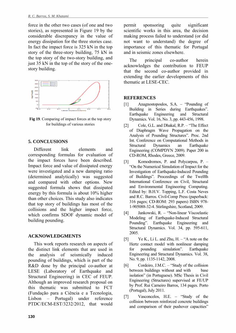
force in the other two cases (of one and two stories), as represented in Figure 19 by the considerable discrepancy in the value of energy dissipation for the three stories case. In fact the impact force is 325 kN in the top story of the three-story building, 75 kN in the top story of the two-story building, and just 35 kN in the top of the story of the one-story building.
Fig 19. Comparing of impact forces at the top story
for buildings of various stories
5. CONCLUSIONS
Different link elements and corresponding formulas for evaluation of the impact forces have been described. Impact force and value of dissipated energy were investigated and a new damping ratio (determined analytically) was suggested and compared with other options. New suggested formula shows that dissipated energy by this formula is about 10% higher than other choices. This study also indicates that top story of buildings has most of the collisions and the higher impact force, which confirms SDOF dynamic model of building pounding.
ACKNOWLEDGMENTS
This work reports research on aspects of the distinct link elements that are used in the analysis of seismically induced pounding of buildings, which is part of the R&D done by the principal co-author at LESE (Laboratory of Earthquake and Structural Engineering) in CEC of FEUP. Although an improved research proposal on this thematic was submitted to FCT (Fundação para a Ciência e a Tecnologia, Lisbon – Portugal) under reference PTDC/ECM-EST/3232/2012, that would
permit sponsoring quite significant scientific works in this area, the decision making process failed to understand (or did not want to understand) the degree of importance of this thematic for Portugal and in seismic zones elsewhere.
The principal co-author herein acknowledges the contribution to FEUP that the second co-author provided in extending the earlier developments of this thematic at LESE-CEC.
REFERENCES [1] Anagnostopoulos, S.A. – “Pounding of
Building in Series during Earthquakes”. Earthquake Engineering and Structural Dynamics. Vol. 16, No. 3, pp. 443-456, 1998.
[2] Cole, G.L. and Dhakal, R.P. – “The Effect of Diaphragm Wave Propagation on the Analysis of Pounding Structures”. Proc. 2nd Int. Conference on Computational Methods in Structural Dynamics an Earthquake Engineering (COMPDYN 2009). Paper 200 in CD-ROM, Rhodes, Greece, 2009.
[3] Komodromos, P. and Polycarpou, P. – “On the Numerical Simulation of Impact for the Investigation of Earthquake-Induced Pounding of Buildings”. Proceedings of the Twelfth International Conference on Civil, Structural and Environmental Engineering Computing. Edited by: B.H.V. Topping, L.F. Costa Neves and R.C. Barros. Civil-Comp Press (paperback: 316 pages; CD-ROM: 293 papers) ISBN 978-1-905088-32-4. Stirlingshire, Scotland, 2009.
[4] Jankowski, R. – “Non-linear Viscoelastic Modeling of Earthquake-Induced Structural Pounding”. Earthquake Engineering and Structural Dynamics. Vol. 34, pp. 595-611, 2005.
[5] Ye K., Li L. and Zhu, H. – “A note on the Hertz contact model with nonlinear damping for pounding simulation”. Earthquake Engineering and Structural Dynamics. Vol. 38, No. 9, pp. 1135-1142, 2008.
[6] Cordeiro, J.M.C. – “Study of the collision between buildings without and with base isolation” (in Portuguese). MSc Thesis in Civil Engineering (Structures) supervised at FE/UP by Prof. Rui Carneiro Barros, 134 pages. Porto (Portugal), July 2011.
[7] Vasconcelos, H.E. – “Study of the collision between reinforced concrete buildings and comparison of their pushover capacities”
Damping ratios for pounding of adjacent buildings and their consequence on the evaluation of impact forces by numerical and experimental models
131
(in Portuguese). MSc Thesis in Civil Engineering (Structures) supervised at FE/UP by Prof. Rui Carneiro Barros, 103 pages. Porto (Portugal), July 2011.
[8] Beer, F.P. and Johnston, E.R. – Vector Mechanics for Engineers: Statics and Dynamics, McGraw-Hill Book Company, 6th edition, New York, 2000.
[9] Ye K., Li L. and Zhu H. – “A modified Kelvin impact model for pounding simulation of base-isolated building with adjacent structures”. Earthquake Engineering and Engineering Vibration. Vol. 8, No. 3, pp. 433-446, 2009.
[10] MATLAB, The Language of Technical Computing, Version 2010 a.
[11] Filiatrault A., Wagner P., Cherry S. – “An experimental study on the seismic pounding of buildings”. Eleventh World Conference on Earthquake Engineering. Paper No. 210, Elseviere Science Ltd, 1996.
[12] Braz-Cesar, M.T. and Barros, R. – “Semi-Active Control of a Metallic Scaled Frame with a MR Damper: Numerical and Experimental Research”. In book: School and Symposium on Smart Structural Systems Technologies, Editors: R. Barros and A. Preumont, ISBN: 978-989-96697-0-3, pp. 419-440, FEUP and ESF, Porto, 2010.
[13] Cesar, M.B. and Barros, R.C. – “Semi-Active Vibration Control of a 3-DOF Scaled Frame with a Magneto-Rheological Damper”. Proceedings of the Tenth International Conference on Computational Structures Technology, Editors: B.H.V. Topping, J.M. Adam, F.J. Pallarés, R. Bru and M.L. Romero. ISBN 978-1-905088-36-2, Civil-Comp Press, Stirlingshire, UK, 2010, doi:10.4203/ccp.93.
[14] Barros, R.C. and Khatami, S.M. – “Importance of Separation Distance on Building Pounding under Near-Fault Ground Motion, Using the Iranian Earthquake Code”. 9th International Congress on Civil Engineering. 9 ICCE: May 8-10, 2012. Isfahan University of Technology (IUT), Isfahan, Iran.
[15] Barros R.C., Naderpour H., Khatami S.M. and Mortezaei A. – “Influence of Seismic Pounding on RC Buildings with and without Base Isolation System Subject to Near-Fault Ground Motions”. Journal of Rehabilitation in Civil Engineering, Vol. 1, Issue 1, pp. 39-52, 2013.
[16] Naderpour H., Barros R.C. and Khatami S.M. – “A New Equation of Motion to Calculate the Impact Force and the Energy Dissipation”, Proceedings of the 14th International Conference on Civil Structural and Environmental Engineering Computing, B.H.V. Topping and P. Iványi (Editors). Cagliari–Sardinia–Italy, 3-6 September 2013. CD-ROM Paper 92.
[17] Naderpour H., Barros R.C. and Khatami S.M. – “Suggestion of a New Link Element to Calculate the Impact Force and Energy Dissipation Based on CR-Factor and Impact Velocity”. The Modares Journal of Civil Engineering, Volume 13, Nº 3, Autumn 2013, pp: 77-85 (in farsi).
[18] Naderpour H., Khatami S.M. and Barros R.C. – “Modified Linear Viscoelastic Model of Impact to Measure the Value of Impact Force During Collision Between Two Adjacent Bodies Based on Kelvin-Voigt Model”. INCER 2013: The International Conference on Innovation and Collaboration in Engineering Research, 20-21 June 2013, Bucharest, Romania.