Embed Size (px)
Citation preview
Revista da Associação Portuguesa de Análise Experimental de Tensões ISSN 1646-7078
Mecânica Experimental, 2016, Vol 26, Pgs 55-64 55
CARACTERIZAÇÃO EXPERIMENTAL DO COMPORTAMENTO DE
ADERÊNCIA DE VARÕES COMPÓSITOS TÊXTEIS
EXPERIMENTAL CHARACTERIZATION OF THE BOND
BEHAVIOUR OF TEXTILE BRAIDED COMPOSITE RODS
A. Martins1, G Vasconcelos1, R. Fangueiro2, F. Cunha2
1ISISE, Department of Civil Engineering, University of Minho, Guimarães, Portugal 2 Fibrous Materials Researcher Group, University of Minho, Guimarães, Portugal
RESUMO
Eventos sísmicos têm demonstrado a vulnerabilidade de paredes de enchimento inseridos em pórticos de betão armado, sendo importante avaliar técnicas de reforço que possam ser implementadas em paredes existentes ou em construção, a fim de melhorar o seu desempenho sísmico. O presente trabalho surge no âmbito de um estudo que apresenta uma adaptação sugestiva de materiais convencionais (FRP), utilizando varões compósitos entrançados (BCR), através de malhas aplicadas no reboco de paredes usando a técnica de argamassa reforçada com têxteis (TRM). O comportamento fora do plano da alvenaria pode ser melhorado, assegurando uma aderência adequada entre a argamassa e os materiais de reforço. Uma campanha experimental foi realizada com diferentes varões e com diferentes características de superfície através de ensaios de arrancamento. Assim, é possível seleccionar a melhor tipologia de estrutura fibrosa que pode ser aplicada nas paredes, apresentando um comportamento apropriado em termos de aderência, evitando o deslizamento e roturas frágeis.
ABSTRACT
Seismic events have been demonstrating the vulnerability of the infill walls inserted in reinforced concrete frames, being important to evaluate reinforcement techniques that can be implemented in existing walls or being built, in order to improve their seismic performance. The present work appears in scope of a study which provides a suggestive adaptation of the conventional materials (FRP) using a fibrous structure composed of braided composite rods (BCR), through of meshes applied on the rendering of the walls using the Textile Reinforced Mortar (TRM) technique. The out-of-plane behaviour of the masonry can be improved, but an adequate adhesion between mortar and reinforcing materials should be ensured. An experimental campaign was carried in different rods with different surface characteristics through pull-out tests. Thus, it’s possible to select the best typology of rod that can be applied on walls, presenting a suitable behaviour in terms of adhesion, avoiding sliding and brittle failures.
1. INTRODUCTION
1.2 Background
The safety of the built spaces is indeed a
demand of modern societies and remains a
huge concern in seismic prone regions. It is
known that seismic vulnerability is not
exclusive of ancient masonry structures but
affects also the built heritage from XX
century, composed of a majority of
reinforced concrete (RC) buildings, both in
structural and non-structural elements
(Lourenço, Vasconcelos et. al (2010)).
A. Martins, G Vasconcelos, R. Fangueiro, F. Cunha
56
Despite masonry infill walls have been
considered for long time as non-structural
elements, they can play a positive role in the
seismic behaviour of RC buildings, if their
influence on the building response is
correctly taken into account (Al-Chaar et. al
(2002)). Conversely, they need to be
checked against in-plane severe damage and
possible out-of-plane collapse. Indeed, as
demonstrated by recent earthquakes, the
inefficient behaviour of masonry infills can
result in extensive economic losses,
resulting in low levels of reparability, and in
the loss of human lives. During the action of
horizontal forces, masonry walls have been
demonstrating collapse mechanisms out of
the plane, whose behaviour is characterized
as brittle and so are modes undesirable
because of the risk to human safety (Al
Chaar, et. al (2002), Shing, P Benson (2002),
Lourenço, et. al (2011))
Because of that, it raises the need for
improvement of the construction technology
and design of non-structural elements for
new buildings and of retrofitting in case of
existing buildings, taking into account that
great part of RC buildings was designed
before the advent of seismic regulations.
1.2 Seismic behaviour of masonry walls and
its retrofitting techniques
Take into account the studies conducted
by some author (P Benson Shing (2002),
Varum, H et. al (2011), Lourenço, et. al
(2011)) the behaviour of the walls depends
on the resistance, stiffness and slenderness
of the panel in interaction with the
surrounding frame, complementing also the
characteristics of the joints of the infill wall.
The behaviour out of the plane walls infill is
typically characterized by premature
cracking of mortar in the joints. As the forces
increase, the segments move out of the plane
of the wall, the pillars slid in the frame,
developing bows of bending, occurring to
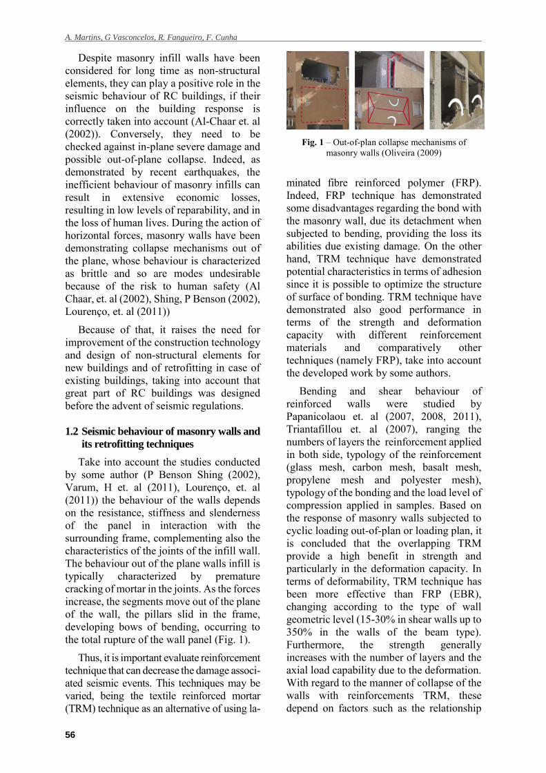
the total rupture of the wall panel (Fig. 1).
Thus, it is important evaluate reinforcement
technique that can decrease the damage associ-
ated seismic events. This techniques may be
varied, being the textile reinforced mortar
(TRM) technique as an alternative of using la-
Fig. 1 – Out-of-plan collapse mechanisms of
masonry walls (Oliveira (2009)
minated fibre reinforced polymer (FRP).
Indeed, FRP technique has demonstrated
some disadvantages regarding the bond with
the masonry wall, due its detachment when
subjected to bending, providing the loss its
abilities due existing damage. On the other
hand, TRM technique have demonstrated
potential characteristics in terms of adhesion
since it is possible to optimize the structure
of surface of bonding. TRM technique have
demonstrated also good performance in
terms of the strength and deformation
capacity with different reinforcement
materials and comparatively other
techniques (namely FRP), take into account
the developed work by some authors.
Bending and shear behaviour of
reinforced walls were studied by
Papanicolaou et. al (2007, 2008, 2011),
Triantafillou et. al (2007), ranging the
numbers of layers the reinforcement applied
in both side, typology of the reinforcement
(glass mesh, carbon mesh, basalt mesh,
propylene mesh and polyester mesh),
typology of the bonding and the load level of
compression applied in samples. Based on
the response of masonry walls subjected to
cyclic loading out-of-plan or loading plan, it
is concluded that the overlapping TRM
provide a high benefit in strength and
particularly in the deformation capacity. In
terms of deformability, TRM technique has
been more effective than FRP (EBR),
changing according to the type of wall
geometric level (15-30% in shear walls up to
350% in the walls of the beam type).
Furthermore, the strength generally
increases with the number of layers and the
axial load capability due to the deformation.
With regard to the manner of collapse of the
walls with reinforcements TRM, these
depend on factors such as the relationship
Caracterização experimental do comportamento de aderência de varões compósitos têxteis
57
between the traction capacity of the
reinforcement and compressive strength of
masonry, bond strength reinforcing wall and
the inside reinforcement.
Rupika (2010) presents a work that
studied the performance the different types
of materials in retrofitting of infill walls.
Steel meshes, glass, carbon and
polypropylene fibre applied on
configuration of meshes were embedded on
the rendering of walls. Steel mesh applied on
plastering masonry walls subjected to
bending tests presented good behaviour in
terms of maximum strength, although the
observed deformation and ductility has not
been so favourable, leading to brittle failure
of the wall due to the low elasticity offered
by strengthening. However, the study was
also made of polymeric material and glass
fibre mesh, showing a low bearing capacity
for the remaining reinforcements, however
they keep after opening cracks up high levels
of deformation. On the other hand, a stiffer
and more homogeneous behaviour is noticed
when TRM is applied. The in-plane stiffness
has proved to be highly dependent on the type
of strengthening mortar whereas the out-of-
plane stiffness is mainly defined by the type
and amount of fibres (Bernat et. al (2013)).
Given this, the potential benefits of the
infills walls reinforcement as way to prevent
serious damage in case of seismic events, go
beyond the mere stability of nonstructural
elements, because it would improve the
behaviour of the whole structure to face
seismic events through of enhancement the
ability the ductility in structure. This
mechanism ensures a high level of
confidence in reinforcing materials and it
allows dissipate energy when subjected to
cyclic loading, this behaviour is observed
during an earthquake (Martins (2013)
Martins et. al (2014)). In that case, through
of the use of textile reinforcement mortar
(TRM), some new structures based on
braiding techniques have been developed in
the last years in the University of Minho
(Fangueiro (2011) Cunha (2012) Martins
(2013)). The idea is to get composites rods
through braided fibrous structures composed
of an internal core of reinforcing fibres, such
us glass or carbon and an external braided
surface made by polyester or other textile
fibres, being after its production combined in
meshes in two perpendicular directions.
Besides the percentage of the reinforcing
materials in the internal core of the braided
structure, it is important to evaluate the most
appropriate spacing of the structures in the
mesh, which reveals to have a great
importance in the improvement of the
flexural behaviour of brick masonry
(Martins (2013), Gómez (2012)). These
materials have several advantages, out of
which it can be remarked the possibility of
designing the composition according to
mechanical requirements and the
implication of low-tech and low-cost
procedures for its production. Moreover, the
shape of the rod can be designed in purpose
of the performance in terms of adherence, in
order to get the best bonding with involved
mortar (Cunha (2012), Cunha, et. al (2013)).
So that, an experimental campaign was
developed in order to analyse the mechanical
behaviour of different external bonding
surfaces when are pulled out inside of mortar
of plastering. Thus, it can possible to
evaluate and optimize its characteristics in
order to select the best configuration of
external surface in order to be applied on
meshes of reinforcement of masonry walls.
Moreover, meshes constituted with these
optimized rods were tested in terms of
adherence through of pull out tests
considering representative samples of
masonry.
2. ADHERENCE TESTS IN INDIVIDU-
AL RODS
2.1 Braided composite rods – BCR
The reinforcement material is designed
by the braided composite rods, BCR and it is
result of a process designed by braiding
simple. This technique for producing
braided fabrics is usually used for the
manufacturing of fibrous reinforcements for
construction applications (Fangueiro
(2011)). It has been used for two centuries
and is being increasingly used for technical
applications. This technology consists on a
A. Martins, G Vasconcelos, R. Fangueiro, F. Cunha
58
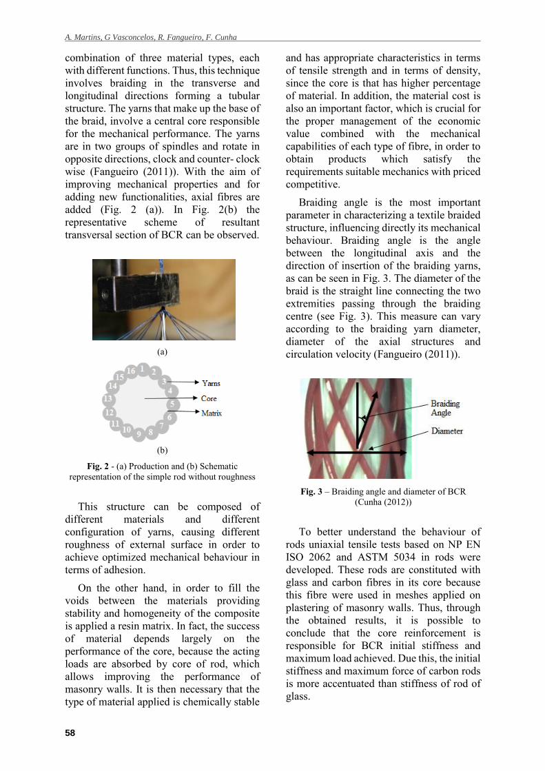
combination of three material types, each
with different functions. Thus, this technique
involves braiding in the transverse and
longitudinal directions forming a tubular
structure. The yarns that make up the base of
the braid, involve a central core responsible
for the mechanical performance. The yarns
are in two groups of spindles and rotate in
opposite directions, clock and counter- clock
wise (Fangueiro (2011)). With the aim of
improving mechanical properties and for
adding new functionalities, axial fibres are
added (Fig. 2 (a)). In Fig. 2(b) the
representative scheme of resultant
transversal section of BCR can be observed.
(a)
(b)
Fig. 2 - (a) Production and (b) Schematic
representation of the simple rod without roughness
This structure can be composed of
different materials and different
configuration of yarns, causing different
roughness of external surface in order to
achieve optimized mechanical behaviour in
terms of adhesion.
On the other hand, in order to fill the
voids between the materials providing
stability and homogeneity of the composite
is applied a resin matrix. In fact, the success
of material depends largely on the
performance of the core, because the acting
loads are absorbed by core of rod, which
allows improving the performance of
masonry walls. It is then necessary that the
type of material applied is chemically stable
and has appropriate characteristics in terms
of tensile strength and in terms of density,
since the core is that has higher percentage
of material. In addition, the material cost is
also an important factor, which is crucial for
the proper management of the economic
value combined with the mechanical
capabilities of each type of fibre, in order to
obtain products which satisfy the
requirements suitable mechanics with priced
competitive.
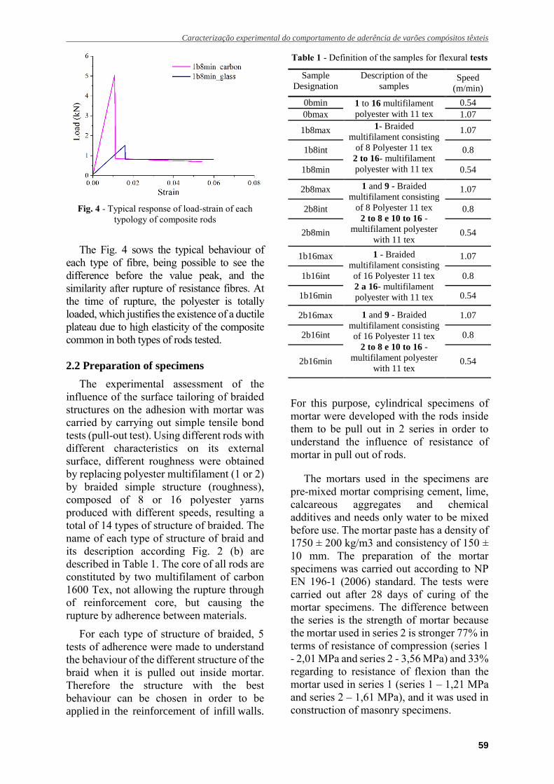
Braiding angle is the most important
parameter in characterizing a textile braided
structure, influencing directly its mechanical
behaviour. Braiding angle is the angle
between the longitudinal axis and the
direction of insertion of the braiding yarns,
as can be seen in Fig. 3. The diameter of the
braid is the straight line connecting the two
extremities passing through the braiding
centre (see Fig. 3). This measure can vary
according to the braiding yarn diameter,
diameter of the axial structures and
circulation velocity (Fangueiro (2011)).
Fig. 3 – Braiding angle and diameter of BCR
(Cunha (2012))
To better understand the behaviour of
rods uniaxial tensile tests based on NP EN
ISO 2062 and ASTM 5034 in rods were
developed. These rods are constituted with
glass and carbon fibres in its core because
this fibre were used in meshes applied on
plastering of masonry walls. Thus, through
the obtained results, it is possible to
conclude that the core reinforcement is
responsible for BCR initial stiffness and
maximum load achieved. Due this, the initial
stiffness and maximum force of carbon rods
is more accentuated than stiffness of rod of
glass.
Caracterização experimental do comportamento de aderência de varões compósitos têxteis
59
Fig. 4 - Typical response of load-strain of each
typology of composite rods
The Fig. 4 sows the typical behaviour of
each type of fibre, being possible to see the
difference before the value peak, and the
similarity after rupture of resistance fibres. At
the time of rupture, the polyester is totally
loaded, which justifies the existence of a ductile
plateau due to high elasticity of the composite
common in both types of rods tested.
2.2 Preparation of specimens
The experimental assessment of the
influence of the surface tailoring of braided
structures on the adhesion with mortar was
carried by carrying out simple tensile bond
tests (pull-out test). Using different rods with
different characteristics on its external
surface, different roughness were obtained
by replacing polyester multifilament (1 or 2)
by braided simple structure (roughness),
composed of 8 or 16 polyester yarns
produced with different speeds, resulting a
total of 14 types of structure of braided. The
name of each type of structure of braid and
its description according Fig. 2 (b) are
described in Table 1. The core of all rods are
constituted by two multifilament of carbon
1600 Tex, not allowing the rupture through
of reinforcement core, but causing the
rupture by adherence between materials.
For each type of structure of braided, 5
tests of adherence were made to understand
the behaviour of the different structure of the
braid when it is pulled out inside mortar.
Therefore the structure with the best
behaviour can be chosen in order to be
applied in the reinforcement of infill walls.
Table 1 - Definition of the samples for flexural tests
Sample
Designation
Description of the
samples
Speed
(m/min)
0bmin 1 to 16 multifilament
polyester with 11 tex
0.54
0bmax 1.07
1b8max 1- Braided
multifilament consisting
of 8 Polyester 11 tex
2 to 16- multifilament
polyester with 11 tex
1.07
1b8int 0.8
1b8min 0.54
2b8max 1 and 9 - Braided
multifilament consisting
of 8 Polyester 11 tex
2 to 8 e 10 to 16 -
multifilament polyester
with 11 tex
1.07
2b8int 0.8
2b8min 0.54
1b16max 1 - Braided
multifilament consisting
of 16 Polyester 11 tex
2 a 16- multifilament
polyester with 11 tex
1.07
1b16int 0.8
1b16min 0.54
2b16max 1 and 9 - Braided
multifilament consisting
of 16 Polyester 11 tex
2 to 8 e 10 to 16 -
multifilament polyester
with 11 tex
1.07
2b16int 0.8
2b16min 0.54
For this purpose, cylindrical specimens of
mortar were developed with the rods inside
them to be pull out in 2 series in order to
understand the influence of resistance of
mortar in pull out of rods.
The mortars used in the specimens are
pre-mixed mortar comprising cement, lime,
calcareous aggregates and chemical
additives and needs only water to be mixed
before use. The mortar paste has a density of
1750 ± 200 kg/m3 and consistency of 150 ±
10 mm. The preparation of the mortar
specimens was carried out according to NP
EN 196-1 (2006) standard. The tests were
carried out after 28 days of curing of the
mortar specimens. The difference between
the series is the strength of mortar because
the mortar used in series 2 is stronger 77% in
terms of resistance of compression (series 1
- 2,01 MPa and series 2 - 3,56 MPa) and 33%
regarding to resistance of flexion than the
mortar used in series 1 (series 1 – 1,21 MPa
and series 2 – 1,61 MPa), and it was used in
construction of masonry specimens.
A. Martins, G Vasconcelos, R. Fangueiro, F. Cunha
60
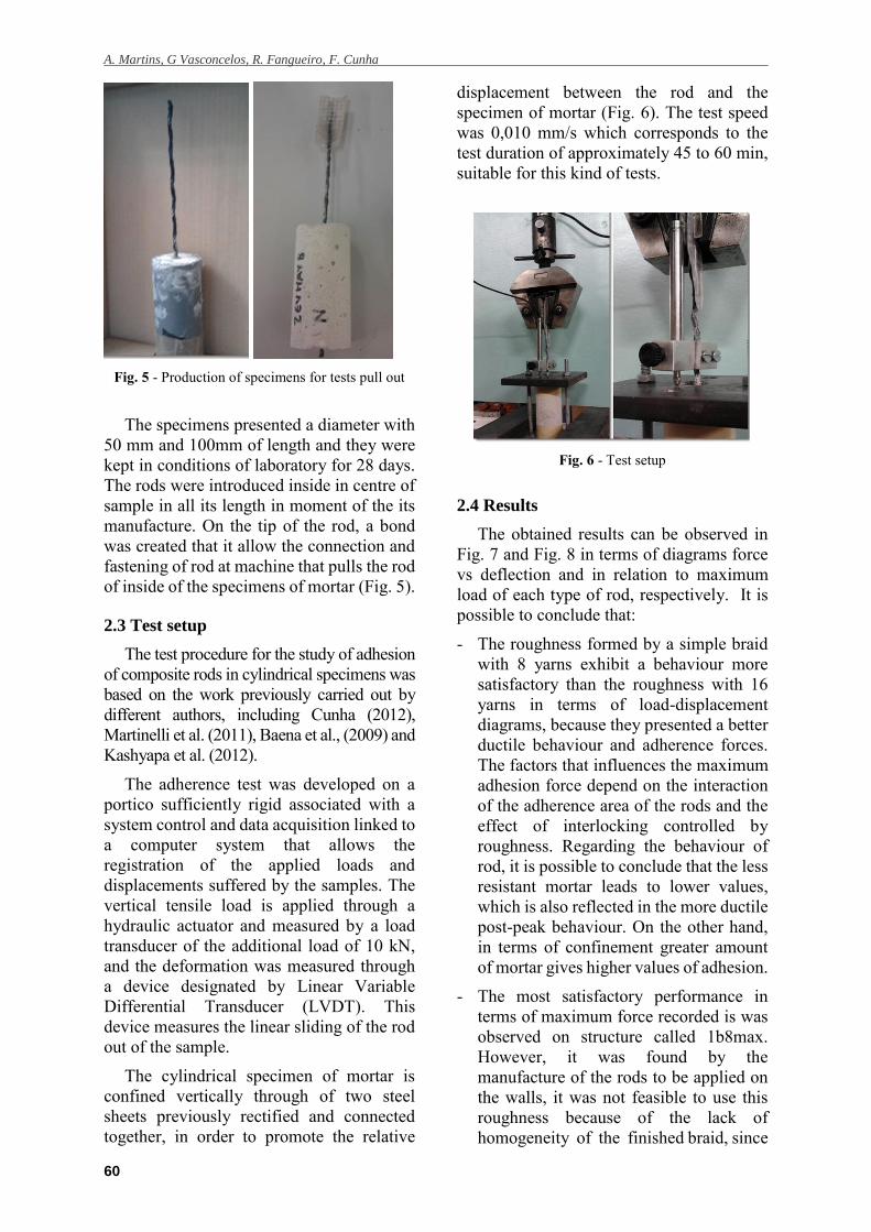
Fig. 5 - Production of specimens for tests pull out
The specimens presented a diameter with
50 mm and 100mm of length and they were
kept in conditions of laboratory for 28 days.
The rods were introduced inside in centre of
sample in all its length in moment of the its
manufacture. On the tip of the rod, a bond
was created that it allow the connection and
fastening of rod at machine that pulls the rod
of inside of the specimens of mortar (Fig. 5).
2.3 Test setup
The test procedure for the study of adhesion
of composite rods in cylindrical specimens was
based on the work previously carried out by
different authors, including Cunha (2012),
Martinelli et al. (2011), Baena et al., (2009) and
Kashyapa et al. (2012).
The adherence test was developed on a
portico sufficiently rigid associated with a
system control and data acquisition linked to
a computer system that allows the
registration of the applied loads and
displacements suffered by the samples. The
vertical tensile load is applied through a
hydraulic actuator and measured by a load
transducer of the additional load of 10 kN,
and the deformation was measured through
a device designated by Linear Variable
Differential Transducer (LVDT). This
device measures the linear sliding of the rod
out of the sample.
The cylindrical specimen of mortar is
confined vertically through of two steel
sheets previously rectified and connected
together, in order to promote the relative
displacement between the rod and the
specimen of mortar (Fig. 6). The test speed
was 0,010 mm/s which corresponds to the
test duration of approximately 45 to 60 min,
suitable for this kind of tests.
Fig. 6 - Test setup
2.4 Results
The obtained results can be observed in
Fig. 7 and Fig. 8 in terms of diagrams force
vs deflection and in relation to maximum
load of each type of rod, respectively. It is
possible to conclude that:
- The roughness formed by a simple braid
with 8 yarns exhibit a behaviour more
satisfactory than the roughness with 16
yarns in terms of load-displacement
diagrams, because they presented a better
ductile behaviour and adherence forces.
The factors that influences the maximum
adhesion force depend on the interaction
of the adherence area of the rods and the
effect of interlocking controlled by
roughness. Regarding the behaviour of
rod, it is possible to conclude that the less
resistant mortar leads to lower values,
which is also reflected in the more ductile
post-peak behaviour. On the other hand,
in terms of confinement greater amount
of mortar gives higher values of adhesion.
- The most satisfactory performance in
terms of maximum force recorded is was
observed on structure called 1b8max.
However, it was found by the
manufacture of the rods to be applied on
the walls, it was not feasible to use this
roughness because of the lack of
homogeneity of the finished braid, since

Caracterização experimental do comportamento de aderência de varões compósitos têxteis
61
Fig. 7 - Maximum load for each type of rod
(a)
(b)
Fig. 8 - Obtained results in (a) series 1 and (b) series 2
it was necessary to increase the amount of
material in the core. It can also be concluded
that the manufacture of the rods from the
braiding technique with existing conditions
may depend on the diameter of the
reinforcement to be included in the core.
Therefore, the alternative braided structure
selected for rod was 1b8min, consisting of
15 multifilament polyester 11 Tex and 1
element of braided simple structure
consisting of 8 braided polyester yarn with
minimum speed of the production equipment
(0.54 m/min). Therefore, the braided protect
the core totally because the minimum speed
allows better involvement of the core. Thus,
the selected BCR rod has a helical ledge
which increases the bonding to the mortar
through the engaging its shape.
3 AHERENCE TESTS IN REPRESEN-
TATIVE MESHES OF REINFORCE-
MENT
3.1 Meshes of reinforcement
Representative meshes were developed
with selected braid structure, in order to
understand the behaviour of a set of rods
when are pulled out inside plastering of
mortar on masonry samples. The rods are
constituted by two multifilament of carbon
1600 Tex as in tests in cylindrical samples,
and the selected braid structure was 1b8min,
taking into account the production of
reinforcement to be applied on masonry
walls. Besides this braid structure, the
original configuration without roughness
(0bmin) was also considered in order to
analyse the influence of roughness in
adherence to mortar.
The manufacture of the meshes is made by
interlacing the rods in two directions. The
configuration of the connections of rods leads
to some roughness of the mesh, which can
results in an additional imbrication (Fig. 9).
Beyond the study of the meshes constituted
by braided composite rods, two commercial
solutions with similar mechanical and physical
characteristics were tested in order to get the
viability of produced meshes. These meshes
Fig. 9 – Details of mesh
A. Martins, G Vasconcelos, R. Fangueiro, F. Cunha
62
are different in terms of type of fibers,
being the Comm_carb constituted by
carbon fiber in main direction and
Comm_glass constituted by glass fibers.
The Comm_carb is unidirectional, taking
into account that carbon fibers are oriented
in the direction where bending develops,
whose density is 200 g/m with spacing of
approximately 25mm the main direction.
Based on the technical information, the
mesh has a flexural strength of 93.6 kN/m
for an extension at maximum stress of 1.75
%. The commercial mesh of glass fibers
(Comm_glass) consists of resistant glass
fibers in both directions. Once
bidirectional, the mesh density is 225g/m2
with spacing between the fibers of 25mm.
From the technical information, it is seen
that the flexural strength is 45 kN/m with
associated extension at break less than or
equal to 3%.
Because of theses meshes present the
spacing of 25mm, manufactured meshes
were developed with same spacing in order
to minimize difference between them.
3.2 Preparation of specimens
The construction of representative
masonry specimens was made by an
experienced mason in order to reproduce
similar workmanship used in current
structures. The samples were kept under
relatively stable conditions of temperature
and humidity inside the laboratory (Fig. 10).
This was made by applying a thin layer of
mortar, with subsequent placement of the
reinforcing mesh embedded in a new layer
of rendering mortar, giving a total thickness
of about 20mm. The mortar used in this tests
was used in series 2 of individual rods tests
and in construction of masonry walls.
The dimension of inserted mesh in
plastering was (length x width) 200 mm x
100 mm, presenting the same free area on
sample. On the tip of the each mesh applied
on sample, a bond was created that it allow
the connection and fastening of mesh at
machine, as was created in individual rods.
For each typology of mesh, 5 tests were
considered taking into account the viability
of obtained results.
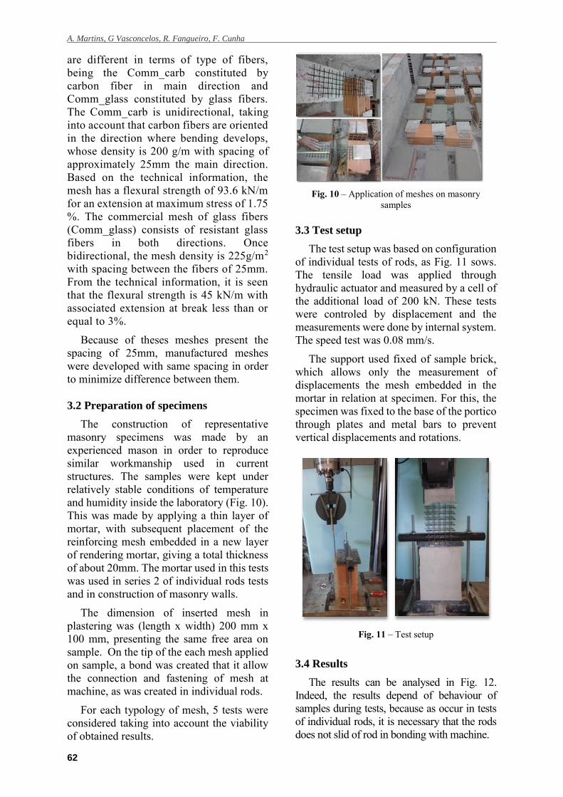
Fig. 10 – Application of meshes on masonry
samples
3.3 Test setup
The test setup was based on configuration
of individual tests of rods, as Fig. 11 sows.
The tensile load was applied through
hydraulic actuator and measured by a cell of
the additional load of 200 kN. These tests
were controled by displacement and the
measurements were done by internal system.
The speed test was 0.08 mm/s.
The support used fixed of sample brick,
which allows only the measurement of
displacements the mesh embedded in the
mortar in relation at specimen. For this, the
specimen was fixed to the base of the portico
through plates and metal bars to prevent
vertical displacements and rotations.
Fig. 11 – Test setup
3.4 Results
The results can be analysed in Fig. 12.
Indeed, the results depend of behaviour of
samples during tests, because as occur in tests
of individual rods, it is necessary that the rods
does not slid of rod in bonding with machine.
Caracterização experimental do comportamento de aderência de varões compósitos têxteis
63
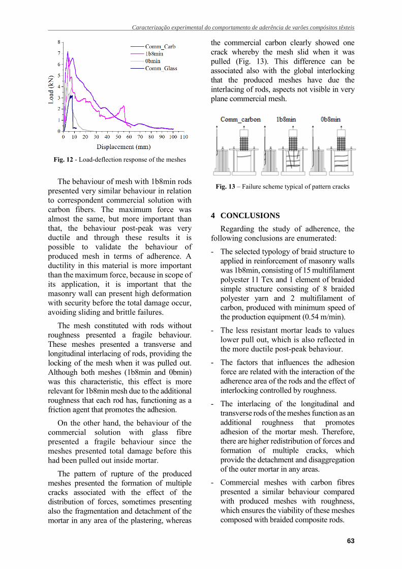
Fig. 12 - Load-deflection response of the meshes
The behaviour of mesh with 1b8min rods
presented very similar behaviour in relation
to correspondent commercial solution with
carbon fibers. The maximum force was
almost the same, but more important than
that, the behaviour post-peak was very
ductile and through these results it is
possible to validate the behaviour of
produced mesh in terms of adherence. A
ductility in this material is more important
than the maximum force, because in scope of
its application, it is important that the
masonry wall can present high deformation
with security before the total damage occur,
avoiding sliding and brittle failures.
The mesh constituted with rods without
roughness presented a fragile behaviour.
These meshes presented a transverse and
longitudinal interlacing of rods, providing the
locking of the mesh when it was pulled out.
Although both meshes (1b8min and 0bmin)
was this characteristic, this effect is more
relevant for 1b8min mesh due to the additional
roughness that each rod has, functioning as a
friction agent that promotes the adhesion.
On the other hand, the behaviour of the
commercial solution with glass fibre
presented a fragile behaviour since the
meshes presented total damage before this
had been pulled out inside mortar.
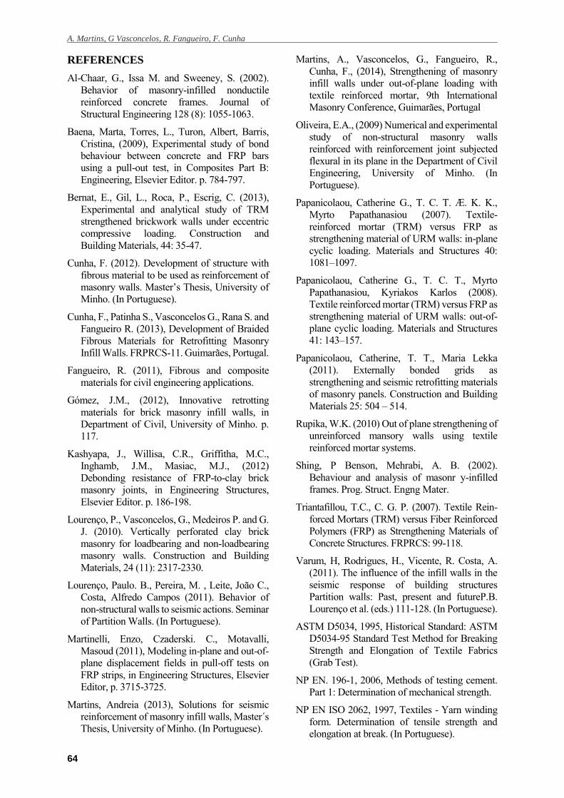
The pattern of rupture of the produced
meshes presented the formation of multiple
cracks associated with the effect of the
distribution of forces, sometimes presenting
also the fragmentation and detachment of the
mortar in any area of the plastering, whereas
the commercial carbon clearly showed one
crack whereby the mesh slid when it was
pulled (Fig. 13). This difference can be
associated also with the global interlocking
that the produced meshes have due the
interlacing of rods, aspects not visible in very
plane commercial mesh.
Fig. 13 – Failure scheme typical of pattern cracks
4 CONCLUSIONS
Regarding the study of adherence, the
following conclusions are enumerated:
- The selected typology of braid structure to
applied in reinforcement of masonry walls
was 1b8min, consisting of 15 multifilament
polyester 11 Tex and 1 element of braided
simple structure consisting of 8 braided
polyester yarn and 2 multifilament of
carbon, produced with minimum speed of
the production equipment (0.54 m/min).
- The less resistant mortar leads to values
lower pull out, which is also reflected in
the more ductile post-peak behaviour.
- The factors that influences the adhesion
force are related with the interaction of the
adherence area of the rods and the effect of
interlocking controlled by roughness.
- The interlacing of the longitudinal and
transverse rods of the meshes function as an
additional roughness that promotes
adhesion of the mortar mesh. Therefore,
there are higher redistribution of forces and
formation of multiple cracks, which
provide the detachment and disaggregation
of the outer mortar in any areas.
- Commercial meshes with carbon fibres
presented a similar behaviour compared
with produced meshes with roughness,
which ensures the viability of these meshes
composed with braided composite rods.
A. Martins, G Vasconcelos, R. Fangueiro, F. Cunha
64
REFERENCES
Al-Chaar, G., Issa M. and Sweeney, S. (2002).
Behavior of masonry-infilled nonductile
reinforced concrete frames. Journal of
Structural Engineering 128 (8): 1055-1063.
Baena, Marta, Torres, L., Turon, Albert, Barris,
Cristina, (2009), Experimental study of bond
behaviour between concrete and FRP bars
using a pull-out test, in Composites Part B:
Engineering, Elsevier Editor. p. 784-797.
Bernat, E., Gil, L., Roca, P., Escrig, C. (2013),
Experimental and analytical study of TRM
strengthened brickwork walls under eccentric
compressive loading. Construction and
Building Materials, 44: 35-47.
Cunha, F. (2012). Development of structure with
fibrous material to be used as reinforcement of
masonry walls. Master’s Thesis, University of
Minho. (In Portuguese).
Cunha, F., Patinha S., Vasconcelos G., Rana S. and
Fangueiro R. (2013), Development of Braided
Fibrous Materials for Retrofitting Masonry
Infill Walls. FRPRCS-11. Guimarães, Portugal.
Fangueiro, R. (2011), Fibrous and composite
materials for civil engineering applications.
Gómez, J.M., (2012), Innovative retrotting
materials for brick masonry infill walls, in
Department of Civil, University of Minho. p.
117.
Kashyapa, J., Willisa, C.R., Griffitha, M.C.,
Inghamb, J.M., Masiac, M.J., (2012)
Debonding resistance of FRP-to-clay brick
masonry joints, in Engineering Structures,
Elsevier Editor. p. 186-198.
Lourenço, P., Vasconcelos, G., Medeiros P. and G.
J. (2010). Vertically perforated clay brick
masonry for loadbearing and non-loadbearing
masonry walls. Construction and Building
Materials, 24 (11): 2317-2330.
Lourenço, Paulo. B., Pereira, M. , Leite, João C.,
Costa, Alfredo Campos (2011). Behavior of
non-structural walls to seismic actions. Seminar
of Partition Walls. (In Portuguese).
Martinelli, Enzo, Czaderski. C., Motavalli,
Masoud (2011), Modeling in-plane and out-of-
plane displacement fields in pull-off tests on
FRP strips, in Engineering Structures, Elsevier
Editor, p. 3715-3725.
Martins, Andreia (2013), Solutions for seismic
reinforcement of masonry infill walls, Master´s
Thesis, University of Minho. (In Portuguese).
Martins, A., Vasconcelos, G., Fangueiro, R.,
Cunha, F., (2014), Strengthening of masonry
infill walls under out-of-plane loading with
textile reinforced mortar, 9th International
Masonry Conference, Guimarães, Portugal
Oliveira, E.A., (2009) Numerical and experimental
study of non-structural masonry walls
reinforced with reinforcement joint subjected
flexural in its plane in the Department of Civil
Engineering, University of Minho. (In
Portuguese).
Papanicolaou, Catherine G., T. C. T. Æ. K. K.,
Myrto Papathanasiou (2007). Textile-
reinforced mortar (TRM) versus FRP as
strengthening material of URM walls: in-plane
cyclic loading. Materials and Structures 40:
1081–1097.
Papanicolaou, Catherine G., T. C. T., Myrto
Papathanasiou, Kyriakos Karlos (2008).
Textile reinforced mortar (TRM) versus FRP as
strengthening material of URM walls: out-of-
plane cyclic loading. Materials and Structures
41: 143–157.
Papanicolaou, Catherine, T. T., Maria Lekka
(2011). Externally bonded grids as
strengthening and seismic retrofitting materials
of masonry panels. Construction and Building
Materials 25: 504 – 514.
Rupika, W.K. (2010) Out of plane strengthening of
unreinforced mansory walls using textile
reinforced mortar systems.
Shing, P Benson, Mehrabi, A. B. (2002).
Behaviour and analysis of masonr y-infilled
frames. Prog. Struct. Engng Mater.
Triantafillou, T.C., C. G. P. (2007). Textile Rein-
forced Mortars (TRM) versus Fiber Reinforced
Polymers (FRP) as Strengthening Materials of
Concrete Structures. FRPRCS: 99-118.
Varum, H, Rodrigues, H., Vicente, R. Costa, A.
(2011). The influence of the infill walls in the
seismic response of building structures
Partition walls: Past, present and futureP.B.
Lourenço et al. (eds.) 111-128. (In Portuguese).
ASTM D5034, 1995, Historical Standard: ASTM
D5034-95 Standard Test Method for Breaking
Strength and Elongation of Textile Fabrics
(Grab Test).
NP EN. 196-1, 2006, Methods of testing cement.
Part 1: Determination of mechanical strength.
NP EN ISO 2062, 1997, Textiles - Yarn winding
form. Determination of tensile strength and
elongation at break. (In Portuguese).