Embed Size (px)
Citation preview

10/08/07 1
DAKE / JOHNSON VERTICAL BAND SAW
Model V–24 VH-24 INSTRUCTION MANUAL After 6/2007 or serial number 1032561
VH-24 Pictured
Need band saw blades? Call Dake DAKE (Division of JSJ) 724 Robbins Road Grand Haven, Michigan 49417 616.842.7110 Phone 800-937-3253 616.842.0859 Fax 800-846-3253 Web: www.dakecorp.com
MODEL: V-24_______________________ SERIAL NUMBER: __________________ DATE PURCHASED: ________________

10/08/07 2
WARNING!
This machine must be wired by a qualified electrician. This machine is designed to be wired for the specified voltage with a tolerance of +/- 10%. If your voltage is outside this 10% it will require a transformer to obtain the correct voltage. Failure to do so may affect warranty, if damage occurs from improper wiring or electrical supply.
FOREWORD These instructions cover the installation and operation of vertical band saw. We recommend that these instructions be retained by the department or individual responsible for the machine and kept in a readily accessible location for reference purposes.
10/08/07 3
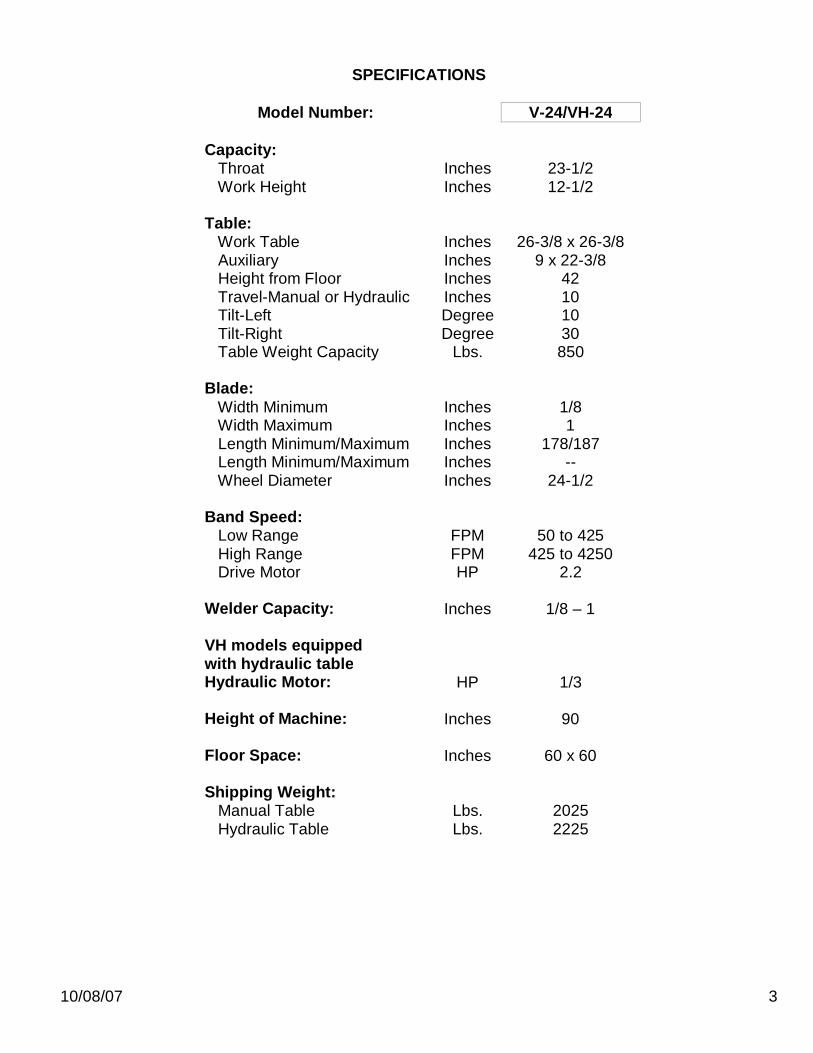
SPECIFICATIONS
Model Number: V-24/VH-24
Capacity: Throat Inches 23-1/2 Work Height Inches 12-1/2
Table: Work Table Inches 26-3/8 x 26-3/8 Auxiliary Inches 9 x 22-3/8 Height from Floor Inches 42 Travel-Manual or Hydraulic Inches 10 Tilt-Left Degree 10 Tilt-Right Degree 30 Table Weight Capacity Lbs. 850 Blade: Width Minimum Inches 1/8 Width Maximum Inches 1 Length Minimum/Maximum Inches 178/187 Length Minimum/Maximum Inches -- Wheel Diameter Inches 24-1/2 Band Speed: Low Range FPM 50 to 425 High Range FPM 425 to 4250 Drive Motor HP 2.2 Welder Capacity: Inches 1/8 – 1 VH models equipped with hydraulic table Hydraulic Motor: HP 1/3 Height of Machine: Inches 90 Floor Space: Inches 60 x 60 Shipping Weight: Manual Table Lbs. 2025 Hydraulic Table Lbs. 2225
10/08/07 4
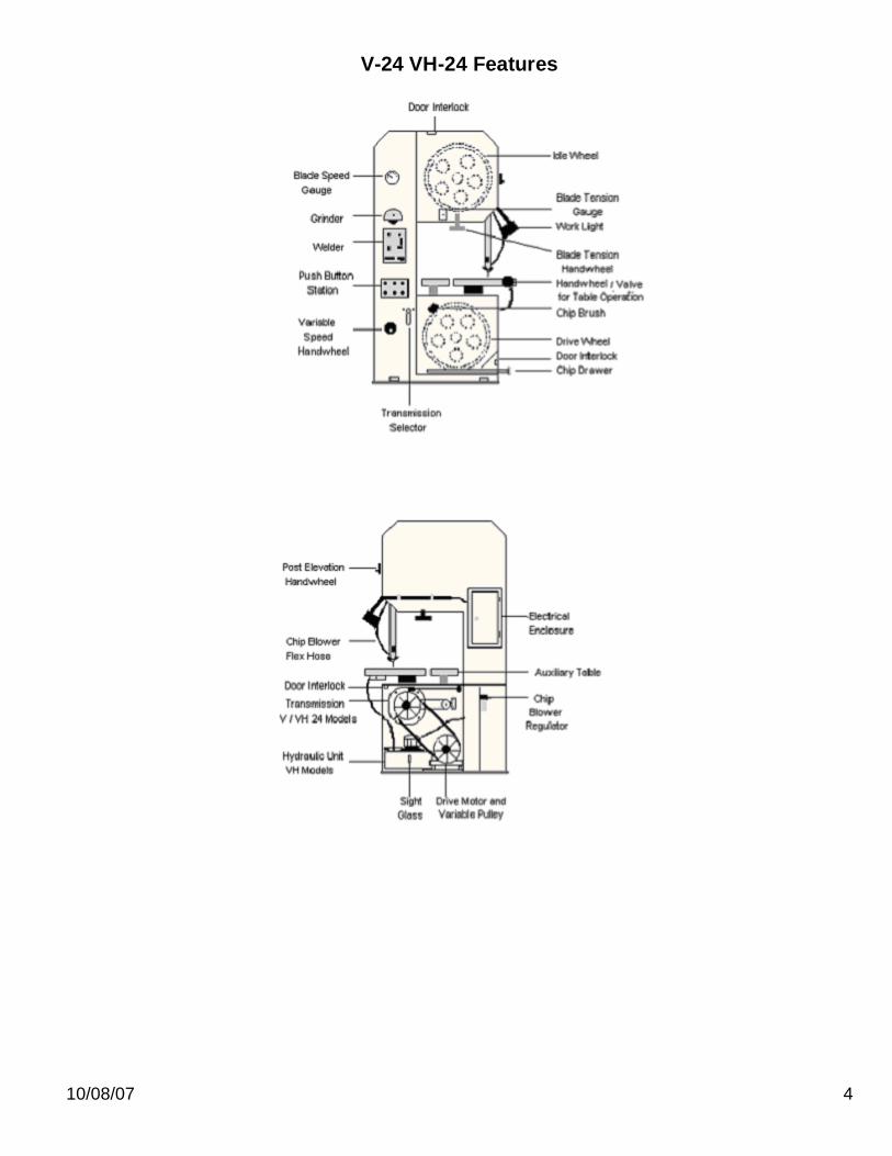
V-24 VH-24 Features
10/08/07 5
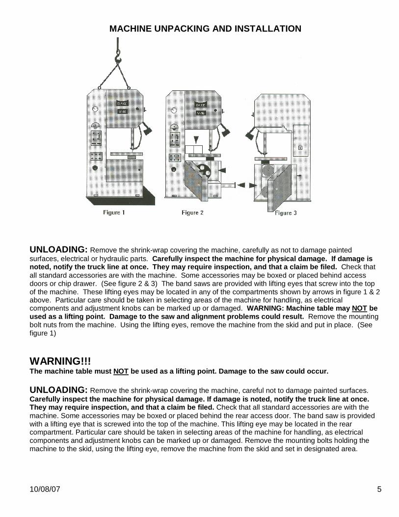
MACHINE UNPACKING AND INSTALLATION
UNLOADING: Remove the shrink-wrap covering the machine, carefully as not to damage painted surfaces, electrical or hydraulic parts. Carefully inspect the machine for physical damage. If damage is noted, notify the truck line at once. They may require inspection, and that a claim be filed. Check that all standard accessories are with the machine. Some accessories may be boxed or placed behind access doors or chip drawer. (See figure 2 & 3) The band saws are provided with lifting eyes that screw into the top of the machine. These lifting eyes may be located in any of the compartments shown by arrows in figure 1 & 2 above. Particular care should be taken in selecting areas of the machine for handling, as electrical components and adjustment knobs can be marked up or damaged. WARNING: Machine table may NOT be used as a lifting point. Damage to the saw and alignment problems could result. Remove the mounting bolt nuts from the machine. Using the lifting eyes, remove the machine from the skid and put in place. (See figure 1) WARNING!!! The machine table must NOT be used as a lifting point. Damage to the saw could occur. UNLOADING: Remove the shrink-wrap covering the machine, careful not to damage painted surfaces. Carefully inspect the machine for physical damage. If damage is noted, notify the truck line at once. They may require inspection, and that a claim be filed. Check that all standard accessories are with the machine. Some accessories may be boxed or placed behind the rear access door. The band saw is provided with a lifting eye that is screwed into the top of the machine. This lifting eye may be located in the rear compartment. Particular care should be taken in selecting areas of the machine for handling, as electrical components and adjustment knobs can be marked up or damaged. Remove the mounting bolts holding the machine to the skid, using the lifting eye, remove the machine from the skid and set in designated area.
10/08/07 6
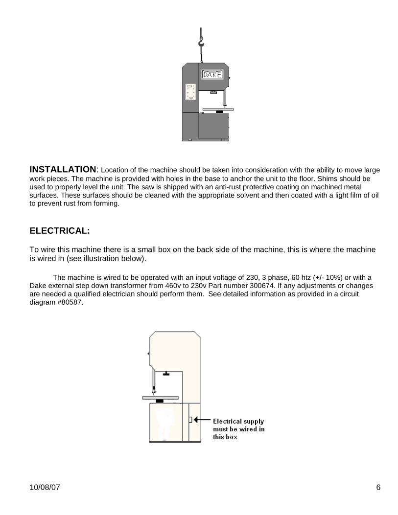
INSTALLATION: Location of the machine should be taken into consideration with the ability to move large work pieces. The machine is provided with holes in the base to anchor the unit to the floor. Shims should be used to properly level the unit. The saw is shipped with an anti-rust protective coating on machined metal surfaces. These surfaces should be cleaned with the appropriate solvent and then coated with a light film of oil to prevent rust from forming. ELECTRICAL: To wire this machine there is a small box on the back side of the machine, this is where the machine is wired in (see illustration below).
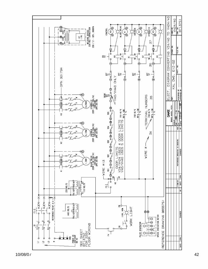
The machine is wired to be operated with an input voltage of 230, 3 phase, 60 htz (+/- 10%) or with a Dake external step down transformer from 460v to 230v Part number 300674. If any adjustments or changes are needed a qualified electrician should perform them. See detailed information as provided in a circuit diagram #80587.

10/08/07 7
warning!!! Power must be locked out before opening any electrical panel.
WARNING!
This machine must be wired by a qualified electrician. This machine is designed to be wired for the specified voltage with a tolerance of +/- 10%. If your voltage is outside this 10% it will require a transformer to obtain the correct voltage. Failure to do so may affect warranty, if damage occurs from improper wiring or electrical supply. Prior to performing any cutting with the machine, it is recommended that the personal become familiar with the various controls and accessories. PRECAUTIONS No loose clothing. Eye protection must be worn. All guards must be in position. Table load capacity should be noted and not exceeded. Extra supports may be required for large material or components. Irregular shapes and small objects should be secured by means of a clamp or suitable fixture. Machine and surrounding should be kept free of tools, scrap and foreign objects. Machine should be locked out before making any adjustments. Gloves must be used when uncoiling, coiling and installing band saw blades. Store band saw blades in an area near the machine. This will allow operating personal to use the proper
blade for each operation. Machine is furnished with electrical door interlocks. These interlocks should periodically be checked for
proper operation. BLADE INSTALLATION WARNING!!! Gloves must be worn when changing the blade. WARNING!!! Electrical supply must be locked out when changing the blade. Blade selection is based on the many factors and complexity of the work to be cut.
10/08/07 8
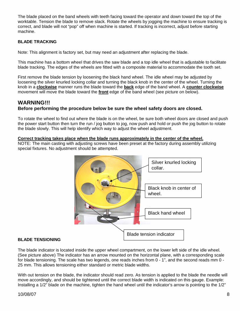
The blade placed on the band wheels with teeth facing toward the operator and down toward the top of the worktable. Tension the blade to remove slack. Rotate the wheels by jogging the machine to ensure tracking is correct, and blade will not “pop” off when machine is started. If tracking is incorrect, adjust before starting machine. BLADE TRACKING Note: This alignment is factory set, but may need an adjustment after replacing the blade. This machine has a bottom wheel that drives the saw blade and a top idle wheel that is adjustable to facilitate blade tracking. The edges of the wheels are fitted with a composite material to accommodate the tooth set. First remove the blade tension by loosening the black hand wheel. The idle wheel may be adjusted by loosening the silver knurled locking collar and turning the black knob in the center of the wheel. Turning the knob in a clockwise manner runs the blade toward the back edge of the band wheel. A counter clockwise movement will move the blade toward the front edge of the band wheel (see picture on below). WARNING!!! Before performing the procedure below be sure the wheel safety doors are closed. To rotate the wheel to find out where the blade is on the wheel, be sure both wheel doors are closed and push the power start button then turn the run / jog button to jog, now push and hold or push the jog button to rotate the blade slowly. This will help identify which way to adjust the wheel adjustment. Correct tracking takes place when the blade runs approximately in the center of the wheel. NOTE: The main casting with adjusting screws have been preset at the factory during assembly utilizing special fixtures. No adjustment should be attempted.
BLADE TENSIONING The blade indicator is located inside the upper wheel compartment, on the lower left side of the idle wheel. (See picture above) The indicator has an arrow mounted on the horizontal plane, with a corresponding scale for blade tensioning. The scale has two legends, one reads inches from 0 - 1”, and the second reads mm 0 - 25 mm. This allows tensioning either standard or metric blade widths. With out tension on the blade, the indicator should read zero. As tension is applied to the blade the needle will move accordingly, and should be tightened until the correct blade width is indicated on this gauge. Example: Installing a 1/2” blade on the machine, tighten the hand wheel until the indicator’s arrow is pointing to the 1/2”
Silver knurled locking collar.
Black knob in center of wheel.
Blade tension indicator
Black hand wheel
10/08/07 9
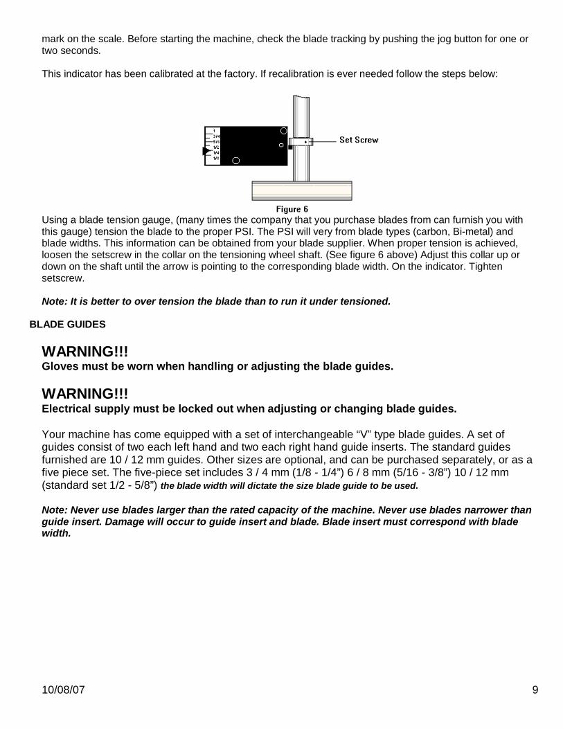
mark on the scale. Before starting the machine, check the blade tracking by pushing the jog button for one or two seconds. This indicator has been calibrated at the factory. If recalibration is ever needed follow the steps below:
Using a blade tension gauge, (many times the company that you purchase blades from can furnish you with this gauge) tension the blade to the proper PSI. The PSI will very from blade types (carbon, Bi-metal) and blade widths. This information can be obtained from your blade supplier. When proper tension is achieved, loosen the setscrew in the collar on the tensioning wheel shaft. (See figure 6 above) Adjust this collar up or down on the shaft until the arrow is pointing to the corresponding blade width. On the indicator. Tighten setscrew. Note: It is better to over tension the blade than to run it under tensioned.
BLADE GUIDES WARNING!!! Gloves must be worn when handling or adjusting the blade guides. WARNING!!! Electrical supply must be locked out when adjusting or changing blade guides. Your machine has come equipped with a set of interchangeable “V” type blade guides. A set of guides consist of two each left hand and two each right hand guide inserts. The standard guides furnished are 10 / 12 mm guides. Other sizes are optional, and can be purchased separately, or as a five piece set. The five-piece set includes 3 / 4 mm (1/8 - 1/4”) 6 / 8 mm (5/16 - 3/8”) 10 / 12 mm (standard set 1/2 - 5/8”) the blade width will dictate the size blade guide to be used. Note: Never use blades larger than the rated capacity of the machine. Never use blades narrower than guide insert. Damage will occur to guide insert and blade. Blade insert must correspond with blade width.
10/08/07 10
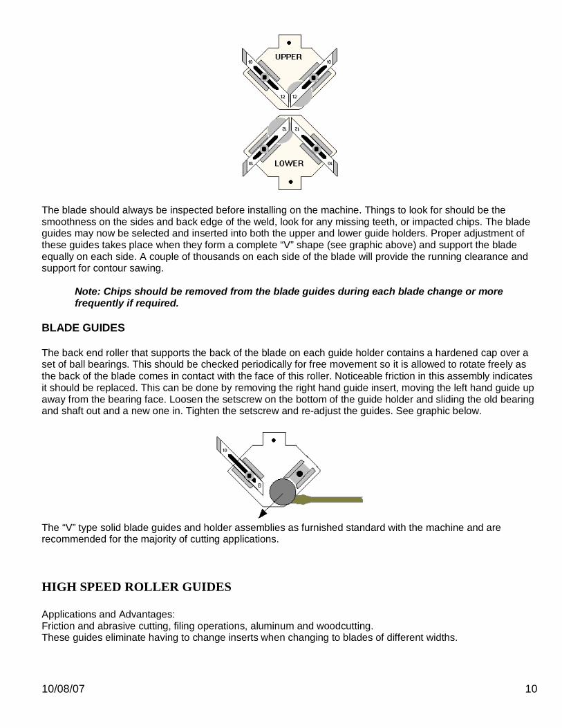
The blade should always be inspected before installing on the machine. Things to look for should be the smoothness on the sides and back edge of the weld, look for any missing teeth, or impacted chips. The blade guides may now be selected and inserted into both the upper and lower guide holders. Proper adjustment of these guides takes place when they form a complete “V” shape (see graphic above) and support the blade equally on each side. A couple of thousands on each side of the blade will provide the running clearance and support for contour sawing.
Note: Chips should be removed from the blade guides during each blade change or more frequently if required.
BLADE GUIDES The back end roller that supports the back of the blade on each guide holder contains a hardened cap over a set of ball bearings. This should be checked periodically for free movement so it is allowed to rotate freely as the back of the blade comes in contact with the face of this roller. Noticeable friction in this assembly indicates it should be replaced. This can be done by removing the right hand guide insert, moving the left hand guide up away from the bearing face. Loosen the setscrew on the bottom of the guide holder and sliding the old bearing and shaft out and a new one in. Tighten the setscrew and re-adjust the guides. See graphic below.
The “V” type solid blade guides and holder assemblies as furnished standard with the machine and are recommended for the majority of cutting applications.
HIGH SPEED ROLLER GUIDES Applications and Advantages: Friction and abrasive cutting, filing operations, aluminum and woodcutting. These guides eliminate having to change inserts when changing to blades of different widths.
10/08/07 11
Requirements for Installation:
These roller guides must be installed using a new 1/2” blade width band for proper alignment. The 1/2” band should be tracked within the approximate center line of the band wheels.
Note: Be certain band wheels are clean are free of any foreign material build up before proceeding.
Tools / Hardware Required:
Drill - 7/16” Drill and tap for ¼” 20 set screw ¼” 20 set screw 1/4 - 3/8” long
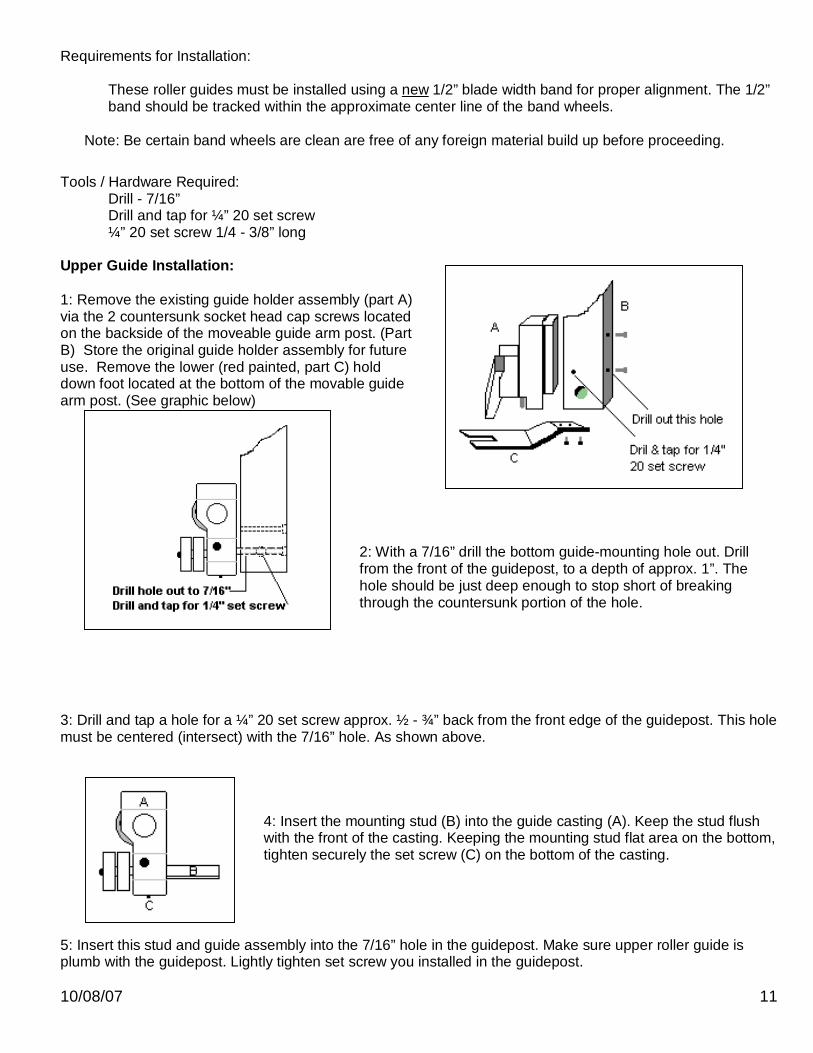
Upper Guide Installation: 1: Remove the existing guide holder assembly (part A) via the 2 countersunk socket head cap screws located on the backside of the moveable guide arm post. (Part B) Store the original guide holder assembly for future use. Remove the lower (red painted, part C) hold down foot located at the bottom of the movable guide arm post. (See graphic below)
2: With a 7/16” drill the bottom guide-mounting hole out. Drill from the front of the guidepost, to a depth of approx. 1”. The hole should be just deep enough to stop short of breaking through the countersunk portion of the hole.
3: Drill and tap a hole for a ¼” 20 set screw approx. ½ - ¾” back from the front edge of the guidepost. This hole must be centered (intersect) with the 7/16” hole. As shown above.
4: Insert the mounting stud (B) into the guide casting (A). Keep the stud flush with the front of the casting. Keeping the mounting stud flat area on the bottom, tighten securely the set screw (C) on the bottom of the casting.
5: Insert this stud and guide assembly into the 7/16” hole in the guidepost. Make sure upper roller guide is plumb with the guidepost. Lightly tighten set screw you installed in the guidepost.
10/08/07 12
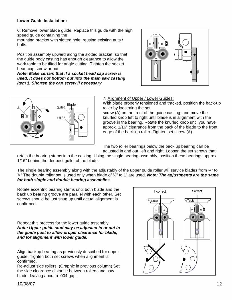
Lower Guide Installation: 6: Remove lower blade guide. Replace this guide with the high speed guide containing the mounting bracket with slotted hole, reusing existing nuts / bolts. Position assembly upward along the slotted bracket, so that the guide body casting has enough clearance to allow the work table to be tilted for angle cutting. Tighten the socket head cap screw or nut. Note: Make certain that if a socket head cap screw is used, it does not bottom out into the main saw casting item 1. Shorten the cap screw if necessary
7: Alignment of Upper / Lower Guides: With blade properly tensioned and tracked, position the back-up roller by loosening the set screw (A) on the front of the guide casting, and move the knurled knob left to right until blade is in alignment with the groove in the bearing. Rotate the knurled knob until you have approx. 1/16” clearance from the back of the blade to the front edge of the back-up roller. Tighten set screw (A). The two roller bearings below the back up bearing can be adjusted in and out, left and right. Loosen the set screws that
retain the bearing stems into the casting. Using the single bearing assembly, position these bearings approx. 1/16” behind the deepest gullet of the blade. The single bearing assembly along with the adjustably of the upper guide roller will service blades from ¼” to ¾” The double roller set is used only when blade of ½” to 1” are used. Note: The adjustments are the same for both single and double bearing assemblies. Rotate eccentric bearing stems until both blade and the back up bearing groove are parallel with each other. Set screws should be just snug up until actual alignment is confirmed. Repeat this process for the lower guide assembly. Note: Upper guide stud may be adjusted in or out in the guide post to allow proper clearance for blade, and for alignment with lower guide. Align backup bearing as previously described for upper guide. Tighten both set screws when alignment is confirmed. Re-adjust side rollers. (Graphic in previous column) Set the side clearance distance between rollers and saw blade, leaving about a .004 gap.
10/08/07 13
Note: If the adjustment setting for side clearance between roller and blade is not enough, the side rollers will cause the blade to miss-track or be pushed outward from the guide rollers. Note: If blade alignment from band wheel to roller guides is necessary, do so by rotating eccentric shafts on the roller guides. Then lock them in place with the set screws. After all adjustments have been made, tighten all components tight.
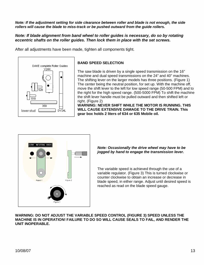
BAND SPEED SELECTION The saw blade is driven by a single speed transmission on the 16” machine and dual speed transmissions on the 24” and 40” machines. The shifting lever on the larger models has three positions. (Figure 1) The center being the neutral position, for set up. With the machine off, move the shift lever to the left for low speed range (50-500 FPM) and to the right for the high speed range. (500-5000 FPM) To shift the machine the shift lever handle must be pulled outward and then shifted left or right. (Figure 2) WARNING: NEVER SHIFT WHILE THE MOTOR IS RUNNING. THIS WILL CAUSE EXTENSIVE DAMAGE TO THE DRIVE TRAIN. This gear box holds 2 liters of 634 or 635 Mobile oil.
Note: Occasionally the drive wheel may have to be jogged by hand to engage the transmission lever. The variable speed is achieved through the use of a variable regulator. (Figure 3) This is turned clockwise or counter clockwise to obtain an increase or decrease in blade speed, in either range. Adjust until desired speed is reached as read on the blade speed gauge.
WARNING: DO NOT ADJUST THE VARIABLE SPEED CONTROL (FIGURE 3) SPEED UNLESS THE MACHINE IS IN OPERATION! FAILURE TO DO SO WILL CAUSE SEALS TO FAIL, AND RENDER THE UNIT INOPERABLE.

10/08/07 14
SAW BLADE SELECTION There are numerous types of saw blades available depending upon the application. Tooth pitch, form, tooth set, and blade composite make up all contribute to the desired cut. Blade speeds and feed are also a factors. The complexity of the subject cannot be properly detailed in this manual, and it is suggested that you contact your local blade supplier for more detailed information and recommendations for the application. Below is a chart that can be used as a guide line for blade selection and a percentage chart for determining the speeds and feeds for material after determining the Rockwell hardness. The chart below shows material shape and sizes of square solid, round solid, and tubing, channel, and angle. The size range from 0” - 12” is diameter; the column under the shapes gives recommendation of a vari-tooth blade. Example: 4” round solid, will require a 3/4 pitch blade. Note: For structurals and tubing, determine the average width of cut. Blades must be broke in properly, for longest life and best cut finish. Break in cutting should be done at 1/3-1/2 normal cutting rate, for the 50-100 square inches. NOTE: Below are the three most commonly used types of blades. The Bi-Metal blade is the most durable, for standard types of cutting applications. The teeth are made of high speed steel and welded to a backing material. The cutting edge contains 8% cobolt with a Rc of 64 to 68. (These blades are more difficult to weld than standard carbon.) The carbon blade is the least expensive with reduced blade life. The back of the blade is made of hardened material with a Rc of 31 to 37 and tooth hardness of 64 to 66. The carbide tipped blade has carbide inserts welded to the blade teeth with a Ra rating of 92 SPEEDS AND FEEDS As important as proper blade selection, is proper feeds and speeds for the different materials to be cut. It is impossible to determine absolute rates for each material and machine, below is a chart that will give you staring points for most applications; keeping in mind these are only approximations. The left hand column, labeled Material tells you the family, the column Alloy lists the types that are within that family of material. The top six columns give material dimensions. Below these column are listed the recommended FPM and SIPM for that material type. Example: Carbon steel with a alloy make up classified as 1030, with a diameter of 4” will be cut at 329 FPM and SIPM of 14, shown as fpm 329 sipm 14.

10/08/07 15
BAND SPEED SELECTION
MATERIAL SHAPE MATERIAL SHAPE MATERIAL SHAPE
MATERIAL IN
INCHES TOOTH SELECTION TOOTH SELECTION TOOTH SELECTION
0 14 / 18 14 / 18 14 / 18 .1 14 / 18 14 / 18 14 / 18 .2 14 / 18 14 / 18 14 / 18 .3 10 / 14 14 / 18 10 / 14 .4 8 / 12 10 / 14 8 / 12 .5 8 / 12 8 / 12 6 / 10 .6 6 / 10 8 / 12 5 / 8 .7 6 / 10 6 / 10 5 / 8 .8 5 / 8 6 / 10 5 / 8 .9 5 / 8 5 / 8 5 / 8 1 5 / 8 5 / 8 4 / 6
1 1/4 4 / 6 5 / 8 4 / 6 1 1/2 4 / 6 4 / 6 4 / 6 1 3/4 4 / 6 4 / 6 4 / 6
2 4 / 6 4 / 6 3 / 4 2 1/4 4 / 6 4 / 6 3 / 4 2 1/2 3 / 4 4 / 6 3 / 4 2 3/4 3 / 4 4 / 6 3 / 4
3 3 / 4 3 / 4 3 / 4 3 1/4 3 / 4 3 / 4 3 / 4 3 1/2 3 / 4 3 / 4 3 / 4 3 3/4 3 / 4 3 / 4 2 / 3
4 3 / 4 3 / 4 2 / 3 5 2 / 3 3 / 4 2 / 3 6 2 / 3 3 / 4 2 / 3 7 2 / 3 2 / 3 1.4 / 2.5 8 1.4 / 2.5 2 / 3 1.4 / 2.5 9 1.4 / 2.5 2 / 3 1.4 / 2.5
10 1.4 / 2.5 1.4 / 2.5 1.4 / 2.5 11 1.4 / 2.5 1.4 / 2.5 1.4 / 2.5
(Optional) HYDRAULIC FEED TABLE Machines equipped with a hydraulic feed table (VH models) have a pumping unit in the base. The system has an adjustable relief valve, which is factory preset at 400 p.s.i. This setting may be reduced to afford greater sensitivity for cutting soft or thin materials. Pressures may be lowered by turning the square nut located on the top right hand side of the reservoir. (See below graphic) The systems oil level must be checked periodically to assure the oil levels are maintained at the full level of the sight glass. This should hold 6 liters of DTE 26.
10/08/07 16
BANDSAW WELDING CURRENT
UPSETTING PRESSURE
UPSETTING WAY
ANNEALING ANNEALING
mm step *) step *) mm COLOR TIME SEC.
6 x 0.9 1 - 2 1 2.5 DARK RED 15
10 x 0.9 1 - 2 1 3.0 DARK RED 15
12 x 0.6 1 - 2 1 3.0 DARK RED 15
12 x 0.9 1 - 2 1 3.0 DARK RED 15
13 x 0.7 1 - 2 1 - 2 3.0 DARK RED 15
16 x 0.7 1 - 2 1 - 2 3.0 DARK RED 15
19 x 0.9 1 - 2 1 - 2 3.0 DARK RED 15
25 x 0.9 1 - 2 1 - 2 3.5 DARK RED 15
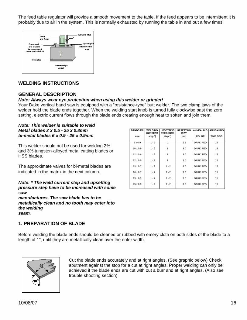
The feed table regulator will provide a smooth movement to the table. If the feed appears to be intermittent it is probably due to air in the system. This is normally exhausted by running the table in and out a few times.
WELDING INSTRUCTIONS GENERAL DESCRIPTION Note: Always wear eye protection when using this welder or grinder! Your Dake vertical band saw is equipped with a “resistance-type” butt welder. The two clamp jaws of the welder hold the blade ends together. When the welding start knob is turned fully clockwise past the zero setting, electric current flows through the blade ends creating enough heat to soften and join them. Note: This welder is suitable to weld Metal blades 3 x 0.5 - 25 x 0.8mm bi-metal blades 6 x 0.9 - 25 x 0.9mm This welder should not be used for welding 2% and 3% tungsten-alloyed metal cutting blades or HSS blades. The approximate valves for bi-metal blades are indicated in the matrix in the next column. Note: * The weld current step and upsetting pressure step have to be increased with some saw manufactures. The saw blade has to be metallically clean and no tooth may enter into the welding seam. 1. PREPARATION OF BLADE Before welding the blade ends should be cleaned or rubbed with emery cloth on both sides of the blade to a length of 1”, until they are metallically clean over the enter width.
Cut the blade ends accurately and at right angles. (See graphic below) Check abutment against the stop for a cut at right angles. Proper welding can only be achieved if the blade ends are cut with out a burr and at right angles. (Also see trouble shooting section)
10/08/07 17
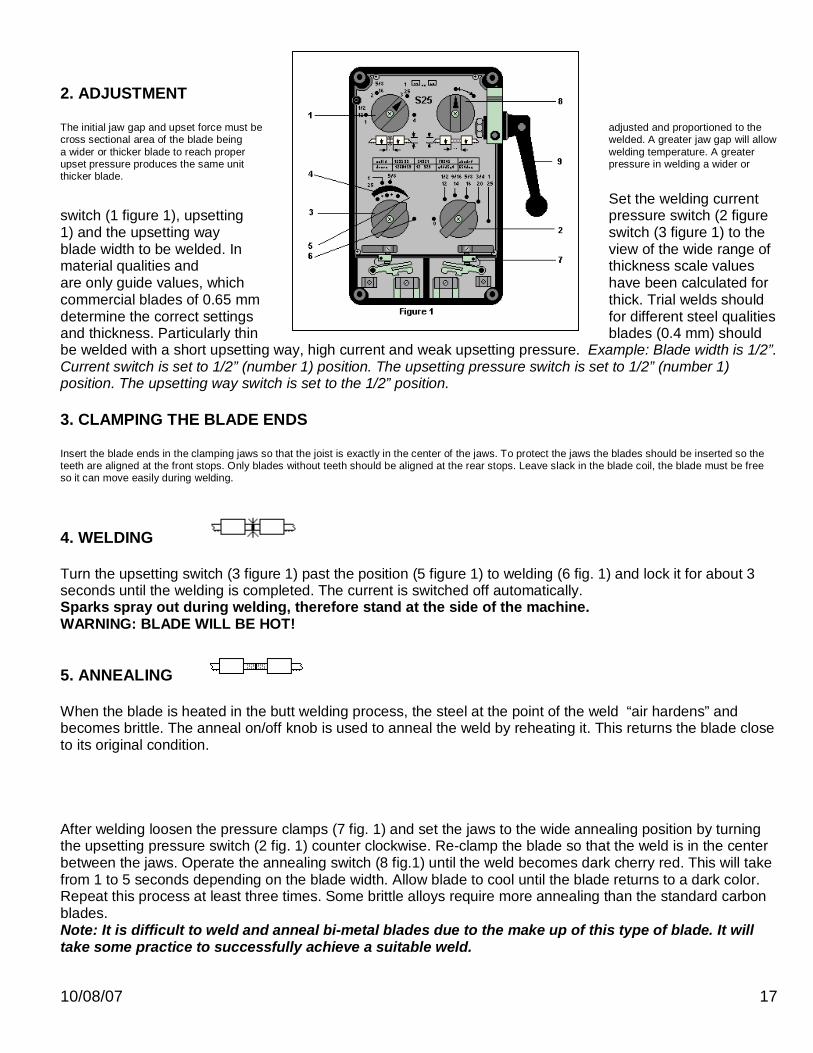
2. ADJUSTMENT The initial jaw gap and upset force must be adjusted and proportioned to the cross sectional area of the blade being welded. A greater jaw gap will allow a wider or thicker blade to reach proper welding temperature. A greater upset pressure produces the same unit pressure in welding a wider or thicker blade.
Set the welding current switch (1 figure 1), upsetting pressure switch (2 figure 1) and the upsetting way switch (3 figure 1) to the blade width to be welded. In view of the wide range of material qualities and thickness scale values are only guide values, which have been calculated for commercial blades of 0.65 mm thick. Trial welds should determine the correct settings for different steel qualities and thickness. Particularly thin blades (0.4 mm) should be welded with a short upsetting way, high current and weak upsetting pressure. Example: Blade width is 1/2”. Current switch is set to 1/2” (number 1) position. The upsetting pressure switch is set to 1/2” (number 1) position. The upsetting way switch is set to the 1/2” position. 3. CLAMPING THE BLADE ENDS Insert the blade ends in the clamping jaws so that the joist is exactly in the center of the jaws. To protect the jaws the blades should be inserted so the teeth are aligned at the front stops. Only blades without teeth should be aligned at the rear stops. Leave slack in the blade coil, the blade must be free so it can move easily during welding.
4. WELDING Turn the upsetting switch (3 figure 1) past the position (5 figure 1) to welding (6 fig. 1) and lock it for about 3 seconds until the welding is completed. The current is switched off automatically. Sparks spray out during welding, therefore stand at the side of the machine. WARNING: BLADE WILL BE HOT! 5. ANNEALING When the blade is heated in the butt welding process, the steel at the point of the weld “air hardens” and becomes brittle. The anneal on/off knob is used to anneal the weld by reheating it. This returns the blade close to its original condition. After welding loosen the pressure clamps (7 fig. 1) and set the jaws to the wide annealing position by turning the upsetting pressure switch (2 fig. 1) counter clockwise. Re-clamp the blade so that the weld is in the center between the jaws. Operate the annealing switch (8 fig.1) until the weld becomes dark cherry red. This will take from 1 to 5 seconds depending on the blade width. Allow blade to cool until the blade returns to a dark color. Repeat this process at least three times. Some brittle alloys require more annealing than the standard carbon blades. Note: It is difficult to weld and anneal bi-metal blades due to the make up of this type of blade. It will take some practice to successfully achieve a suitable weld.

10/08/07 18
WARNING: BLADE WILL BE HOT! After annealing bend test your weld:
6. RE-FINISHING THE WELD Welding burr (flash) can be removed by finishing with a grinding wheel above the welder. Grind in a longitudinal direction, other wise transverse fractures may occur. The proper finish of the blade after grinding, a tempered steel-blue coloring. Note: Do not over grind, into the blade facing. Remove any burr on the back edge of the blade.
WELDER LAYOUT AND CONTROLS 7. WELDER MAINTENANCE If the clamping areas of the jaws are dirty or deformed so they so not clamp evenly, good welds cannot be made. Any dirt or metallic debris must be removed from the jaws. The jaws should never be filed. It should only be polished with a proper cleaning material and if absolutely necessary polished with fine emery cloth held on a flat piece of bar stock. The uniformity of current flow and contact pressure can be checked by putting the welder in the annealing position and clamping a piece of blade stock with out a weld in the jaws. When the annealing switch is turned to the heating position the blade should heat uniformly over its entire width. (See fig. 2) If the heating is not uniform the clamping devices should be checked for dirt or misalignment. figure 2 8. POOR WELDS / TROUBLE SHOOTING If the welded seam contains holes, the upsetting pressure should be increased, the welding current reduced or both settings changed. We must emphasize once again that proper welds cannot be made if the blade ends are not cut square, and properly cleaned. Welding of blades may take practice, do not be discouraged if your welds are not perfect at first. Avoid overlapping when welding thin blades. If welder does not give suitable weld, check in coming voltage to the machine. If voltage is low, use next blade size setting. Example: 220 volt machine, incoming voltage is 208 volt, to weld 1/2” blade use 5/8” settings. If incoming voltage is high reverse this procedure. If incoming voltage is low, the welder transformer has taps that can be set to a 10% increase or decrease. SHOCK HAZARD! ONLY A QUALIFIED ELECTRICIAN SHOULD ATTEMPT THIS. ALWAYS CONTACT DAKE BEFORE REMOVING THE WELDER. If the welder does not shut off, after the welding cycle, or will not start the welding cycle, a limit switch adjustment is needed. THE WELDER MUST BE REMOVED FOR THIS ADJUSTMENT. SHOCK HAZARD! ALWAYS CONTACT DAKE BEFORE REMOVING THE WELDER OF MAKING INTERNAL ADJUSTMENTS. A QUALIFIED ELECTRICIAN MUST DO THESE ADJUSTMENT.
10/08/07 19
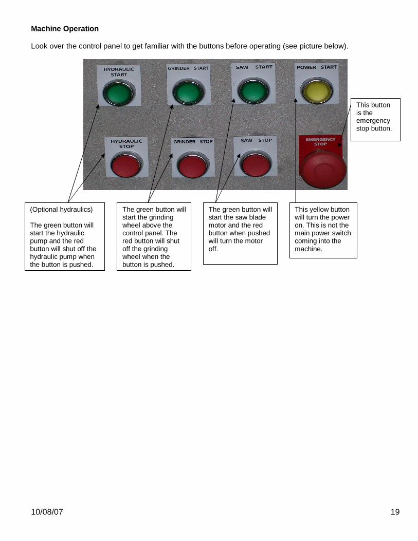
Machine Operation Look over the control panel to get familiar with the buttons before operating (see picture below).
(Optional hydraulics) The green button will start the hydraulic pump and the red button will shut off the hydraulic pump when the button is pushed.
The green button will start the grinding wheel above the control panel. The red button will shut off the grinding wheel when the button is pushed.
The green button will start the saw blade motor and the red button when pushed will turn the motor off.
This yellow button will turn the power on. This is not the main power switch coming into the machine.
This button is the emergency stop button.
10/08/07 20
MACHINE OPERATION
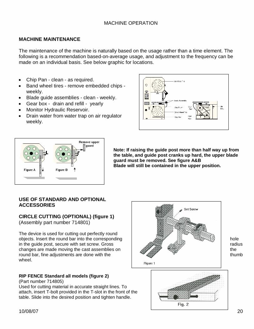
MACHINE MAINTENANCE The maintenance of the machine is naturally based on the usage rather than a time element. The following is a recommendation based-on-average usage, and adjustment to the frequency can be made on an individual basis. See below graphic for locations. Chip Pan - clean - as required. Band wheel tires - remove embedded chips -
weekly. Blade guide assemblies - clean - weekly. Gear box - drain and refill - yearly Monitor Hydraulic Reservoir. Drain water from water trap on air regulator
weekly.
Note: If raising the guide post more than half way up from the table, and guide post cranks up hard, the upper blade guard must be removed. See figure A&B Blade will still be contained in the upper position.
USE OF STANDARD AND OPTIONAL ACCESSORIES CIRCLE CUTTING (OPTIONAL) (figure 1) (Assembly part number 714801) The device is used for cutting out perfectly round objects. Insert the round bar into the corresponding hole in the guide post, secure with set screw. Gross radius changes are made moving the cast assemblies on the round bar, fine adjustments are done with the thumb wheel. RIP FENCE Standard all models (figure 2) (Part number 714805) Used for cutting material in accurate straight lines. To attach, insert T-bolt provided in the T-slot in the front of the table. Slide into the desired position and tighten handle.

10/08/07 21
PROFILE CUTTING ATTACHMENT Standard on VH-24 models (figure 3) (Part number 714821) This device is used for cutting irregular shapes with the use of the hydraulic table. Set the chain up as shown in figure 3. Set the material in the holder and guide with the hand wheel on the right side of the table. The excess chain should be coiled out of the way, while operating the machine. Note: When chain is not engaged in the rear sprocket the angle of cut is controlled by guiding the handles on the holder. PROTRACTOR HEAD Standard (figure 4) (Assembly Part number 714800) Used for cutting angles 90 degrees to 45 degrees in relation to the blade. It is fastened to the table by means of T-bolts. The L-shaped bar is used for additional support of the work. T-SLOTS T-slots are machine into the work table for your use with fixturing or other accessories. The dimensions of these T-slots are furnished to the right.
10/08/07 22
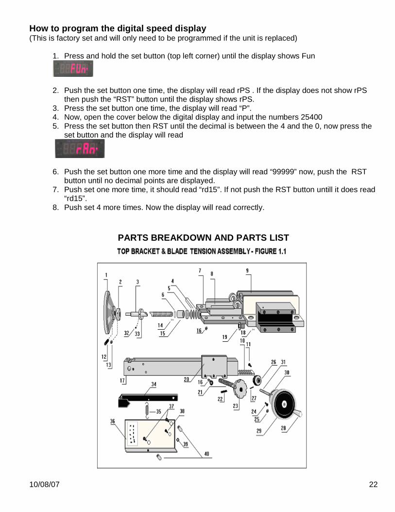
How to program the digital speed display (This is factory set and will only need to be programmed if the unit is replaced)
1. Press and hold the set button (top left corner) until the display shows Fun
2. Push the set button one time, the display will read rPS . If the display does not show rPS then push the “RST” button until the display shows rPS.
3. Press the set button one time, the display will read “P”. 4. Now, open the cover below the digital display and input the numbers 25400 5. Press the set button then RST until the decimal is between the 4 and the 0, now press the
set button and the display will read
6. Push the set button one more time and the display will read “99999” now, push the RST
button until no decimal points are displayed. 7. Push set one more time, it should read “rd15”. If not push the RST button untill it does read
“rd15”. 8. Push set 4 more times. Now the display will read correctly.
PARTS BREAKDOWN AND PARTS LIST

10/08/07 23
Figure 1.1
ITEM PART NAME PART NO. V-24
1 Hand wheel 81529 1 2 Adjusting Wheel Collar 81531 1 3 Spindle 81533 1 4 Crown Spring 81535 6 5 Axial Bearing 81537 1 6 Spacer 81539 1 7 Lath Gib 81541 2 8 Carriage 81543 1 9 Carriage Lower Portion 81545 1 10 Rack 81547 1 11 Screw 4mm x 16mm 81548 2 12 Pin 81549 1 13 Set Screw 8mm x 10mm 81550 1 14 Flat Head Screw 4mm x 6mm 81551 2 15 Needle Bearing K25x30x39 2W 81553 1 16 Screw 8mm x 20mm 80521 11 17 Guide Post 81557 1 18 Set Screw 10mm x 20mm 81560 1 19 Threaded Sleeve 81558 4 20 Plate 81562 1 21 Handle Bolt 81563 1 22 Roll Pin 81654 1 23 Star Handle 81565 1 24 Cap Screw 6mm x 12mm 80625 3 25 Set Screw 6mm x 10mm 8 pitch 80529 1 26 Gear 81567 1 27 Roll Pin 81568 1 28 Handle 80501 1 29 Hand Wheel 80500 1 30 Flange 81569 1 31 Hand Wheel Adjusting Bolt 81570 1 32 Tension Collar Set Screw 1 33 Tension Indicator Collar 1 34 Tension Indicator Pointer Rod 81973 1 35 Indicator Pointer Return Spring 716500 1 36 Indicator Plate 1 37 Mounting Bolts 1 38 Pivot Bolt 2 39 Pivot Bolt Nut 1 40 Plate Spacers 2
10/08/07 24
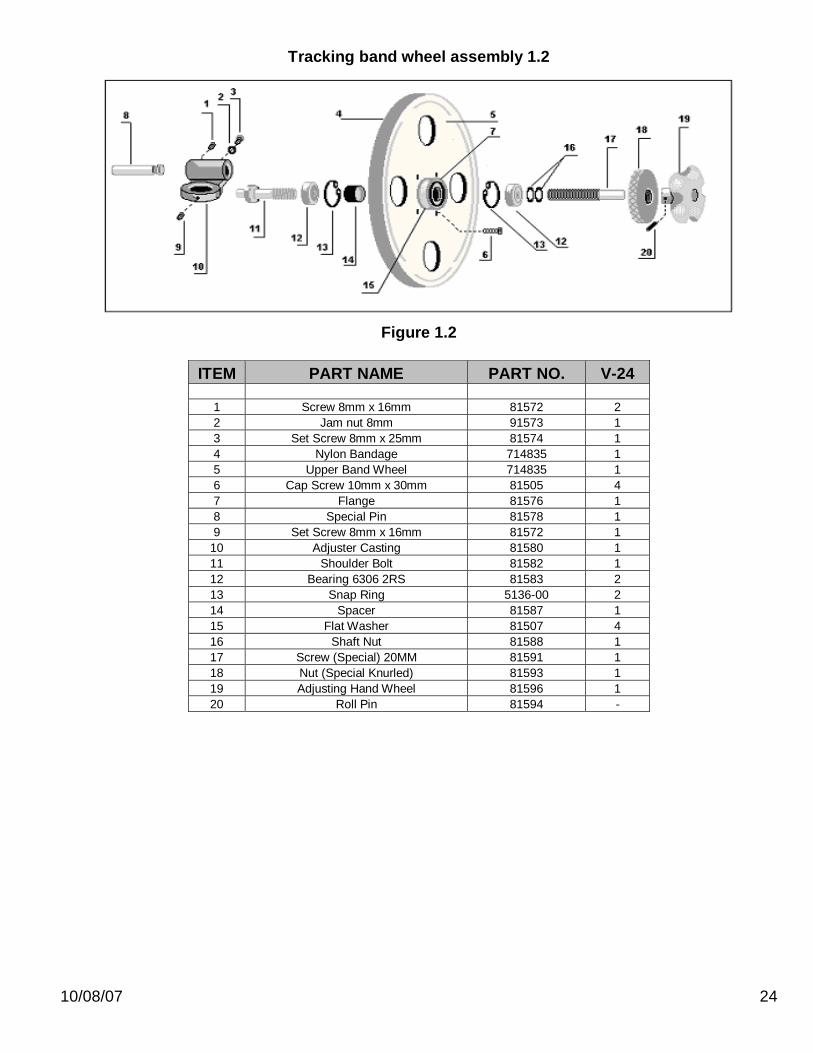
Tracking band wheel assembly 1.2
Figure 1.2
ITEM PART NAME PART NO. V-24
1 Screw 8mm x 16mm 81572 2 2 Jam nut 8mm 91573 1 3 Set Screw 8mm x 25mm 81574 1 4 Nylon Bandage 714835 1 5 Upper Band Wheel 714835 1 6 Cap Screw 10mm x 30mm 81505 4 7 Flange 81576 1 8 Special Pin 81578 1 9 Set Screw 8mm x 16mm 81572 1
10 Adjuster Casting 81580 1 11 Shoulder Bolt 81582 1 12 Bearing 6306 2RS 81583 2 13 Snap Ring 5136-00 2 14 Spacer 81587 1 15 Flat Washer 81507 4 16 Shaft Nut 81588 1 17 Screw (Special) 20MM 81591 1 18 Nut (Special Knurled) 81593 1 19 Adjusting Hand Wheel 81596 1 20 Roll Pin 81594 -

10/08/07 25
Optional Hydraulic
Figure 2.2
ITEM PART NAME PART NO. V-24 1 Bracket 81702 1 2 Guide Rod 81703 2 3 Guide Casting 81704 1 4 Cap Screw 8mm x 25mm 81705 3 5 Cap Screw 6mm x 20mm 64179 2 6 Cap Screw 81707 1 7 Blade Guide Bracket Casting 81708 2 8 Table Cradle Lower part 81709 1 9 Special Rotaion Bolt 81710 1 10 Flat Washer 81711 1 11 Nut 81712 1 12 Roll Pin 8mm x 10mm 81743 1 15 Needle Bearing K20x24x17 81552 1 16 Screw 8mm x 20mm 80521 9 17 Guide Post 81555 1 19 Threaded Sleeve 81558 4 20 Plate 81561 1 23 Star Handle 81565 1 24 Cap Screw 6mm x 12mm 80625 3 25 Set Screw 6mm x 10mm 8 pitch 80529 1 31 Hand Wheel Adjusting Bolt 81570 1 32 Tension Collar Set Screw 1 33 Tension Indicator Collar 1 34 Tension Indicator Pointer Rod 81973 1 36 Indicator Plate 1 37 Mounting Bolts 1 38 Pivot Bolt 2 39 Pivot Bolt Nut 1 40 Plate Spacers 2
10/08/07 26
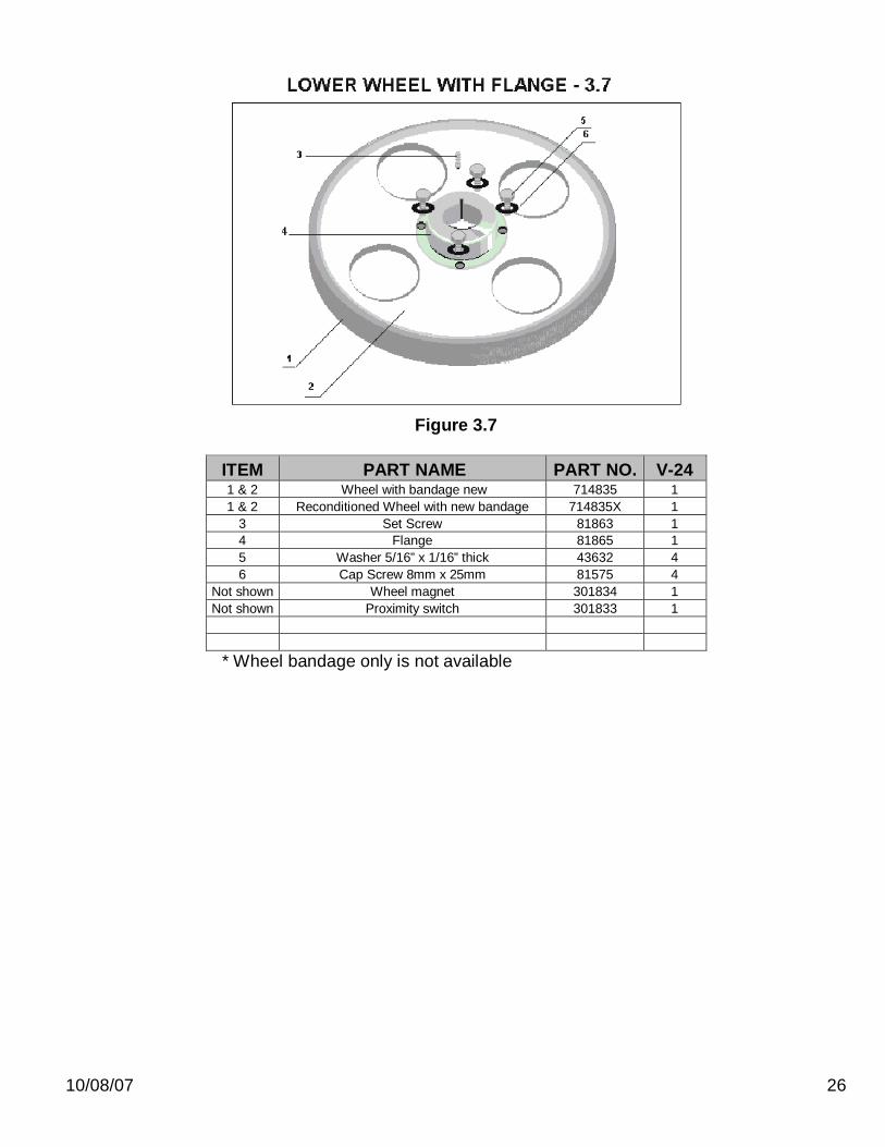
Figure 3.7
ITEM PART NAME PART NO. V-24 1 & 2 Wheel with bandage new 714835 1 1 & 2 Reconditioned Wheel with new bandage 714835X 1
3 Set Screw 81863 1 4 Flange 81865 1 5 Washer 5/16” x 1/16” thick 43632 4 6 Cap Screw 8mm x 25mm 81575 4
Not shown Wheel magnet 301834 1 Not shown Proximity switch 301833 1
* Wheel bandage only is not available
10/08/07 27
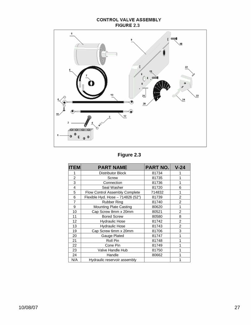
Figure 2.3
ITEM PART NAME PART NO. V-24
1 Distributor Block 81734 1 2 Screw 81735 1 3 Connection 81736 1 4 Seal Washer 81720 6 5 Flow Control Assembly Complete 714832 1 6 Flexible Hyd. Hose – 714826 (52”) 81739 2 7 Rubber Ring 81740 2 9 Mounting Plate Casting 80620 1 10 Cap Screw 8mm x 20mm 80521 2 11 Bored Screw 80580 8 12 Hydraulic Hose 81742 2 13 Hydraulic Hose 81743 2 19 Cap Screw 6mm x 20mm 81706 3 20 Gauge Plated 81747 1 21 Roll Pin 81748 1 22 Cone Pin 81749 1 23 Valve Handle Hub 81750 1 24 Handle 80662 1
N/A Hydraulic reservoir assembly 1
10/08/07 28
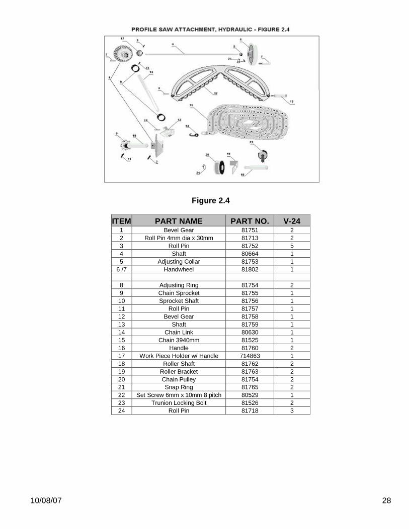
Figure 2.4
ITEM PART NAME PART NO. V-24 1 Bevel Gear 81751 2 2 Roll Pin 4mm dia x 30mm 81713 2 3 Roll Pin 81752 5 4 Shaft 80664 1 5 Adjusting Collar 81753 1
6 /7 Handwheel 81802 1
8 Adjusting Ring 81754 2 9 Chain Sprocket 81755 1 10 Sprocket Shaft 81756 1 11 Roll Pin 81757 1 12 Bevel Gear 81758 1 13 Shaft 81759 1 14 Chain Link 80630 1 15 Chain 3940mm 81525 1 16 Handle 81760 2 17 Work Piece Holder w/ Handle 714863 1 18 Roller Shaft 81762 2 19 Roller Bracket 81763 2 20 Chain Pulley 81754 2 21 Snap Ring 81765 2 22 Set Screw 6mm x 10mm 8 pitch 80529 1 23 Trunion Locking Bolt 81526 2 24 Roll Pin 81718 3
10/08/07 29
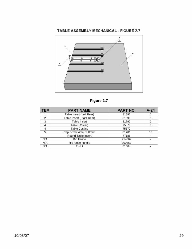
Figure 2.7
ITEM PART NAME PART NO. V-24 1 Table Insert (Left Rear) 81597 1 2 Table Insert (Right Rear) 81598 1 3 Table Insert 81792 2 4 Table Casting 75678 1 4 Table Casting 75677 - 5 Cap Screw 4mm x 12mm 81701 10 Round Table Insert 77186 -
N/A Rip Fence 714869 - N/A Rip fence handle 300362 - N/A T-Nut 81504 -
10/08/07 30
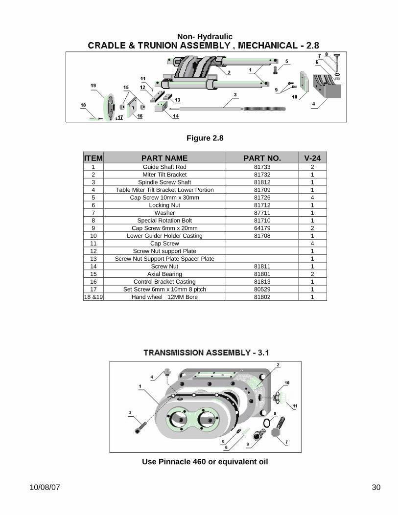
Non- Hydraulic
Figure 2.8
ITEM PART NAME PART NO. V-24 1 Guide Shaft Rod 81733 2 2 Miter Tilt Bracket 81732 1 3 Spindle Screw Shaft 81812 1 4 Table Miter Tilt Bracket Lower Portion 81709 1 5 Cap Screw 10mm x 30mm 81726 4 6 Locking Nut 81712 1 7 Washer 87711 1 8 Special Rotation Bolt 81710 1 9 Cap Screw 6mm x 20mm 64179 2 10 Lower Guider Holder Casting 81708 1 11 Cap Screw 4 12 Screw Nut support Plate 1 13 Screw Nut Support Plate Spacer Plate 1 14 Screw Nut 81811 1 15 Axial Bearing 81801 2 16 Control Bracket Casting 81813 1 17 Set Screw 6mm x 10mm 8 pitch 80529 1
18 &19 Hand wheel 12MM Bore 81802 1
Use Pinnacle 460 or equivalent oil

10/08/07 31
ITEM PART NAME PART NO. V-24 1 Front Cover Plate 81819 1 2 Transmission Main Body Casting 81820 1 3 Cap Screw 8mm x 20mm 80521 8 4 Plug 81821 1 5 Set Screw 5mm x 7mm 81728 2 6 Alignment Roll Pin 81728 2 7 Hex Head Bolt 81822 4 8 Washer 81507 4 9 Threaded Adjustment Sleeve 81558 4 10 O-ring 1 x 1-3/16 x 3/32 81823 1 11 Oil Sight Glass 80571 1 Complete Transmission Assembly V-24/VH-24 714845 1
ITEM PART NAME PART NO. V-24 1 Roll Pin 81824 2 2 Lever 81825 1 3 Cap Screw 6mm x 20mm 81706 6 4 Cover Plate 81826 1 5 Special Bolt (Shift Lever) 81827 1 6 Gear Shifter Casting 81828 1 7 Snap Ring 81829 1 8 Guide Collar 81830 1 9 Nut 81831 2 10 Screw 81832 1 11 Shaft 81833 1 12 Gear Shaft Fork 81834 1 13 Screw 81835 1
Transmission Assembly – Figure 3.1
Transmission Assembly – Figure 3.2

10/08/07 32
ITEM PART NAME PART NO. V-24 1 Cap Screw 81707 3 2 End Cover 81836 1 3 Snip Ring 81837 2
4/9 Bearing SKF 6206-2RS 79465 2 5 Snap Ring 81839 1 6 Shaft 81840 1 7 Key 81841 1 8 Gear 81842 1
ITEM PART NAME PART NO. V-24 1 Snap Ring 81843 1 2 Bearing 80673 2 3 Shaft 81845 1 4 End Cover Plate 81849 1 5 Cap Screw 81707 3 6 Oil Seal 81846 1 7 Key 81847 1
Transmission, Gear Assembly – Figure 3.3
Transmission Assembly (Gears) – Figure 3.4

10/08/07 33
ITEM PART NAME PART NO. V-24 1 Oil Ring 81848 1 2 Cap Screw 81707 3 3 End Cover Plate 81849 1 4 Snap Ring 81837 1 5 Bearing BCA 5206K 81850 1 6 Snap Ring 81839 1 7 Key 81851 1 8 Spline Shaft 81852 1 Thrust Bearing 81855 1 Needle Bearing 300296 1
9 Gear 81853 1
ITEM PART NAME PART NO. V-24 1 Needle Bearing 81854 1 2 Shaft 81855 1 3 Key 81841 1 4 Bearing 81838 1 5 Spacer Ring 81856 1 6 Gear 81857 - 6 Gear 81858 1 7 Spacer Ring 81859 1 8 Snap Ring 81843 1 9 Bearing 80673 1 10 End Cover Plate 80643 1 11 Cap Screw 81707 3 12 Oil Seal 81846 1 13 Set Screw 81741 1 14 Snap Ring 81860 1
Transmission Assembly (Gears) – Figure 3.5
Transmission Assembly (Gears) – Figure 3.6

10/08/07 34
ITEM PART NAME PART NO. V-24 1 Lever Casting 81825 1 2 Roll Pin 81824 3 3 Lever Casting 80530 1 4 Jam Nut 81866 4 5 Ball Joint 81867 2 6 Washer 81507 2 7 Shaft 81869 1 8 Shaft 81872 1 9 Screw 81741 1 10 Snap Ring 81874 1 11 Washer 81875 1 12 Spring 81876 1 13 Collar 81877 1 14 Handle 81878 1 15 Special Bolt 81879 1
Gear Shift Assembly – Figure 3.8
10/08/07 35
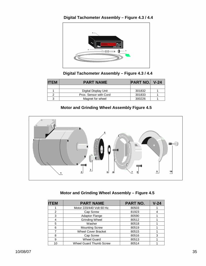
ITEM PART NAME PART NO. V-24 1 Digital Display Unit 301832 1 2 Prox. Sensor with Cord 301833 1 3 Magnet for wheel 300226 1
Motor and Grinding Wheel Assembly Figure 4.5
ITEM PART NAME PART NO. V-24 1 Motor 220/440 Volt 60 Hz. 80503 1 2 Cap Screw 81923 4 3 Adaptor Flange 80590 1 4 Grinding Wheel 80512 1 5 Washer 80518 1 6 Mounting Screw 80519 1 7 Wheel Cover Bracket 80515 1 8 Cap Screw 80516 3 9 Wheel Guard 80513 1 10 Wheel Guard Thumb Screw 80514 1
Digital Tachometer Assembly – Figure 4.3 / 4.4
Motor and Grinding Wheel Assembly – Figure 4.5
Digital Tachometer Assembly – Figure 4.3 / 4.4
10/08/07 36
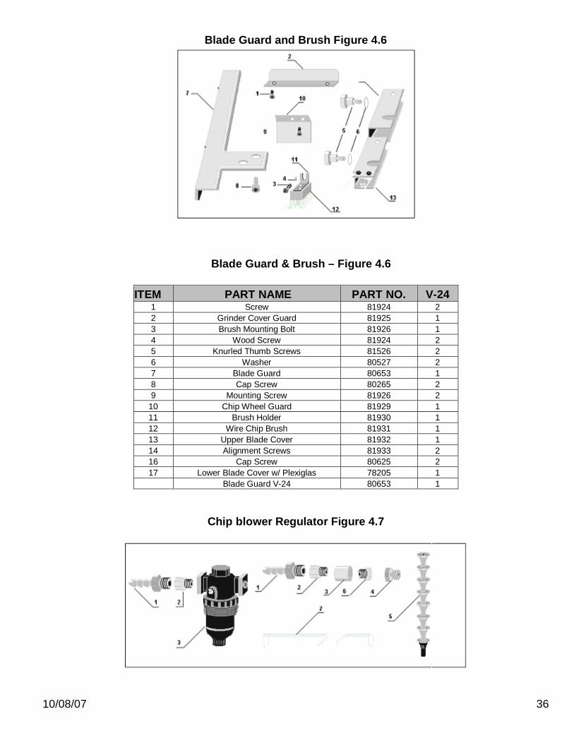
Blade Guard and Brush Figure 4.6
ITEM PART NAME PART NO. V-24 1 Screw 81924 2 2 Grinder Cover Guard 81925 1 3 Brush Mounting Bolt 81926 1 4 Wood Screw 81924 2 5 Knurled Thumb Screws 81526 2 6 Washer 80527 2 7 Blade Guard 80653 1 8 Cap Screw 80265 2 9 Mounting Screw 81926 2
10 Chip Wheel Guard 81929 1 11 Brush Holder 81930 1 12 Wire Chip Brush 81931 1 13 Upper Blade Cover 81932 1 14 Alignment Screws 81933 2 16 Cap Screw 80625 2 17 Lower Blade Cover w/ Plexiglas 78205 1 Blade Guard V-24 80653 1
Chip blower Regulator Figure 4.7
Blade Guard & Brush – Figure 4.6
10/08/07 37
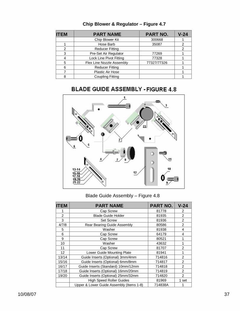
ITEM PART NAME PART NO. V-24 Chip Blower Kit 300668 1 1 Hose Barb 35087 2 2 Reducer Fitting 2 3 Pre-Set Air Regulator 77269 1 4 Lock Line Pivot Fitting 77328 1 5 Flex Line Nozzle Assembly 77327/77326 1 6 Reducer Fitting 1 7 Plastic Air Hose 1 8 Coupling Fitting 1
ITEM PART NAME PART NO. V-24 1 Cap Screw 81778 2 2 Blade Guide Holder 81935 2 3 Set Screw 81936 2
4/7/8 Rear Bearing Guide Assembly 80586 2 5 Washer 81938 4 6 Cap Screw 64179 4 9 Cap Screw 80521 1
10 Washer 43632 1 11 Cap Screw 81707 2 12 Lower Guide Mounting Plate 81941 1
13/14 Guide Inserts (Optional) 3mm/4mm 714816 2 15/16 Guide Inserts (Optional) 6mm/8mm 714817 2 16/17 Guide Inserts (Standard) 10mm/12mm 714818 2 17/18 Guide Inserts (Optional) 16mm/20mm 714819 2 19/20 Guide Inserts (Optional) 25mm/32mm 714820 2
High Speed Roller Guides 81969 1 set Upper & Lower Guide Assembly (Items 1-8) 714838A 1
Chip Blower & Regulator – Figure 4.7
Blade Guide Assembly – Figure 4.8
10/08/07 38
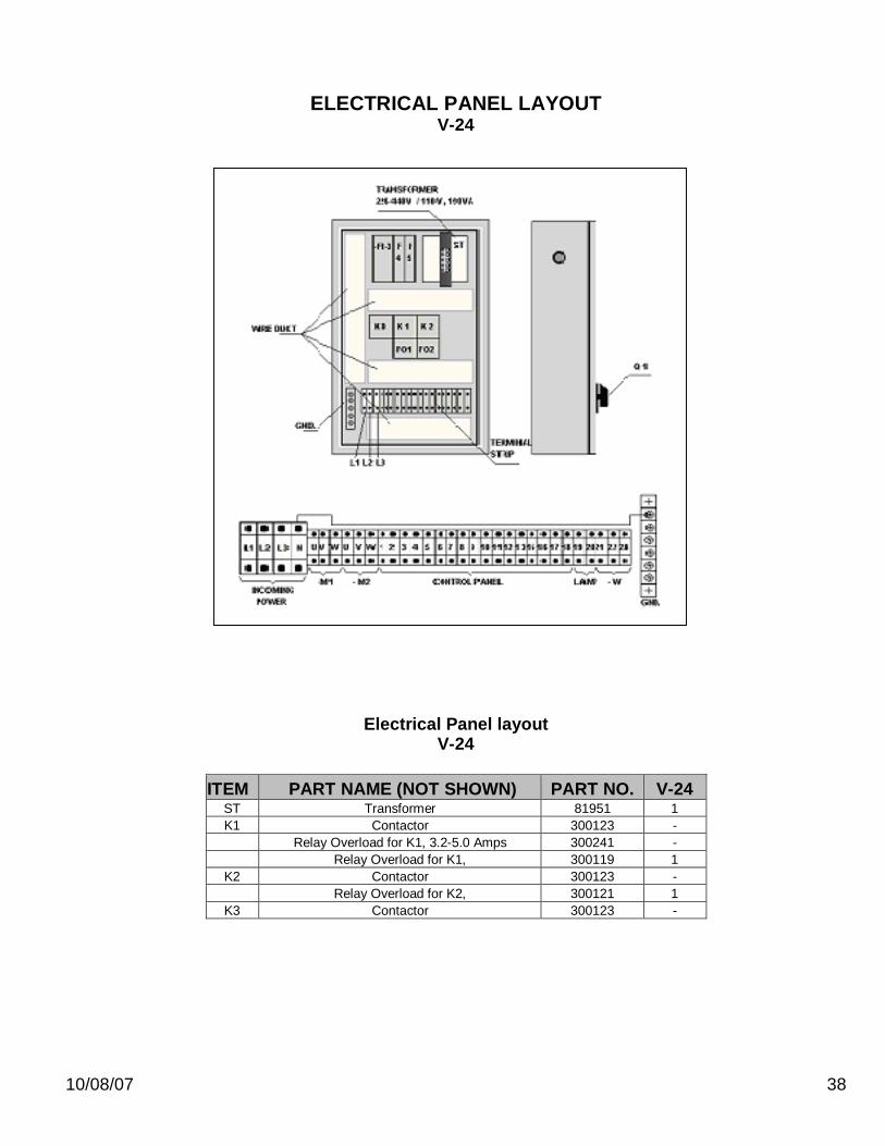
ELECTRICAL PANEL LAYOUT V-24
Electrical Panel layout V-24
ITEM PART NAME (NOT SHOWN) PART NO. V-24
ST Transformer 81951 1 K1 Contactor 300123 -
Relay Overload for K1, 3.2-5.0 Amps 300241 - Relay Overload for K1, 300119 1
K2 Contactor 300123 - Relay Overload for K2, 300121 1
K3 Contactor 300123 -

10/08/07 39
ELECTRICAL PANEL LAYOUT VH-24
ITEM PART NAME (NOT SHOWN) PART NO. VH-24 ST Transformer 1 K1 Contactor 300120 1
Relay Overload for K1 300119 1 K2 Contactor 300121 1
Relay Overload for K2 300121 1 K3 Contactor 300118 1
10/08/07 40
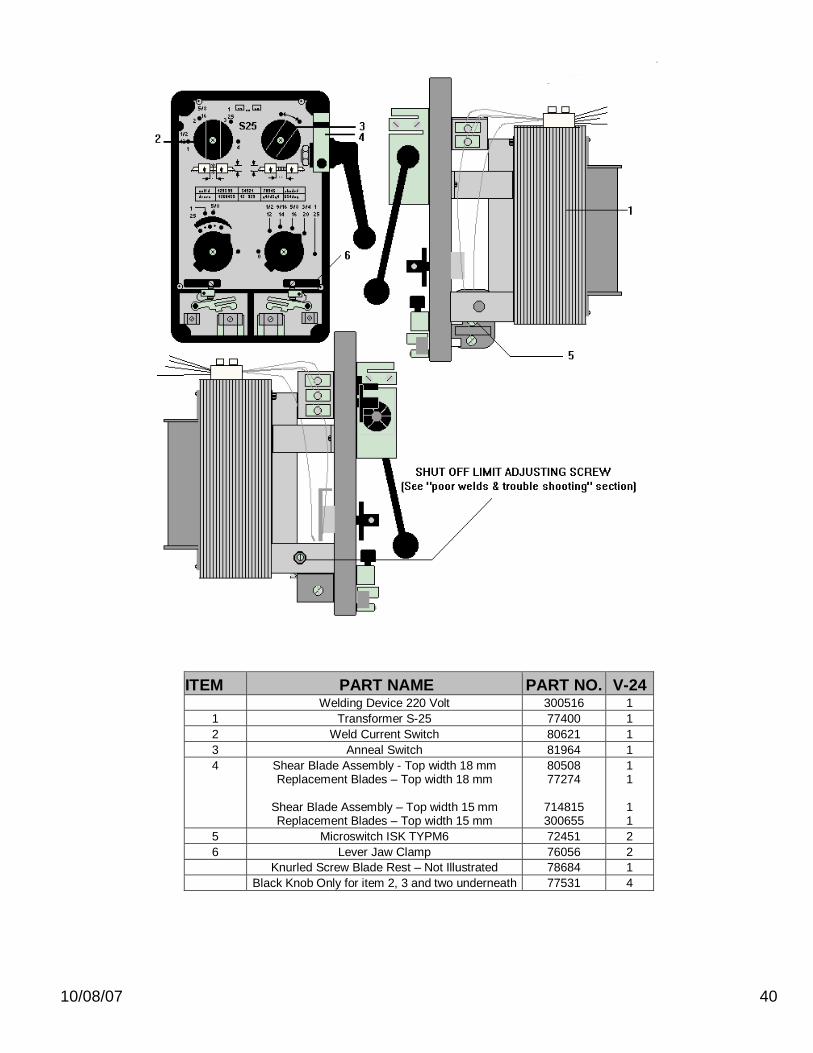
ITEM PART NAME PART NO. V-24 Welding Device 220 Volt 300516 1 1 Transformer S-25 77400 1 2 Weld Current Switch 80621 1 3 Anneal Switch 81964 1 4
Shear Blade Assembly - Top width 18 mm Replacement Blades – Top width 18 mm
Shear Blade Assembly – Top width 15 mm Replacement Blades – Top width 15 mm
80508 77274
714815 300655
1 1
1 1
5 Microswitch ISK TYPM6 72451 2 6 Lever Jaw Clamp 76056 2 Knurled Screw Blade Rest – Not Illustrated 78684 1 Black Knob Only for item 2, 3 and two underneath 77531 4

10/08/07 41
10/08/07 42

10/08/07 43