Embed Size (px)
Citation preview

Horizontal and Vertical
Metal Cutting Band Saw
OPERATION MANUAL
MODEL: BS-128DR
BS-128HDR

SAFETY
1. Know your bandsaw. Read the operator’s Manual carefully. Learn the
operations, applications and limitation as well as the specific potential
hazards peculiar to this band saw.
2. This unit is equipped with a three-prong (grounded) plug for your
protection against shock hazards and should be plugged directly into a
property grounded three-prong receptacle. Where a two-prong wall
receptacle is encountered. It must be replaced with a properly
grounded three prong receptacle in accordance with the
3. Use only 3-wire extension cords, which have 3-prong grounding type
plugs.
4. Replace or repair damage or worn cord immediately.
5. Keep guards in place and in working order.
6. Be especially careful when using bank saw in vertical position to keep
fingers and hands out of path of path of blade.
7. Wear ear protection if exposed to long periods of very noisy shop
operations.
8. Use safety goggles, hard hat and safety shoes. Also use face or dust
mask if cutting operation is dusty.
9. Wear proper apparel. No loose clothing or jewelry to get caught in
moving parts. Do not wear a tie or gloves.
10. Don’t overreach. Keep your proper footing and balance at all times.
11. Secure work. Always use the vise to hold work. Clamp securely. Never
hand-hold the work with saw in horizontal position.
12. Keep work area clean. Cluttered areas and benches invite accidents.
13. Avoid dangerous environment. Don not use the band saw in damp or
wet location. Keep work area well illuminated.
14. Don’t force tool. It will do the job better and safer at in the rate for
which it was designed.
15. Disconnect power cord before adjusting and servicing and before
changing blade.
16. Safety is combination of operator common sense and alertness at all
times when the saw is being used.
17. Never stand on tool. Serious injury could occur if the tool is tipped or if
the cutting tool is accidentally contacted.
18. Check damaged parts. Before further use of the tools, a guard or other
parts that it will operate to assure that it will operate properly
19. and perform its intend function-check for alignment of moving parts;
binding of moving parts, breakage of parts, mounting and any other

conditions that may affect its operation. A guard or other part that is
damaged should be properly repaired or replaced.
20. When moving the saw, ALWAYS have the head lowered to the
horizontal position.
SPECIFICATION:
Model BS-128DR BS-128HDR
Motor 1/3 OR 1/2HP
Blade size 12.7x0.64x1638mm
Blade
speed
60Hz(MPM) 24, 47, 61
50Hz(MPM) 20, 29, 50
60° ○ (mm) 44
□ (mm) 44x56
45° ○ (mm) 95
□ (mm) 75x95
0° ○ (mm) 128
□ (mm) 128x150
Dimension (mm) 980x385x1060
N.W./G.W. (kg) 110/140
Packing size (mm) 980x750x640
FEATURES
1. Special designed horizontal and vertical band saw.
2. Offers three speeds for cutting metal plastic or wood.
3. Shuts off automatically when material is cut.
4. With scale for the mitering vise.
5. No noise while operating.
6. Casters (optional) quick and easy moving.
7. Quick positioning vise provides easy clamping on work piece.
8. Built-in shelf for storing tools.
9. Both floor & bench have wheels for easy movement.
TELL TALE CHIPS
Chips are the best indicator of correct feed force. Monitor chip information
and adjust feed accordingly. Thin or powdered chips- increase feed rate or
reduce band speed.

Burned heavy
Chips-reduce feed rate and/or band speed.
Curly silvery and warm chips-optimum
Feed rate and band speed.
ASSEMBLY
A 1/3 or 1/2 HP motor split phase or capacitor start is recommended for
best economical performance. Counter clockwise is required. Note that
rotation can be reversed by following directions given on terminal or name
plate.
1. Assemble the motor Mounting plate to the head using the long bolt.
Note that the flat side of the plate faces up.
2. Assemble the guard plate to the head using the screw and lock washer
and the carriage bolt. Washer and wing nut are used to secure the
motor mounting plate to the guard plate through the slotted hole in the
guard plate. These components also serve to position and lock the
motor in place or proper speed/belt adjustment.
3. Place the spacer over the long bolt and secure it with the nut.
4. Secure the motor to the motor mounting plate with the four volts and
nuts. Note that the motor shaft is placed through the large opening in
the guard plate and must be parallel with the drive shaft.
5. Assemble the motor pulley, the smaller of the two provided to the motor
shaft. Note the larger diameter must be closest to the motor. Do not
tighten the set screw.
6. Assemble the driven pulley, the larger off the two provided to the
protruding drive shaft. Note the smaller diameter must be closest to the
bearing. Do not tighten the set screw.
7. Place the belt into one of the pulley groove and the other end into the
respective grooves of the second pulley.
8. Line up the belt and both pulleys such that the belt is running parallel in
the pulley grooves.
9. Tighten the set screws of both pulleys in this position.
10. Place the belt into proper pulley combination for proper blade speed.
See material cutting chart.
11. Adjust the position of the motor to obtain approximately 1/2’’
depression in the belt when applying pressure with your thumb.
12. Tighten the head screw holding the motor mounting plate to the guard
plate.
13. Connect the electrical harness to the motor terminal box. The motor
should be protected with a time delay fuse or circuit breaker with a
rated amperage slightly greater than the full-load amperage of the
motor.
OPERATION
WORK SET UP
1. Raise the saw head to vertical position.
2. Open vise to accept the piece to be cut by rotating the wheel at the end
of the base.
3. Place workpiece on saw bed. If the piece is long support the end.
4. Clamp workpiece securely in vise
WORK STOP ADJUSTMENT
1. Loose the thumb holding the work stop casting to the shaft.
2. Adjust the work stop casting to the desired length position.
3. Rotate the work stop to as close to the bottom of the cut as possible.
4. Tighten thumb screw.
5. Do not allow the blade to rest on the work while the motor is shut off.
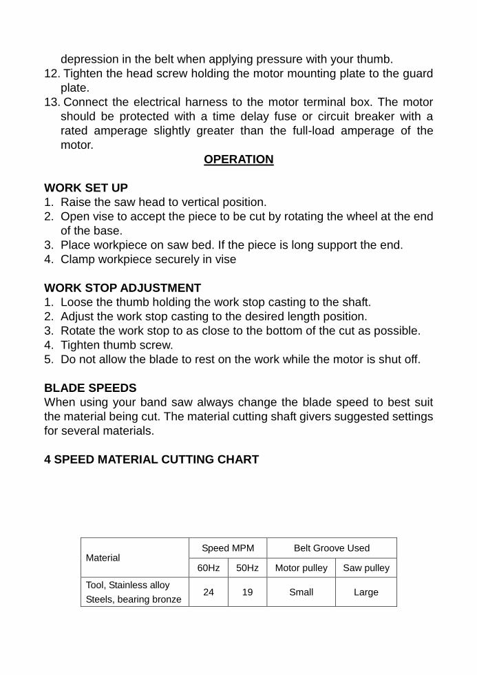
BLADE SPEEDS
When using your band saw always change the blade speed to best suit
the material being cut. The material cutting shaft givers suggested settings
for several materials.
4 SPEED MATERIAL CUTTING CHART
Material Speed MPM Belt Groove Used
60Hz 50Hz Motor pulley Saw pulley
Tool, Stainless alloy
Steels, bearing bronze 24 19 Small Large

Mild steel, hard brass
or bronze 36 28 Medium Medium
Aluminum plastic 60 50 Large Small
BLADE DIRECTION
OF TRAVEL
Be sure the blade is assembled to the pulleys such that the vertical edge
engages the work piece first.
STARTING SAW
Switch button function description (FOR CE ONLY)
CAUTION: NEVER OPERATE SAW WITHOUT BLADE GUARDS IN
PLACE.
Be sure the blade is not in contact with the work when the motor is started.
Start the motor, allow the saw to come to full speed, then begin the cut by
left the head down slowly onto the work. DO NOT DROP OR FOR. Let the
weight of the saw head provide the cutting force. The saw automatically
shuts off the end of the cut.
BLADE SELECTION
A 8-tooth per inch, general-use blade is furnished with this metal cutting
band saw. Additional blades in 4,6,8 and 10 tooth sizes are available. The
choice of the blade pitch is governed by the thickness of the work to be cut;
the thinner the workpiece, the more teeth advised. A minimum of three
teeth should engage the workpiece at all times for proper cutting. If the
teeth of the blade are so far apart that they straddle the work, severe
damage to the workpiece and to the blade can result.
CHANGING BLADE
Raise saw head to vertical position and open the blade guards. Loosen
tension screw knob sufficiently to allow the saw blade to slip off the wheels.
Install the new blade with teeth slanting toward the motor as follows:
1. Place the blade in between each of the guide bearings.
2. Slip the blade around the motor pulley (bottom) with the left hand and
hold in position.
3. Hold the blade taut against the motor pulley by pulling the blade
upward with the right hang which is placed at the top of the blade.
4. Remove left hand from bottom pulley and place it at the top aide of the
blade to continue the application on the upward pull on the blade.
5. Remove right hand from blade and adjust the position of the top pulley
to permit left hand to slip the blade around the pulley using the thumb
index and little finger as guides.
6. Adjust the blade tension knob clockwise until it is just right enough so
no blade slippage occurs. Do not tighten excessively.
7. Replace the blade guards.
8. Place 2-3 drops of oil on the blade.
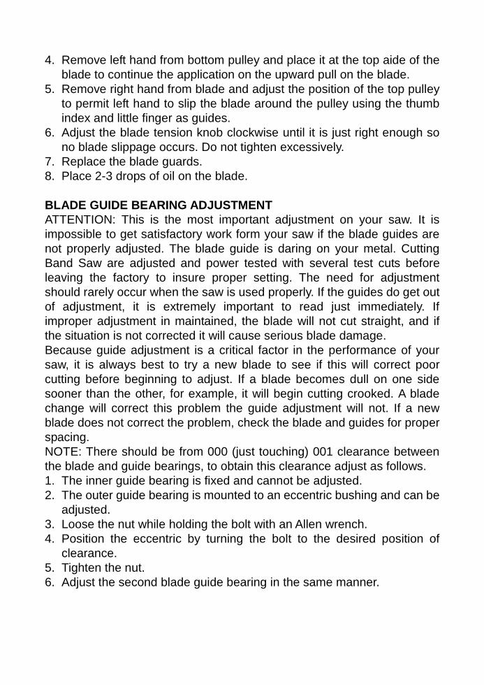
BLADE GUIDE BEARING ADJUSTMENT
ATTENTION: This is the most important adjustment on your saw. It is
impossible to get satisfactory work form your saw if the blade guides are
not properly adjusted. The blade guide is daring on your metal. Cutting
Band Saw are adjusted and power tested with several test cuts before
leaving the factory to insure proper setting. The need for adjustment
should rarely occur when the saw is used properly. If the guides do get out
of adjustment, it is extremely important to read just immediately. If
improper adjustment in maintained, the blade will not cut straight, and if
the situation is not corrected it will cause serious blade damage.
Because guide adjustment is a critical factor in the performance of your
saw, it is always best to try a new blade to see if this will correct poor
cutting before beginning to adjust. If a blade becomes dull on one side
sooner than the other, for example, it will begin cutting crooked. A blade
change will correct this problem the guide adjustment will not. If a new
blade does not correct the problem, check the blade and guides for proper
spacing.
NOTE: There should be from 000 (just touching) 001 clearance between
the blade and guide bearings, to obtain this clearance adjust as follows.
1. The inner guide bearing is fixed and cannot be adjusted.
2. The outer guide bearing is mounted to an eccentric bushing and can be
adjusted.
3. Loose the nut while holding the bolt with an Allen wrench.
4. Position the eccentric by turning the bolt to the desired position of
clearance.
5. Tighten the nut.
6. Adjust the second blade guide bearing in the same manner.

ADJUSTING BLADE TENSION
1. Make sure the motor is shut
off.
2. Press the blade lightly with
left hand, make the rear blade
against the flange of blade
wheel and test the blade
tension.
Adjusting Blade Tension
3. Adjust the blade tension adjustable knob with the
right hand until the blade obtain the proper tension.
ADJUSTING THE BLADE TRACKING
This adjusting has been completed and power-tested at the factory. The
need for adjusting should rarely occur when the saw is used properly. If
the tracking goes out of adjusting is listed below:
CUTTING
Close switch, letting the head down slowly onto the work, Do not drop or
force. Let the weight of the saw head provide the cutting force. The saw
automatically shuts off at end of the cut.
Method of adjusting blade:
A. Loosen the screw #11.
B. Adjust the blade adjustable seat #64 to make the blade vertical to bed.
C. Place the square on the bed to check if the blade is vertical, if not,
repeat the process A to C.
Step 1: Turn simultaneously with adjusting set screw to
make the blade track against the shoulder of the pulley.
To increase blade tension
Step 2: Loosen this hex.
Head screw-before turning
the adjusting set screw.
Step 4: Tighten after adjusting
Step 3: Turn simultaneously with
blade tension knob to make
blade track against shoulder of
pulley
Step 5: Adjust the blade
adjustable seat according to the
material size.
To relieve blade tension
The arrow indicates the moving direction
Step 6: Adjust guide assembly to
where the blade just touches the
back-up bearing.

D. Tighten the screw #11.
Adjusting the blade
MAINTENANCE CAUTION: MAKE CERTAIN THAT THE UNIT IS DISCONNECTED FROM THE
POWER SOURCE BEFORE ATTEMTING TO SERVICE OR REMOVE ANY
COMPONENT!
LUBRICATION
Lubricate the following components using SAE-30 oil as noted.
1. Ball-bearing none.
2. Driven pulley bearing 6-8 drops a week.
3. Vise lead screw as needed.
4. The drive gears run in an oil bath and will not required a lubricant
change more often than once a year, unless the lubricant is
accidentally contaminated or a leak occurs because of improper
replacement of the gear box cover. During the first few days of
operation, the worm gear drive will run hot. Unless the temperature
exceeds 200F, there is no cause for alarm.
The following lubricants may be used for the gear box:
Atlantic Refinery Co., Mogul Cyl. Oil
Cities Service Optimus No.6
Gulf Refinery Co Medium Gear Oil
Pure Oil co. Park Clipper

TROUBLE SHOOTING CHART
Symptom Possible Cause (s) Corrective Action
Excessive Blade
Breakage
1. Material loose in vise
2. Incorrect speed or feed
3. Blade teeth spacing too
large
4. Material too coarse
5. Incorrect blade tension
6. Teeth in contact with
material before saw is
started
7. Blade rubs on wheel
flange
8. Misaligned guide
bearings
9. Cracking at weld
1. Clamp work securely
2. Adjust speed or feed
3. Replace with a small teeth
spacing blade
4. Use a blade of slow speed
and small teeth spacing
5. Adjust where blade just
does not slip on wheel
6. Place blade in correct with
work after motor is started
7. Adjust wheel alignment
8. Adjust guide bearings
9. Weld again, note the weld
skill
Premature Blade
Dulling
1. Teeth too coarse
2. Too much speed
3. Inadequate feed pressure
4. Hard spots or scale on
material
5. Work hardening of
material
6. Blade twist
7. Insufficient blade
1. Use finer teeth
2. Decrease speed
3. Decrease spring tension
on side of saw
4. Reduce speed, in crease
feed pressure
5. Increase feed pressure by
reducing spring tension
6. Replace with a new blade,
and adjust blade tension
7. Tighten blade tension
adjustable knob
Unusual Wear on
Side/Back of Blade
1. Blade guides worn
2. Blade guide bearings not
adjusted properly
3. Blade guide bearing
bracket is loose
1. Replace
2. Adjust as per operators
manual
3. Tighten

Symptom Possible Cause (s) Corrective Action
Teeth Ripping from
Blade
1. Tooth too coarse for work
2. Too heavy pressure, too
slow speed
3. Vibrating work piece
4. Gullets loading
1. Use finer tooth blade
2. Decrease pressure,
increase speed
3. Clamp work piece
securely
4. Use coarse tooth blade or
brush to remove chips
Motor running too hot
1. Blade tension too high
2. Drive belt tension too high
3. Gears need lubrication
4. Cut is binding blade
5. Gears aligned improperly
1. Reduce tension on blade
2. Reduce tension on drive
belt
3. Check oil bath
4. Decrease feed and speed
5. Adjust gears so that worm
is in center of gear
Bad Cuts
1. Feed pressure too great
2. Guide bearing not
adjusted properly
3. Inadequate blade tension
4. Dull blade
5. Speed incorrect
6. Blade guide spaced out
too much
7. Blade guide assembly
loose
8. Blade truck too far away
from wheel flanges
1. Reduce pressure by
increasing spring tension
on side of saw
2. Adjust guide bearing, the
clearance can not be
greater than 0.001mm
3. Increase blade tension by
adjust blade tension
4. Replace blade
5. Adjust speed
6. Adjust guides space
7. Tighten
8. Re-track blade according
to operating instructions
Bad Cuts
(Rough)
1. Too much speed or feed
2. Blade is too coarse
3. Blade tension loose
1. Decrease speed or feed
2. Replace with finer blade
3. Adjust blade tension
Blade is twisting 1. Cut is binding blade
2. Too much blade tension
1. Decrease feed pressure
2. Decrease blade tension
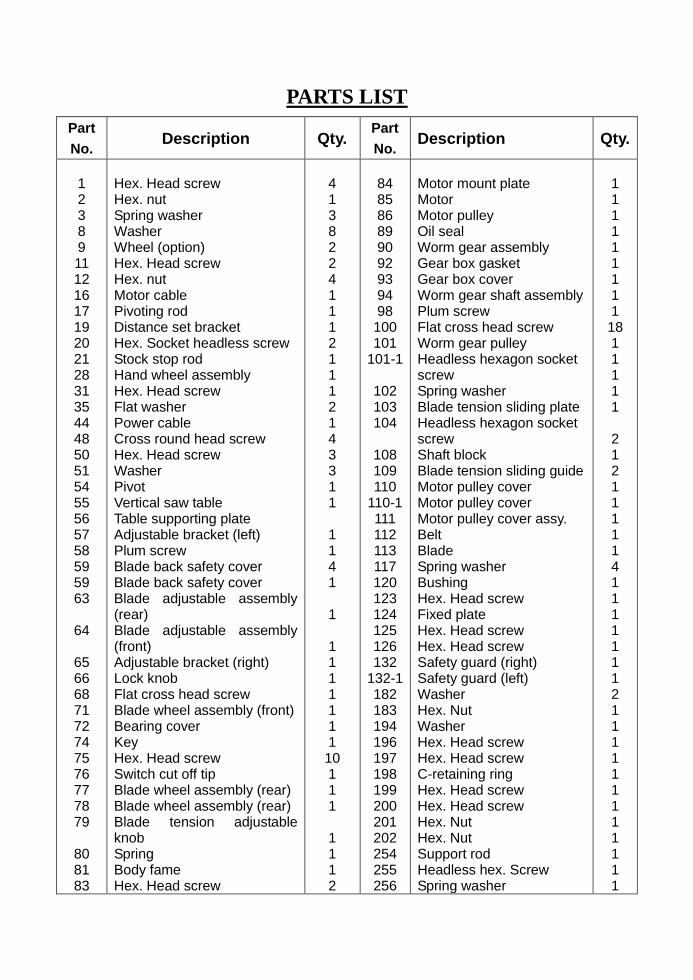
PARTS LIST
Part
No. Description Qty.
Part
No. Description Qty.
1 2 3 8 9 11 12 16 17 19 20 21 28 31 35 44 48 50 51 54 55 56 57 58 59 59 63
64
65 66 68 71 72 74 75 76 77 78 79
80 81 83
Hex. Head screw Hex. nut Spring washer Washer Wheel (option) Hex. Head screw Hex. nut Motor cable Pivoting rod Distance set bracket Hex. Socket headless screw Stock stop rod Hand wheel assembly Hex. Head screw Flat washer Power cable Cross round head screw Hex. Head screw Washer Pivot Vertical saw table Table supporting plate Adjustable bracket (left) Plum screw Blade back safety cover Blade back safety cover Blade adjustable assembly (rear) Blade adjustable assembly (front) Adjustable bracket (right) Lock knob Flat cross head screw Blade wheel assembly (front) Bearing cover Key Hex. Head screw Switch cut off tip Blade wheel assembly (rear) Blade wheel assembly (rear) Blade tension adjustable knob Spring Body fame Hex. Head screw
4 1 3 8 2 2 4 1 1 1 2 1 1 1 2 1 4 3 3 1 1
1 1 4 1
1
1 1 1 1 1 1 1 10 1 1 1
1 1 1 2
84 85 86 89 90 92 93 94 98 100 101
101-1
102 103 104
108 109 110
110-1 111 112 113 117 120 123 124 125 126 132
132-1 182 183 194 196 197 198 199 200 201 202 254 255 256
Motor mount plate Motor Motor pulley Oil seal Worm gear assembly Gear box gasket Gear box cover Worm gear shaft assembly Plum screw Flat cross head screw Worm gear pulley Headless hexagon socket screw Spring washer Blade tension sliding plate Headless hexagon socket screw Shaft block Blade tension sliding guide Motor pulley cover Motor pulley cover Motor pulley cover assy. Belt Blade Spring washer Bushing Hex. Head screw Fixed plate Hex. Head screw Hex. Head screw Safety guard (right) Safety guard (left) Washer Hex. Nut Washer Hex. Head screw Hex. Head screw C-retaining ring Hex. Head screw Hex. Head screw Hex. Nut Hex. Nut Support rod Headless hex. Screw Spring washer
1 1 1 1 1 1 1 1 1 18 1 1 1 1 1 2 1 2 1 1 1 1 1 4 1 1 1 1 1 1 1 2 1 1 1 1 1 1 1 1 1 1 1 1

257 258 259 261 262 263 300 301 302 303 304 305 306 307 308 309 310 311 312 313 314 315 316 317 318 319 320 321 322 323 324 325 326 327 328 329 330 331 332 333 334 338 339 340
Hex. Head screw Cylinder assembly Cylinder upper support Hex. Socket headless screw Hex. Head screw Spring washer Hex. Socket head screw Vise jaw bracket (rear) Vise jaw bracket (front) Wall plate Swivel base (upper) Bracket Acme nut Acme screw Bushing Flat washer Hexagon screw Hex. Head screw Flat screw Hexagon screw Hex. Socket headless screw Positioning ring Hex. Nut Flat washer Hexagon screw Hex. Nut Hex. Head screw Position pin Plum handle Screw Handle Carriage screw Screw Electrical box Switch base Cross round head screw On-off switch Screw Cable connector Cotter pin Protect plate Scale Hex. Head screw Flat washer
1 1 1 1 2 2 1 1 1 1 1 1 1 1 2 2 2 3 5 2 2 1 1 1 1 1 1 1 1 2 1 1 1 1 1 2 1 2 2 2 1 1 6 6
341 342 343 344 345 346 347 348 349 350 351 352 353 354 355 356 357 359 360 361 362 363 364 365 366 367 368 369 370 371 372 373 374 375 376 377 378
Hex. Nut Balancing bracket Flat washer Hexagon head screw Flat briquette Screw rod Balancing spring Leg Built-in shelf (option) Front plate Hex. Head screw Flat screw Hex. Nut Hex. Nut Flat washer Hexagon head screw Walking wheel set Stand complete assy. Wheel setting bracket Wheel rod Hex. Head screw Spring washer Hex. Nut Hex. Head screw Rubber head screw Spring washer Cross round head screw Knob w/shaft Knob Cotter pin Handle shaft stopper Screw plate Pivot pin Ball Ring Cross round head screw Chain
6 1 2 2 1 1 1 4 1 1 14 14 14 4 4 4 2 1 2 1 4 8 4 4 4 16 16 1 1 1 1 1 1 1 1 2 1