Embed Size (px)
Citation preview

CONTENTS
1. Specifications..........................................................................................................2
2. Outline and Dimensions....................................................................................... 4
3. Operation .............................................................................................................. 9
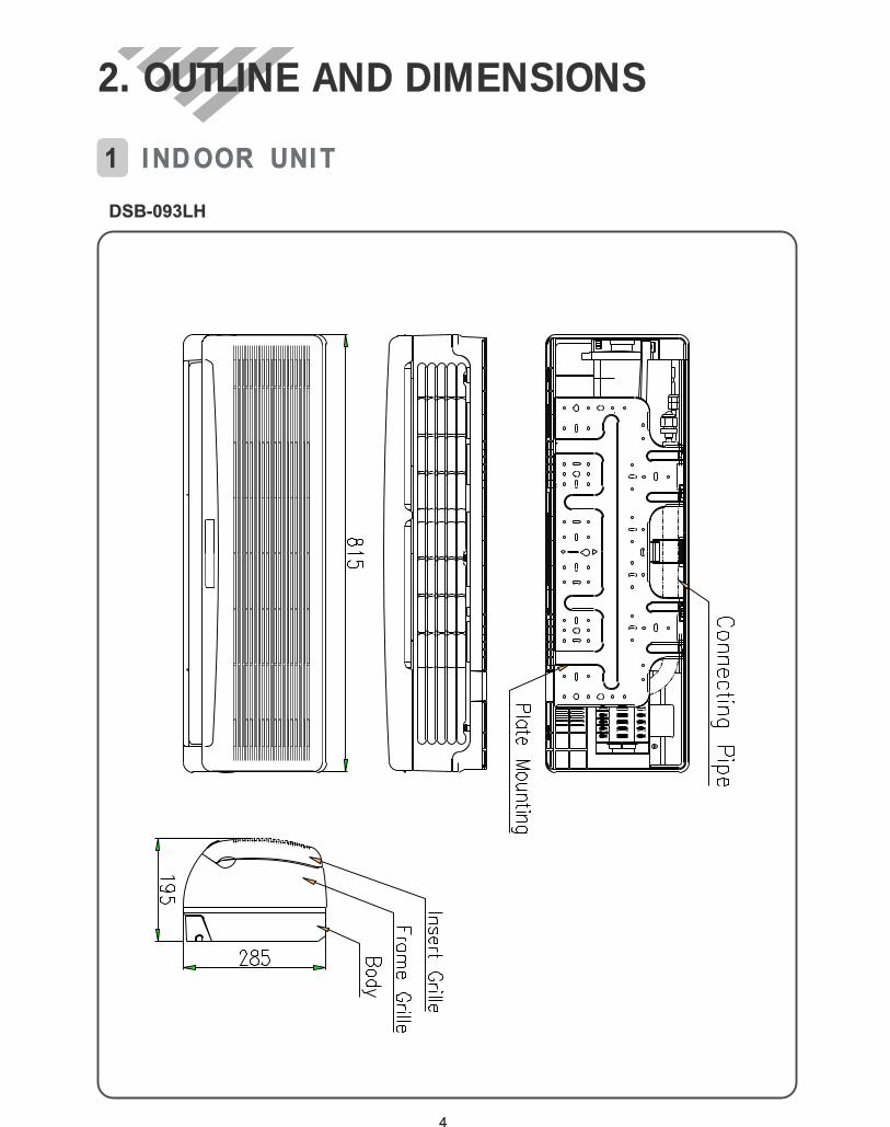
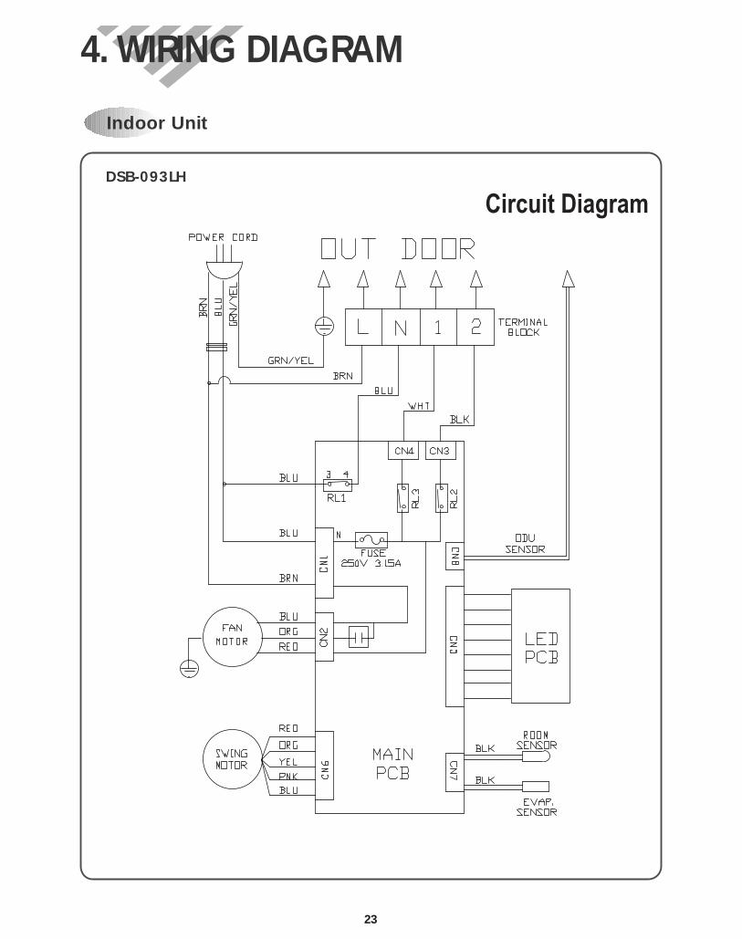
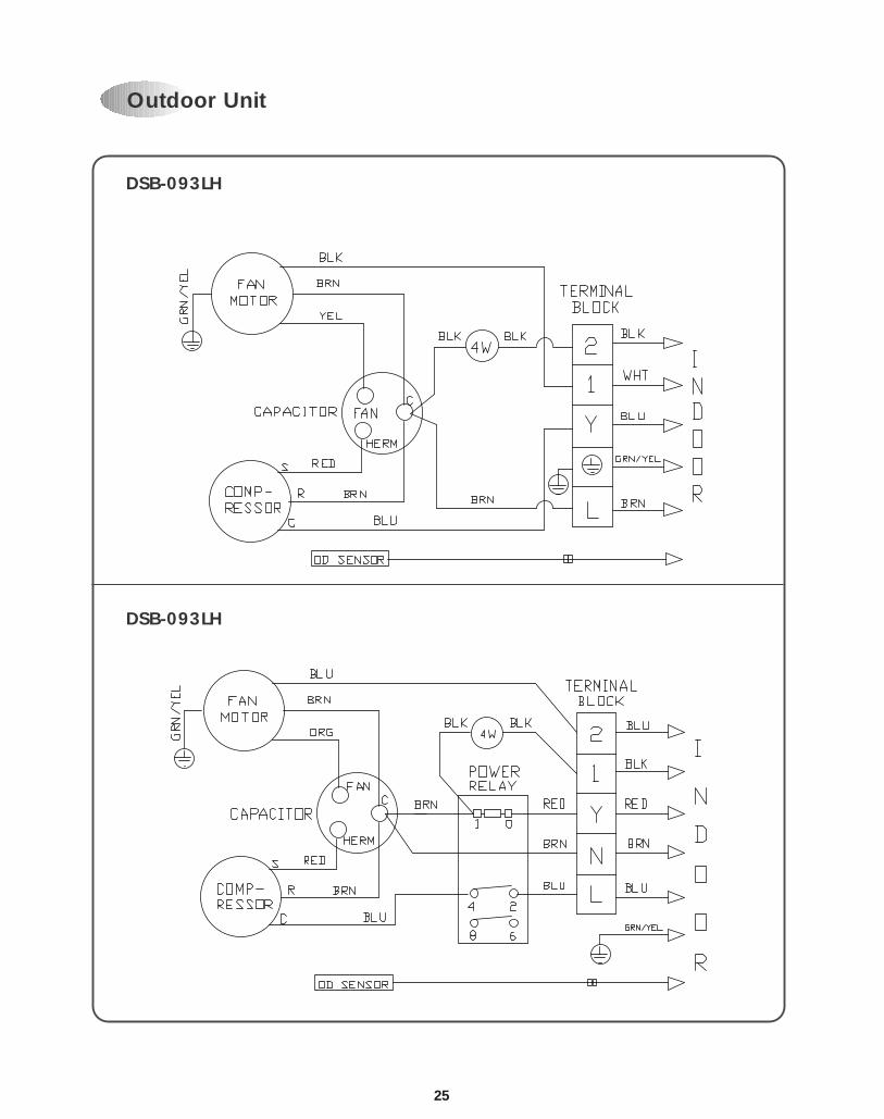
4. Wiring Diagram.....................................................................................................23
5. Refrigerant Cycle..................................................................................................27
6. Control Block Diagram .........................................................................................30
7. Trouble Shooting...................................................................................................32
8. Key Components of Electronic Circuit .................................................................54
9. Disassembly Instructions .....................................................................................57
1) Indoor Unit ........................................................................................................57
2) Outdoor Unit .....................................................................................................59
3) Exploded Diagram And Parts List (Indoor Unit)..............................................61
4) Exploded Diagram And Parts List (Outdoor Unit)...........................................65
5) Control Box Assembly And Parts List..............................................................71
Contents
2
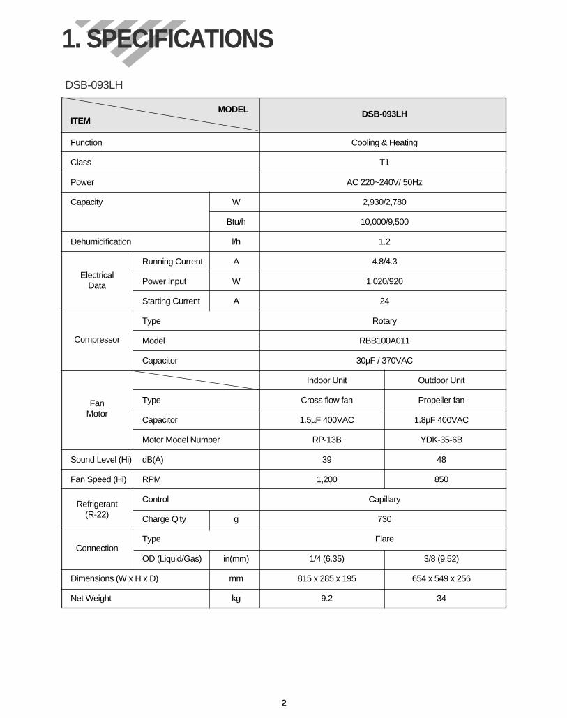
MODEL DSB-093LHITEM
Function Cooling & Heating
Class T1
Power AC 220~240V/ 50Hz
Capacity W 2,930/2,780
Btu/h 10,000/9,500
Dehumidification l/h 1.2
Running Current A 4.8/4.3
Power Input W 1,020/920
Starting Current A 24
Type Rotary
Model RBB100A011
Capacitor 30µF / 370VAC
Indoor Unit Outdoor Unit
Type Cross flow fan Propeller fan
Capacitor 1.5µF 400VAC 1.8µF 400VAC
Motor Model Number RP-13B YDK-35-6B
Sound Level (Hi) dB(A) 39 48
Fan Speed (Hi) RPM 1,200 850
Control Capillary
Charge Q'ty g 730
Type Flare
OD (Liquid/Gas) in(mm) 1/4 (6.35) 3/8 (9.52)
Dimensions (W x H x D) mm 815 x 285 x 195 654 x 549 x 256
Net Weight kg 9.2 34
Electrical Data
Compressor
FanMotor
Refrigerant(R-22)
Connection
DSB-093LH
1. SPECIFICATIONS
3
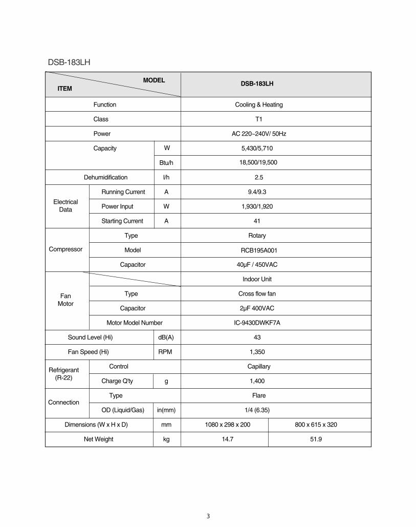
MODEL ITEM
Function
Class
Power
Capacity
Btu/h
Dehumidification l/h
Running Current A
Power Input W
Starting Current A
Type
Model
Capacitor
Type
Capacitor
Motor Model Number
Sound Level (Hi) dB(A)
Fan Speed (Hi) RPM
Control
Charge Q'ty g
Type
OD (Liquid/Gas) in(mm)
Dimensions (W x H x D) mm 1080 x 298 x 200 800 x 615 x 320
Net Weight kg 14.7 51.9
Electrical Data
Compressor
FanMotor
Refrigerant(R-22)
Connection
DSB-183LH
W
DSB-183LH
Cooling & Heating
T1
AC 220~240V/ 50Hz
5,430/5,710
2.5
9.4/9.3
1,930/1,920
41
Rotary
40µF / 450VAC
Indoor Unit
Cross flow fan
2µF 400VAC
IC-9430DWKF7A
43
1,350
Capillary
1,400
Flare
1/4 (6.35)
18,500/19,500
RCB195A001

5
Connecting P
ipe
Body
Frame G
rille
Grille Insert
Plate M
ounting430
710
1080
Filter-L
Filter-R
RE
MO
CO
N
DSB-183LH
200
298
6
Indoor Unit
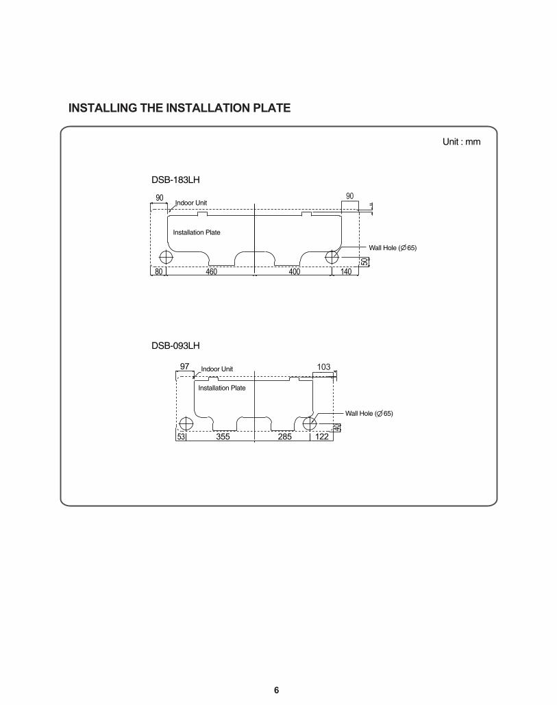
DSB-183LH
DSB-093LH
Indoor Unit
Installation Plate
Wall Hole ( 65)
Wall Hole ( 65)
Installation Plate
90
97
53 355 285 122
40
80 460 400 140
50
Unit : mm
INSTALLING THE INSTALLATION PLATE
103
90
7
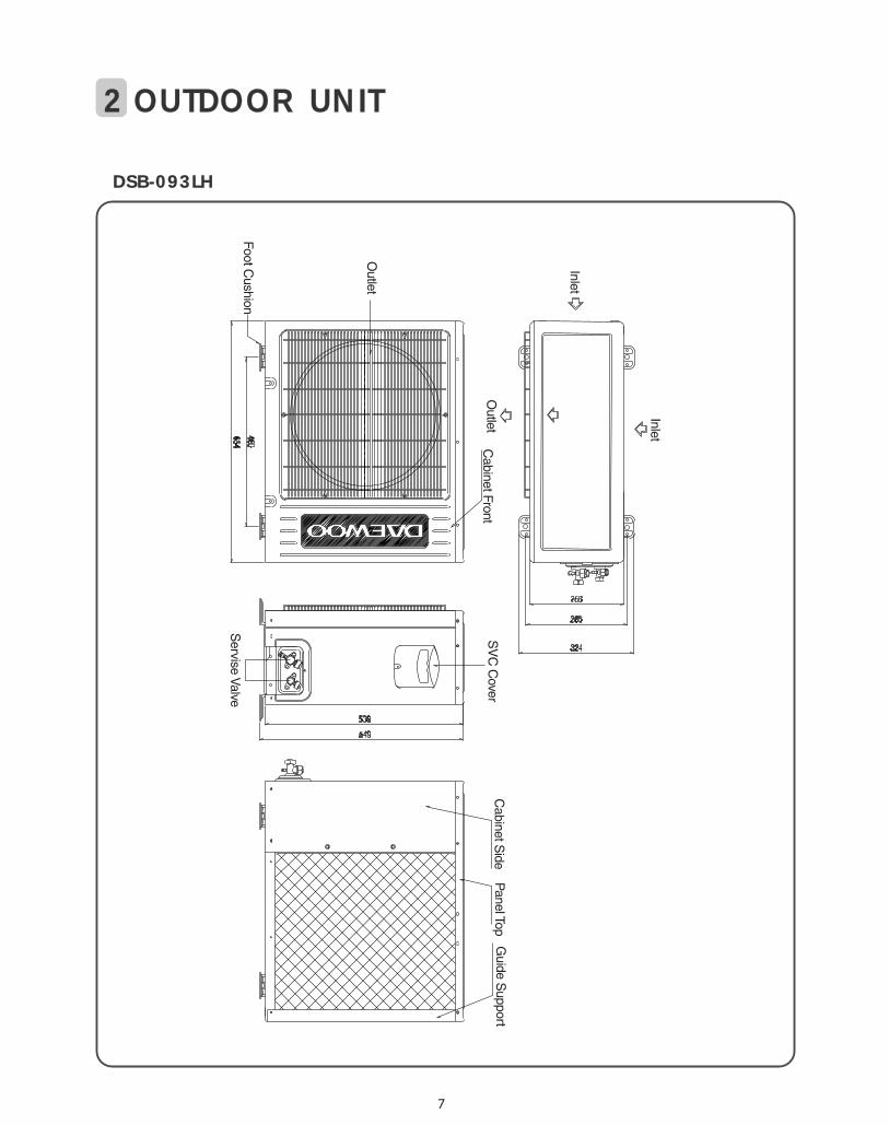
DSB-093LH
Outlet
Foot Cushion
Cabinet Front
Cabinet S
ideP
anel TopG
uide Support
SV
C C
over
Servise Valve
Inlet
Outlet
Inlet
2 OUTDOOR UNIT
8
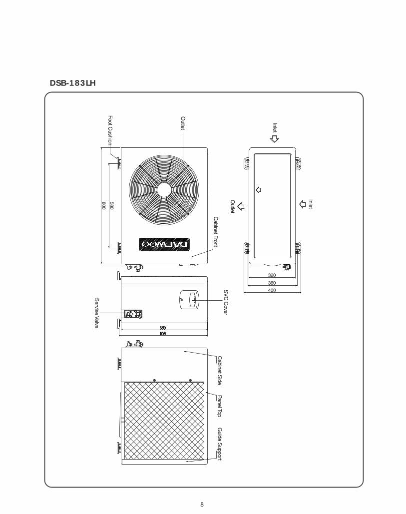
DSB-183LHInlet
Outlet
Outlet
Foot Cushion
Cabinet Front
Cabinet S
ideP
anel TopG
uide Support
SV
C C
over
Servise Valve
580
800
320
360
400
Inlet
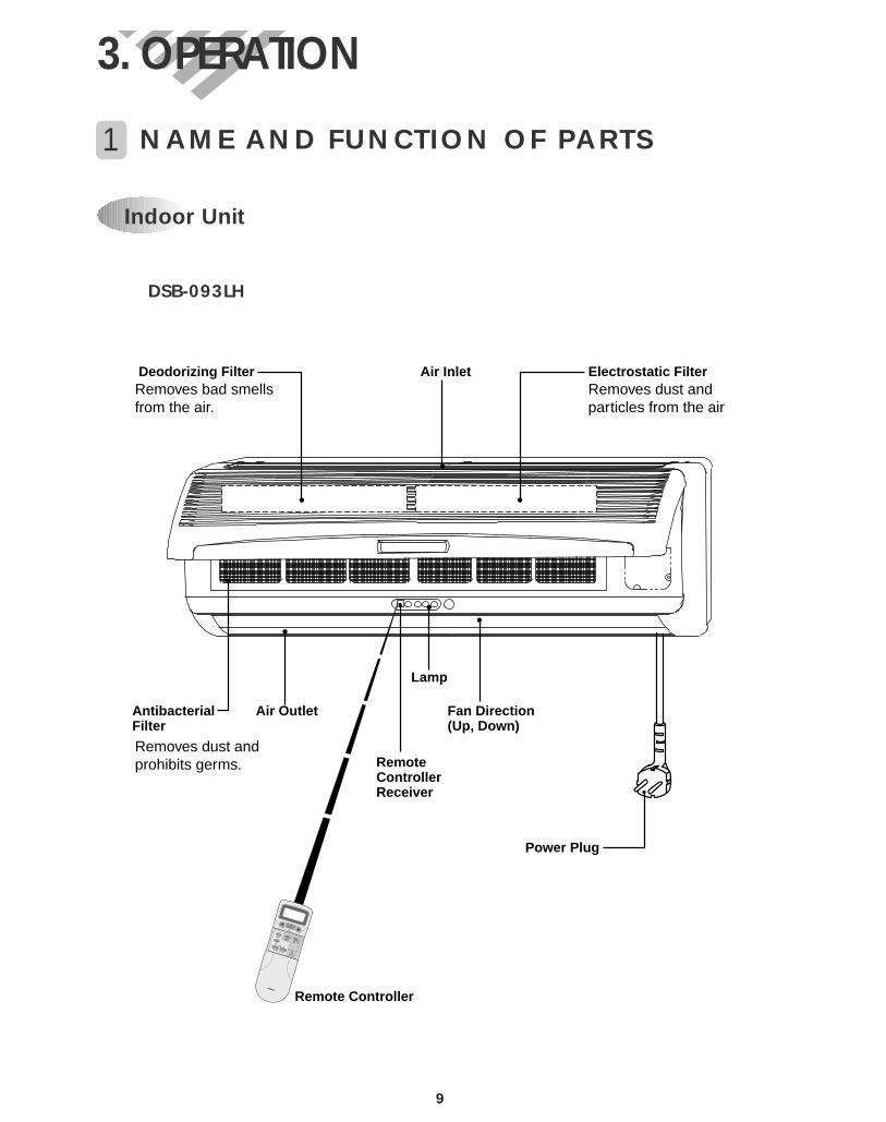
1 NAME AND FUNCTION OF PARTS
Indoor Unit
3. OPERATION
DSB-093LH
Power Plug
Electrostatic FilterDeodorizing Filter Air Inlet
AntibacterialFilter
Air Outlet Fan Direction(Up, Down)
Remote Controller
RemoteControllerReceiver
Lamp
Removes bad smellsfrom the air.
Removes dust andprohibits germs.
Removes dust andparticles from the air
9
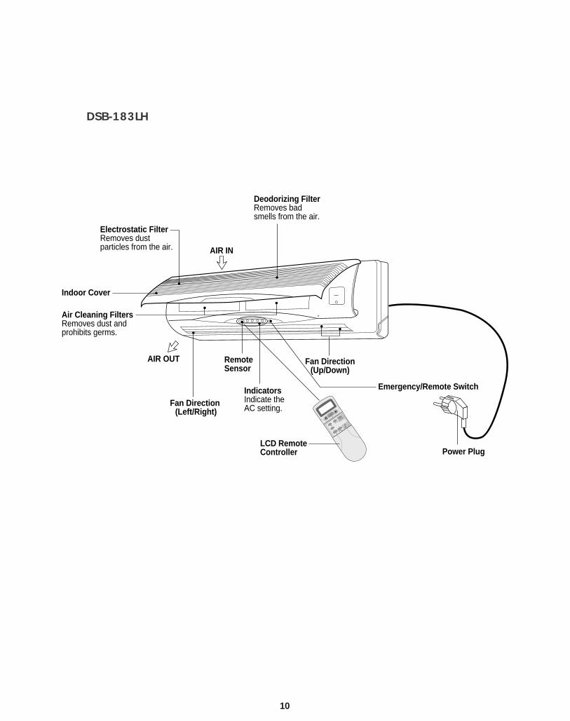
10
Indoor Cover
Electrostatic FilterRemoves dust particles from the air.
Deodorizing FilterRemoves badsmells from the air.
Emergency/Remote SwitchIndicatorsIndicate theAC setting.
RemoteSensor
Power PlugLCD RemoteController
Air Cleaning FiltersRemoves dust and prohibits germs.
AIR OUT
AIR IN
Fan Direction(Up/Down)
Fan Direction (Left/Right)
DE
L
N O
ENER
N
E
N SE
D
URBOD
AN D R
DSB-183LH
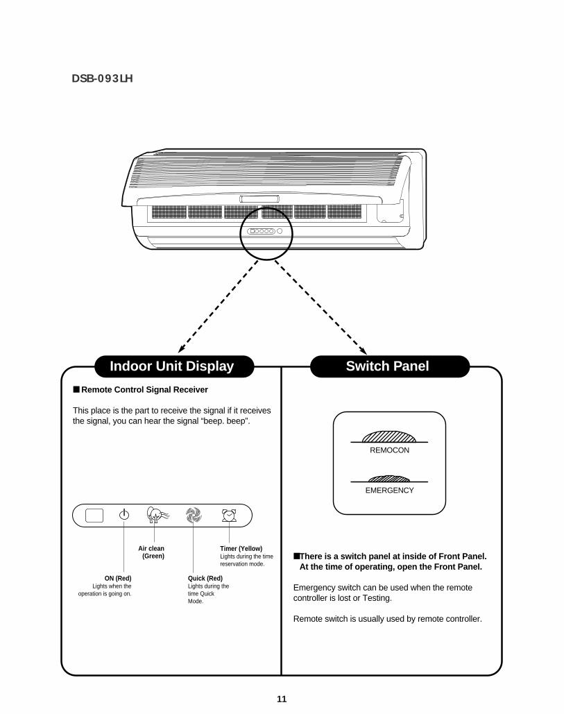
DSB-093LH
Remote Control Signal Receiver
This place is the part to receive the signal if it receivesthe signal, you can hear the signal “beep. beep”.
There is a switch panel at inside of Front Panel.At the time of operating, open the Front Panel.
Emergency switch can be used when the remotecontroller is lost or Testing.
Remote switch is usually used by remote controller.
Indoor Unit Display Switch Panel
11
ON (Red)Lights when the
operation is going on.
Air clean(Green)
Timer (Yellow)Lights during the timereservation mode.
Quick (Red)Lights during thetime QuickMode.
REMOCON
EMERGENCY
12
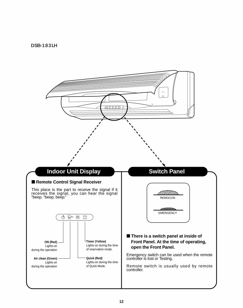
DSB-183LH
Remote Control Signal Receiver
This place is the part to receive the signal if itreceives the signal, you can hear the signal“beep. “beep, beep.”
There is a switch panel at inside ofFront Panel. At the time of operating,open the Front Panel.
Emergency switch can be used when the remotecontroller is lost or Testing.
Remote switch is usually used by remotecontroller.
Indoor Unit Display Switch Panel
Timer (Yellow)Lights-on during the timeof reservation mode.
Quick (Red)Lights-on during the timeof Quick Mode.
ON (Red)Lights-on
during the operation
Air clean (Green)Lights-on
during the operation
REMOCON
EMERGENCY
13
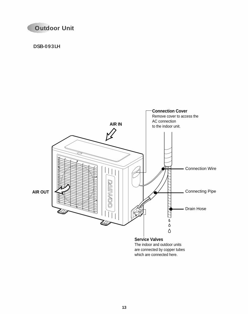
DSB-093LH
Connection CoverRemove cover to access the AC connectionto the indoor unit.
Service ValvesThe indoor and outdoor unitsare connected by copper tubeswhich are connected here.
AIR IN
AIR OUT
Connection Wire
Connecting Pipe
Drain Hose
Outdoor Unit
14
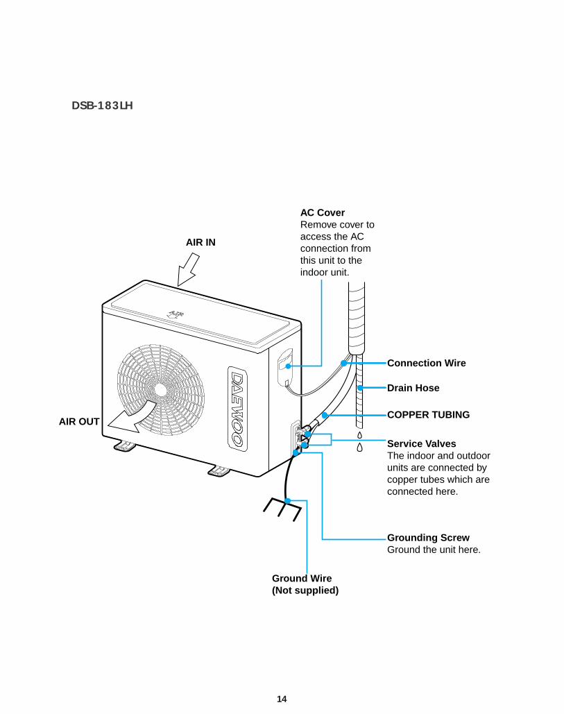
DSB-183LH
AIR IN
AIR OUT
AC CoverRemove cover toaccess the ACconnection fromthis unit to theindoor unit.
Connection Wire
Drain Hose
COPPER TUBING
Service ValvesThe indoor and outdoorunits are connected bycopper tubes which areconnected here.
Grounding ScrewGround the unit here.
Ground Wire(Not supplied)
15
MODE
SLEEP
ON/OFF
TIMER
ENTER/ CANCEL
FAN SPEED
TURBO/MILD
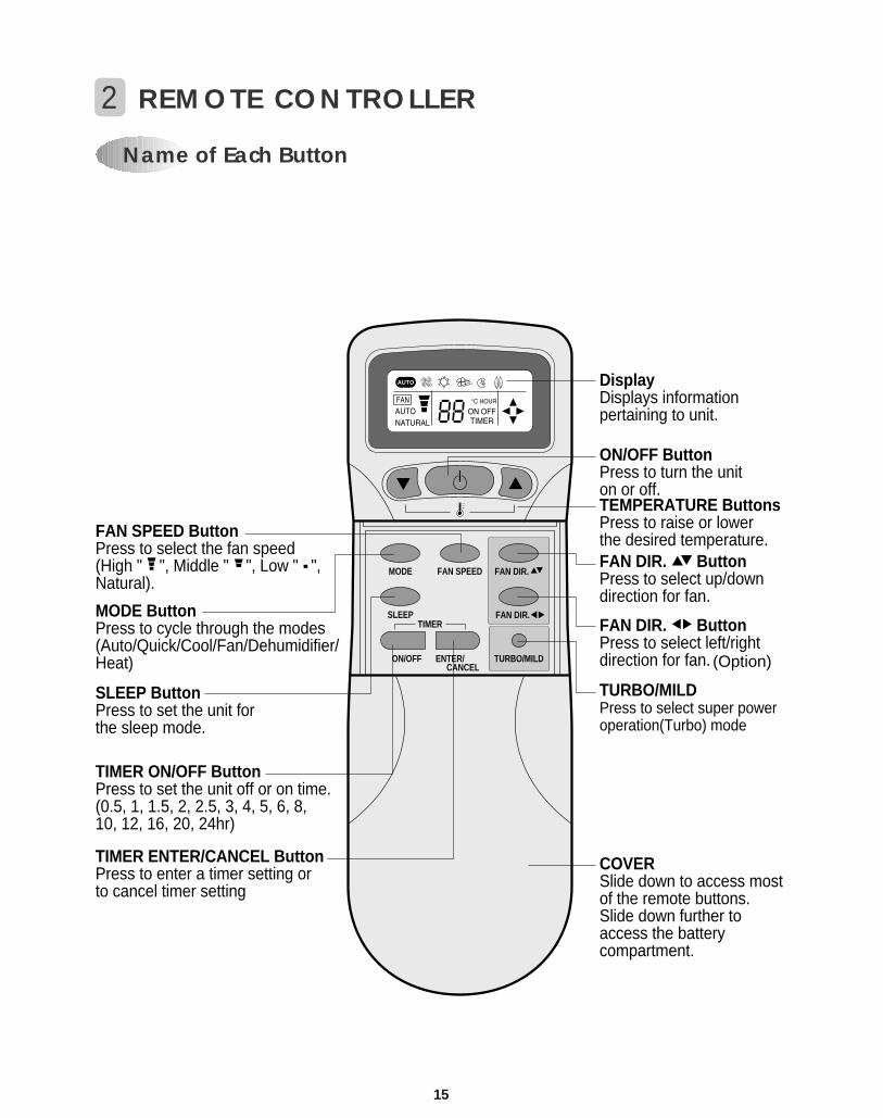
DisplayDisplays informationpertaining to unit.
TURBO/MILDPress to select super poweroperation(Turbo) mode
TIMER ENTER/CANCEL ButtonPress to enter a timer setting or to cancel timer setting
TIMER ON/OFF ButtonPress to set the unit off or on time.(0.5, 1, 1.5, 2, 2.5, 3, 4, 5, 6, 8, 10, 12, 16, 20, 24hr)
MODE ButtonPress to cycle through the modes(Auto/Quick/Cool/Fan/Dehumidifier/Heat)
SLEEP ButtonPress to set the unit forthe sleep mode.
FAN DIR. ButtonPress to select up/downdirection for fan.
FAN DIR. ButtonPress to select left/rightdirection for fan.
ON/OFF ButtonPress to turn the uniton or off.TEMPERATURE ButtonsPress to raise or lower the desired temperature.FAN SPEED Button
Press to select the fan speed (High " ", Middle " ", Low " ",Natural).
COVERSlide down to access mostof the remote buttons.Slide down further toaccess the batterycompartment.
AUTO
FAN DIR.
FAN DIR.
Name of Each Button
2 REMOTE CONTROLLER
(Option)
16
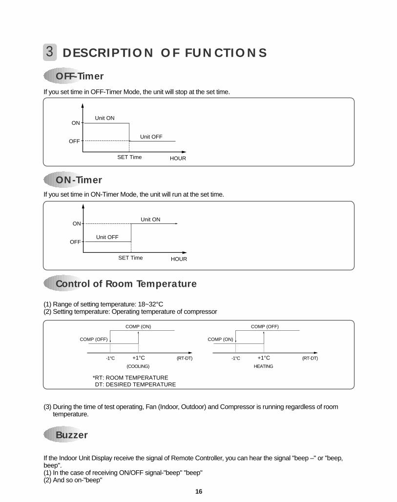
If you set time in OFF-Timer Mode, the unit will stop at the set time.
If you set time in ON-Timer Mode, the unit will run at the set time.
(1) Range of setting temperature: 18~32°C(2) Setting temperature: Operating temperature of compressor
(3) During the time of test operating, Fan (Indoor, Outdoor) and Compressor is running regardless of roomtemperature.
If the Indoor Unit Display receive the signal of Remote Controller, you can hear the signal "beep –" or "beep,beep".(1) In the case of receiving ON/OFF signal-"beep" "beep"(2) And so on-"beep"
OFF-Timer
3 DESCRIPTION OF FUNCTIONS
Unit ON
Unit OFF
SET Time HOUR
ON
OFF
ON-Timer
Unit ON
Unit OFF
SET Time HOUR
ON
OFF
Control of Room Temperature
Buzzer
COMP (ON)
*RT: ROOM TEMPERATURE DT: DESIRED TEMPERATURE
COMP (OFF)
-1°C
(COOLING)
(RT-DT)
COMP (OFF)
COMP (ON)
-1°C
HEATING
(RT-DT)+1°C +1°C
17
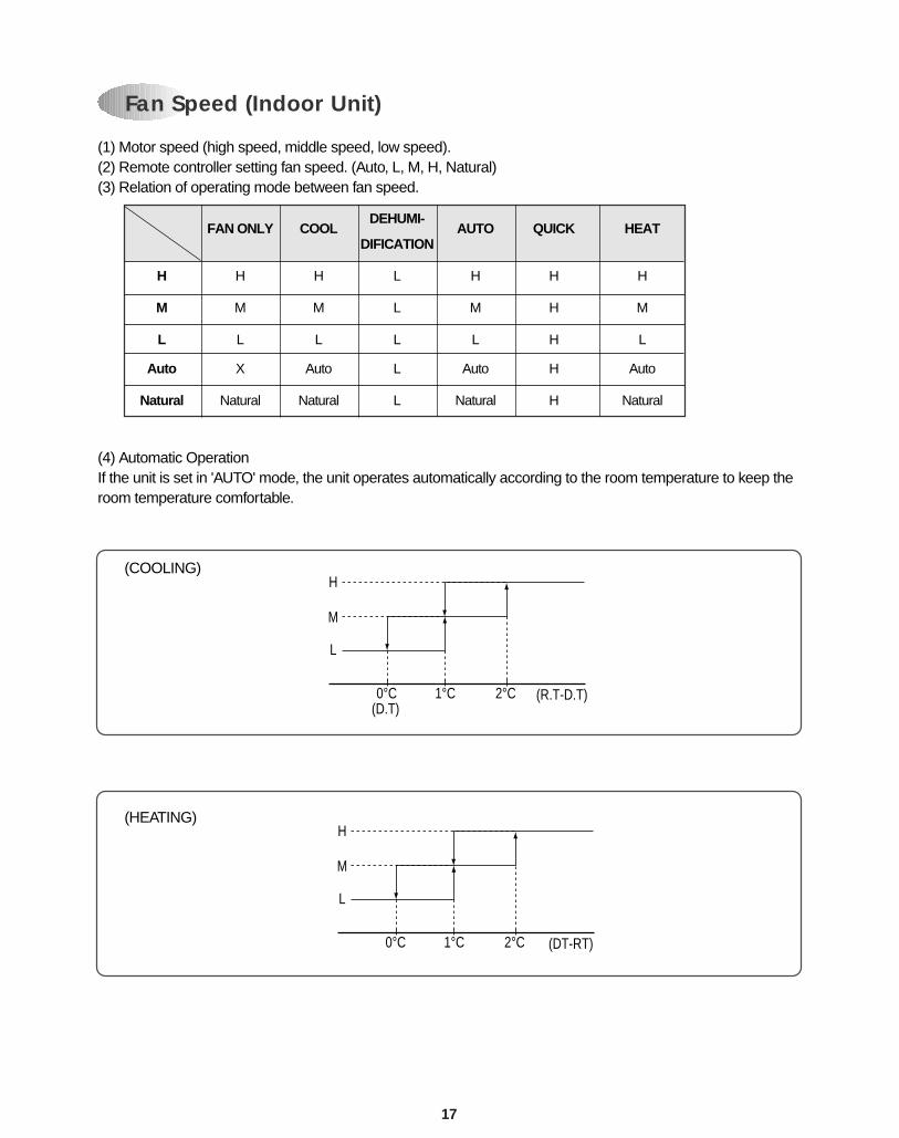
Fan Speed (Indoor Unit)
(1) Motor speed (high speed, middle speed, low speed).(2) Remote controller setting fan speed. (Auto, L, M, H, Natural)(3) Relation of operating mode between fan speed.
(4) Automatic OperationIf the unit is set in 'AUTO' mode, the unit operates automatically according to the room temperature to keep theroom temperature comfortable.
0°C
L
M
H
1°C 2°C (R.T-D.T)(D.T)
0°C
L
M
H
1°C 2°C (DT-RT)
(COOLING)
(HEATING)
FAN ONLY COOLDEHUMI-
AUTO QUICK HEATDIFICATION
H H H L H H H
M M M L M H M
L L L L L H L
Auto X Auto L Auto H Auto
Natural Natural Natural L Natural H Natural
18
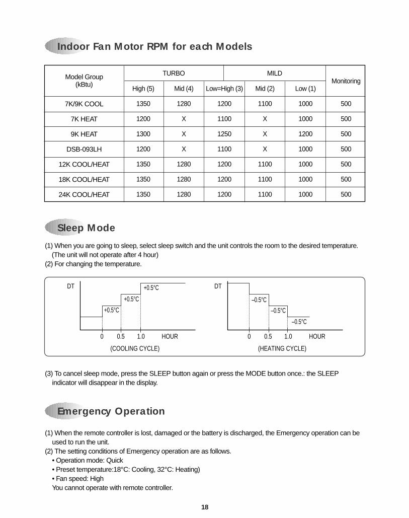
(1) When the remote controller is lost, damaged or the battery is discharged, the Emergency operation can beused to run the unit.
(2) The setting conditions of Emergency operation are as follows.• Operation mode: Quick• Preset temperature:18°C: Cooling, 32°C: Heating)• Fan speed: HighYou cannot operate with remote controller.
(1) When you are going to sleep, select sleep switch and the unit controls the room to the desired temperature. (The unit will not operate after 4 hour)
(2) For changing the temperature.
(3) To cancel sleep mode, press the SLEEP button again or press the MODE button once.: the SLEEPindicator will disappear in the display.
Sleep Mode
Indoor Fan Motor RPM for each Models
Emergency Operation
0 0.5 1.0 HOUR
(COOLING CYCLE)
DT
+0.5°C+0.5°C
+0.5°C
0 0.5 1.0 HOUR
(HEATING CYCLE)
DT
–0.5°C–0.5°C
–0.5°C
Model Group(kBtu)
7K/9K COOL
7K HEAT
9K HEAT
DSB-093LH
12K COOL/HEAT
18K COOL/HEAT
24K COOL/HEAT
High (5)
1350
1200
1300
1200
1350
1350
1350
Mid (4)
1280
X
X
X
1280
1280
1280
Low=High (3)
1200
1100
1250
1100
1200
1200
1200
Mid (2)
1100
X
X
X
1100
1100
1100
Low (1)
1000
1000
1200
1000
1000
1000
1000
Monitoring
500
500
500
500
500
500
500
TURBO MILD
19
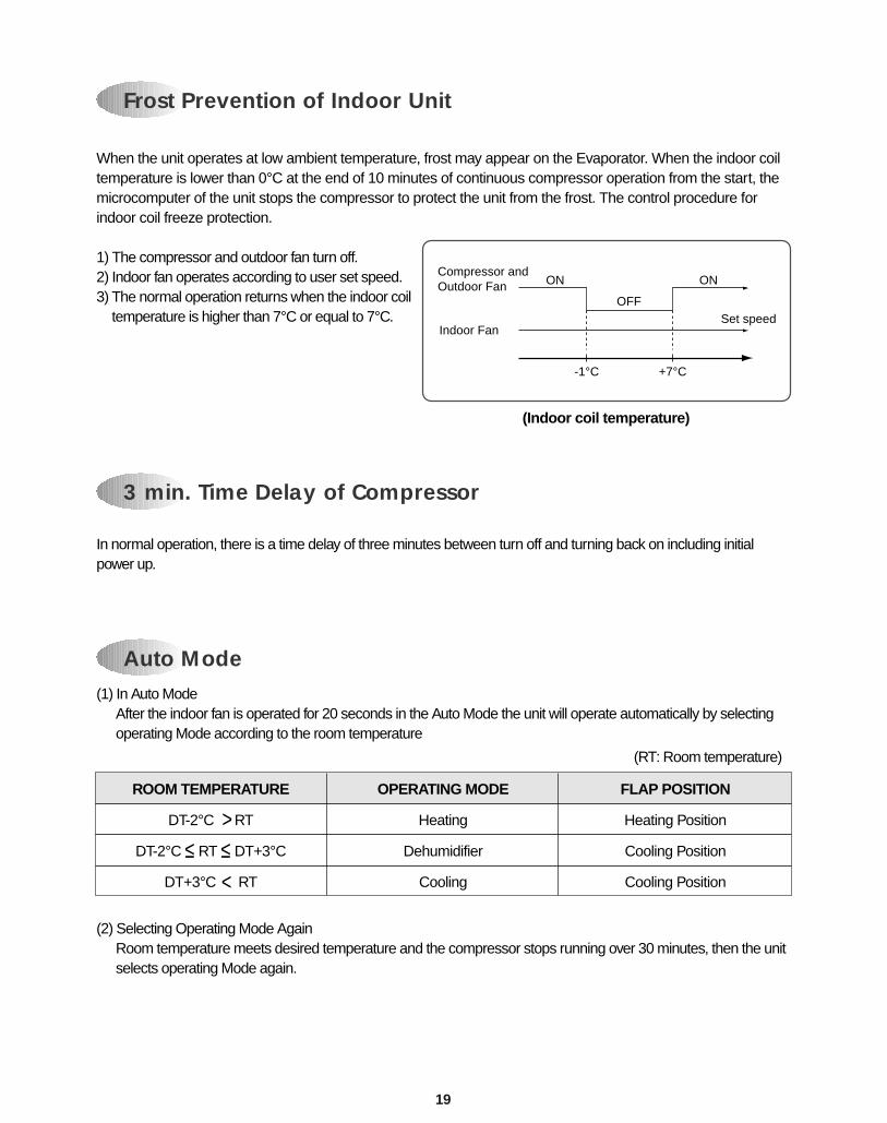
Frost Prevention of Indoor Unit
When the unit operates at low ambient temperature, frost may appear on the Evaporator. When the indoor coiltemperature is lower than 0°C at the end of 10 minutes of continuous compressor operation from the start, themicrocomputer of the unit stops the compressor to protect the unit from the frost. The control procedure forindoor coil freeze protection.
1) The compressor and outdoor fan turn off.2) Indoor fan operates according to user set speed.3) The normal operation returns when the indoor coil
temperature is higher than 7°C or equal to 7°C.
-1°C +7°C
Compressor and Outdoor Fan ON ON
OFF
Indoor FanSet speed
(Indoor coil temperature)
Auto Mode(1) In Auto Mode
After the indoor fan is operated for 20 seconds in the Auto Mode the unit will operate automatically by selectingoperating Mode according to the room temperature
(2) Selecting Operating Mode AgainRoom temperature meets desired temperature and the compressor stops running over 30 minutes, then the unitselects operating Mode again.
3 min. Time Delay of Compressor
In normal operation, there is a time delay of three minutes between turn off and turning back on including initialpower up.
ROOM TEMPERATURE
DT-2°C RT
DT-2°C ≤ RT ≤ DT+3°C
DT+3°C RT
OPERATING MODE
Heating
Dehumidifier
Cooling
FLAP POSITION
Heating Position
Cooling Position
Cooling Position
(RT: Room temperature)
>
<
20
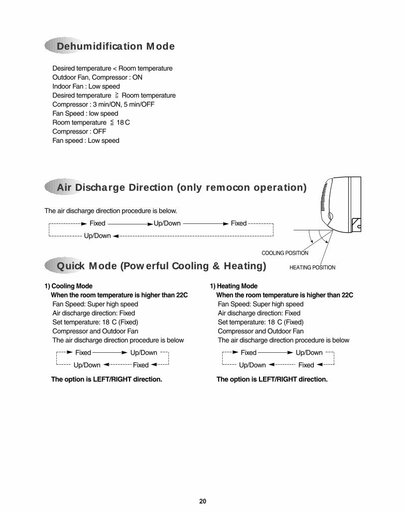
1) Cooling ModeWhen the room temperature is higher than 22CFan Speed: Super high speedAir discharge direction: Fixed
Set temperature: 18 C (Fixed) Compressor and Outdoor Fan
The air discharge direction procedure is below
Fixed Up/Down
Up/Down Fixed
The option is LEFT/RIGHT direction.
1) Heating ModeWhen the room temperature is higher than 22CFan Speed: Super high speedAir discharge direction: Fixed
Set temperature: 18 C (Fixed) Compressor and Outdoor Fan
The air discharge direction procedure is below
Fixed Up/Down
Up/Down Fixed
The option is LEFT/RIGHT direction.
Dehumidification Mode
Air Discharge Direction (only remocon operation)
Quick Mode (Powerful Cooling & Heating)
The air discharge direction procedure is below.
Fixed Up/Down Fixed
Up/Down
Desired temperature < Room temperatureOutdoor Fan, Compressor : ONIndoor Fan : Low speed Desired temperature Room temperatureCompressor : 3 min/ON, 5 min/OFFFan Speed : low speed
Room temperature 18 CCompressor : OFFFan speed : Low speed
COOLING POSITION
HEATING POSITION
>=
<=
21
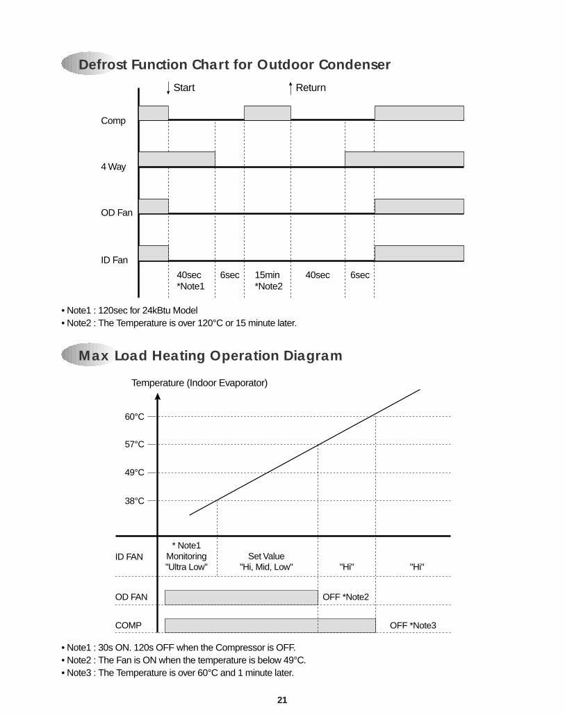
Defrost Function Chart for Outdoor Condenser
Max Load Heating Operation Diagram
• Note1 : 120sec for 24kBtu Model• Note2 : The Temperature is over 120°C or 15 minute later.
• Note1 : 30s ON. 120s OFF when the Compressor is OFF.• Note2 : The Fan is ON when the temperature is below 49°C.• Note3 : The Temperature is over 60°C and 1 minute later.
Comp
Start
4 Way
OD Fan
ID Fan
40sec*Note1
15min*Note2
6sec 6sec40sec
Return
60°C
Temperature (Indoor Evaporator)
57°C
49°C
38°C
ID FAN* Note1
Monitoring"Ultra Low"
Set Value"Hi, Mid, Low" "Hi" "Hi"
OD FAN OFF *Note2
OFF *Note3COMP
22
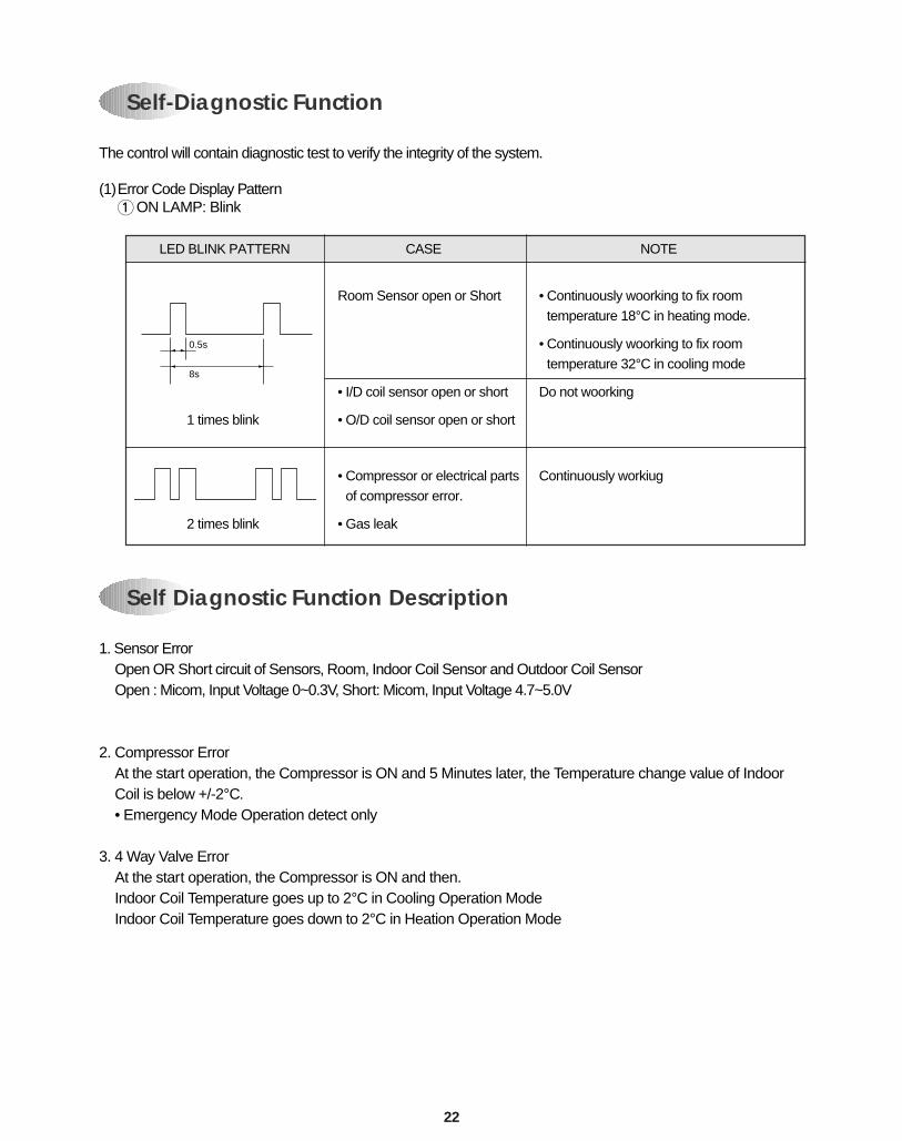
Self-Diagnostic Function
The control will contain diagnostic test to verify the integrity of the system.
(1)Error Code Display Pattern1ON LAMP: Blink
Self Diagnostic Function Description
1. Sensor ErrorOpen OR Short circuit of Sensors, Room, Indoor Coil Sensor and Outdoor Coil SensorOpen : Micom, Input Voltage 0~0.3V, Short: Micom, Input Voltage 4.7~5.0V
2. Compressor ErrorAt the start operation, the Compressor is ON and 5 Minutes later, the Temperature change value of IndoorCoil is below +/-2°C.• Emergency Mode Operation detect only
3. 4 Way Valve ErrorAt the start operation, the Compressor is ON and then.Indoor Coil Temperature goes up to 2°C in Cooling Operation ModeIndoor Coil Temperature goes down to 2°C in Heation Operation Mode
LED BLINK PATTERN CASE NOTE
Room Sensor open or Short • Continuously woorking to fix room
temperature 18°C in heating mode.
• Continuously woorking to fix room
temperature 32°C in cooling mode
• I/D coil sensor open or short Do not woorking
1 times blink • O/D coil sensor open or short
• Compressor or electrical parts Continuously workiug
of compressor error.
2 times blink • Gas leak
0.5s
8s
26
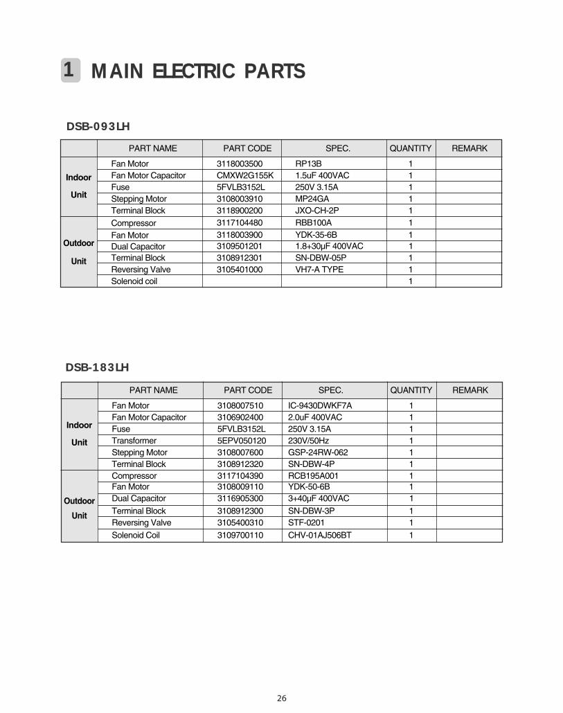
1 MAIN ELECTRIC PARTS
DSB-093LH
PART NAME PART CODE SPEC. QUANTITY REMARK
Fan Motor 3118003500 RP13B 1Fan Motor Capacitor CMXW2G155K 1.5uF 400VAC 1Fuse 5FVLB3152L 250V 3.15A 1Stepping Motor 3108003910 MP24GA 1Terminal Block 3118900200 JXO-CH-2P 1
Compressor 3117104480 RBB100A 1
Fan Motor 3118003900 YDK-35-6B 1Dual Capacitor 3109501201 1.8+30µF 400VAC 1Terminal Block 3108912301 SN-DBW-05P 1Reversing Valve 3105401000 VH7-A TYPE 1Solenoid coil 1
Outdoor
Unit
Indoor
Unit
DSB-183LH
PART NAME PART CODE SPEC. QUANTITY REMARK
Fan Motor 3108007510 IC-9430DWKF7A 1Fan Motor Capacitor 3106902400 2.0uF 400VAC 1Fuse 5FVLB3152L 250V 3.15A 1Transformer 5EPV050120 230V/50Hz 1Stepping Motor 3108007600 GSP-24RW-062 1Terminal Block 3108912320 SN-DBW-4P 1Compressor 3117104390 RCB195A001 1Fan Motor 3108009110 YDK-50-6B 1Dual Capacitor 3116905300 3+40µF 400VAC 1
Terminal Block 3108912300 SN-DBW-3P 1Reversing Valve 3105400310 STF-0201 1
Solenoid Coil 3109700110 CHV-01AJ506BT 1
Outdoor
Unit
Indoor
Unit
27
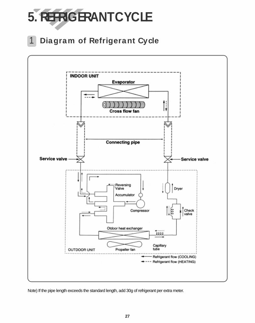
5. REFRIGERANT CYCLE
Note) If the pipe length exceeds the standard length, add 30g of refrigerant per extra meter.
1 Diagram of Refrigerant Cycle
28
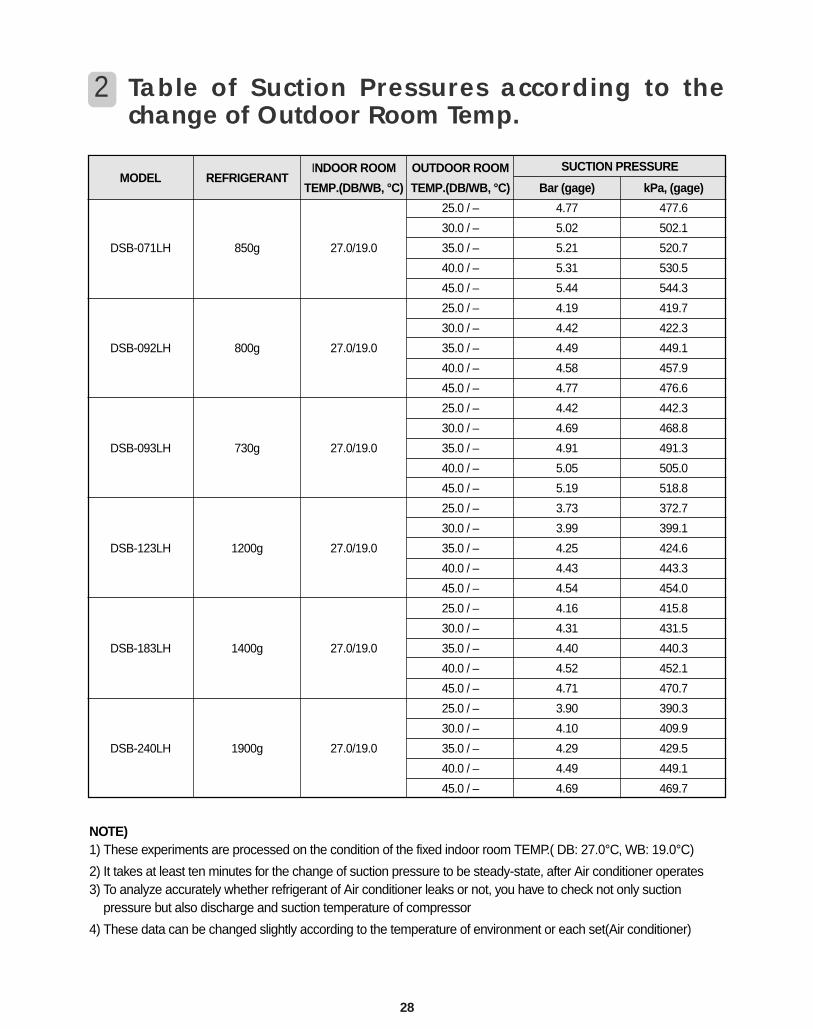
2 Table of Suction Pressures according to thechange of Outdoor Room Temp.
MODEL
DSB-071LH
DSB-092LH
DSB-093LH
DSB-123LH
DSB-183LH
DSB-240LH
REFRIGERANT
850g
800g
730g
1200g
1400g
1900g
INDOOR ROOM
TEMP.(DB/WB, °C)
27.0/19.0
27.0/19.0
27.0/19.0
27.0/19.0
27.0/19.0
27.0/19.0
OUTDOOR ROOM
TEMP.(DB/WB, °C)
25.0 / –
30.0 / –
35.0 / –
40.0 / –
45.0 / –
25.0 / –
30.0 / –
35.0 / –
40.0 / –
45.0 / –
25.0 / –
30.0 / –
35.0 / –
40.0 / –
45.0 / –
25.0 / –
30.0 / –
35.0 / –
40.0 / –
45.0 / –
25.0 / –
30.0 / –
35.0 / –
40.0 / –
45.0 / –
25.0 / –
30.0 / –
35.0 / –
40.0 / –
45.0 / –
Bar (gage)
4.77
5.02
5.21
5.31
5.44
4.19
4.42
4.49
4.58
4.77
4.42
4.69
4.91
5.05
5.19
3.73
3.99
4.25
4.43
4.54
4.16
4.31
4.40
4.52
4.71
3.90
4.10
4.29
4.49
4.69
kPa, (gage)
477.6
502.1
520.7
530.5
544.3
419.7
422.3
449.1
457.9
476.6
442.3
468.8
491.3
505.0
518.8
372.7
399.1
424.6
443.3
454.0
415.8
431.5
440.3
452.1
470.7
390.3
409.9
429.5
449.1
469.7
SUCTION PRESSURE
NOTE)1) These experiments are processed on the condition of the fixed indoor room TEMP.( DB: 27.0°C, WB: 19.0°C)
2) It takes at least ten minutes for the change of suction pressure to be steady-state, after Air conditioner operates3) To analyze accurately whether refrigerant of Air conditioner leaks or not, you have to check not only suction
pressure but also discharge and suction temperature of compressor
4) These data can be changed slightly according to the temperature of environment or each set(Air conditioner)
29
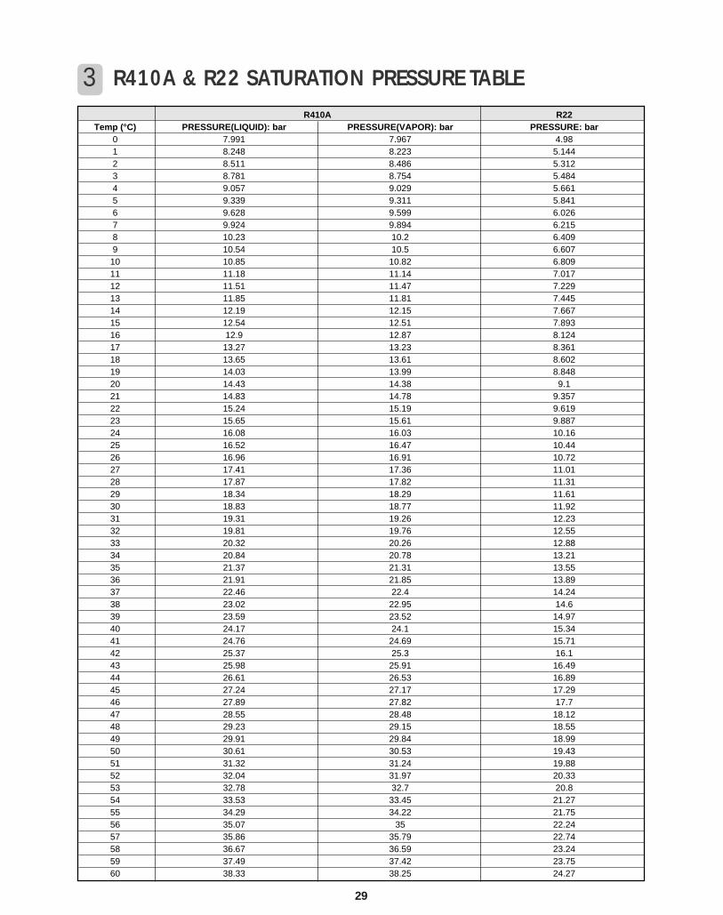
3 R410A & R22 SATURATION PRESSURE TABLER410A R22
Temp (°C) PRESSURE(LIQUID): bar PRESSURE(VAPOR): bar PRESSURE: bar0 7.991 7.967 4.981 8.248 8.223 5.1442 8.511 8.486 5.3123 8.781 8.754 5.4844 9.057 9.029 5.6615 9.339 9.311 5.8416 9.628 9.599 6.0267 9.924 9.894 6.2158 10.23 10.2 6.4099 10.54 10.5 6.607
10 10.85 10.82 6.80911 11.18 11.14 7.01712 11.51 11.47 7.22913 11.85 11.81 7.44514 12.19 12.15 7.66715 12.54 12.51 7.89316 12.9 12.87 8.12417 13.27 13.23 8.36118 13.65 13.61 8.60219 14.03 13.99 8.84820 14.43 14.38 9.121 14.83 14.78 9.35722 15.24 15.19 9.61923 15.65 15.61 9.88724 16.08 16.03 10.1625 16.52 16.47 10.4426 16.96 16.91 10.7227 17.41 17.36 11.0128 17.87 17.82 11.3129 18.34 18.29 11.6130 18.83 18.77 11.9231 19.31 19.26 12.2332 19.81 19.76 12.5533 20.32 20.26 12.8834 20.84 20.78 13.2135 21.37 21.31 13.5536 21.91 21.85 13.8937 22.46 22.4 14.2438 23.02 22.95 14.639 23.59 23.52 14.9740 24.17 24.1 15.3441 24.76 24.69 15.7142 25.37 25.3 16.143 25.98 25.91 16.4944 26.61 26.53 16.8945 27.24 27.17 17.2946 27.89 27.82 17.747 28.55 28.48 18.1248 29.23 29.15 18.5549 29.91 29.84 18.9950 30.61 30.53 19.4351 31.32 31.24 19.8852 32.04 31.97 20.3353 32.78 32.7 20.854 33.53 33.45 21.2755 34.29 34.22 21.7556 35.07 35 22.2457 35.86 35.79 22.7458 36.67 36.59 23.2459 37.49 37.42 23.7560 38.33 38.25 24.27
Relay RL1
Indoor fanmotor
Compressor
Relay RL2
Outdoorfan motor
Relay RL3
4 wayvalve
TRIAC
DC12V
Operating Mode
Fan Speed
Timer Selec ion
Flap Position
Unit on lamp
Room air temp.
Indoor coil temp.
Outdoor coiltemp
Air clean lamp
Quick lamp
Remote
Emergency
Operation
Signalreceiver
Timer lamp
A/D converter lnitialization
Clock generation
DC power supply
Circuit forrelay driving
Circuit forTRIAC control
SMPS
Circuit for signal receiver
MICROCONTROLLER
Beeper
circuit formotor driving
Steppingmotor
Temp. Setting
ON/OFF
SLEEP
REMOCON
AC220V50Hz
STEPPING MOTORON/OFF
COMPRESSORON/OFF
DC5V
30
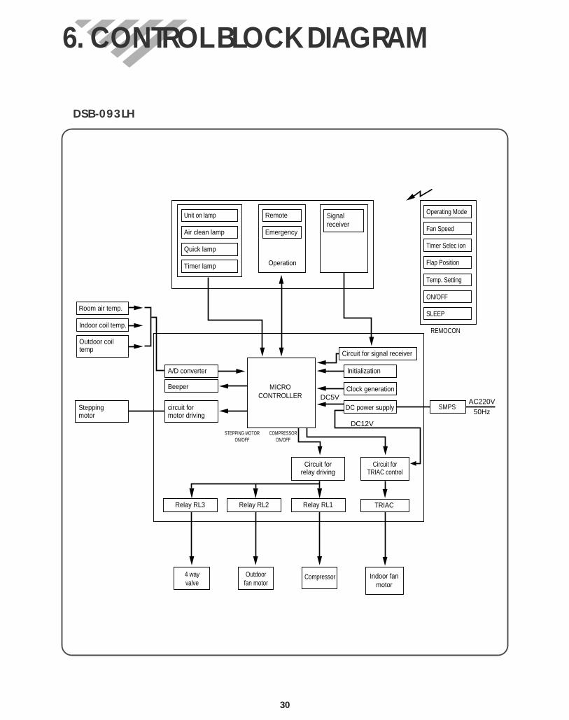
6. CONTROL BLOCK DIAGRAM
DSB-093LH
Relay RL1
Indoor fanmotor
Compressor
Relay RL2
Outdoorfan motor
Relay RL3
4 wayvalve
TRIAC
DC12V
Operating Mode
Fan Speed
Timer Selection
Flap Posi ion
Unit on lamp
Room air temp.
Indoor coil temp.
Outdoor coiltemp
Air clean lamp
Quick lamp
Remote
Emergency
Operation
Signalreceiver
Timer lamp
A/D converter lni ialization
Clock generation
DC power supply
Circuit forrelay driving
Circuit forTRIAC control
Transformer
Circuit for signal receiver
MICROCONTROLLER
Beeper
circuit formotor driving
Steppingmotor
Temp. Setting
ON/OFF
SLEEP
REMOCON
AC220V50Hz
STEPPING MOTORON/OFF
COMPRESSORON/OFF
DC5V
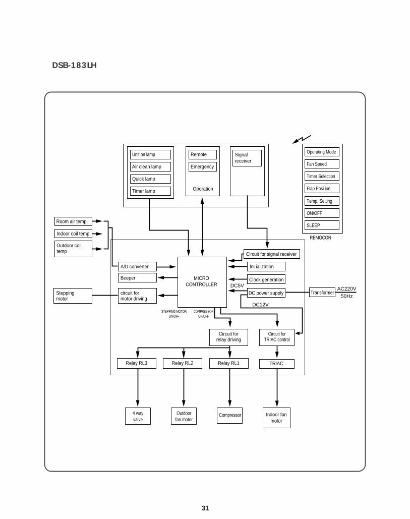
DSB-183LH
31
32
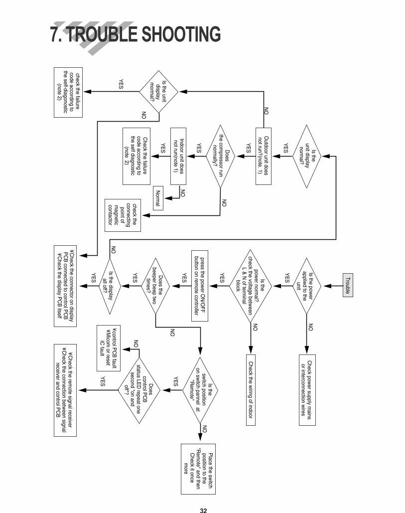
7. TROUBLE SHOOTING
Outdoor unit does
not run?(note. 1)
Does
the compressor run
normally?
Indoor unit doesnot run(note 1)
Check the failure
code according tothe self diagnostic
(note 2)
Is the unit display
morm
al?
check the failure code according to
the self-diagonostic(note 2)
Norm
alcheck the connecting
point ofm
agneticcontactor
YE
S
YE
S
YE
S
YE
S
NO
NO
YE
S
Trouble
Is the power
applied to theunit
Is the pow
er normal?
check the voltage between
L & N
of terminal
block
press the power O
N/O
FF button on rem
ote controller
Does the
beeper beep two
times?
Is the displayall off?
¥ Check the connector on display
PC
B connected to control P
CB
¥ Check the display P
CB
itself
Check pow
er supply mains
or interconnection wires
Check the w
iring of indoor
Is the sw
itch position on sw
itch pannel at "R
emote"
Does
control PC
B
status LED
repeat one second "on and
off"?
¥ control PC
B fault
¥ Micom
or reset IC
fault¥ Check the rem
ote signal receiver¥ C
heck the connection between signal
receiver and control PC
B
Place the sw
itchposition to the
"Rem
ote" and thenC
heck it once m
ore
YE
S
NO
YE
S
NO
NO
NO
NO
YE
S
YE
S
YE
S
YE
S
YE
S
NO
NO
NO
Is theunit display
normal?
33
Note 1)1Neither indoor unit nor outdoor unit runs.
Check the following points first. (There are following case in normal operation)a. Is the timer mode set the "timer ON".b. Is the timer mode set the "timer-OFF" and the time had passed?
2Neither outdoor fan nor compressor runs while indoor fan runs.Check following points first. (There are following cases in normal operation)a. Is the temperature set point suitable?b. Has the 3 minutes time guard for compressor operated?
• Error Code •1When the compressor do not run.
i) Check the voltage between and of terminal block.(Indoor Unit, Outdoor Unit)
ii) Check connecting wire of indoor unit and outdoor unit. iii)Check relay RL1 on power P.C.B
2Check fixing of indoor coil thermistor.3Check the GAS LEAKAGE of the pipe.
YL
Self-Diagnostic Function
34
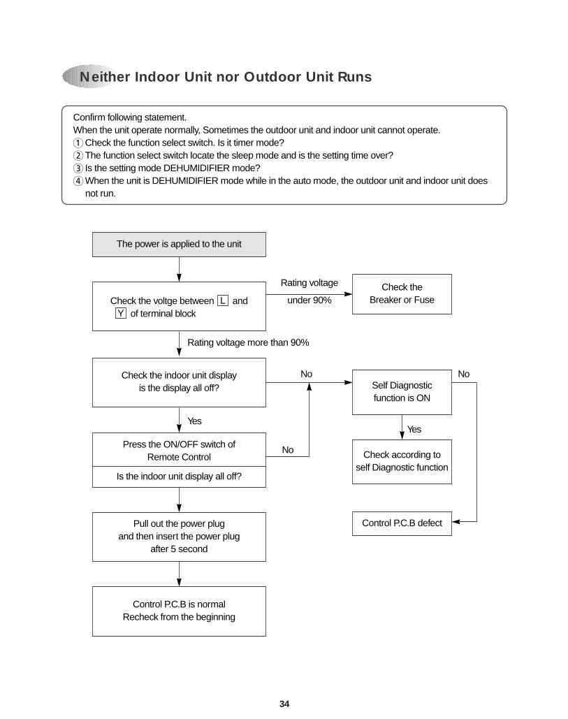
Confirm following statement.When the unit operate normally, Sometimes the outdoor unit and indoor unit cannot operate.1Check the function select switch. Is it timer mode? 2The function select switch locate the sleep mode and is the setting time over?3 Is the setting mode DEHUMIDIFIER mode?4When the unit is DEHUMIDIFIER mode while in the auto mode, the outdoor unit and indoor unit does
not run.
The power is applied to the unit
Check the voltge between and of terminal blockY
LCheck the
Breaker or Fuse
Self Diagnosticfunction is ON
Check according toself Diagnostic function
Control P.C.B defect
Check the indoor unit displayis the display all off?
Press the ON/OFF switch ofRemote Control
Is the indoor unit display all off?
Pull out the power plugand then insert the power plug
after 5 second
Control P.C.B is normalRecheck from the beginning
Rating voltage more than 90%
Rating voltage
under 90%
No No
No
YesYes
Neither Indoor Unit nor Outdoor Unit Runs
35
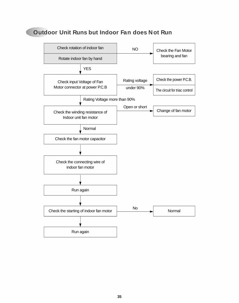
Check rotation of indoor fan
Rotate indoor fan by hand
Check input Voltage of FanMotor connector at power P.C.B
Check the winding resistance of Indoor unit fan motor
Check the fan motor capacitor
Check the connecting wire of indoor fan motor
Run again
Check the starting of indoor fan motor
Run again
Check the Fan Motorbearing and fan
Check the power P.C.B.
The circuit for triac control
Change of fan motor
Normal
NO
Rating voltage
under 90%
Open or short
No
YES
Rating Voltage more than 90%
Normal
Outdoor Unit Runs but Indoor Fan does Not Run
36
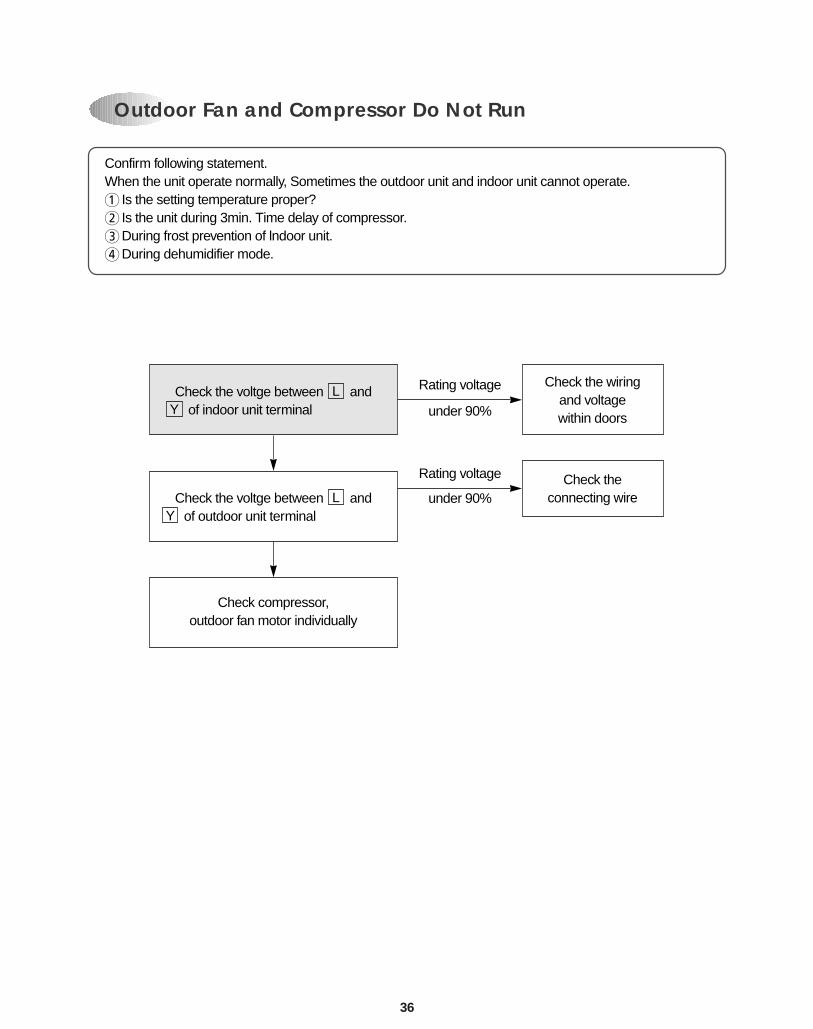
Confirm following statement.When the unit operate normally, Sometimes the outdoor unit and indoor unit cannot operate.1 Is the setting temperature proper? 2 Is the unit during 3min. Time delay of compressor.3During frost prevention of lndoor unit.4During dehumidifier mode.
Outdoor Fan and Compressor Do Not Run
Check the voltge between and of indoor unit terminalY
L
Check the voltge between and of outdoor unit terminalY
L
Check compressor,outdoor fan motor individually
Check theconnecting wire
Check the wiringand voltagewithin doors
Rating voltage
under 90%
Rating voltage
under 90%
37
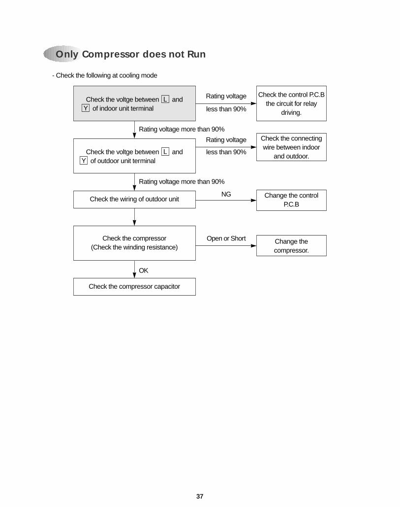
- Check the following at cooling mode
Check the voltge between and of indoor unit terminalY
L
Check the voltge between and of outdoor unit terminalY
L
Check the wiring of outdoor unit
Check the compressor(Check the winding resistance)
Check the compressor capacitor
Check the connectingwire between indoor
and outdoor.
Change the controlP.C.B
Change thecompressor.
Check the control P.C.Bthe circuit for relay
driving.
Rating voltage
less than 90%
NG
Open or Short
Rating voltage
less than 90%
Rating voltage more than 90%
Rating voltage more than 90%
OK
Only Compressor does not Run
43
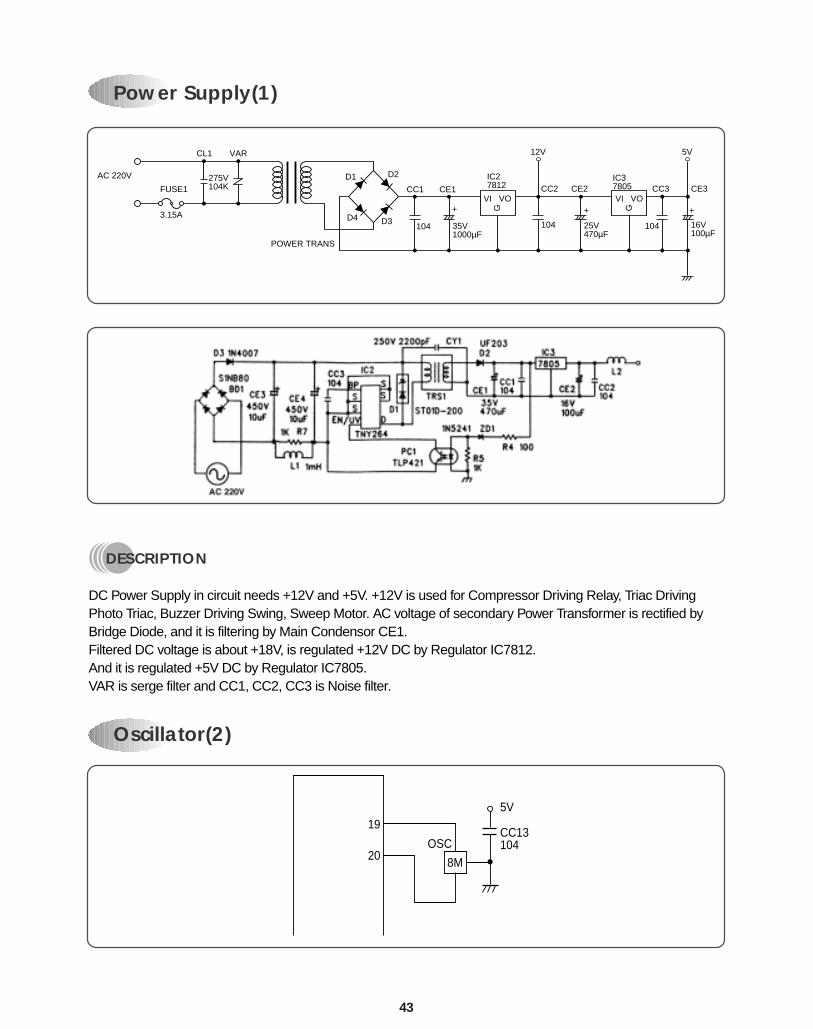
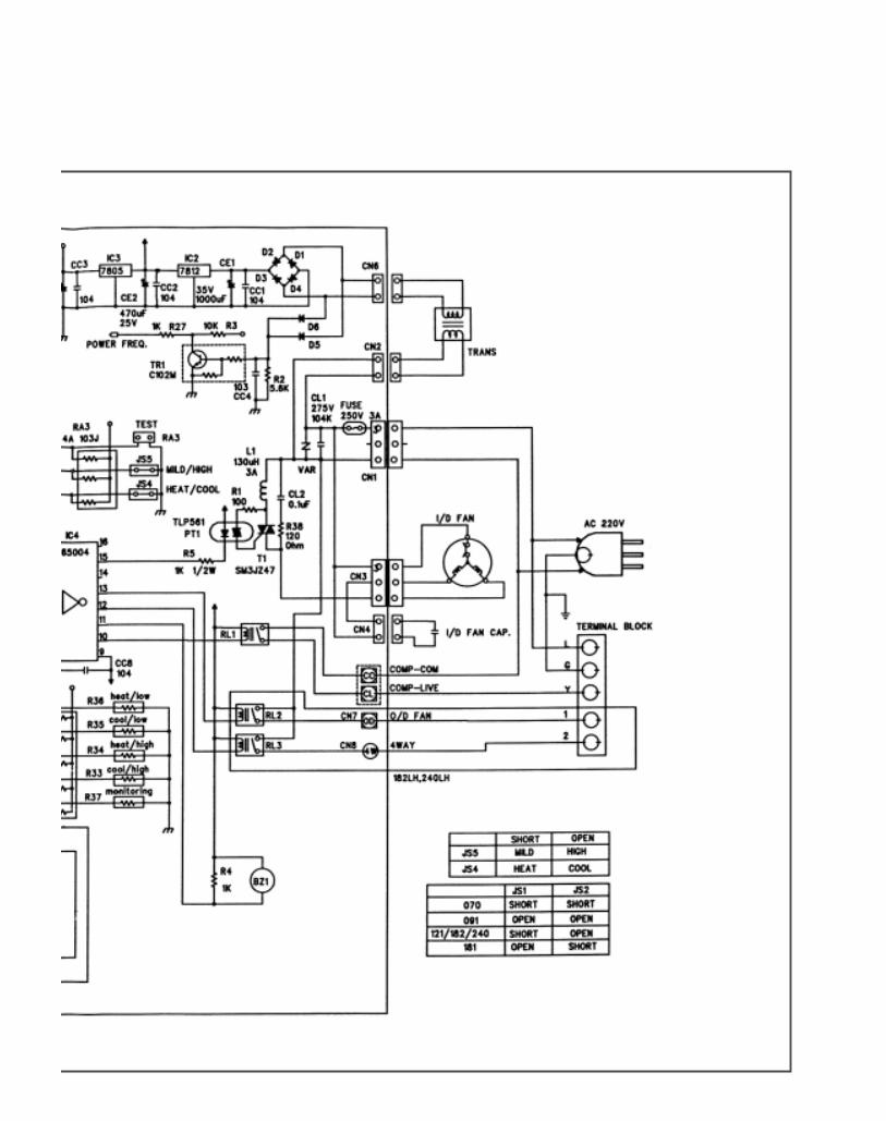
Power Supply(1)
DESCRIPTION
DC Power Supply in circuit needs +12V and +5V. +12V is used for Compressor Driving Relay, Triac DrivingPhoto Triac, Buzzer Driving Swing, Sweep Motor. AC voltage of secondary Power Transformer is rectified byBridge Diode, and it is filtering by Main Condensor CE1.Filtered DC voltage is about +18V, is regulated +12V DC by Regulator IC7812.And it is regulated +5V DC by Regulator IC7805.VAR is serge filter and CC1, CC2, CC3 is Noise filter.
AC 220V
CL1
275V104K
VAR
FUSE1
3.15A
POWER TRANS
D2
CC1 CE1
D3
D1
D4104
+
35V1000µF
IC27812
VI VO
G
IC37805VI VO
G+
25V470µF
CC2 CC3 CE3CE2
104
+
16V100µF
104
12V 5V
Oscillator(2)
19
OSCCC13104
5V
8M20
44
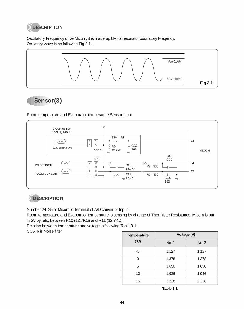
Room temperature and Evaporator temperature Sensor Input
DESCRIPTION
Number 24, 25 of Micom is Terminal of A/D convertor Input.Room temperature and Evaporator temperature is sensing by change of Thermister Resistance, Micom is putin 5V by ratio between R10 (12.7KΩ) and R11 (12.7KΩ).Relation between temperature and voltage is following Table 3-1.CC5, 6 is Noise filter.
Temperature
(°C) No. 1 No. 3
-5 1.127 1.127
0 1.378 1.378
5 1.650 1.650
10 1.936 1.936
15 2.228 2.228
Voltage (V)
Table 3-1
Sensor(3)
070LH,091LH182LH, 240LH
O/C SENSOR
I/C SENSOR
ROOM SENSOR
CN10
330 R8
R7
R6
330
330CC5103
R912.7kF
CC7103
103CC6
23
24
25
MICOM
CN9
R1012.7KF
R1112.7KF
VDD-10%
VSS+10%Fig 2-1
DESCRIPTION
Oscillatory Frequency drive Micom, it is made up 8MHz resonator oscillatory Freqency.Ocillatory wave is as following Fig 2-1.
45
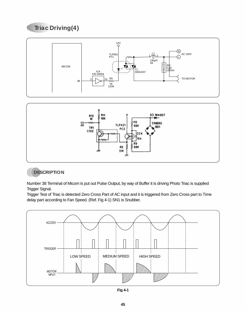
Triac Driving(4)
DESCRIPTION
Number 38 Terminal of Micom is put out Pulse Output, by way of Buffer it is driving Photo Triac is suppliedTrigger Signal.Trigger Test of Triac is detected Zero Cross Part of AC input and it is triggered from Zero Cross part to Timedelay part according to Fan Speed. (Ref. Fig 4-1) SN1 is Snubber.
N
LAC 220V
TO MOTOR
T1SM3JZ47
L11 2
130µH3A
SN10.1µF120Ohm
TLP561PT1
12V
R5
1K1/2W
IC4KID 65004
MICOM
382 15
AC220V
TRIGGER
MOTORNPUT
Fig 4-1
LOW SPEED MEDIUM SPEED HIGH SPEED
46
DESCRIPTION
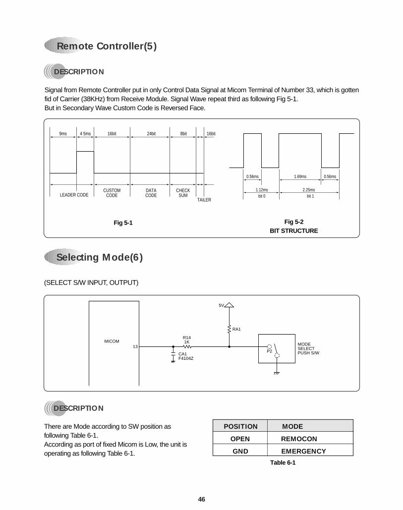
Signal from Remote Controller put in only Control Data Signal at Micom Terminal of Number 33, which is gottenfid of Carrier (38KHz) from Receive Module. Signal Wave repeat third as following Fig 5-1.But in Secondary Wave Custom Code is Reversed Face.
LEADER CODECUSTOM
CODEDATACODE
CHECKSUM
TAILER
9ms 4 5ms 16bit 16bit24bit 8bit
Fig 5-1 Fig 5-2BIT STRUCTURE
Remote Controller(5)
0.56ms 0.56ms1.69ms
1.12ms 2.25msbit 0 bit 1
Selecting Mode(6)
(SELECT S/W INPUT, OUTPUT)
MICOM13
R141K
RA1
5V
CA1F4104Z
P2
MODESELECTPUSH S/W
DESCRIPTION
There are Mode according to SW position asfollowing Table 6-1.According as port of fixed Micom is Low, the unit isoperating as following Table 6-1.
Table 6-1
POSITION MODE
OPEN REMOCON
GND EMERGENCY
47
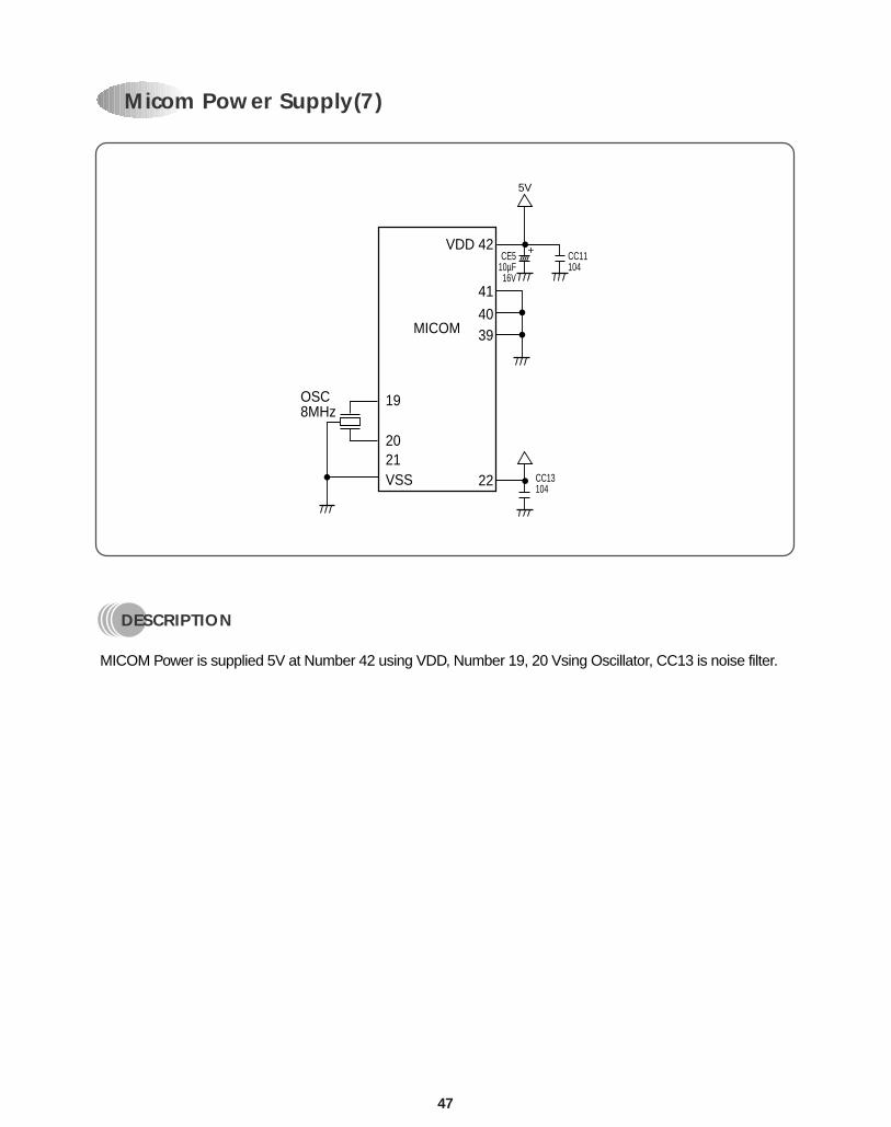
DESCRIPTION
MICOM Power is supplied 5V at Number 42 using VDD, Number 19, 20 Vsing Oscillator, CC13 is noise filter.
Micom Power Supply(7)
VDD 42CE5
10µF16V
CC11104
CC13104
+
5V
41
4039
2221
19OSC8MHz
20
VSS
MICOM
48
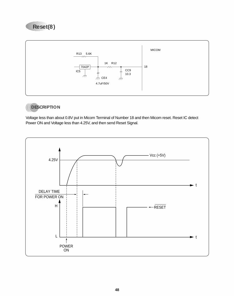
DESCRIPTION
Voltage less than about 0.8V put in Micom Terminal of Number 18 and then Micom reset. Reset IC detectPower ON and Voltage less than 4.25V, and then send Reset Signal.
Reset(8)
R13 5.6K
1K R1218
CC9
CE4
4.7uF/50V
IC5
7042P
10.3
MICOM
4.25V
H
L t
t
POWERON
Vcc (+5V)
DELAY TIMEFOR POWER ON
RESET
49
DESCRIPTION
Micom 34 Terminal put out Buzzer Driving Pulse,its output is driving Buzzer through Buffer.Ocillatory Frequency of buzzer is selected byinternal Micom.This unit is setting at 4KHz.
VCC12V
KID 65004
MICOM
346 11
R41K BZ1
Buzzer Driving(10)
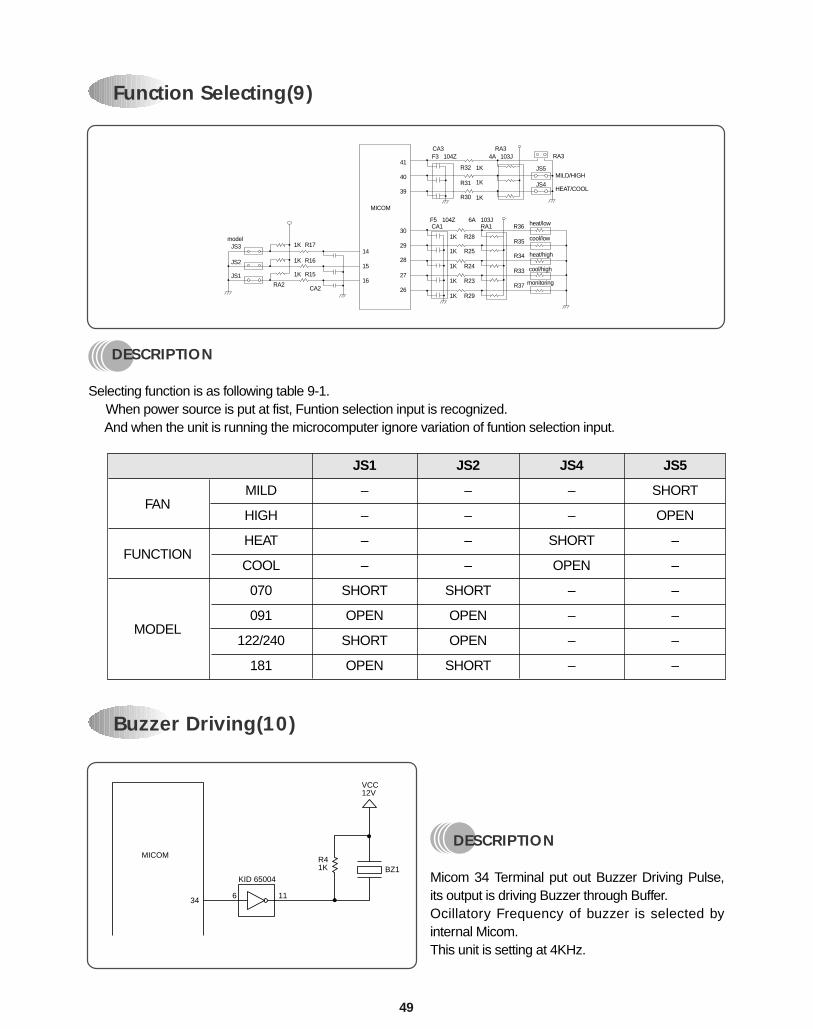
DESCRIPTION
Selecting function is as following table 9-1. When power source is put at fist, Funtion selection input is recognized.
And when the unit is running the microcomputer ignore variation of funtion selection input.
modelJS3
JS2
JS1
1K14
15
16
30
29
28
41
40
39
27
26
1K
1K
1K
1K JS5
JS41K
1K
1K
1K
1K
R28
R32
R31
R30
R25
R24
R23
R35
R34
R33
R37
R29
1K
R17
MICOM
R16
R15
CA2
CA1F5 104Z
RA1 R36 heat/low
heat/high
cool/low
MILD/HIGH
HEAT/COOL
cool/high
monitoring
6A
RA3RA3
4A 103JCA3F3 104Z
103J
RA2
Function Selecting(9)
FAN
FUNCTION
MODEL
MILD
HIGH
HEAT
COOL
070
091
122/240
181
JS1
–
–
–
–
SHORT
OPEN
SHORT
OPEN
JS2
–
–
–
–
SHORT
OPEN
OPEN
SHORT
JS4
–
–
SHORT
OPEN
–
–
–
–
JS5
SHORT
OPEN
–
–
–
–
–
–
50
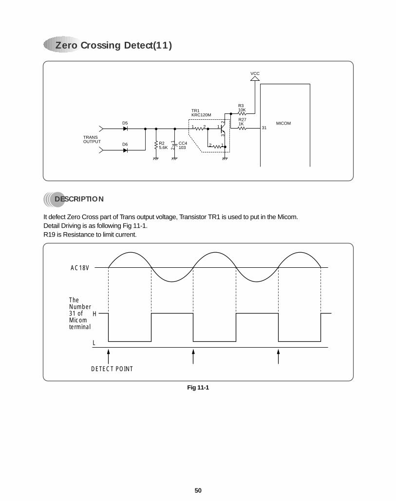
DESCRIPTION
It defect Zero Cross part of Trans output voltage, Transistor TR1 is used to put in the Micom. Detail Driving is as following Fig 11-1.R19 is Resistance to limit current.
MICOM
TRANSOUTPUT
D5
D6 R25.6K
12
CC4103
TR1KRC120M
1 2 1
23
2 1
R310K
R271K
VCC
31
DETECT POINT
H
TheNumber31 ofMicomterminal
AC18V
L
Fig 11-1
Zero Crossing Detect(11)
51
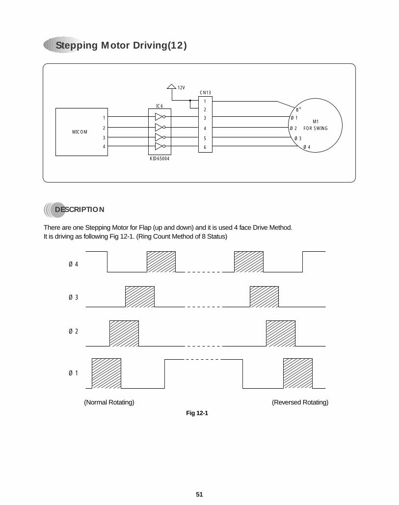
DESCRIPTION
There are one Stepping Motor for Flap (up and down) and it is used 4 face Drive Method.It is driving as following Fig 12-1. (Ring Count Method of 8 Status)
Ø 4
Ø 3
Ø 2
Ø 1
B+
6
5
4
3
2
1
12V
IC6
KID65004
CN13
1
MICOM2
3
4
M1FOR SWING
Ø 4
Ø 3
Ø 2
Ø 1
Fig 12-1
(Normal Rotating) (Reversed Rotating)
Stepping Motor Driving(12)
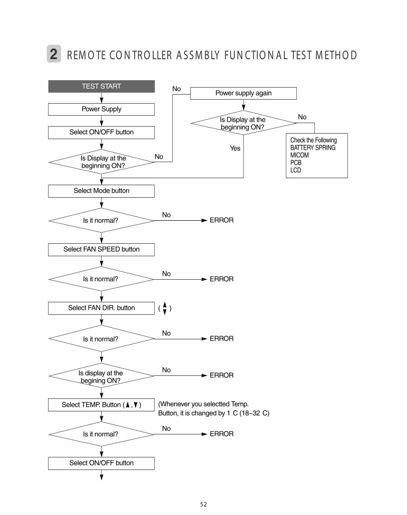
ERRORNo
ERRORNo
ERRORNo
No
No
NoYes
Select ON/OFF button
Select Mode button
Select FAN SPEED button
Select FAN DIR. button
Power Supply
TEST STARTPower supply again
Check the FollowingBATTERY SPRINGMICOMPCBLCD
Is Display at thebeginning ON?
Is Display at thebeginning ON?
Is it normal?
Is it normal?
Is it normal?
2 R EM O TE CO N TR O LLER A S S M B LY FU N CTIO N A L TES T M ETH O D
52
ERRORNo
ERRORNo
(Whenever you selectted Temp.Button, it is changed by 1 C (18~32 C)
( )
Select TEMP. Button ( , )
Select ON/OFF button
Is display at thebegining ON?
Is it normal?
53
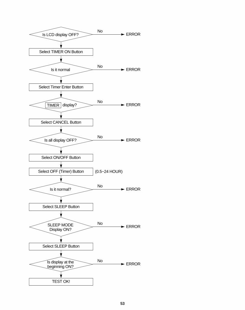
(0.5~24 HOUR)
ERRORNo
Select TIMER ON Button
Select Timer Enter Button
Select CANCEL Button
Select ON/OFF Button
Select OFF (Timer) Button
Select SLEEP Button
Select SLEEP Button
TEST OK!
Is LCD display OFF?
Is it normal
display?TIMER
Is all display OFF?
Is it normal?
SLEEP MODEDisplay ON?
Is display at thebeginning ON?
ERRORNo
ERRORNo
ERRORNo
ERRORNo
ERRORNo
ERRORNo
54
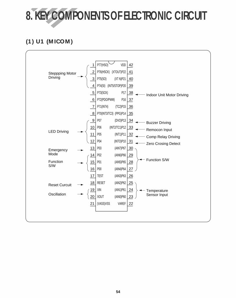
(1) U1 (MICOM)
1
2
3
4
5
6
7
8
9
10
11
12
13
14
15
16
17
18
19
20
21
VDD
(XTOUT)P22
(XT N)P21
(INT5/STOP)P20
P17
P16
(TC2)P15
(PPG)P14
(DVO)P13
(INT2/TC1)P12
(INT1)P11
(INTO)P10
(AIN7)P67
(AIN6)P66
(AIN5)P65
(AIN4)P64
(AIN3)P63
(AIN2)P62
(AIN1)P61
(AIN0)P60
VAREF
P77(HSO)
P76(HSCK)
P75(SO)
P74(SI)
P73(SCK)
P72(PDO/PWM)
P71(INT4)
P70(INT3/TC3)
P07
P06
P05
P04
P03
P02
P01
P00
TEST
RESET
XIN
XOUT
(VASS)VSS
42
41
40
39
38
37
36
35
34
33
32
31
30
29
28
27
26
25
24
23
22
Steppping MotorDriving
Indoor Unit Motor Driving
Buzzer Driving
Remocon Input
Comp Relay Driving
Zero Crosing Detect
Function S/W
TemperatureSensor Input
LED Driving
EmergencyMode
FunctionS/W
Reset Curcuit
Oscillation
8. KEY COMPONENTS OF ELECTRONIC CIRCUIT
55
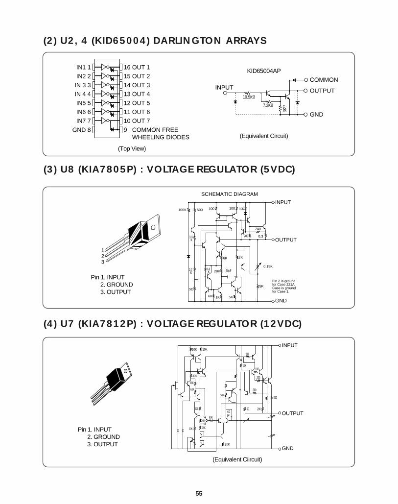
(2) U2, 4 (KID65004) DARLINGTON ARRAYS
(3) U8 (KIA7805P) : VOLTAGE REGULATOR (5VDC)
(4) U7 (KIA7812P) : VOLTAGE REGULATOR (12VDC)
IN1 1 16 OUT 1
IN2 2 15 OUT 2
IN 3 3 14 OUT 3
IN 4 4 13 OUT 4
IN5 5 12 OUT 5
IN6 6 11 OUT 6
IN7 7 10 OUT 7
GND 8 9 COMMON FREE WHEELING DIODES
COMMON
10.5KΩ
7.2KΩ
3KΩ
OUTPUT
GND
INPUT
100K 500 100 100
0.3
10K
6K
500
1K 5K
28K
6K
30pF
2K
5K
200
240
1.4 K
2.7 K
3.3 K
0.19K
INPUT
OUTPUT
GND
SCHEMATIC DIAGRAM
123
Fin 2 is groundfor Cose 221A.Case is groundfor Case 1.
10KINPUT
GND
10K
300
36K
64K
520
26K60K
29K20K
20K
40pF
50K
50 200
300
200
10016K
210
012
OUTPUT
(Top View)
Pin 1. INPUT2. GROUND 3. OUTPUT
Pin 1. INPUT2. GROUND 3. OUTPUT
(Equivalent Circuit)
KID65004AP
(Equivalent Ciircuit)
56
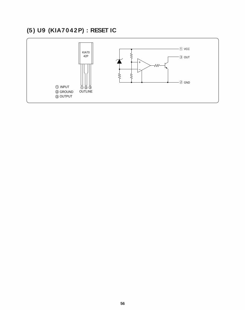
(5) U9 (KIA7042P) : RESET IC
KIA7042P
OUTLINEINPUTGROUNDOUTPUT
VCC1
3
2
OUT
GND
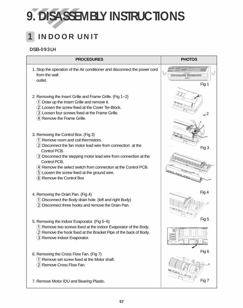
1 INDOOR UNIT
9. DISASSEMBLY INSTRUCTIONS
57
PROCEDURES PHOTOS
1. Stop the operation of the Air conditioner and disconnect the power cordfrom the wall outlet.
2. Removing the Insert Grille and Frame Grille. (Fig 1~2)1Draw up the Insert Grille and remove it.2Loosen the screw fixed at the Cover Ter-Block.3Loosen four screws fixed at the Frame Grille.4Remove the Frame Grille.
3. Removing the Control Box. (Fig 3)1Remove room and coil thermistors.2Disconnect the fan motor lead wire from connection at the
Control PCB.3Disconnect the stepping motor lead wire from connection at the
Control PCB.4Remove the select switch from connection at the Control PCB.5Loosen the screw fixed at the ground wire.6Remove the Control Box
4. Removing the Drain Pan. (Fig 4)1Disconnect the Body drain hole. (left and right Body)2Disconnect three hooks and remove the Drain Pan.
5. Removing the Indoor Evaporator. (Fig 5~6)1Remove two screws fixed at the indoor Evaporator of the Body.2Remove the hook fixed at the Bracket Pipe of the back of Body.3Remove Indoor Evaporator.
6. Removing the Cross Flow Fan. (Fig 7)1Remove set screw fixed at the Motor shaft.2Remove Cross Flow Fan.
7. Remove Motor IDU and Bearing Plastic.
Fig 1
Fig 3
Fig 4
Fig 5
Fig 6
DSB-093LH
ig 2
Fig 7
58
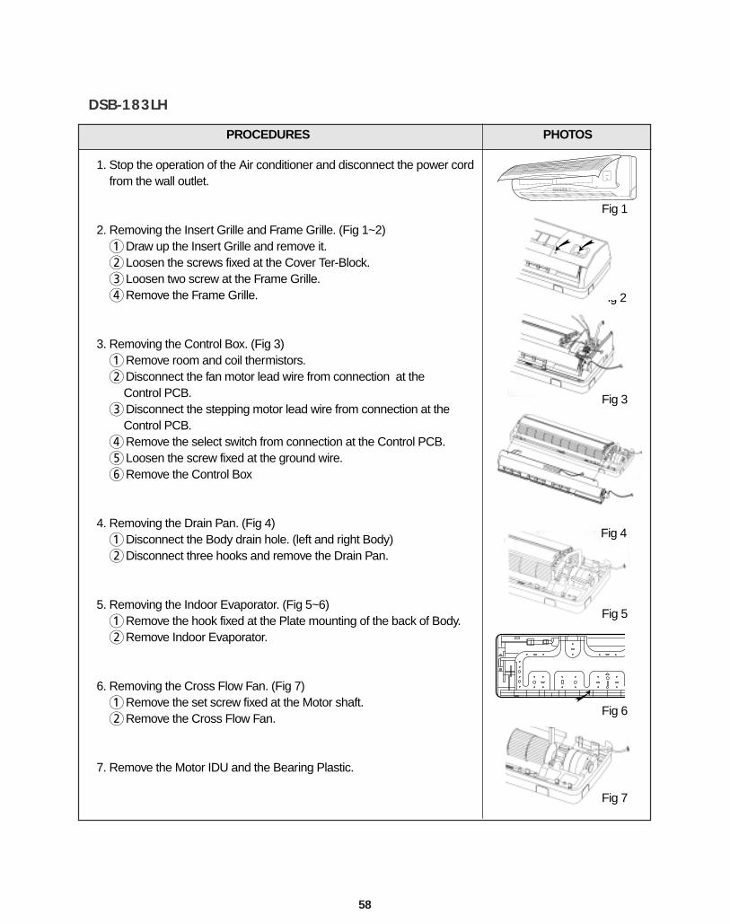
PROCEDURES PHOTOS
1. Stop the operation of the Air conditioner and disconnect the power cordfrom the wall outlet.
2. Removing the Insert Grille and Frame Grille. (Fig 1~2)1Draw up the Insert Grille and remove it.2Loosen the screws fixed at the Cover Ter-Block.3Loosen two screw at the Frame Grille.4Remove the Frame Grille.
3. Removing the Control Box. (Fig 3)1Remove room and coil thermistors.2Disconnect the fan motor lead wire from connection at the
Control PCB.3Disconnect the stepping motor lead wire from connection at the
Control PCB.4Remove the select switch from connection at the Control PCB.5Loosen the screw fixed at the ground wire.6Remove the Control Box
4. Removing the Drain Pan. (Fig 4)1Disconnect the Body drain hole. (left and right Body)2Disconnect three hooks and remove the Drain Pan.
5. Removing the Indoor Evaporator. (Fig 5~6)1Remove the hook fixed at the Plate mounting of the back of Body.2Remove Indoor Evaporator.
6. Removing the Cross Flow Fan. (Fig 7)1Remove the set screw fixed at the Motor shaft.2Remove the Cross Flow Fan.
7. Remove the Motor IDU and the Bearing Plastic.
Fig 1
Fig 3
Fig 4
Fig 5
Fig 6
DSB-183LH
ig 2
Fig 7
59
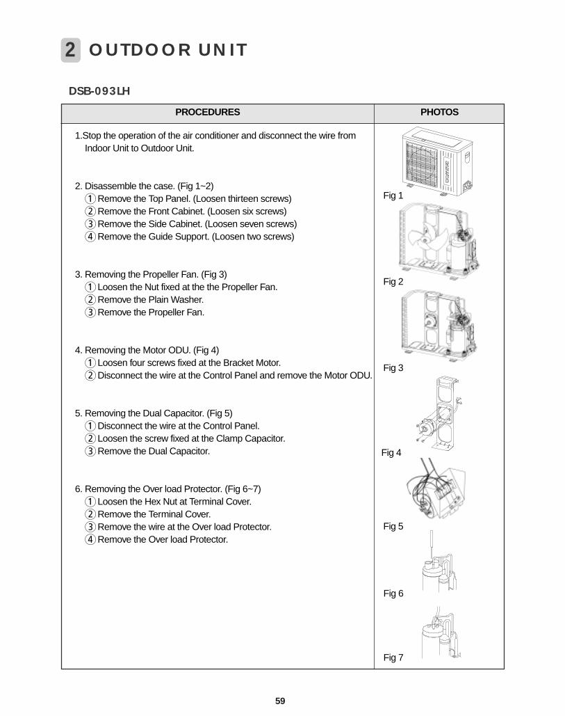
DSB-093LH
PROCEDURES PHOTOS
1.Stop the operation of the air conditioner and disconnect the wire fromIndoor Unit to Outdoor Unit.
2. Disassemble the case. (Fig 1~2)1Remove the Top Panel. (Loosen thirteen screws)2Remove the Front Cabinet. (Loosen six screws)3Remove the Side Cabinet. (Loosen seven screws)4Remove the Guide Support. (Loosen two screws)
3. Removing the Propeller Fan. (Fig 3)1Loosen the Nut fixed at the the Propeller Fan.2Remove the Plain Washer.3Remove the Propeller Fan.
4. Removing the Motor ODU. (Fig 4)1Loosen four screws fixed at the Bracket Motor.2Disconnect the wire at the Control Panel and remove the Motor ODU.
5. Removing the Dual Capacitor. (Fig 5)1Disconnect the wire at the Control Panel.2Loosen the screw fixed at the Clamp Capacitor.3Remove the Dual Capacitor.
6. Removing the Over load Protector. (Fig 6~7)1Loosen the Hex Nut at Terminal Cover.2Remove the Terminal Cover.3Remove the wire at the Over load Protector.4Remove the Over load Protector.
Fig 5
Fig 4
Fig 6
Fig 7
Fig 1
Fig 3
Fig 2
2 OUTDOOR UNIT
60
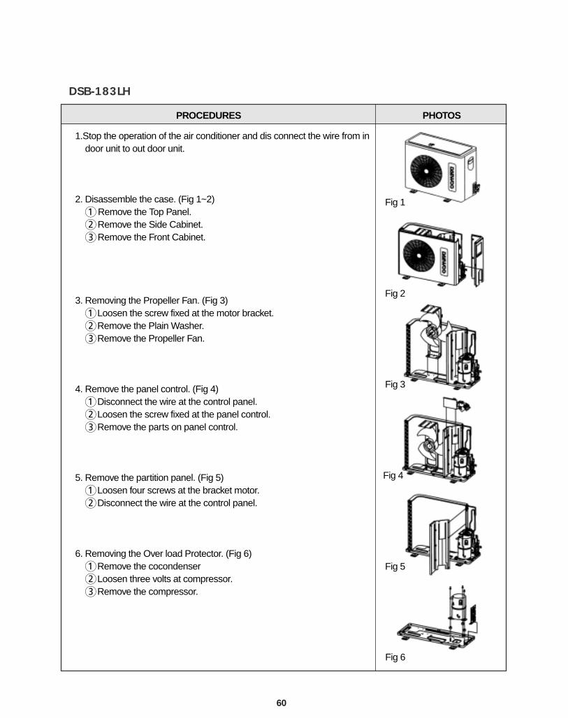
DSB-183LH
PROCEDURES PHOTOS
1.Stop the operation of the air conditioner and dis connect the wire from indoor unit to out door unit.
2. Disassemble the case. (Fig 1~2) 1Remove the Top Panel. 2Remove the Side Cabinet.3Remove the Front Cabinet.
3. Removing the Propeller Fan. (Fig 3)1Loosen the screw fixed at the motor bracket.2Remove the Plain Washer.3Remove the Propeller Fan.
4. Remove the panel control. (Fig 4)1Disconnect the wire at the control panel.2Loosen the screw fixed at the panel control.3Remove the parts on panel control.
5. Remove the partition panel. (Fig 5)1Loosen four screws at the bracket motor.2Disconnect the wire at the control panel.
6. Removing the Over load Protector. (Fig 6)1Remove the cocondenser2Loosen three volts at compressor.3Remove the compressor.
Fig 1
Fig 2
Fig 3
Fig 5
Fig 4
Fig 6
62
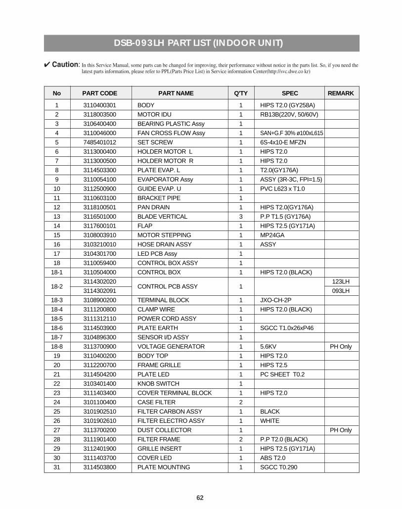
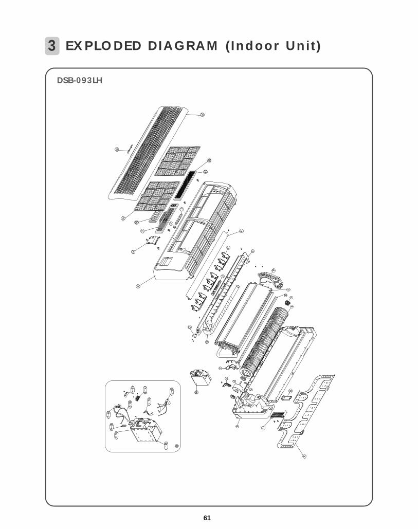
DSB-093LH PART LIST (INDOOR UNIT)
No PART CODE PART NAME Q'TY SPEC REMARK
1 3110400301 BODY 1 HIPS T2.0 (GY258A)
2 3118003500 MOTOR IDU 1 RB13B(220V, 50/60V)
3 3106400400 BEARING PLASTIC Assy 1
4 3110046000 FAN CROSS FLOW Assy 1 SAN+G.F 30% ø100xL615
5 7485401012 SET SCREW 1 6S-4x10-E MFZN
6 3113000400 HOLDER MOTOR L 1 HIPS T2.0
7 3113000500 HOLDER MOTOR R 1 HIPS T2.0
8 3114503300 PLATE EVAP. L 1 T2.0(GY176A)
9 3110054100 EVAPORATOR Assy 1 ASSY (3R-3C, FPI=1.5)
10 3112500900 GUIDE EVAP. U 1 PVC L623 x T1.0
11 3110603100 BRACKET PIPE 1
12 3118100501 PAN DRAIN 1 HIPS T2.0(GY176A)
13 3116501000 BLADE VERTICAL 3 P.P T1.5 (GY176A)
14 3117600101 FLAP 1 HIPS T2.5 (GY171A)
15 3108003910 MOTOR STEPPING 1 MP24GA
16 3103210010 HOSE DRAIN ASSY 1 ASSY
17 3104301700 LED PCB Assy 1
18 3110059400 CONTROL BOX ASSY 1
18-1 3110504000 CONTROL BOX 1 HIPS T2.0 (BLACK)
18-23114302020
CONTROL PCB ASSY 1123LH
3114302091 093LH
18-3 3108900200 TERMINAL BLOCK 1 JXO-CH-2P
18-4 3111200800 CLAMP WIRE 1 HIPS T2.0 (BLACK)
18-5 3111312110 POWER CORD ASSY 1
18-6 3114503900 PLATE EARTH 1 SGCC T1.0x26xP46
18-7 3104896300 SENSOR I/D ASSY 1
18-8 3113700900 VOLTAGE GENERATOR 1 5.6KV PH Only
19 3110400200 BODY TOP 1 HIPS T2.0
20 3112200700 FRAME GRILLE 1 HIPS T2.5
21 3114504200 PLATE LED 1 PC SHEET T0.2
22 3103401400 KNOB SWITCH 1
23 3111403400 COVER TERMINAL BLOCK 1 HIPS T2.0
24 3101100400 CASE FILTER 2
25 3101902510 FILTER CARBON ASSY 1 BLACK
26 3101902610 FILTER ELECTRO ASSY 1 WHITE
27 3113700200 DUST COLLECTOR 1 PH Only
28 3111901400 FILTER FRAME 2 P.P T2.0 (BLACK)
29 3112401900 GRILLE INSERT 1 HIPS T2.5 (GY171A)
30 3111403700 COVER LED 1 ABS T2.0
31 3114503800 PLATE MOUNTING 1 SGCC T0.290
4 Caution: In this Service Manual, some parts can be changed for improving, their performance without notice in the parts list. So, if you need thelatest parts information, please refer to PPL(Parts Price List) in Service information Center(http://svc.dwe.co kr)
64
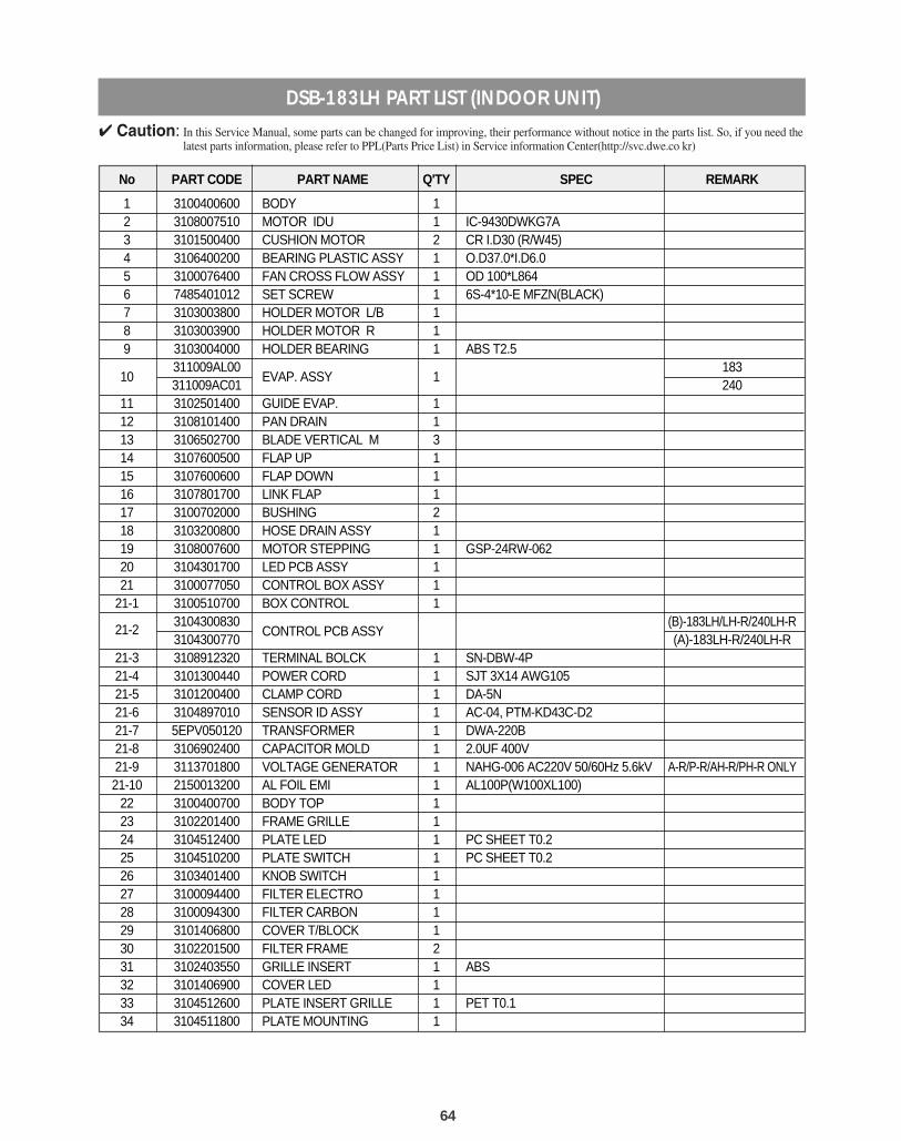
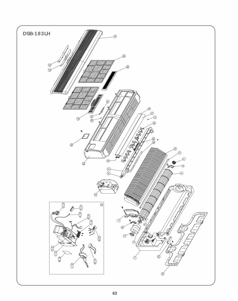
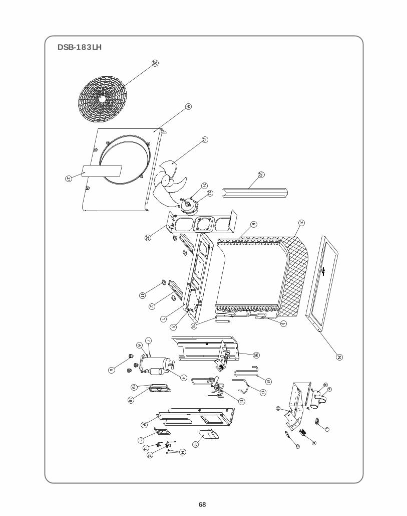
DSB-183LH PART LIST (INDOOR UNIT)
No PART CODE PART NAME Q'TY SPEC REMARK
1 3100400600 BODY 12 3108007510 MOTOR IDU 1 IC-9430DWKG7A 3 3101500400 CUSHION MOTOR 2 CR I.D30 (R/W45)4 3106400200 BEARING PLASTIC ASSY 1 O.D37.0*I.D6.05 3100076400 FAN CROSS FLOW ASSY 1 OD 100*L8646 7485401012 SET SCREW 1 6S-4*10-E MFZN(BLACK)7 3103003800 HOLDER MOTOR L/B 18 3103003900 HOLDER MOTOR R 19 3103004000 HOLDER BEARING 1 ABS T2.5
10311009AL00
EVAP. ASSY 1183
311009AC01 24011 3102501400 GUIDE EVAP. 112 3108101400 PAN DRAIN 113 3106502700 BLADE VERTICAL M 314 3107600500 FLAP UP 115 3107600600 FLAP DOWN 116 3107801700 LINK FLAP 117 3100702000 BUSHING 218 3103200800 HOSE DRAIN ASSY 119 3108007600 MOTOR STEPPING 1 GSP-24RW-06220 3104301700 LED PCB ASSY 121 3100077050 CONTROL BOX ASSY 1
21-1 3100510700 BOX CONTROL 1
21-23104300830
CONTROL PCB ASSY(B)-183LH/LH-R/240LH-R
3104300770 (A)-183LH-R/240LH-R21-3 3108912320 TERMINAL BOLCK 1 SN-DBW-4P21-4 3101300440 POWER CORD 1 SJT 3X14 AWG105 21-5 3101200400 CLAMP CORD 1 DA-5N21-6 3104897010 SENSOR ID ASSY 1 AC-04, PTM-KD43C-D221-7 5EPV050120 TRANSFORMER 1 DWA-220B21-8 3106902400 CAPACITOR MOLD 1 2.0UF 400V21-9 3113701800 VOLTAGE GENERATOR 1 NAHG-006 AC220V 50/60Hz 5.6kV A-R/P-R/AH-R/PH-R ONLY21-10 2150013200 AL FOIL EMI 1 AL100P(W100XL100)
22 3100400700 BODY TOP 123 3102201400 FRAME GRILLE 124 3104512400 PLATE LED 1 PC SHEET T0.225 3104510200 PLATE SWITCH 1 PC SHEET T0.226 3103401400 KNOB SWITCH 127 3100094400 FILTER ELECTRO 128 3100094300 FILTER CARBON 129 3101406800 COVER T/BLOCK 130 3102201500 FILTER FRAME 231 3102403550 GRILLE INSERT 1 ABS32 3101406900 COVER LED 133 3104512600 PLATE INSERT GRILLE 1 PET T0.134 3104511800 PLATE MOUNTING 1
4 Caution: In this Service Manual, some parts can be changed for improving, their performance without notice in the parts list. So, if you need thelatest parts information, please refer to PPL(Parts Price List) in Service information Center(http://svc.dwe.co kr)
66
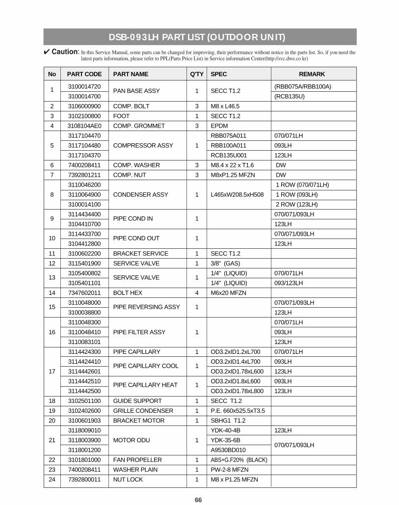
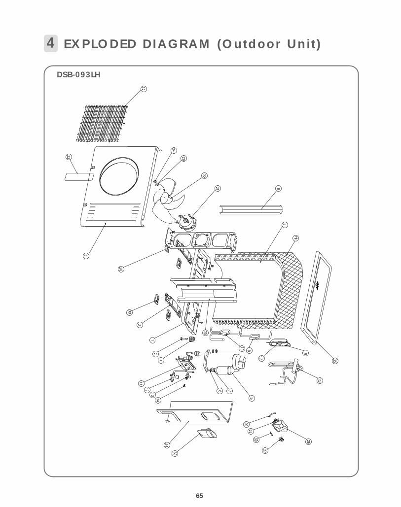
DSB-093LH PART LIST (OUTDOOR UNIT)
No PART CODE PART NAME Q'TY SPEC REMARK
1 3100014720PAN BASE ASSY 1 SECC T1.2
(RBB075A/RBB100A)
3100014700 (RCB135U)
2 3106000900 COMP. BOLT 3 M8 x L46.5
3 3102100800 FOOT 1 SECC T1.2
4 3108104AE0 COMP. GROMMET 3 EPDM
3117104470 RBB075A011 070/071LH
5 3117104480 COMPRESSOR ASSY 1 RBB100A011 093LH
3117104370 RCB135U001 123LH
6 7400208411 COMP. WASHER 3 M8.4 x 22 x T1.6 DW
7 7392801211 COMP. NUT 3 M8xP1.25 MFZN DW
3110046200 1 ROW (070/071LH)
8 3110064900 CONDENSER ASSY 1 L465xW208.5xH508 1 ROW (093LH)
3100014100 2 ROW (123LH)
93114434400
PIPE COND IN 1070/071/093LH
3104410700 123LH
103114433700
PIPE COND OUT 1070/071/093LH
3104412800 123LH
11 3100602200 BRACKET SERVICE 1 SECC T1.2
12 3115401900 SERVICE VALVE 1 3/8" (GAS)
133105400802
SERVICE VALVE 11/4" (LIQUID) 070/071LH
3105401101 1/4" (LIQUID) 093/123LH
14 7347602011 BOLT HEX 4 M6x20 MFZN
153110048000
PIPE REVERSING ASSY 1070/071/093LH
3100038800 123LH
3110048300 070/071LH
16 3110048410 PIPE FILTER ASSY 1 093LH
3110083101 123LH
3114424300 PIPE CAPILLARY 1 OD3.2xID1.2xL700 070/071LH
3114424410PIPE CAPILLARY COOL 1
OD3.2xID1.4xL700 093LH
17 3114442601 OD3.2xID1.78xL600 123LH
3114442510PIPE CAPILLARY HEAT 1
OD3.2xID1.8xL600 093LH
3114442500 OD3.2xID1.78xL800 123LH
18 3102501100 GUIDE SUPPORT 1 SECC T1.2
19 3102402600 GRILLE CONDENSER 1 P.E. 660x525.5xT3.5
20 3100601903 BRACKET MOTOR 1 SBHG1 T1.2
3118009010 YDK-40-4B 123LH
21 3118003900 MOTOR ODU 1 YDK-35-6B070/071/093LH
3118001200 A9530BD010
22 3101801000 FAN PROPELLER 1 ABS+G.F20% (BLACK)
23 7400208411 WASHER PLAIN 1 PW-2-8 MFZN
24 7392800011 NUT LOCK 1 M8 x P1.25 MFZN
4 Caution: In this Service Manual, some parts can be changed for improving, their performance without notice in the parts list. So, if you need thelatest parts information, please refer to PPL(Parts Price List) in Service information Center(http://svc.dwe.co kr)
67
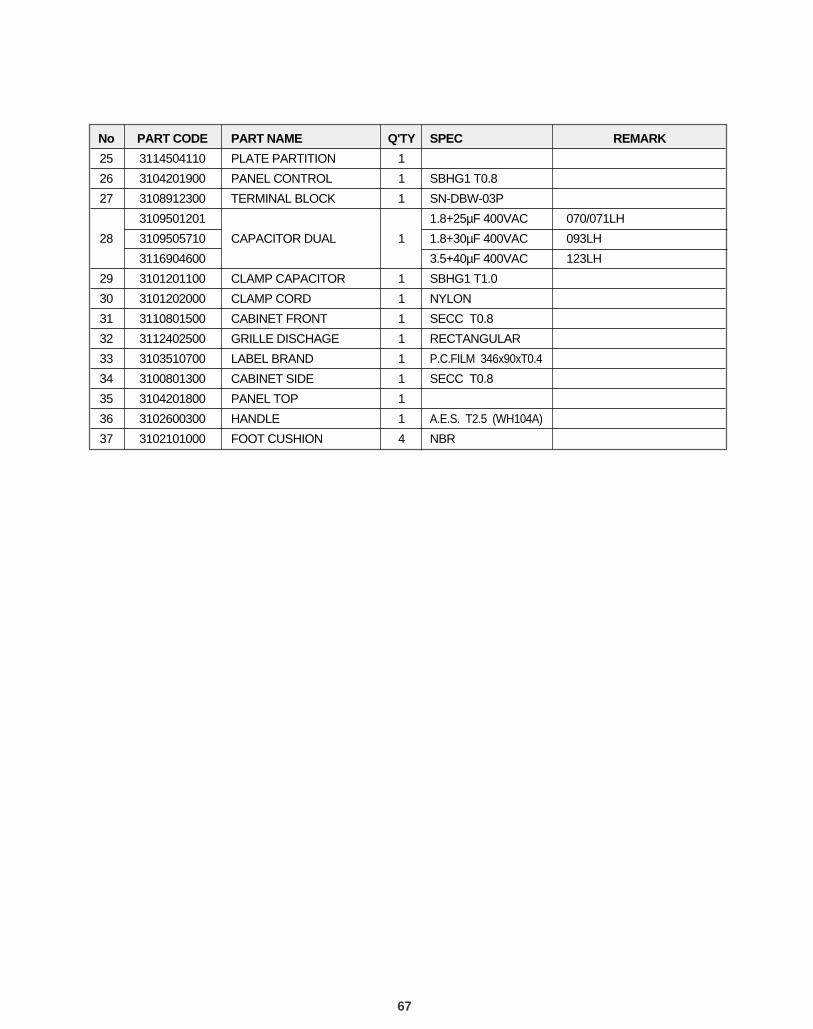
No PART CODE PART NAME Q'TY SPEC REMARK
25 3114504110 PLATE PARTITION 1
26 3104201900 PANEL CONTROL 1 SBHG1 T0.8
27 3108912300 TERMINAL BLOCK 1 SN-DBW-03P
3109501201 1.8+25µF 400VAC 070/071LH
28 3109505710 CAPACITOR DUAL 1 1.8+30µF 400VAC 093LH
3116904600 3.5+40µF 400VAC 123LH
29 3101201100 CLAMP CAPACITOR 1 SBHG1 T1.0
30 3101202000 CLAMP CORD 1 NYLON
31 3110801500 CABINET FRONT 1 SECC T0.8
32 3112402500 GRILLE DISCHAGE 1 RECTANGULAR
33 3103510700 LABEL BRAND 1 P.C.FILM 346x90xT0.4
34 3100801300 CABINET SIDE 1 SECC T0.8
35 3104201800 PANEL TOP 1
36 3102600300 HANDLE 1 A.E.S. T2.5 (WH104A)
37 3102101000 FOOT CUSHION 4 NBR
69
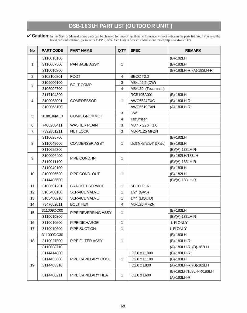
No PART CODE PART NAME Q'TY SPEC REMARK
3110016100 (B)-182LH
1 3110007500 PAN BASE ASSY 1 (B)-183LH
3110016200 (B)-183LH-R, (A)-183LH-R
2 3102100201 FOOT 4 SECC T2.0
33106000100
BOLT COMP.3 M8xL46.5 (DW)
3106002700 4 M8xL30 (Tecumseh)
3117104390 RCB195A001 (B)-183LH
4 3100068001 COMPRESSOR 1 AWG5524EXC (B)-183LH-R
3100068100 AWG5519EXN (A)-183LH-R
5 3108104AE0 COMP. GROMMET3 DW
4 Tecumseh
6 7400208411 WASHER PLAIN 3 M8.4 x 22 x T1.6
7 7392801211 NUT LOCK 3 M8xP1.25 MFZN
3110025700 (B)-182LH
8 3110049600 CONDENSER ASSY 1 L568.4xH575xW44 (2Rx2C) (B)-183LH
3110025800 (B)/(A)-183LH-R
93100006400
PIPE COND. IN 1(B)-182LH/183LH
3110011100 (B)/(A)-183LH-R
3110049100 (B)-183LH
10 3100006520 PIPE COND. OUT 1 (B)-182LH
3114405600 (B)/(A)-183LH-R
11 3100601201 BRACKET SERVICE 1 SECC T1.6
12 3105400100 SERVICE VALVE 1 1/2" (GAS)
13 3105400210 SERVICE VALVE 1 1/4" (LIQUID)
14 7347602011 BOLT HEX 4 M6xL20 MFZN
15311009DC00
PIPE REVERSING ASSY 1(B)-183LH
3110010800 (B)/(A)-183LH-R
16 3110010500 PIPE DICHARGE 1 L-R ONLY
17 3110010600 PIPE SUCTION 1 L-R ONLY
311009DC30 (B)-183LH
18 3110027500 PIPE FILTER ASSY 1 (B)-183LH-R
3110008710 (A)-183LH-R, (B)-182LH
3114414800 ID2.0 x L1000 (B)-183LH-R
3114455600 PIPE CAPILLARY COOL 1 ID2.0 x L1100 (B)-183LH
19 3114403310 ID2.0 x L800 (A)-183LH-R, (B)-182LH
3114406211 PIPE CAPILLARY HEAT 1 ID2.0 x L600(B)-182LH/183LH-R/183LH
(A)-183LH-R
DSB-183LH PART LIST (OUTDOOR UNIT )
4 Caution: In this Service Manual, some parts can be changed for improving, their performance without notice in the parts list. So, if you need thelatest parts information, please refer to PPL(Parts Price List) in Service information Center(http://svc.dwe.co kr)
70
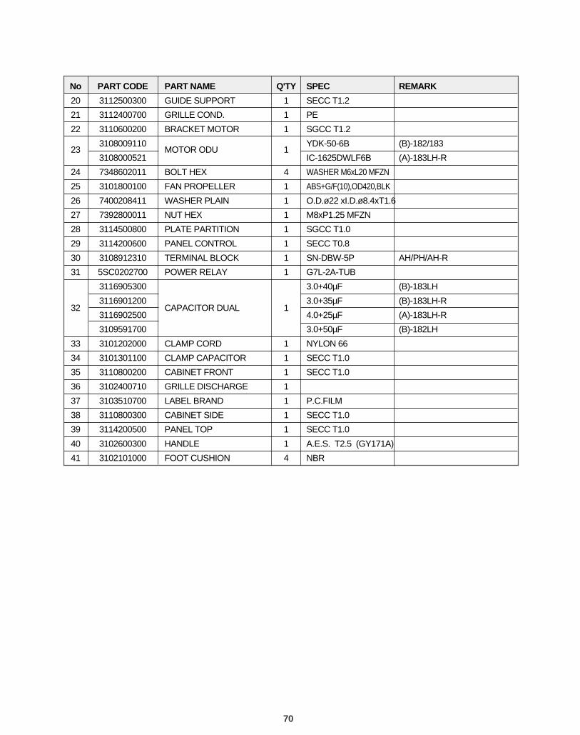
No PART CODE PART NAME Q'TY SPEC REMARK
20 3112500300 GUIDE SUPPORT 1 SECC T1.2
21 3112400700 GRILLE COND. 1 PE
22 3110600200 BRACKET MOTOR 1 SGCC T1.2
233108009110
MOTOR ODU 1YDK-50-6B (B)-182/183
3108000521 IC-1625DWLF6B (A)-183LH-R
24 7348602011 BOLT HEX 4 WASHER M6xL20 MFZN
25 3101800100 FAN PROPELLER 1 ABS+G/F(10),OD420,BLK
26 7400208411 WASHER PLAIN 1 O.D.ø22 xI.D.ø8.4xT1.6
27 7392800011 NUT HEX 1 M8xP1.25 MFZN
28 3114500800 PLATE PARTITION 1 SGCC T1.0
29 3114200600 PANEL CONTROL 1 SECC T0.8
30 3108912310 TERMINAL BLOCK 1 SN-DBW-5P AH/PH/AH-R
31 5SC0202700 POWER RELAY 1 G7L-2A-TUB
3116905300 3.0+40µF (B)-183LH
323116901200
CAPACITOR DUAL 13.0+35µF (B)-183LH-R
3116902500 4.0+25µF (A)-183LH-R
3109591700 3.0+50µF (B)-182LH
33 3101202000 CLAMP CORD 1 NYLON 66
34 3101301100 CLAMP CAPACITOR 1 SECC T1.0
35 3110800200 CABINET FRONT 1 SECC T1.0
36 3102400710 GRILLE DISCHARGE 1
37 3103510700 LABEL BRAND 1 P.C.FILM
38 3110800300 CABINET SIDE 1 SECC T1.0
39 3114200500 PANEL TOP 1 SECC T1.0
40 3102600300 HANDLE 1 A.E.S. T2.5 (GY171A)
41 3102101000 FOOT CUSHION 4 NBR
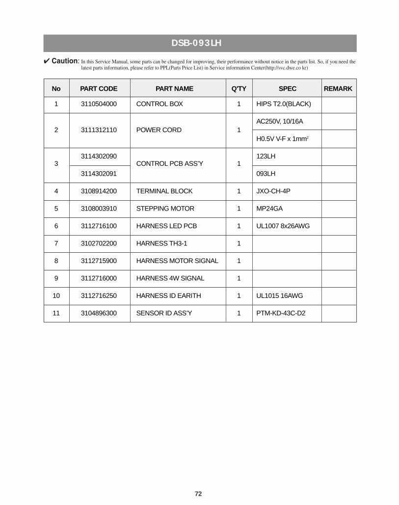
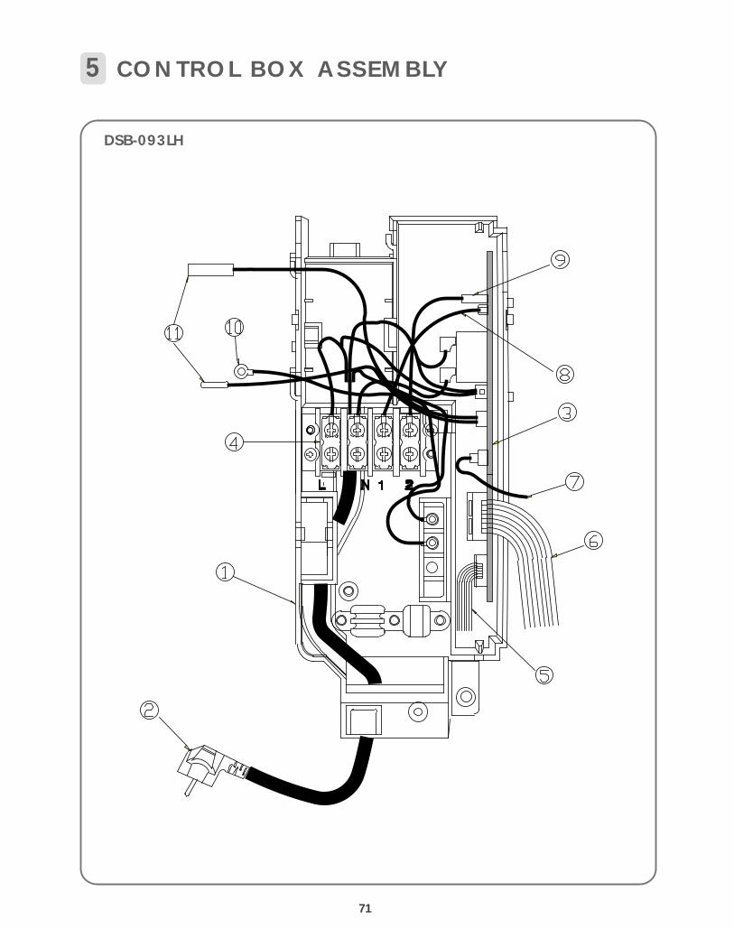
72
DSB-093LH
No PART CODE PART NAME Q'TY SPEC REMARK
1 3110504000 CONTROL BOX 1 HIPS T2.0(BLACK)
2 3111312110 POWER CORD 1AC250V, 10/16A
H0.5V V-F x 1mm2
33114302090
CONTROL PCB ASS’Y 1123LH
3114302091 093LH
4 3108914200 TERMINAL BLOCK 1 JXO-CH-4P
5 3108003910 STEPPING MOTOR 1 MP24GA
6 3112716100 HARNESS LED PCB 1 UL1007 8x26AWG
7 3102702200 HARNESS TH3-1 1
8 3112715900 HARNESS MOTOR SIGNAL 1
9 3112716000 HARNESS 4W SIGNAL 1
10 3112716250 HARNESS ID EARITH 1 UL1015 16AWG
11 3104896300 SENSOR ID ASS’Y 1 PTM-KD-43C-D2
4 Caution: In this Service Manual, some parts can be changed for improving, their performance without notice in the parts list. So, if you need thelatest parts information, please refer to PPL(Parts Price List) in Service information Center(http://svc.dwe.co kr)
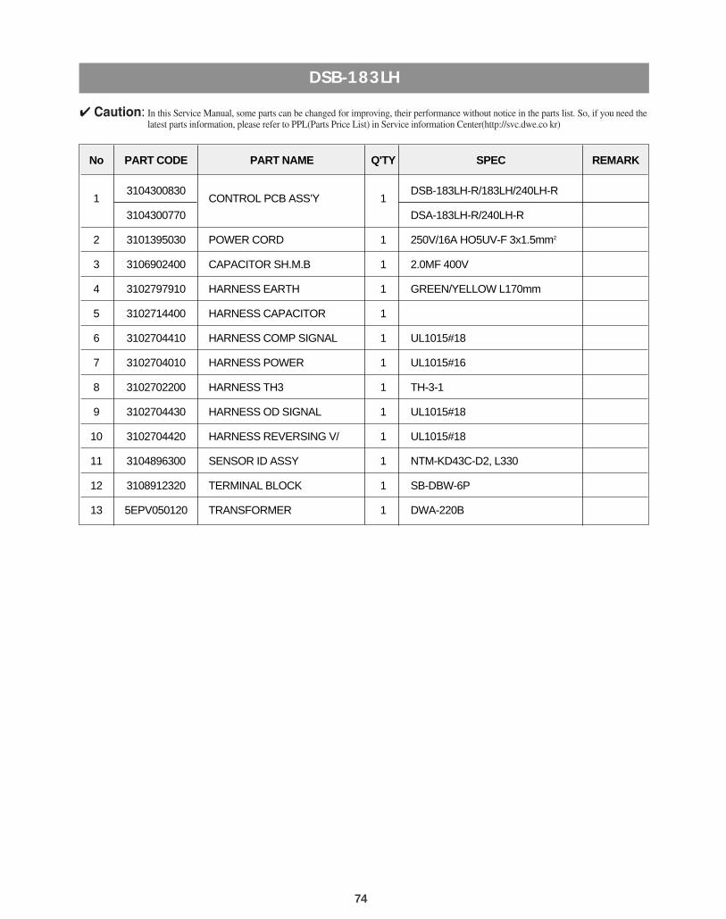
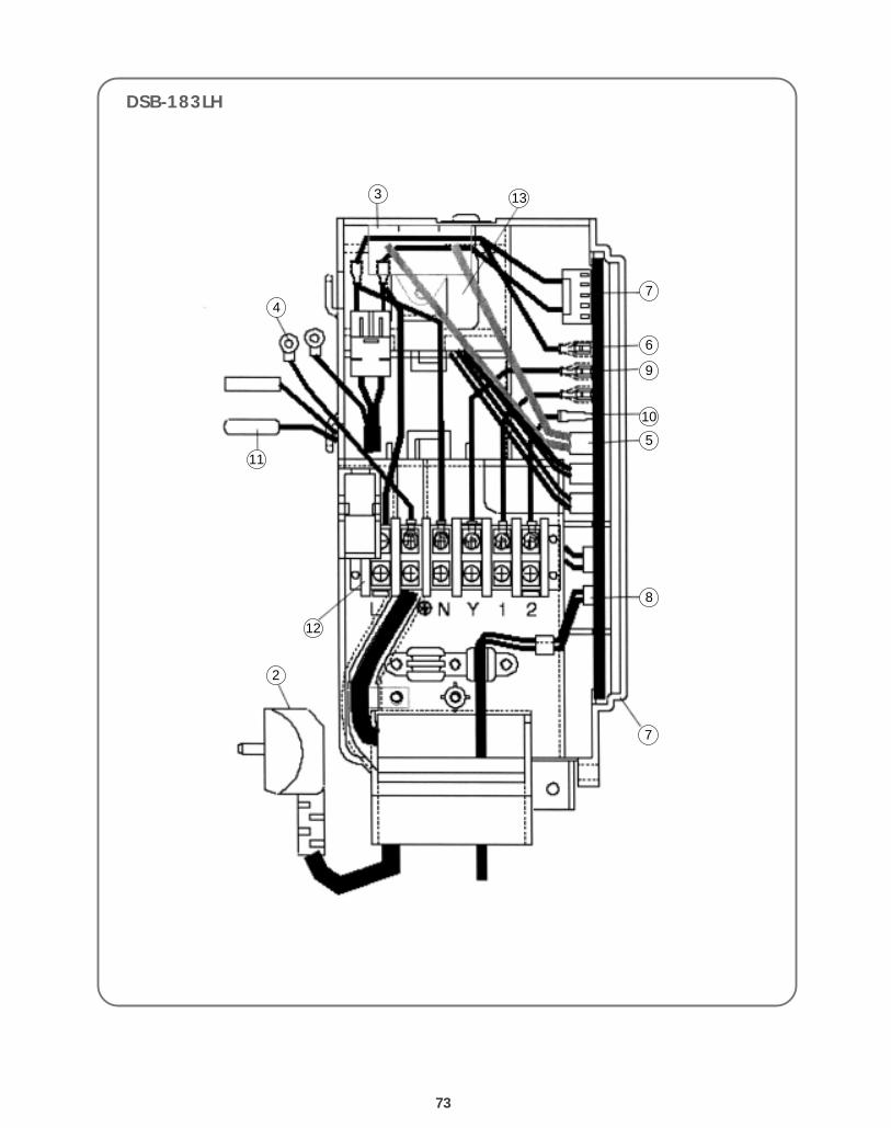
74
DSB-183LH
No PART CODE PART NAME Q'TY SPEC REMARK
13104300830
CONTROL PCB ASS’Y 1DSB-183LH-R/183LH/240LH-R
3104300770 DSA-183LH-R/240LH-R
2 3101395030 POWER CORD 1 250V/16A HO5UV-F 3x1.5mm2
3 3106902400 CAPACITOR SH.M.B 1 2.0MF 400V
4 3102797910 HARNESS EARTH 1 GREEN/YELLOW L170mm
5 3102714400 HARNESS CAPACITOR 1
6 3102704410 HARNESS COMP SIGNAL 1 UL1015#18
7 3102704010 HARNESS POWER 1 UL1015#16
8 3102702200 HARNESS TH3 1 TH-3-1
9 3102704430 HARNESS OD SIGNAL 1 UL1015#18
10 3102704420 HARNESS REVERSING V/ 1 UL1015#18
11 3104896300 SENSOR ID ASSY 1 NTM-KD43C-D2, L330
12 3108912320 TERMINAL BLOCK 1 SB-DBW-6P
13 5EPV050120 TRANSFORMER 1 DWA-220B
4 Caution: In this Service Manual, some parts can be changed for improving, their performance without notice in the parts list. So, if you need thelatest parts information, please refer to PPL(Parts Price List) in Service information Center(http://svc.dwe.co kr)

DEAWOO ELECTRONICS CO., LTD686, AHYEON-DONG MAPOGU,SEOUL, KOREA.C.P.O. BOX 8003 SEOUL KOREATELEX: DWELEC K28177-8CABLE:"DAEWOOELEC"FAX: +82-2-364-5588TEL: +82-2-360-7114, 8114http://www.dwe.daewoo.co.kr
S/M NO. : 3113907130 PRINTED DATE: MAY. 2001
Service ManualSplit System AirConditionerModel: DSB-093LH
DSB-183LH
DAEWOO ELECTRONICS Corp.
4 Caution: In this Manual, some parts can be changed for improving, their performance without notice in the parts list. So, if you need the latest parts information,please refer to PPL(Parts Price List) in Service Information Center (http://svc.dwe.co.kr).
S/M No. : 3113907130


![Daewoo Plasma Training Manual [ET]](https://img.pdfslide.us/doc/110x75/577d33bd1a28ab3a6b8b99c5/daewoo-plasma-training-manual-et.jpg)