Embed Size (px)
Citation preview

Control/Communicator D9412A&E Specifications
1.0 General.........................................................................................................31.1 Scope Of Work...................................................................................................................31.1.1 Introduction.......................................................................................................................31.1.2 Work included under this section.......................................................................................31.1.3 Related work specified under other sections of these specifications (Related sections)....31.2 General Conditions............................................................................................................31.2.1 Submittals at bid time.......................................................................................................31.2.2 Submittals after award of contract....................................................................................31.2.3 Documentation to be submitted by the Contractor upon completion of system installation
41.2.4 On-site security personnel training....................................................................................41.2.5 System approvals..............................................................................................................41.2.6 Quality assurance..............................................................................................................41.2.7 Warranty............................................................................................................................41.2.8 Service/Maintenance.........................................................................................................42.0 Products.......................................................................................................52.1 System Description............................................................................................................52.2 System Feature/Capability Summary.................................................................................62.3 System Interferance Requiremants...................................................................................92.4 Material.............................................................................................................................92.4.1 System Hardware Description:..........................................................................................93.0 Execution....................................................................................................153.1 Installation.......................................................................................................................153.2 Supervision......................................................................................................................153.3 Programming...................................................................................................................153.4 Testing.............................................................................................................................153.5 Commissioning................................................................................................................15

D9412
Notes:
D9412 A&E Specifications43957D Page 2 © 2002 Bosch Security Systems

D9412General
1.0 General1.1 Scope of Work1.1. IntroductionThe Contractor shall provide, install, and program a functionally complete, integrated Digital Alarm Communicator and Access Control System (DACS) per Manufacturer's guidelines, codes described, and these specifications.1.1. Work included under this sectionWORK INCLUDED IN CONTRACT SHALL BE INSERTED HERE. ITEMS TO BE INCLUDED UNDER THIS HEADING DEPEND UPON HOW A SPECIFIC PROJECT IS SCOPED AND PREFERENCES OF A PARTICULAR OWNER. THE FOLLOWING ARE USUALLY INCLUDED:
SYSTEM AND ITS COMPONENTS SYSTEM WIRING (LOW VOLTAGE) MOUNTING ACCESSORIES SYSTEM PROGRAMMING WARRANTY, SERVICE & TRAINING
1.1. Related work specified under other sections of these specifications (Related sections)RELATED WORK IN CONTRACT SHALL BE INSERTED HERE. ITEMS TO BE INCLUDED UNDER THIS HEADING DEPEND UPON HOW A SPECIFIC PROJECT IS SCOPED AND PREFERENCES OF A PARTICULAR OWNER. THE FOLLOWING ARE USUALLY INCLUDED:
POWER (120 VAC) RACEWAYS DOOR HARDWARE (ELECTRIC LOCKS) DOOR FRAME ALARM CONTACT PREPARATION TELEPHONE LINES (ONLY FOR OFF-SITE REPORTING)
1.2 General Conditions1.2. Submittals at bid time For bid evaluation, bid submittals shall include six (6) sets of the items described below:
Specification sheets (cut sheets) of all proposed equipment.Equipment list identifying:Model number of each unit.Quantities of each type of device.Unit costsSpecification compliance: A letter submitted with the bid, responding to specification sub-sections individually, indicating exceptions, substitutions, and alternates. The Contractor shall submit requests for substitutions (as well as all relevant technical data pertaining to the substituted equipment) to the specifier 10 days prior to the close of bid for evaluation and approval.
1.2. Submittals after award of contract1. These include point-to-point drawings of systems and wiring diagrams of individual
devices.2. Drawings: Shop drawings to provide details of proposed system and the work to be
provided. Permits: The Contractor shall be responsible for identifying requirements
D9412 A&E Specifications© 2002 Bosch Security Systems Page 3 43957D

D9412General
for permits from the local police department for the installation of the alarm system specified herein and shall assist the owner in obtaining the relevant alarm permits.
D9412 A&E Specifications43957D Page 4 © 2002 Bosch Security Systems

D9412General
1.2. Documentation to be submitted by the Contractor upon completion of system installation
1. "As-builts": Upon completion of installation, the Contractor shall prepare "as-built" drawings of the system. These "As-builts" shall be 30 in. x 42 in. format mylar reproducible drawings of each floor plan indicating exact device locations, panel terminations, cable routes and wire numbers as tagged and color-coded on the cable tag.
1. Additionally, final point-to-point wiring diagrams of each type of device (on 30 in. x 42 in. format) shall be included in the "as-builts."
2. "As-builts" shall be submitted to the Owner for approval prior to the system acceptance walk-through.
2. Operation and maintenance manuals: Three sets of operating manuals shall be provided explaining the operation and maintenance of the system.
1.2. On-site security personnel training Training in the complete operation of the systems shall be furnished by the Contractor upon completion of installation.THE EXTENT OF THE TRAINING PROCESS AND THE TIME NEEDED TO CARRY OUT THE TRAINING ARE DEPENDENT ON THE SIZE AND COMPLEXITY OF THE SYSTEM. SPECIFIER TO INSERT REQUIREMENTS FOR TRAINING HERE.1.2. System approvals
1. The system shall be the standard product of one manufacturer, and the manufacturer shall have been in business manufacturing similar products for at least 5 years.
2. After-sales support: The Contractor shall be a factory-authorized and trained dealer of the system and shall be factory-trained and certified to maintain/repair the system after system acceptance.
1.2. Quality assurance All equipment, systems, and materials furnished and installed under this section shall be installed in accordance with the applicable standards of:
1. National codes: NEC, NFPA, UBC2. Approvals and listings: UL (including Access Control)3. Local Authorities Having Jurisdiction
1.2. Warranty All components, parts, and assemblies supplied by the Manufacturers and installed by the Contractor shall be warranted against defects in material and workmanship for a period of at least 12 months (parts and labor), commencing upon date of acceptance by Owner. Warranty service shall be provided by a qualified factory-trained service representative.1.2. Service/Maintenance
1. System maintenance and repair of system or workmanship defects during the warranty period shall be provided by the Contractor free of charge (parts and labor).
2. Periodic testing of the system shall be carried out on a monthly or quarterly basis to ensure the integrity of the control/communicator, the sensing devices, and the telephone lines.
3. The installer shall correct any system defect within six hours of receipt of call from the Owner.
4. Extended service/maintenance agreements shall be offered by the Contractor for up to four years after the warranty expires. The agreement shall be renewable monthly, quarterly, or yearly.
D9412 A&E Specifications© 2002 Bosch Security Systems Page 5 43957D

D9412Products
2.0 Products2.1 System DescriptionThe DACS system specified herein shall include a Digital Alarm Communicator Transmitter (DACT), built-in telephone line monitor, 500 event (minimum) memory logger, real time clock, calendar, test timer, battery charging / voltage supervision circuitry, battery lead supervision, diagnostics displays, time / event-based scheduling system, lightning / EMI protection circuits, and the associated optional modules and components for a complete DACS system. Refer to section 2.4 Materials, p.10 for detailed hardware requirements and specifications.The DACT firmware shall support programmable "software" features as detailed in section 2.2 System Feature/Capability Summary, p.6. The following describes the general functional requirements of the DACS system:
A. The DACS shall support the connection and reporting of intrusion, fire detection and access control devices to a remote Digital Alarm Communicator Receiver (DACR).
B. The DACS shall provide identification, annunciation, and communication of alarmed detectors by point and each access control user by number.
C. The DACS shall be capable of segregating the points (i.e., a detector or group of detectors zoned together) into separate, independent "areas."
D. The DACS shall be "modularly" expandable using hard-wired address identification modules.
E. The DACS shall have electrically supervised detection loops and power supplies (mains and battery(s)). This supervision shall be programmable for the purposes of reporting this information to the DACR.
F. The DACS shall be capable of monitoring and switching to active telephone lines when trying to establish communications with the DACR and transmitting a report.
G. The DACS shall be capable of reporting and communicating alarm or trouble event data by reporting to one, two, three or four off-site remote DACRs via dial-up analog telephone lines.
H. The DACS shall be capable of sending (manually or automatically) test and status reports to remote DACRs.
I. The DACS shall be programmable locally or remotely. Programming shall be accomplished via a portable programmer or a computer running the Remote Account Manager (RAM) software. Users shall be capable of changing their own user passcode from the Alarm Command Center (ACC) and managers shall be capable of changing the user passcodes and authority assignments by area of other users from the ACC.
J. The DACS shall annunciate alarm, trouble, service reminders, and other relevant system status messages in custom English text at the ACC.
K. The DACS shall be capable of executing diagnostics and testing functions locally or remotely.
L. The DACS shall be capable of activating 128 relays and three additional outputs for auxiliary functions based on its classifications (area vs. panel wide).
M. The DACS shall be capable of controlling relays and automatically executing system functions based on a time / event scheduling program. The program can be hour, day of week or day of month based. Each scheduled event can be exclusive of one of four holiday date definitions that can include one to 365 selected Julian dates. The following functions can be executed:1. Arm / Disarm a specific area2. Bypass / Unbypass a point3. Activate / Deactivate a relay4. Send a test report5. Adjust system clock for daylight savings time6. Turn an Access Authority Level On / Off
D9412 A&E Specifications43957D Page 6 © 2002 Bosch Security Systems

D9412Products
7. Hold a Door Open (unlocked and shunted)8. Secure a Door Closed (locked, no valid cards will allow entry)9. Return a Door to Normal Operation (locked, valid cards will allow entry)10. Turn recording of Access Granted events On / Off (and transmittal if routing is ON)11. Turn recording of Access Denied events On / Off (and transmittal if routing is ON)
N. The DACS shall be capable of listening to calls answered by other devices on the premises side of the phone line and determining if a special tone is being sent from the incoming call (Remote Account Manager) and intercepting the call for Remote Account Manager sessions.
O. The DACS shall be capable of controlling up to eight separate doors using and providing entry to authorized users based on authority assigned to the user by the area into which the door enters. The DACS shall use not less than 24 bits of card/token specific data to identify the user. This card data shall not be truncated or shortened in making the identification of the user.
2.2 System Feature/Capability SummaryThe following indicates system software/hardware capabilities, capacities, and formats:
A. Number of Loops/Sensors: 246 separately identifiable points, of which 8 are on-board loops and 238 are off-board addressable points / zones connected to multiplexed backbone trunks. Each of the points shall be capable of supporting "group zoning." Group zoning refers to the combining of sensors into a separately identifiable and separately annunciated (programmable text) area.
B. Programming Point Functionality: Each point in the system shall provide for the following type of response in the system.1. Always on (24 hour response)2. On when the system is Master Armed3. Only on when the system is Perimeter Armed4. Displays / Does Not Display at the ACC when the point is activated5. Provides / Does Not Provide entry warning tone6. Sounds / Does Not Sound audible alarm indication7. The Point is bypassable / not bypassable8. Alarm Verification with programmable verification time9. Relay activation by Point10. Provides / Does Not Provide "watch point" capability11. Provides Swinger Bypass12. Defers Bypass Report13. Can return to the system after being force armed and then restoring14. Can return to the system after being bypassed and then restoring
C. Areas/Accounts: The DACS shall support 8 independent areas. Each of the eight areas shall have custom text associated with the armed state, disarmed state and point-off-normal state. Additionally, the DACS shall be capable of assigning 1 to 8 account identifiers to the areas depending on the distribution of areas per account. Each and all of the eight areas must be capable of Master and/or Perimeter arming (excluding predefined Interior protection).The DACS shall be capable of logically grouping 2 or more points into an area, or conversely, dividing the points into two or more areas. Any area shall be configurable to allow arming by specific users when a programmable number of devices are faulted or bypassed. Areas shall be independently controlled by their corresponding ACC. Each ACC can be designated to control a specific area, or group of areas, or all areas in the system. Independent control or relay functions by area shall be possible through programming assignments.
D9412 A&E Specifications© 2002 Bosch Security Systems Page 7 43957D

D9412Products
D. Number of Alarm Command Centers: 32 ACCs, each capable of displaying custom English text on vacuum fluorescent displays and sounding different patterns of audible alarm for different events, shall be required. Up to Eight ACCs can be supervised at one time. An ACC can be programmed to respond to the entry of any of the specifically authorized 250 user passcodes (followed by the [ENT] key) and cycle an assigned access control door using a connected door controller. The event is logged and transmitted (if routing is ON) to the DACR including door and user identity.
E. Number of User Passcodes: Up to 250 different passcodes shall be required. Each passcode shall be three to six digits (variable) and be assigned a 16-character user name that shall be printed on the local printer and DACR with associated opening and closing reports form the user. Passcodes shall be enabled or disabled by area(s) and shall be assigned one of fourteen different authority levels to carry out functions such as the activation of relays from the ACC. These passcodes shall also be required for carrying various system functions such as arming the system, disarming the system, transmitting a duress code, resetting the system and silencing sounders. A single user passcode shall be able to be used in each of the 8 areas with potentially a different authority level in each area.Each of the 250 different passcodes shall be able to be associated with 4 individual access cards/tokens. The authority of any of the four cards assigned to the user will be that of the user, but each card will report in the display, local printer, memory event log and at the DACR as a separate user / subuser number pair.
D9412 A&E Specifications43957D Page 8 © 2002 Bosch Security Systems

D9412Products
F. Number of Access Controlled Doors: Up to 8 doors, each connected to a door controller module that is subsequently connected to the DACT. Each door controller is programmed through the DACT from the local programmer or the RAM and can be configured independently from other doors. Each door contact is supervised and is wired to the door controller and can use normally open or normally closed contacts. The door lock can be programmed to reset the door strike time when the door either opens or closes. The door opening can terminate a programmable door buzzer. The door contact is shunted when valid access is being granted through the door. A request to exit and a separate request to enter supervised input is provided on the door controller. A programmable feature provides for door shunting on request to exit without activating the lock output. An optional buzzer can be sounded and an ACC can display a door closing warning if the door is held open beyond a programmable time. The door can be programmed to activate an alarm or trouble in the door left open condition. The DACS shall be capable of transmitting the Door Left Open indication to the DACR. The door strike shall be capable of being programmed to automatically unlock if the area is completely disarmed and will not automatically unlock if the area is selectively disarmed. The DACS shall be capable of being programmed, on a time basis, to record access granted and or access denied events by door.
G. Access Control / User Features: The DACS shall allow each authority profile to specify whether users holding that authority are to be granted access into the area based on whether the area is completely disarmed, perimeter armed or completely armed. Additionally, the DACS shall be able to automatically disarm the area or convert the arm state of the area from fully armed to perimeter armed based on the authority level assigned to the user and area. Assigned users shall be able to manually control the door from an ACC by setting the door to Normal Operation, Manually Locked or Secured (valid cards will not operate).
H. Communication Formats: The Bosch Security Systems Modem IIIa2 ™ communications format shall be utilized for optimum system performance. The DACT shall report to a Commercial Central Station using a Bosch Security Systems D6500 Alarm Receiver that supports the Bosch Security Systems Modem IIIa2 ™ communications format. One such advantage is point identification information transmission to DACRs (Alarms, Troubles and Restorals by point). Others include actual point number; point text; actual user number, user name; by-passed points; relay activation; opening/closing reports by users; late, early, or fail opening/closing reports, and opening/closing reports by area.
I. Testing, Diagnostic, and Programming Facilities: Automatic test reports and remote system access for diagnostics, programming, and log (Logger) uploads shall also be supported via a remote central station computer utilizing the RAM software.
J. Logger Capacities and Formats: 500 events (minimum) indicating time, date, type of event, account number, area number, user ID, point text, user text and primary/secondary event route each event. Logs shall be viewed locally at the ACC and remotely via an upload to a computer running the RAM software. The DACS shall also support the printing of these events on up to three local printers. The DACS shall also send a report to the DACR when the log reaches a programmable "percent full capacity" so that RAM can retrieve the stored events. Events can be routed to specific printers by group, signal type and area.
K. Reports: Reports to DACRs at commercial central stations as a result of system supervision shall include alarm, trouble, missing modules, restoral, system status, AC failure and low battery. The DACS shall also transmit test reports once every 24 hours. CPU failure shall be annunciated locally. The ACCs should display the following information for the indicated system supervisory conditions:
1. Call for Service2. Service Panel
3. Service ParamD9412 A&E Specifications
© 2002 Bosch Security Systems Page 9 43957D

D9412Products
4. Service AC Fail5. Service Battery Low6. Service Battery Missing7. Service Communications Failure8. Service Keypad9. Service Route 10. Service Printer11. Service Point Buss Failure
D9412 A&E Specifications43957D Page 10 © 2002 Bosch Security Systems

D9412Products
L. Telephone Lines and "Phone Routing": The DACS shall support two (2) telephone lines that are to be alternated for the transmission of consecutive events. The DACS shall have the capability of communicating with up to four different DACRs (phone numbers), Each Phone Number can be up to 24 digits long. The DACS reports shall be classified, by event, into one or more of four routing groups. Each routing group can specify a DACR to be designated as a primary and another DACR as back-up. Assigning an event to multiple routing groups provides for duplicate destination for the event. The transmission of events, allows the reporting of different types of information to different remote DACRs.
M. Number of Programmability of Relay Output Modules: Eight relays (Form C) are to be provided per octo-relay module for a total of 128 relays plus three additional outputs per DACS. These multi-purpose modules are programmable and shall be used to implement auxiliary functions (manually or automatically).Relays and other outputs may be programmed to follow up to 14 different area conditions or up to 12 panel conditions. Relays may also be programmed to follow individual points or groups of points.
N. Number and Alarm Output Selections: Four different types of alarm output selections shall be supported by the DACS: Steady, Pulsed, California Standard, and Temporal Code 3.The system can be configured to provide zoned indication of alarm conditions.
O. Miscellaneous Features: Programmable alarm output timer, 31 programmable entry delay times, exit delay programmable by area, individually programmable point of protection text, point bypassing, and keyswitch arming capability with LED outputs.
P. Real-Time Clock, Calendar, and Test Timer: The DACS shall incorporate an integral real-time clock, calendar, and a test timer.
Q. Opening and Closing Windows: The system shall be programmed with "normal" opening and closing periods for each day of the week and thus suppress scheduled opening / closing reports and report only the exceptions, i.e., opening / closing outside the pre-defined time window. The DACS shall have the capability to suppress opening / closing reports, overriding the programmed open / close windows during holidays and automatically arming the DACS (by area) at the end of the closing period.
R. DACS Power Ratings: The DACS shall provide 1.4 amps of auxiliary power and 2 amps of alarm power, both rated at 12 VDC. Additional auxiliary power shall be provided by adding battery/charger modules up to a maximum of 2 amps.
S. DACS Fault Detection: The DACS shall check the point sensor loops once every 300 milliseconds. The point response time is programmable over a range of 300 milliseconds to 4.5 seconds.
T. User-Programmable Features: The DACS shall provide a "user-friendly" interface for programming / customizing the system to the operational criteria of the application. The DACS shall be capable of being operated via:1. The Command Structure2. Menu / Command List
U. These system features shall have restrictions based on fourteen individually programmable levels of passcode authority that can be assigned to system users. The user's passcode shall have the capability of being assigned a different authority level in each of the eight areas. A service passcode can be assigned to the servicing agent allowing the agent limited access to system functions. User-programmable / activated functions include:1. Arming the system: All areas, specific area(s) only, perimeter instant, perimeter
delayed, perimeter partial, watch mode, and arming the system with a duress passcode.
3. Disarming the system: All areas, specific area(s) only and disarming with a duress passcode.
D9412 A&E Specifications© 2002 Bosch Security Systems Page 11 43957D
D9412Products
4. Viewing system status: Faulted points, event memory, bypassed points, area status and point status.
5. Implementation functions: Bypass a point, unbypass a point, reset sensors, silence bell, activating relays, initiating the remote programming function locally to allow programming the system from a remote location. The ACCs can also be temporarily readdressed to view the status of a remote area.
6. Testing the system: Local Walk test, Service Walk test, Fire test, send report to remote DACR to check the telephone link, and programming the time and date for the next test report transmission.
7. Change system parameters: ACC display brightness, system time and date, and add/delete/change passcodes.
8. Extend the closing time of system.9. Transmitting special alerts and activating audible and visible signals.10. Executing multiple commands / ACC keystrokes from a single Menu / Command
List item. This function shall be able to have a 16 character (alphanumeric) title to identify it on the ACC display.
11. Editing of time / event based scheduling program from the ACC.12. The DACS shall also provide a "service menu" to implement functions such as
viewing and printing the system log, displaying the system firmware revision number, and defaulting (toggling) text displays between custom and default text displays for troubleshooting.
2.3 System Interface RequirementsA. Grounding: The Contractor shall properly earth ground the DACS to prevent
electrostatic charges and other transient electrical surges from damaging the DACS panel.
B. Primary power: The Contractor shall provide a dedicated 120 VAC power circuit to the DACS system. This circuit shall be connected to the emergency power system. The 120 VAC is stepped down to 16.5 VAC to power the DACS panel using a class two, plug-in transformer. This power circuit shall be properly rated to continuously power all points and functions indefinitely in full alarm condition.
C. Primary power supervision: When the primary power source fails, the system can be configured to report an "AC Fail" message to a commercial central station. The transmission delay of this message is programmable from one to ninety seconds. The message can also be programmed to "tag-along" with another message transmitted to the central station. The system will always display a loss of primary power on the ACC and may be configured to provide additional audible warning.
D. Secondary power (standby battery): The Contractor shall provide adequate battery power as defined by the relevant application criteria, (UL 865 and 985 for alarm installations or NFPA 72 chapters for fire applications). Appropriate battery chargers shall be provided consistent with the battery back-up capacity.
E. Secondary power supervision: When the secondary power source experiences a 85% depletion of its standby capacity, the system can be configured to report a "Low Battery" message to a commercial central station. The system will always display a low battery condition on the ACC and may be configured to provide additional audible warning.
F. Wiring: The contractor shall provide cables consistent with the manufacturer's recommendations. The following general guidelines shall be followed for wiring installation:1. Wiring shall be appropriately color-coded with permanent wire markers. Copper
conductors shall be used.2. All signal cables provided under this contract shall be Class II, plenum-rated cable
where required. Where subject to mechanical damage, wiring shall be enclosed in metal conduits or surface metallic raceway.
D9412 A&E Specifications43957D Page 12 © 2002 Bosch Security Systems

D9412Products
3. Data wires shall not be enclosed in conduit or raceways containing AC power wires.
4. Where EMI may interfere with the proper operation of the DACS circuits, twisted/shielded cable shall be used.
G. The DACS system shall be protected from EMI and lightning surges.H. Telephone interface: The DACS shall be equipped with a phone line monitor and shall
interface with the phone lines via RJ-31X jacks for supervision of the telephone line connection to the DACS panel. When a telephone line is determined to be out of service by the DACS panel, the event will be annunciated locally on the ACC and transmitted to the central station. The transmission delay of this message is programmable from ten to two hundred forty seconds. A telephone line switching modules shall be used to interface to a second telephone line. This interface shall conform with FCC rules part 15 and 68.
I. Auxiliary function control interfaces: Auxiliary functions such as activating bells, strobes, or lights shall be accomplished using the optional relay modules. These auxiliary interfaces shall be electrically isolated to avoid inter-system interferences or damages.
J. Functional criteria programmed into system memory shall be backed up by battery power. Additionally, the number of system programmers shall be severely restricted via the use of program locking features and passwords.
2.4 Materials2.4. System Hardware Description:
A. DACS System: The DACS shall be provided, at minimum, with the following components. Additional accessories shall be provided based on the quantities and features required for the application.1. Enclosure2. Lock and key3. D9412 DACT with removable terminal blocks and single crew mounting bracket4. Faceplate shield and metal bracket covering rear of D9412 circuit assembly5. Power transformer6. Manuals
D9412 A&E Specifications© 2002 Bosch Security Systems Page 13 43957D

D9412ProductsThe DACS system control panel shall be Bosch Security Systems D9412.SPECIFIER TO LIST TYPES AND QUANTITIES OF ACCESSORIES REQUIRED FOR THE APPLICATION. ITEMS AND DESCRIPTIONS WHICH ARE LISTED BELOW AND ARE NOT RELEVANT TO YOUR APPLICATION SHOULD BE DELETED
B. System Accessories:1. D56: Alarm Command Center surface conduit backbox (D56R is red)2. D57: Alarm Command Center conduit backbox (for D269 only)3. D101F: Fire lock and key4. D125B: Class "B" loop module - Dual Powered loop interface module - two
separate powered loops for 12 or 24 VDC, 2-wire devices5. D127: Reversing relay module. Reports two separate alarms at DACR.
Required for UL-certified mercantile and bank burglar alarm systems applications
6. D129: Class "A" loop module - Dual class A, 4-wire initiating circuits. Module shall detect alarm in the presence of a single open or ground fault in the circuit. Each circuit shall have adjustable "alarm retard" and alarm reset delay
7. D130: Relay module 5 amps, Form C8. D136: Plug-in relay, 2 amps @ 30 VDC. This relay is required for various
functions such as ground start telephone system application and auxiliary power reset
9. D268: UL independent zone control module10. D269: UL independent zone control keypad11. D9412: D9412 circuit board mounted on steel mounting skirt and
literature pack12. D811: Arm status relay module. Form C relay, activated based on
information transmitted on the serial output13. D8103: Universal enclosure14. D8108A: UL attack-resistant enclosure15. D8109: UL fire enclosure16. D8121A: STU - Works with Base Ten Telecom, Inc. VerSuS®-derived channel
receiving system to provide alarm and critical event reporting as well as telephone line supervision
17. D8122: UL-listed version of D8121A18. D8125: Point of Protection EXpander module. Each POPEX (up to two per
system) shall monitor up to 119 model D9127 Point of Protection Input Transponders "POPIT” or Integrated Fire or Intruder Alarm detectors
19. D9127T: POPIT module - tampered, UL-listed for fire20. D9127U: POPIT module - untampered UL-listed for fire21. D8128C: Octo-POPIT module – combines POPEX and POPIT functions and
provides 8 points to each DACS. A total of 30 OctoPOPITS per DACS
22. D8129: Octo-relay module - 8 programmable dry contact relay outputs, "Form C." Uses information on DACT serial data output to selectively activate the relay outputs
23. D8130: UL release module – designed for release applications commonly found in NFPA 72, chapter 6, fire alarm installations such as fire
D9412 A&E Specifications43957D Page 14 © 2002 Bosch Security Systems

D9412Products
door release, elevator recall, emergency door unlock, stairwell pressurization, smoke exhaust control and HVAC control. Two independent Form C contacts, each rated at 5 amps. Multiple D8130s can be connected in parallel to a DACT.
24. D9131A: Parallel printer interface – provides Centronics standard parallel output to be used for a parallel printer. 80 character format.
25. DS835: PIR/Microwave Detector, 35 ft. (11 m)26. ZX835: PIR/Microwave Detector, 35 ft. (11 m), with built-in POPIT27. DS970: PIR/Microwave Detector, 70 ft. (21 m)28. ZX970: PIR/Microwave Detector, 70 ft. (21 m), with built-in POPIT29. DS934: PIR Detector, 35 ft. (11 m)30. ZX935Z: PIR Detector, 35 ft. (11 m), with built in-POPIT31. DS775: PIR Detector, 50 ft. (15 m)32. ZX776Z: PIR Detector, 50 ft. (15 m), with built-in POPIT33. DS794Z: PIR Detector, 80 ft. (24 m) / 200 ft. (61 m) (120 ft. [37 m] with
optional lens)34. ZX794Z: PIR Detector, 80 ft. (24 m) / 200 ft. (61 m) with built-in POPIT (120
ft. [37 m] with optional lens)35. DS938Z: Ceiling Mount PIR Detector, 60 ft. (18 m)36. ZX938Z: Ceiling Mount PIR Detector, 60 ft. (18 m), with built-in POPIT37. DS150i: Request to Exit Detector (DS151i in grey color)38. DS1101i: Glass Breakage Detector, 25 ft. (8 m)
C. Power Supply:1. D122: Dual battery harness2. D126: Sealed lead-acid battery, 7 AH3. D1218: Sealed lead-acid battery, 18 AH4. D1640: Transformer, 16.5 VAC, 40 VA5. D8132: UL - 12V auxiliary battery charger. Combined with external
batteries, increases standby time and provides additional power to auxiliary outputs of D9412B.
6. D8004: UL transformer enclosureD. Telephone Accessories:
1. D928: Dual telephone line module – Alternates event transmission to Central Station between primary and secondary phone lines. Transmits over other phone line when first phone line is determined to be inoperable. Periodically tests phone line for usage and integrity and reports to central station when phone line is faulty. Remembers faulty line and transmits over operational line.
2. D161: 8 ft. (2.4 m) phone cord3. D162: 2 ft. (61 cm) phone cord
E. Fire Initiating Devices and Accessories:1. D254: Heat Detector Head, 135º (uses D271S, D261A)2. D255: Heat Detector Head, 190º (uses D271S, D261A)3. D261A: Smoke Base, 12 V, 2 wire, 6 inch (15 cm)4. D261W: Smoke Base, 12 V, 2 wire, 6 inch (15 cm), white
D9412 A&E Specifications© 2002 Bosch Security Systems Page 15 43957D

D9412Products
5. D262: Smoke Detector Head, Photoelectric, (uses D261A, D271S)6. D263: 2 wire, Direct Wire, Photoelectric Smoke Detector7. D263TH: 2 wire, Direct Wire, Photoelectric Smoke Detector / 135º Heat8. D265W: Smoke Detector Head, Photoelectric, white (uses D261W, D271W)9. D266W: Smoke Detector Head, Photoelectric, 135º Heat (uses D261W,
D271W)10. D271S: Addressable Smoke Base, 12 V, 6 inch (15 cm)11. D271W: Smoke Base, 12 V, 4 wire, 6 inch (15 cm)12. D273: 4 wire, Direct Wire, Photoelectric Smoke Detector13. D273TH: 4 wire, Direct Wire, Photoelectric Smoke Detector, 135º Heat14. D275: Power Supervision Module (12 V or 24 V)15. D285: Smoke Detector Head, Photoelectric (uses D287, D288, D292,
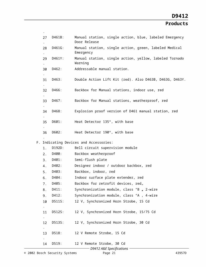
D293)16. D285TH: Smoke Detector Head, Photoelectric, 135º Heat17. D287: Smoke Base, 12 V, 2 wire, 5.5 inch (14 cm)18. D288: Smoke Base, 12 V, 2 wire, 6 inch (15 cm)19. D289: Smoke Base, 12 V, 4 wire, 6 inch (15 cm)20. D292: Smoke Base, 12 V, 4 wire, 6 inch (15 cm)21. D293A: Smoke Base, 12 V, 4 wire, 6 inch (15 cm), w/relay22. D293E: Smoke Base, 12 V, 4 wire, 6 inch (15 cm), w/power supervision23. D293S: Smoke Base, 12 V, 4 wire, 6 inch (15 cm), w/sounder24. D296: 24 V, Projected Beam Smoke Detector25. D297: 12 V, Projected Beam Smoke Detector26. D461: Manual station - single action, red27. D461B: Manual station, single action, blue, labeled Emergency Door
Release28. D461G: Manual station, single action, green, labeled Medical Emergency29. D461Y: Manual station, single action, yellow, labeled Tornado Warning30. D462: Addressable manual station.31. D463: Double Action Lift Kit (red). Also D463B, D463G, D463Y.32. D466: Backbox for Manual stations, indoor use, red33. D467: Backbox for Manual stations, weatherproof, red34. D468: Explosion proof version of D461 manual station, red35. D601: Heat Detector 135º, with base36. D602: Heat Detector 190º, with base
F. Indicating Devices and Accessories:1. D192D: Bell circuit supervision module2. D400: Backbox weatherproof3. D401: Semi-flush plate4. D402: Designer indoor / outdoor backbox, red5. D403: Backbox, indoor, red6. D404: Indoor surface plate extender, red7. D405: Backbox for retrofit devices, red
D9412 A&E Specifications43957D Page 16 © 2002 Bosch Security Systems

D9412Products
8. D411: Synchronization module, class “B”, 2-wire9. D412: Synchronization module, class “A”, 4-wire10. D511S: 12 V, Synchronized Horn Strobe, 15 Cd11. D512S: 12 V, Synchronized Horn Strobe, 15/75 Cd12. D513S: 12 V, Synchronized Horn Strobe, 30 Cd13. D518: 12 V Remote Strobe, 15 Cd14. D519: 12 V Remote Strobe, 30 Cd15. D521: 12 V Remote Strobe, 15/75 Cd16. D425A: 12 V, Semi-Flush, Multi-Tone, Horn/Strobe, 30 Cd17. D433A: 12 V, Semi-Flush, Multi-Tone, Horn/Strobe, 15 Cd18. D475A: 12 V, Semi-Flush, Multi-Tone, Horn/Strobe, 15/75 Cd19. D457: 12 V / 24 V Horn, Multi-Tone20. D470: 12 V / 24 V, Semi Flush Prioritized Input Horn21. D472A: 12 V, Semi Flush Prioritized Input Horn / Strobe, 15 Cd22. D476A: 12 V, Semi Flush Prioritized Input Horn / Strobe, 15/75 Cd23. D440: 12 V, Motor Bell, 6 inch (15 cm) shell24. D442: 12 V, Motor Bell, 10 inch (25 cm) shell25. D428A: 12 V, Mini Horn/Strobe, 30 Cd26. D450A: 12 V, Mini Horn/Strobe, 15 Cd27. D448: 12 V, Mini Horn28. D448W: 12 V, Mini Horn, white29. D471A: 12 V, Mini Horn/Strobe, 15/75 Cd
G. Annunciation Devices:1. D1255: Alarm Command Center (ACC) - Built-in multi-tone sounder.
Displays status in custom English text on 16-character display. If more than 4 ACCs are required, add D8132 battery charger unit. ACCs provide "command menu" user interface. ACC can be supervised. Model D1255R for red color, D1255W for white.
2. D720: Area LED annunciator with keypad. For use within an area for up to 8 protected points of annunciation.
3. D1256: Alarm Command Center ACC) - Built-in multi-tone sounder. Displays status in custom English text on 16 character display. Used for display and control of fire areas only.
4. D1257: Remote Fire Alarm Annunciator. Red plastic for use in public areas. Displays status in custom English text on 16 character display. Does not provide system control.
H. Access Control Devices:1. D9210B: Door Controller. Connects one door to the DACT via the 4-wire
SDI / Keypad bus.2. D8201: Proximity Key Reader (black), available as D8201W (white)3. D8203: Mullion Proximity Key Reader (black), available as D8203W (white)4. D8221: Sensor Weigand Swipe Card Reader (black)5. D8222: Sensor Wiegand Key Reader (black)6. D8223: HID Proximity Reader (black)7. D8224: HID Mini Proximity Reader (black)
D9412 A&E Specifications© 2002 Bosch Security Systems Page 17 43957D

D9412Products
8. D8227: Magnetic Stripe Insert Card Reader (matches D1255)9. D8229: Wiegand PIN Keypad (stainless steel)10. D8230-25: Cards for D8227 Reader, 25/pk11. D8240-25: Cards for D8227 Reader, Photo ID type, 25/pk12. D8231-10: Cards for D8221 Reader, 10/pk13. D8241-10: Cards for D8221 Reader, Photo ID type,10/pk14. D8232-10: Keys for D8222 Reader, 10/pk15. D8236-10: Cards for D8223 and D8224 Reader, 10/pk16. D8238-10: Proximity Keys for D8201 and D8203 Readers, 10/pk17. D8239-10: Proximity Cards for D8201 and D8203 Readers, 10/pk
D9412 A&E Specifications43957D Page 18 © 2002 Bosch Security Systems

D9412Products
Notes:
D9412 A&E Specifications© 2002 Bosch Security Systems Page 19 43957D

D9412Execution
3.0 Execution3.1 InstallationInstall all equipment and materials in accordance with the "current" recommendations of the manufacturer. The work shall also be in accordance with:
A. Installation criteria defined in these specifications and in the construction documents.B. Approved submittals.C. Applicable requirements of referenced standards.
3.2 SupervisionThe contractor shall provide the following services as part of the contract:
A. Supervision of sub-contractors.B. Coordination of other contractors for system-related work (electrical contractor, finish
hardware contractor, architect, and general contractor).C. Attending site construction/coordination meetings.D. Keeping updated construction drawings at the construction site.E. Meeting construction deadlines per the construction schedule.
3.3 ProgrammingProgramming of the system shall include the following tasks:
A. Programming system configuration parameters (hardware and software, zone/circuit numbers, communication parameters).
B. Programming operational parameters such as opening/closing reports and windows, system response text (custom English) displays of events, activation of relays that drive auxiliary devices, and identifying types of zones/loops.
C. Programming passcodes according to the authorities and functions defined by the owner.
D. Other system programming tasks required by the owner. These additional programming requirements shall be coordinated between the owner and the contractor.
3.4 TestingA. Operational Testing: The contractor shall perform thorough operational testing and
verify that all system components are fully operational.B. Hard-copy System Printout: The contractor shall submit a hard-copy system printout
of all components tested and certify 100 percent operation indicating all devices/panels/units have passed the test criteria set forth by the manufacturer.
C. Acceptance Test Plan Form: An acceptance test plan form shall be prepared/provided by the contractor prior to the acceptance walk-through.
This form shall include separate sections for each device/panel/unit as well as a column indicating the manufacturer's performance allowance/margin, a column indicating the result of the testing performed by the contractor (pass/fail), and an empty column for recording findings during the walk-through.3.5 CommissioningThe contractor shall certify completion in writing and schedule the commissioning walk-through. The contractor shall provide all the tools and personnel needed to conduct an efficient commissioning process.
D9412 A&E Specifications43957D Page 20 © 2002 Bosch Security Systems
D9412Execution
D9412 A&E Specifications© 2002 Bosch Security Systems Page 21 43957D

© 2002 Bosch Security Systems130 Perinton Parkway, Fairport, NY 14450-9199 USACustomer Service: (800) 538-5807
43957DA&E Specifications
10/02D9412
Page 22 of 16