Embed Size (px)
DESCRIPTION
year 1 building syrveying uni cw
Citation preview
DEPARTMENT OF PROPERTY AND CONSTRUCTION
BUILDING STRUCTURES A
CW1: ‘TIMBER & STEEL BEAM DESIGN’
DAVID ARMITAGE
BY;SHOAYB PATELI.D: 03094761
INTRODUCTION
Building Structures A Shoayb PatelCw1: ‘Timber & Steel Beam Design’ I.D: 03094761
‘A timber floor consists of 60 x 220 C16 joists @ 395mm centres and supports a load of 2.5 kN/sq.m (1.0, DL, 1.5 LL) over a span of 4.6m’.
1) The purpose of this assignment is to determine whether or not the joists are adequate and if not, suggest solutions both (a) using the existing joists and (b) replacing them with new joists.
In order to assess the above the following will have to be carried out:
Calculate the Section Modulus (Z) value required for the joist in order for it to be adequate to support the load.
Calculate the Moment of Inertia (I) value required for the joist in order for it to be adequate to support the load.
Calculate the Section Modulus (Z) of the 60 x 220 C16 joist.
The Moment of Inertia value of the 60 x 220 C16 joist.
The required values are evaluated against those of the 60 x 220 C16 joist, and we can determine whether the joists are adequate.
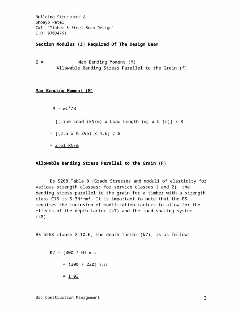
Section Modulus (Z) Required Of The Design Beam
Z = Max Bending Moment (M) Allowable Bending Stress Parallel to the Grain (f)
Max Bending Moment (M)
M = wL²/8
= [(Line Load (kN/m) x Load Length (m) x L (m)] / 8
= [(2.5 x 0.395) x 4.6] / 8
= 2.61 kN/m
Allowable Bending Stress Parallel to the Grain (F)
Bsc Construction Management 2
Building Structures A Shoayb PatelCw1: ‘Timber & Steel Beam Design’ I.D: 03094761
Bs 5268 Table 8 (Grade Stresses and moduli of elasticity for various strength classes: for service classes 1 and 2), the bending stress parallel to the grain for a timber with a strength class C16 is 5.3N/mm². It is important to note that the BS requires the inclusion of modification factors to allow for the effects of the depth factor (k7) and the load sharing system (k8).
BS 5268 clause 2.10.6, the depth factor (k7), is as follows:
K7 = (300 / H) 0.11
= (300 / 220) 0.11
= 1.03
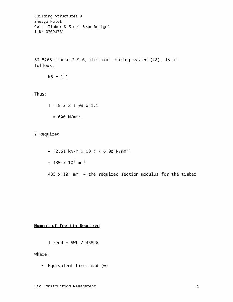
BS 5268 clause 2.9.6, the load sharing system (k8), is as follows:
K8 = 1.1
Thus:
f = 5.3 x 1.03 x 1.1
= 600 N/mm²
Z Required
= (2.61 kN/m x 10 ) / 6.00 N/mm²)
= 435 x 10³ mm³
435 x 10³ mm³ = the required section modulus for the timber
Moment of Inertia Required
Bsc Construction Management 3
Building Structures A Shoayb PatelCw1: ‘Timber & Steel Beam Design’ I.D: 03094761
I reqd = 5WL / 438eδ
Where:
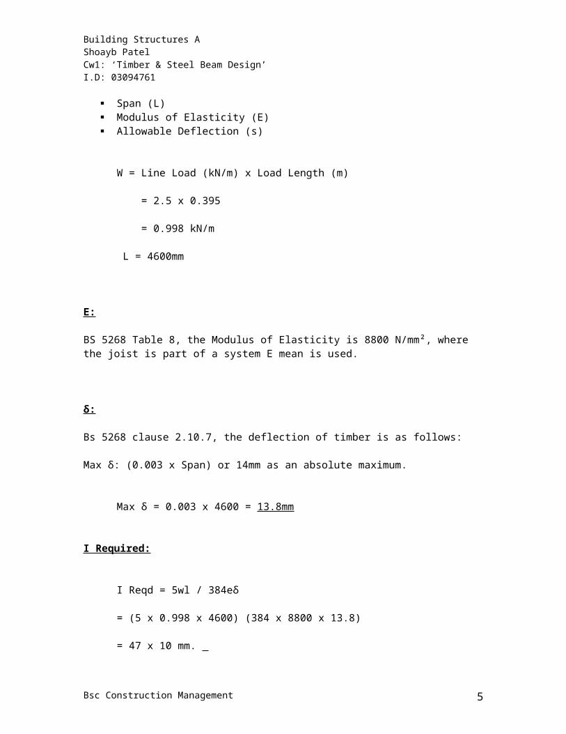
Equivalent Line Load (w) Span (L) Modulus of Elasticity (E) Allowable Deflection (s)
W = Line Load (kN/m) x Load Length (m)
= 2.5 x 0.395
= 0.998 kN/m
L = 4600mm
E:
BS 5268 Table 8, the Modulus of Elasticity is 8800 N/mm², where the joist is part of a system E mean is used.
δ:
Bs 5268 clause 2.10.7, the deflection of timber is as follows:
Max δ: (0.003 x Span) or 14mm as an absolute maximum.
Max δ = 0.003 x 4600 = 13.8mm
I Required:
I Reqd = 5wl / 384eδ
= (5 x 0.998 x 4600) (384 x 8800 x 13.8)
= 47 x 10 mm.
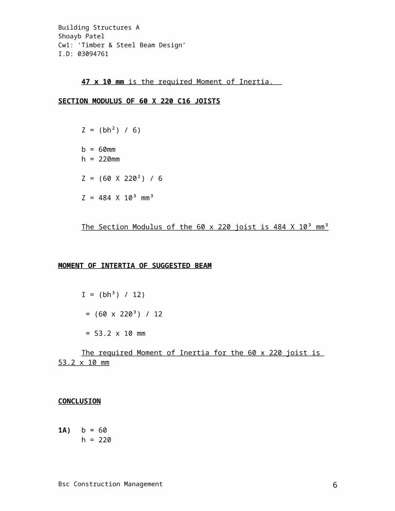
47 x 10 mm is the required Moment of Inertia.
SECTION MODULUS OF 60 X 220 C16 JOISTS
Bsc Construction Management 4
Building Structures A Shoayb PatelCw1: ‘Timber & Steel Beam Design’ I.D: 03094761
Z = (bh²) / 6)
b = 60mmh = 220mm
Z = (60 X 220²) / 6
Z = 484 X 10³ mm³
The Section Modulus of the 60 x 220 joist is 484 X 10³ mm³
MOMENT OF INTERTIA OF SUGGESTED BEAM
I = (bh³) / 12)
= (60 x 220³) / 12
= 53.2 x 10 mm
The required Moment of Inertia for the 60 x 220 joist is 53.2 x 10 mm
CONCLUSION
1A) b = 60h = 220
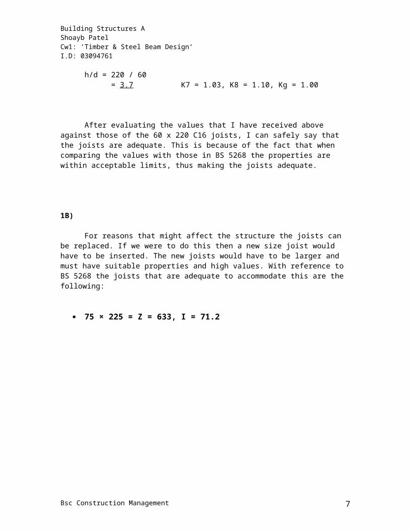
h/d = 220 / 60 = 3.7 K7 = 1.03, K8 = 1.10, Kg = 1.00
After evaluating the values that I have received above against those of the 60 x 220 C16 joists, I can safely say that the joists are adequate. This is because of the fact that when comparing the values with those in BS 5268 the properties are within acceptable limits, thus making the joists adequate.
1B)
Bsc Construction Management 5
Building Structures A Shoayb PatelCw1: ‘Timber & Steel Beam Design’ I.D: 03094761
For reasons that might affect the structure the joists can be replaced. If we were to do this then a new size joist would have to be inserted. The new joists would have to be larger and must have suitable properties and high values. With reference to BS 5268 the joists that are adequate to accommodate this are the following:
75 × 225 = Z = 633, I = 71.2
Bsc Construction Management 6
Building Structures A Shoayb PatelCw1: ‘Timber & Steel Beam Design’ I.D: 03094761
2.) In order to produce the Shear Force Diagram and Bending Moment Diagram, both the reactions and bending moments have to be calculated.
The diagram below shows the floor loads being distributed along the beam in the form of line loads and also the wall loads being transferred to the beam in the form of point loads.
The line loads for the three floor loads will be calculated as follows:
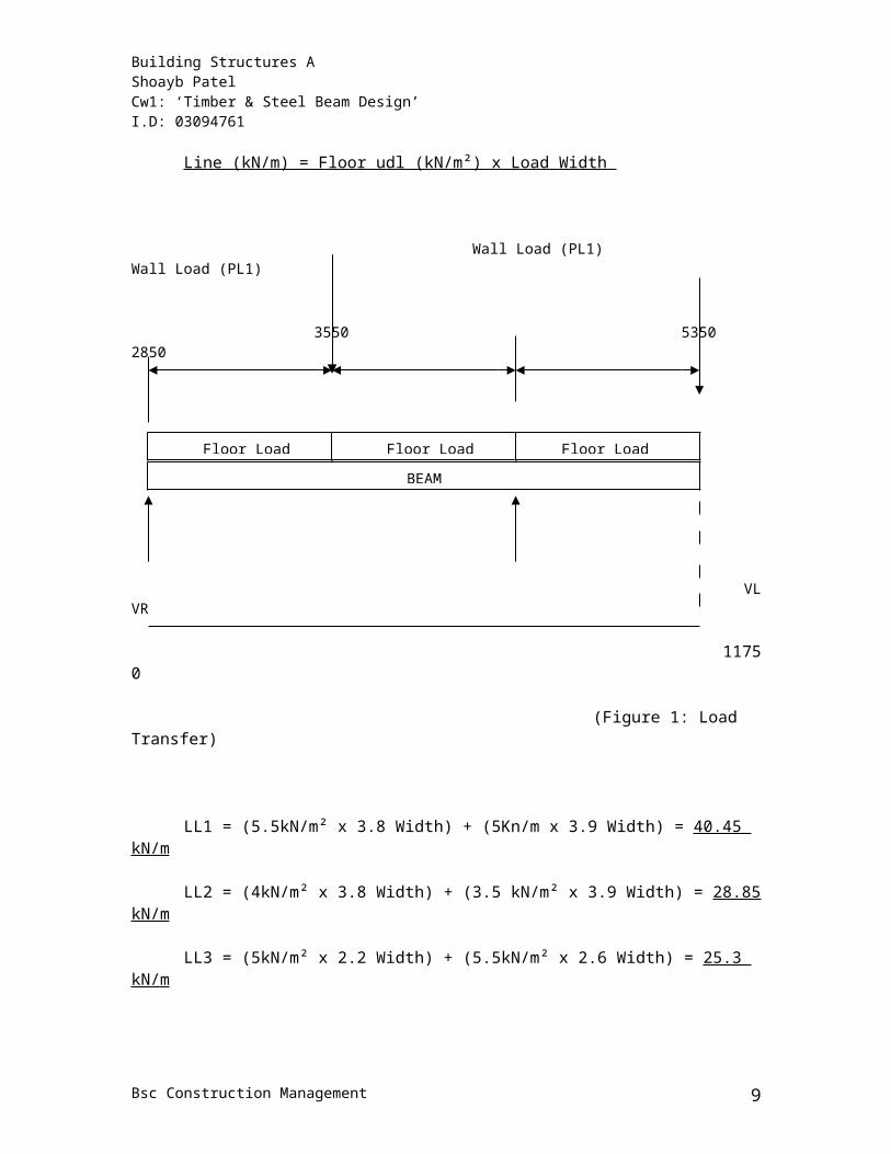
Line (kN/m) = Floor udl (kN/m²) x Load Width
Wall Load (PL1) Wall Load (PL1)
3550 5350 2850
VL VR
11750
(Figure 1: Load Transfer)
LL1 = (5.5kN/m² x 3.8 Width) + (5Kn/m x 3.9 Width) = 40.45 kN/m
LL2 = (4kN/m² x 3.8 Width) + (3.5 kN/m² x 3.9 Width) = 28.85 kN/m
LL3 = (5kN/m² x 2.2 Width) + (5.5kN/m² x 2.6 Width) = 25.3 kN/m
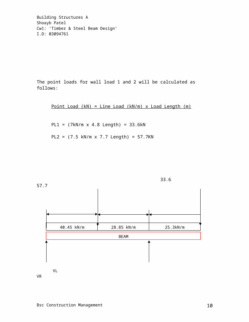
The point loads for wall load 1 and 2 will be calculated as follows:
Bsc Construction Management 7
Floor Load (LL1) Floor Load (LL2) Floor Load (LL3)
BEAM
Building Structures A Shoayb PatelCw1: ‘Timber & Steel Beam Design’ I.D: 03094761
Point Load (kN) = Line Load (kN/m) x Load Length (m)
PL1 = (7kN/m x 4.8 Length) = 33.6kN
PL2 = (7.5 kN/m x 7.7 Length) = 57.7KN
33.6 57.7
VL VR (Figure 2: Downward Forces)
REACTION CALCULATIONS
Bsc Construction Management 8
40.45 kN/m 28.85 kN/m 25.3kN/m
BEAM
Building Structures A Shoayb PatelCw1: ‘Timber & Steel Beam Design’ I.D: 03094761
The main objective is to calculate two vertical reactions, which are VL and VR.
In order for the beam to remain stationery, the moments must be in ‘equilibrium’ i.e. equal to zero:
ΣM = 0
Moment (kN/m) = Value of point load (kN) x Lever Arm (m)
The line loads and bending moment is calculated as follows:
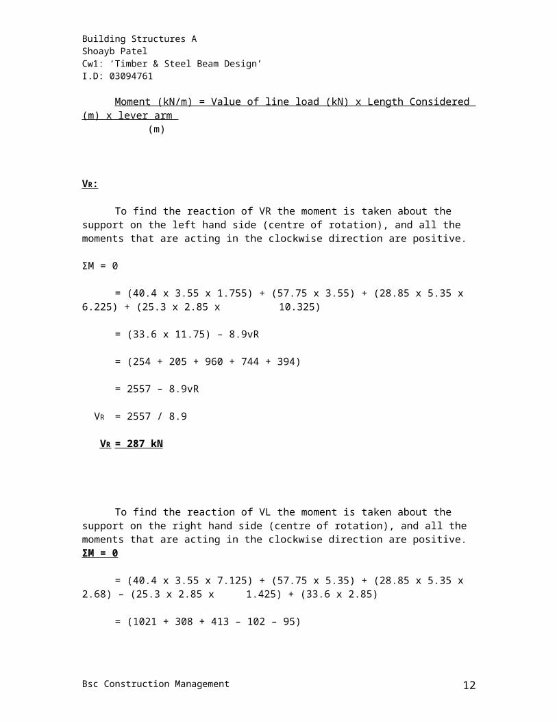
Moment (kN/m) = Value of line load (kN) x Length Considered (m) x lever arm (m)
V R :
To find the reaction of VR the moment is taken about the support on the left hand side (centre of rotation), and all the moments that are acting in the clockwise direction are positive.
ΣM = 0
= (40.4 x 3.55 x 1.755) + (57.75 x 3.55) + (28.85 x 5.35 x 6.225) + (25.3 x 2.85 x 10.325)
= (33.6 x 11.75) – 8.9vR
= (254 + 205 + 960 + 744 + 394)
= 2557 – 8.9vR
VR = 2557 / 8.9
V R = 287 kN
To find the reaction of VL the moment is taken about the support on the right hand side (centre of rotation), and all the moments that are acting in the clockwise direction are positive.ΣM = 0
Bsc Construction Management 9
Building Structures A Shoayb PatelCw1: ‘Timber & Steel Beam Design’ I.D: 03094761
= (40.4 x 3.55 x 7.125) + (57.75 x 5.35) + (28.85 x 5.35 x 2.68) – (25.3 x 2.85 x 1.425) + (33.6 x 2.85)
= (1021 + 308 + 413 – 102 – 95)
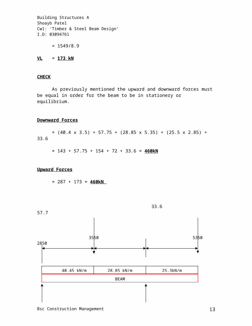
= 1549/8.9
VL = 173 kN
CHECK
As previously mentioned the upward and downward forces must be equal in order for the beam to be in stationery or equilibrium.
Downward Forces
= (40.4 x 3.5) + 57.75 + (28.85 x 5.35) + (25.5 x 2.85) + 33.6
= 143 + 57.75 + 154 + 72 + 33.6 = 460kN
Upward Forces
= 287 + 173 = 460kN
33.6 57.7
3550 5350 2850
173 kN 287kN
(Figure 3: Upwards & Downward Forces)BENDING MOMENTS
Bsc Construction Management 10
40.45 kN/m 28.85 kN/m 25.3kN/m
BEAM
Building Structures A Shoayb PatelCw1: ‘Timber & Steel Beam Design’ I.D: 03094761
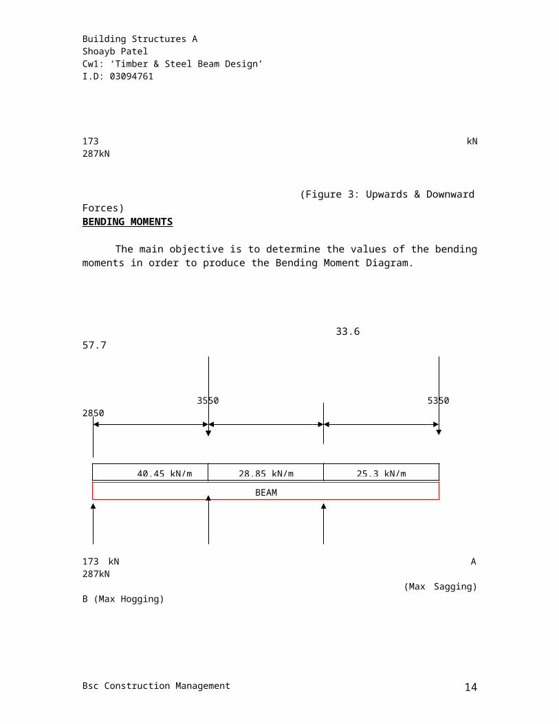
The main objective is to determine the values of the bending moments in order to produce the Bending Moment Diagram.
33.6 57.7
3550 5350 2850
173 kN A 287kN (Max Sagging) B (Max Hogging)
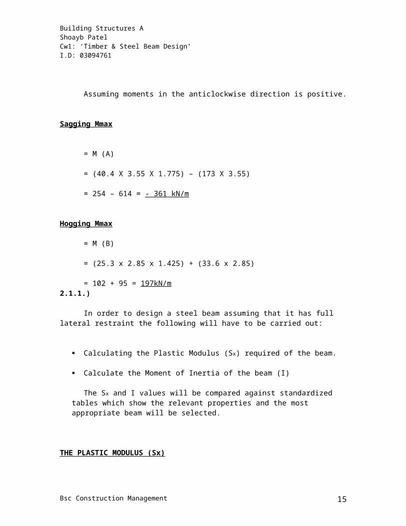
Assuming moments in the anticlockwise direction is positive.
Sagging Mmax
= M (A)
= (40.4 X 3.55 X 1.775) – (173 X 3.55)
= 254 – 614 = - 361 kN/m
Hogging Mmax
= M (B)
= (25.3 x 2.85 x 1.425) + (33.6 x 2.85)
= 102 + 95 = 197kN/m2.1.1.)
Bsc Construction Management 11
40.45 kN/m 28.85 kN/m 25.3 kN/m
BEAM
Building Structures A Shoayb PatelCw1: ‘Timber & Steel Beam Design’ I.D: 03094761
In order to design a steel beam assuming that it has full lateral restraint the following will have to be carried out:
Calculating the Plastic Modulus (Sx) required of the beam.
Calculate the Moment of Inertia of the beam (I)
The Sx and I values will be compared against standardized tables which show the relevant properties and the most appropriate beam will be selected.
THE PLASTIC MODULUS (Sx)
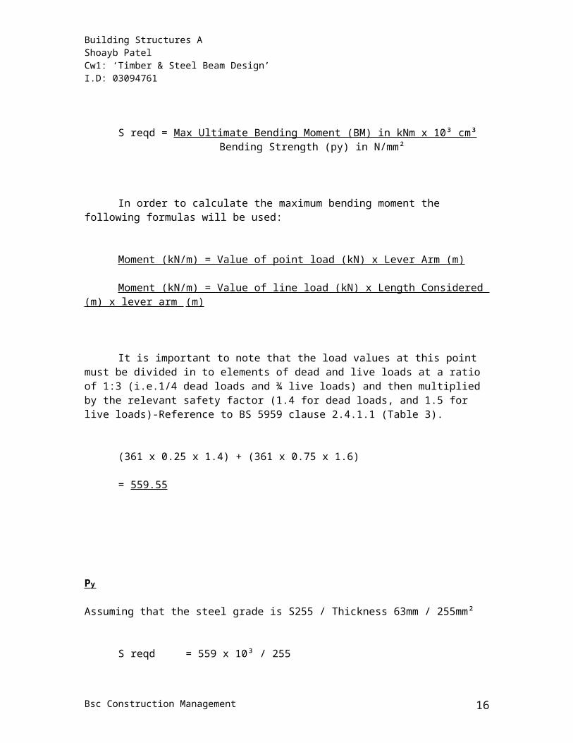
S reqd = Max Ultimate Bending Moment (BM) in kNm x 10³ cm³Bending Strength (py) in N/mm²
In order to calculate the maximum bending moment the following formulas will be used:
Moment (kN/m) = Value of point load (kN) x Lever Arm (m)
Moment (kN/m) = Value of line load (kN) x Length Considered (m) x lever arm (m)
It is important to note that the load values at this point must be divided in to elements of dead and live loads at a ratio of 1:3 (i.e.1/4 dead loads and ¾ live loads) and then multiplied by the relevant safety factor (1.4 for dead loads, and 1.5 for live loads)-Reference to BS 5959 clause 2.4.1.1 (Table 3).
(361 x 0.25 x 1.4) + (361 x 0.75 x 1.6)
= 559.55
P y
Bsc Construction Management 12
Building Structures A Shoayb PatelCw1: ‘Timber & Steel Beam Design’ I.D: 03094761
Assuming that the steel grade is S255 / Thickness 63mm / 255mm²
S reqd = 559 x 10³ / 255
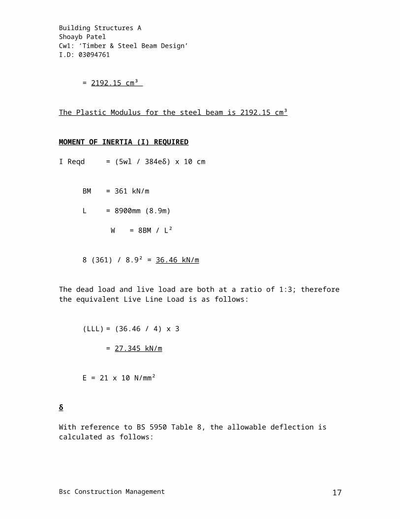
= 2192.15 cm³
The Plastic Modulus for the steel beam is 2192.15 cm³
MOMENT OF INERTIA (I) REQUIRED
I Reqd = (5wl / 384eδ) x 10 cm
BM = 361 kN/m
L = 8900mm (8.9m)
W = 8BM / L²
8 (361) / 8.9² = 36.46 kN/m
The dead load and live load are both at a ratio of 1:3; therefore the equivalent Live Line Load is as follows:
(LLL) = (36.46 / 4) x 3
= 27.345 kN/m
E = 21 x 10 N/mm²
δ
With reference to BS 5950 Table 8, the allowable deflection is calculated as follows:
δ = Span / 360
= 8900 / 360
= 24.7 mm
I Reqd = (5wl / 384eδ) x 10 cm
Bsc Construction Management 13
Building Structures A Shoayb PatelCw1: ‘Timber & Steel Beam Design’ I.D: 03094761
= [(5 x 27.34 x 8900) / (384 x 21 x 104 x 24.7)] x 10
= 43060.6 cm
The section selected for the beam must have a Plastic Modulus of 2192.15 cm³ and a Moment of Inertia value of 43060.6 cm. After looking at the selected tables the possible sections are suitable are as follows:
457 x 191 UB98 S = 2230, I= 45700 356 x 358 UC53 S = 29600, I =48500
It is important to bear in mind that the most suitable selection will depend on its use. This will depend on the governing criterion. The section 457 x 191 UB98 would be most suitable if the weight was the governing criterion. If the depth was the most important issue then the section 356 x 358 UC53 would be more appropriate.
2.1.2.)
Bsc Construction Management 14
Building Structures A Shoayb PatelCw1: ‘Timber & Steel Beam Design’ I.D: 03094761
In order to design a steel beam assuming that it does not have full lateral restraint the following will have to be carried out:
Calculating the maximum buckling resistance moment (Mb)
Calculate the Moment of Inertia of the beam (I)
The Mb and I values will be compared against the tables and select which Mb exceeds the value calculated and spans the required distance.
Maximum Buckling Resistance Movement
The maximum bending moment will have to be calculated, and when selecting a section the following rule will have to be used:
Mb for the appropriate value of LE > max BM from load condition
Max design BM = 559.55 kN/mDimension between supports (LE) = 8.9 rounded to 9m
The section selected for the beam must have a Plastic Modulus of 2192.15 cm³ and a Moment of Inertia value of 43060.6 cm. Also an LE of 9m and an exceeding 559.55 kN/m. After comparing the values to those in the table it is evident that the following sections are suitable:
686 × 254 UB 170 = Mb = 564 I = 170000 356 × 368 UC 153 = Mb = 590 I = 48500
As previously mentioned the most suitable section will again depend on its use. In this case the Universal Column may prove to be a better choice as it is lighter and is likely to meet the governing criterion.
2.2)
Bsc Construction Management 15
Building Structures A Shoayb PatelCw1: ‘Timber & Steel Beam Design’ I.D: 03094761
To comment on the results between 2.1.1 and 2.1.2 it is evident that the beam that does not have full lateral restraint is larger than the one that does have full lateral restraint. This is when comparing the size or the weight of the beam. Universal beams are thinner in comparison to universal columns. They have a thin cross section. As universal columns are thicker they provide more lateral restraint. This is due to the fact that there is more weight present.
When designing beams it is important to consider the concept of ‘lateral-torsional buckling’. It is present in all beams and is caused from stress. When the weight or size of the beam is increased, the beam will provide greater resistance to stiffness and is slender. The beam will put up a greater resistance to the imposed stress.
Bsc Construction Management 16
Building Structures A Shoayb PatelCw1: ‘Timber & Steel Beam Design’ I.D: 03094761
BIBLIOGRAPHY
In order to conduct this assignment I used the following resources;
Books
Ozelton E.C & Baird J.A‘Timber Designers Manual’ (3rd edition), Blackwell publishing, 2002
Lecture Notes
Armitage, D Building Structures A: ‘Steel Beam design to BS 5950’, 2005
Armitage, DBuilding Structures A: ‘Principles of Shear Force, Bending Moment and Deflection’, 2005
Armitage, DBuilding Structures A: ‘Timber Beam Design to BS 5268-2’, 2002
Journals
British standards (2002) British Standards 5268
British standards (2000)
British Standards 5950
The Steel Construction Institute (1992)‘Lateral Stability of steel Beams and Columns’ – Common cases restraint
Bsc Construction Management 17