Embed Size (px)
Citation preview
ASCE CCC – Task Group on Steel-FRP
ASCE COMMITTEE ON COMPOSITE CONSTRUCTIONTASK GROUP ON STEEL-FRP COMPOSITE CONSTRUCTION
Task Group MembersKent A. Harries (chair) University of PittsburghAmit Varma Purdue UniversitySherif El-Tawil University of MichiganJudy Liu Purdue UniversityYan Xiao University of Southern CaliforniaStuart Moy University of Southampton, UKDennis Mertz University of DelawareXiao-Ling Zhao Monash University, Australia (IIFC Liason)Len Hollaway University of Surrey
Objective of Task Group:1. Synthesize existing information on the use of composite FRP/steel structural systems.2. Establish the state-of-the-art and state-of-practice and summarize existing projects in this
nascent field.
Deliverables of Task Group:1. Internal report to committee at 2006 meeting in St Louis.2. Establish sufficient material and interest for session(s) at 2007 Structures Congress in
Long Beach.3. Produce synthesis document aimed at ASCE Journal of Composites for Construction as
the established material warrants.4. Participate in appropriate IIFC Conference
Scope of Task GroupArguably, the most mature application of FRP/Steel composite construction is the use of GFRP bridge decks acting in a composite manner with steel girders. A great number of demonstration projects have been executed primarily through the FHWA IBRC project. These have been largely summarized by Hooks and O’Connor1 (2004). There are a number of ongoing and published studies addressing such systems. Harries is currently serving as editor for a special issue of the ASCE Journal of Bridge Engineering focusing on FRPs in bridge infrastructure. This issue will be largely populated by papers discussing FRP bridge decks. It is for this reason and the fact that this is largely a mature application that it is proposed that the Task Group NOT address issues of FRP bridge decks on steel girders.
Resolution - Scope of Task Group The task group will address FRP bridge deck systems by citation of key documents and reviews. This will be included in the scope but will not be a focus since excellent reviews have already been completed.
1 Hooks, J., and O’Connor, J., 2004. A Summary of Six Years Experience Using GFRP Composites for Bridge Decks, Proceedings of the 21st International Bridge Conference, June 12-14, 2004, Pittsburgh, PA.
version 3.0 – May 2006 – STRUCTURES 2006 – St Louis meeting page 1 of 30
ASCE CCC – Task Group on Steel-FRP
The Task Group should focus on innovative, emerging and under-reported applications of the use of steel-FRP composite systems. The following topics have been identified in this regard:
1. Increasing flexural strength of steel beams by bonding FRP sheets in the tension zone. 2. Inhibiting local and global buckling of steel members using FRP.3. Increasing fatigue life or repairing fatigue cracks using FRP. 4. Using FRP tendons to prestress steel girders. 5. Increasing torsional strength of steel girders using FRP. 6. Improving behavior of conventional steel and concrete composite members by using FRP
Task Group Communication The task group will communicate by email. All editing and comments should be executed using the MSWord “track changes” tool and forwarded to Kent. Please ensure that your “track changes” settings include your user name and that your user name will make sense to those reading your comments (mine is “harries”). Kent will compile changes and distribute updated versions as “clean copies”.
version 3.0 – May 2006 – STRUCTURES 2006 – St Louis meeting page 2 of 30
ASCE CCC – Task Group on Steel-FRP
STEEL-FRP COMPOSITE STRUCTURAL SYSTEMS
ASCE Committee on Composite ConstructionTask Group on Steel-FRP Composite Construction
Sherif El Tawil* University of MichiganKent A. Harries (chair)* University of PittsburghLen Hollaway University of SurreyJudy Liu* Purdue UniversityDennis Mertz University of DelawareStuart Moy University of Southampton, UKAmit Varma Purdue UniversityYan Xiao University of Southern CaliforniaXiao-Ling Zhao (IIFC Liason) Monash University, Australia
1. Introduction1.1 Steel-FRP and Metal-FRP Composite Systems in Other Arenas
2. Fiber Reinforced Polymer (FRP) Composite Materials3. GFRP Bridge Deck Systems Acting Compositely with Steel Girders
3.1 Fiber Reinforced Polymer Bridge Decks3.2 Composite Behavior of GFRP Bridge Decks on Steel Girders
4. Retrofit Systems for Structural Strengthening4.1 Structural Retrofit with FRP4.2 Retrofit of Steel Members with FRP4.3 Strengthening of Flexural Elements4.4 Strengthening of Tensile Elements4.5 Retrofit of Steel Connections
5. Repair of Fatigue Damage and Enhancing Fatigue Life using FRP Materials6. Enhancing Stability of Steel Elements7. Challenges to the Use of FRP Bonded to Steel
7.1 Substrate Preparation 7.2 Behavior of FRP-to-Steel Bond7.3 Environmental Exposure, Creep and Fatigue Behavior7.4 Galvanic Corrosion
8. Future Directions9. References
version 3.0 – May 2006 – STRUCTURES 2006 – St Louis meeting page 3 of 30
ASCE CCC – Task Group on Steel-FRP
1. INTRODUCTION
The use of fiber reinforced polymer (FRP) composite materials has become relatively common in infrastructure applications. Most extant applications involve concrete-FRP composite members. Nonetheless a relatively small and innovative body of work is developing focusing on steel-FRP composite structural systems. With the exception of FRP bridge decks, steel-FRP composite systems are exclusively aimed at retrofit methods for the underlying steel. Whether strengthening, repairing fractures, relieving stress to enhance fatigue performance or enhancing local or member stability, steel-FRP systems leverage the unique material properties of each material in establishing a composite member or structure.
The objective of this report is to synthesize existing information on the use of composite FRP/steel structural systems and to establish the state-of-the-art and state-of-practice in this nascent field. Finally, the authors present their position in terms of what future directions work in steel-FRP composite structural systems may take that appear most promising.
1.1 Steel-FRP and Metal-FRP Composite Systems in Other ArenasBeyond civil infrastructure applications there are few applications of steel (or ferrous)/FRP composite structural systems. Other metal/FRP systems are relatively common in other industries, however. Most are familiar with the use of FRP materials in the automotive and aerospace industries. Typically applications in this case are not “composite” per se but involve simply mating FRP or plastic components with metallic components. True metallic/FRP composites, called fiber metal laminates (FML), are common in modern aerospace applications (Vlot and Gunnink 2001). FML materials are composed of thin sheets of (most commonly) aluminum alternating with traditional FRP materials. The first FML was an aluminum/aramid laminate known as ARALL. The most common FML today is an aluminum/glass laminate known as GLARE. FML materials offer greater damage tolerance and corrosion resistance with a lower specific weight and are thus finding substantial use in high performance applications.
Repair of metallic aerospace and marine structures using FRP materials also has an established industry presence, although in most cases, such repairs are superficial (skin or envelope) rather than structural (airframe or hull). The aerospace and marine industries provide a great deal of background for the adoption of FRP/steel composites in civil applications. Guidance on substrate preparation, FRP geometry and terminations and joining are all available. Nonetheless, it must be recalled that these industries (and more so, biomedical applications) are largely performance driven with cost being of secondary consideration. In civil applications, clearly cost is the driving factor. Thus paradigms of the design of FRP/metallic composite systems and their use will shift as civil applications are explored and considered.
version 3.0 – May 2006 – STRUCTURES 2006 – St Louis meeting page 4 of 30
ASCE CCC – Task Group on Steel-FRP
2. FIBER REINFORCED POLYMER (FRP) COMPOSITE MATERIALS
Fiber reinforced polymer (FRP) composite materials combine high-modulus, high strength fibers in a low-modulus polymeric matrix which ensures load transfer between the fibers. The strength and stiffness of an FRP composite is largely determined by the fiber type and fiber architecture. FRP materials that are suited to civil infrastructure and structural engineering applications typically use high strength, high modulus fibers in relatively high fiber-volume fractions. Orientation of the fibers is controlled so that the resulting FRP is anisotropic. FRPs enable high mechanical stress to be carried safely and allow the material to be tailored to suit the local stress patterns in the component to be retrofit. The in-service performance of a composite is influenced both by the fiber and matrix material.
Carbon (CFRP) and glass (GFRP) FRP materials are ubiquitous in the field of structural retrofit. CFRP may be high strength (hsCFRP), high modulus (hmCFRP) and, most recently, ultra-high modulus (uhmCFRP). Generally an increase in CFRP stiffness is accompanied by a reduction in strength and rupture strain of the fiber. GFRP (most typically based on E-glass fibers) have a much lower modulus than CFRP and are somewhat less expensive on a unit stiffness basis. To be effective in strengthening applications, the modulus of the FRP selected for a particular application should be compatible with the substrate material. For this reason, CFRP materials have often been used with a steel substrate.
A polymeric matrix binds and protects the fibers of an FRP, transferring force into, and between, fibers through interfacial shear. The matrix also provides stability and environmental protection to the slender, delicate fibers. Epoxy resin systems are most commonly used as the matrix in hand lay-up applications and as the adhesive in plate bonding techniques. Polyester resin systems are often used as the matrix material in preformed composite materials such as those used for plate bonding applications.
In terms of ease of handling, installation and quality control, preformed CFRP plates or strips are rapidly becoming the preferred products for structural retrofit. The exception is that wet lay-up fabrics remain appropriate for applications involving retrofit forming around corners (column wrapping, shear strengthening of beams using “U-wraps”). In either case the resulting system has
version 3.0 – May 2006 – STRUCTURES 2006 – St Louis meeting page 5 of 30
1.2 International Research The International Institute for FRP in Construction (IIFC) has initiated a task group on FRP-Strengthened Metallic Structures. The membership of this task group, chaired by Xiao-Ling Zhao of Monash University, has assembled a bibliography of 118 international journal papers, conference articles and theses/dissertations related to the topic. Additionally, this task group is convening a special Workshop in Sydney in December 2007.
We may provide a link to this bibliography or, with Dr. Zhao’s blessing include it as an Appendix to the present document.Question to TG: any thoughts?Clarification: there is no planned IIFC report at this time. There will be a special conference however – December 2007 in Australia.
ASCE CCC – Task Group on Steel-FRP
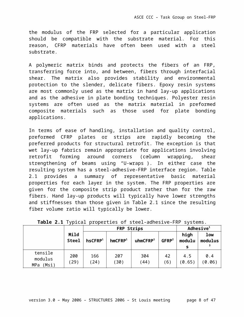
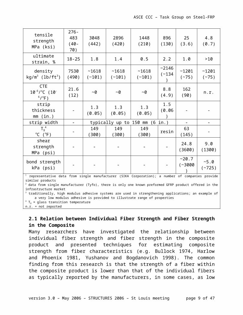
a steel-adhesive-FRP interface region. Table 2.1 provides a summary of representative basic material properties for each layer in the system. The FRP properties are given for the composite strip product rather than for the raw fibers. Hand lay-up products will typically have lower strengths and stiffnesses than those given in Table 2.1 since the resulting fiber volume ratio will typically be lower.
Table 2.1 Typical properties of steel-adhesive-FRP systems.
Mild Steel
FRP Strips Adhesive1
hsCFRP1 hmCFRP1 uhmCFRP1 GFRP2 high modulus
low modulus3
tensile modulusMPa (Msi)
200 (29)
166(24)
207(30)
304(44)
42(6)
4.5(0.65)
0.4(0.06)
tensile strengthMPa (ksi)
276-483
(40-70)
3048(442)
2896(420)
1448(210)
896(130)
25(3.6)
4.8(0.7)
ultimate strain, % 18-25 1.8 1.4 0.5 2.2 1.0 >10density
kg/m3 (lb/ft3)7530(490)
~1618(~101)
~1618(~101)
~1618(~101)
~2146(~134)
~1201(~75)
~1201(~75)
CTE10-6/oC (10-6/oF)
21.6(12) ~0 ~0 ~0 8.8
(4.9)162(90) n.r.
strip thicknessmm (in.) - 1.3
(0.05)1.3
(0.05)1.3
(0.05)1.5
(0.06) - -
strip width - typically up to 150 mm (6 in.) - -Tg
4
oC (oF) - 149 (300) 149 (300) 149 (300) resin 63 (145) -
shear strengthMPa (psi) - - - - - 24.8
(3600)9.0
(1300)bond strength
kPa (psi) - - - - - ~20.7(~3000)
~5.0(~725)
1 representative data from single manufacturer (SIKA Corporation); a number of companies provide similar products2 data from single manufacturer (Tyfo), there is only one known preformed GFRP product offered in the infrastructure market3 traditionally, high modulus adhesive systems are used in strengthening applications; an example of a very low modulus adhesive is provided to
illustrate range of properties4 Tg = glass transition temperaturen.r. = not reported
2.1 Relation between Individual Fiber Strength and Fiber Strength in the CompositeMany researchers have investigated the relationship between individual fiber strength and fiber strength in the composite product and presented techniques for estimating composite strength from fiber characteristics (e.g. Bullock 1974, Harlow and Phoenix 1981, Yushanov and Bogdanovich 1998). The common finding from this research is that the strength of a fiber within the composite product is lower than that of the individual fibers as typically reported by the manufacturers, in some cases, as low as 40-50%. While some engineers investigating uses of FRP materials for strengthening applications have performed coupon tests to estimate the tensile strength of FRP reinforcement, there are some instances in the literature where composite fiber strength was assumed equal to the manufacturer reported fiber strength, which is unconservative. Nevertheless, an unconservative estimate of laminate strength is inconsequential if the modes of failure under study do not involve composite rupture, but rather substrate and/or bond related failures. In an attempt to develop a design oriented technique for specifying composite product strength as a function of manufacturer reported fiber strength, Okeil et al. (2001) used the
version 3.0 – May 2006 – STRUCTURES 2006 – St Louis meeting page 6 of 30
ASCE CCC – Task Group on Steel-FRP
Weibull theory to establish a relationship between the fiber tensile strength and the tensile strength of CFRP laminates. They showed that the proposed model reasonably replicates test results for reinforced concrete beams strengthened with CFRP laminates. They also pointed out that FRP products have a size effect associated with them and so FRP strength derived from small coupon tests could be misleading. In practice, FRP strips are becoming the dominant product. In this case, manufacturers are generally reporting in situ strengths and stiffnesses based on appropriate coupon testing. Examples of such values are given in Table 2.1.
3. GFRP BRIDGE DECK SYSTEMS ACTING COMPOSITELY WITH STEEL GIRDERS
Arguably, the most mature application of FRP/steel composite construction is the use of glass FRP (GFRP) bridge decks acting in a composite manner with steel girders. A great number of demonstration projects have been executed primarily through the FHWA IBRC project. These have been largely summarized by Hooks and O’Connor (2004).
GFRP decks are attractive because of their minimal installation time, high strength-to-weight ratios, and excellent tolerance to frost and de-icing salts. Their light weight, and thus reduced dead load, is particularly attractive for rehabilitating posted structures since the replacement of heavy conventional concrete decking with lighter weight GFRP decking may translate to additional live load carrying capacity of the bridge system.
Curiously however, despite this latter advantage, most of the bridges currently employing GFRP decks in their designs are new superstructure (girders and deck) as opposed to rehabilitation applications. Using GFRP deck panels in a new design may not be as practical as using them for rehabilitation projects. The deck panels themselves are initially more expensive than their equivalent concrete slab counterparts and there is not likely to be a great savings to be had from the reduced dead load. The installation time, however, can be as little as one working day for a relatively short span bridge. This is a significant time savings over placing a concrete deck and may warrant the selection of a GFRP deck in some circumstances.
The eventual use of GFRP decks for new bridge construction is unclear. Light-weight GFRP decks are attractive for certain applications such as moving spans (bascules, etc.) and bridges located in remote areas where placing a concrete deck may be impractical (Moses et al. 2006). Currently, there are no AASHTO guidelines for the application of GFRP decks and designers appear to treat these decks as “equivalent to concrete”. Based on the observations of studies reported above, this is not the case.
For rehabilitation, however, the reduced dead load of a GFRP deck may represent a significant advantage possibly allowing load posting to be removed or an increase in the bridge rating to be made. For example, a typical commercially available deck system weighs approximately one fifth of what a comparable concrete deck would weigh. Similarly, for historic bridge structures, the reduced deck load may permit increased load rating without altering the original state of the bridge. Nonetheless, there are implications to the use of GFRP decks associated with reduced apparent effective width and increased distribution factors as discussed in the following sections. The rapid installation of a GFRP deck also reduces bridge closure time for a rehabilitation project.
version 3.0 – May 2006 – STRUCTURES 2006 – St Louis meeting page 7 of 30
ASCE CCC – Task Group on Steel-FRP
3.1 Fiber Reinforced Polymer Bridge DecksGFRP bridge decks capable of replacing typical 200 to 250 mm (8 to 10 in.) thick reinforced concrete decks (weighing 4.8 to 6.0 kPa (100 to 125 psf)) typically weigh about 0.96 kPa (20 psf) without a wearing surface, representing a significant savings in the dead load of the superstructure.
Although there have been a variety of proprietary GFRP bridge deck systems that have been proposed and demonstrated, this work focuses on those systems designed to span transversely between longitudinal bridge girders, typically acting in a composite manner with the girders. Such decks carry traffic loads in a manner similar to a “one way” concrete deck and typically take one of three fundamental forms:
1. A series of closed-shape pultruded GFRP tubes that are sandwiched between top and bottom face plates. The tubes and face plate components are assembled using a structural adhesive. (examples include Crocker et al. 2002 and Zhou et al. 2002). A variation on this form using an arrangement of perpendicular tubes and no face plates is presented by Chandrashekhara and Nanni (2000).
2. A series of interlocking pultruded shapes which include both face plates and web elements (examples include Motley et al. 2002 and GangaRao et al. 1999). Such systems are generally more versatile and have better final product quality control than adhesively assembled tubes.
3. Sandwich panel structures consisting of face plates and a core section. The core configuration may vary but examples include fiber reinforced foam (Stoll and Banerjee 2002) and vertically (through the deck thickness) oriented pultruded fiber shapes or plates typically referred to as “honeycomb panels” (Gillespie et al. 2000; Kalny et al. 2002).
According to the American Composites Manufacturers Association (ACMA), there are (as of July 2005) 83 existing road bridges in the United States having GFRP decks. Of these, approximately 38 are GFRP deck-on-steel girder structures having girder spacing over which the GFRP deck spans ranging from 800 mm (31.5 in.) to 2840 mm (112 in.). The majority of these applications are represented by the second deck type described above.
3.2 Composite Behavior of GFRP Bridge Decks on Steel GirdersA number of in situ tests of GFRP decks on steel girders have indicated that the decks can be made to behave in a composite manner with the girders at service load levels. The limited data available from most in situ tests have led researchers to report the composite action as an apparent effective width of GFRP deck acting in full composite action with the girder. The degree of composite action available, however, is greatly reduced due to the relatively low axial stiffness (EA) of the GFRP.
Keller and Gurtler (2005) demonstrated that degree of composite behavior that may be achieved is affected by the in-plane longitudinal shear stiffness of the GFRP deck. In a study of GFRP deck adhesively connected to steel girders while there was no strain discontinuity reported at the steel girder-FRP deck interface, there was significant through-deck shear lag between the top and
version 3.0 – May 2006 – STRUCTURES 2006 – St Louis meeting page 8 of 30
ASCE CCC – Task Group on Steel-FRP
bottom face plates of the GFRP deck resulting top plate strains of only approximately 55% of those observed in the bottom face plate.
Keller et al. (2004) report results using two different GFRP deck systems designed to carry comparable loading. Nonetheless, the deck cell geometry differed such that the in-plane shear stiffness of the decks differed by a factor of eight. The deck having lower in-plane shear stiffness exhibited a composite stiffness at service load level of only 74% of that of the stiffer deck. Additionally, the ultimate failure mode of the two deck types differed: the deck having lower in-plane shear stiffness failed in the bottom face plate while the stiffer deck exhibited a failure that engaged the entire deck depth. The same study also clearly demonstrated a transverse shear lag across the deck at the ultimate limit state, although a relatively uniform transverse stress distribution at service load levels. The presence of a transverse shear lag reduces the efficiency of the GFRP deck acting compositely with the girder. The transverse results suggest a notable different behavior, in this case, between service and ultimate load levels. These observations point to the relative importance of the through-deck and transverse shear lag phenomenon when evaluating compositeness in FRP-steel bridge girder systems.
Keller’s research involved GFRP decks adhesively connected to steel girders. This is a unique application which is believed to result in a more uniform (and therefore efficient) shear transfer between the girder and deck than the more conventional use of shear studs. Shear stud connections of steel to GFRP decks typically involve the use of multiple-stud groups embedded in discrete cells of the GFRP deck which are then locally grouted. In the most common application, the resulting grouted pocket is approximately 180 mm (7 in.) long and 450 mm (18 in.) wide, relative to, and centered on, the underlying girder flange. The spacing between grout pockets is most typically 610 mm (24 in.).
3.2.1 Stud Capacity Push-Off TestsStandard push-off style tests are used to determine the shear capacity of embedded studs connecting steel girders and GFRP decks. Both Moon et al. (2002) and Turner et al. (2003) report the average capacity of shear studs embedded in a GFRP deck grout pocket to be approximately 70-80% of the capacity of a comparable shear connection in a continuous concrete deck. Similar tests conducted by Yulismana (2005) showed that the shear studs were only able to achieve 52-58 % of their nominal capacity (defined by the shear capacity of the stud). Only tests conducted by Drexler (2005) report studs actually achieving their nominal capacity, although these tests utilized two sets of shear stud connections on each side of the test specimen. Such a non-traditional test arrangement is believed to result in greater observed capacities.
The observed inability to achieve the stud shear capacity was due to failure modes associated with crushing (Moon et al. 2002) or delamination (Turner et al. 2003 and Yulismana 2005) of the GFRP decks. The failure reported by Turner et al. involved the web of the GFRP deck separating from the face plate.
3.2.2 Moment Distribution FactorsMoment distribution factors (DF) are design tools used to determine the maximum expected moment each supporting girder must be able to resist given the strength contributions of adjacent
version 3.0 – May 2006 – STRUCTURES 2006 – St Louis meeting page 9 of 30
ASCE CCC – Task Group on Steel-FRP
superstructure elements. Alternatively, they may be seen as factors describing the manner in which the design loads will be distributed to the supporting girders making up the superstructure. These factors are given as a fraction of the design load. An accurate assessment of moment distribution factors is critical for bridge design. The use of GFRP decks requires an evaluation of distribution factors for these decks so that girder design forces are appropriately evaluated. For bridge deck replacement applications, the behavior of the replacement deck should approximate that of the original deck with regard to distribution. If, for instance, the distribution is more critical (less transverse distribution of wheel loads) for the replacement GFRP deck, some girders will see proportionately greater stress due to a given live load; as compared with the previous condition with the replaced deck system. It is also important to note that the reduced dead load of the GFRP deck does have the effect of reducing overall girder stresses but may adversely affect the live load-induced stress range which may be critical for fatigue considerations. Thus, distribution factors for GFRP replacement decks that differ significantly from those of the original concrete decks may, in fact, aggravate fatigue-sensitive details (Harries and Moses 2006).
A study of moment distributions factors determined from in situ service load tests of multiple bridge structures indicates that the “lever rule” (AASHTO 2004) results in adequately conservative distribution factors for use in design (Moses et al. 2006). Refining the calculation of distribution factors beyond this approximation will require a significantly broader database to be established.
4. RETROFIT SYSTEMS FOR STRUCTURAL STRENGTHENING
4.1 Structural Retrofit with FRPA great deal of work has been conducted on the use of externally bonded FRP systems for the structural strengthening of building systems and components. The overwhelming majority of this work has focused on the retrofit of reinforced concrete structures. In virtually every existing application, FRP materials are being used “in place of steel reinforcement”. Indeed, early FRP external bonding applications were developed as an alternative to very heavy and awkward steel plate bonding techniques (Meier et al. 1993; McKenna and Erki 1994). In some applications, the analogy to steel is appropriate; however this paradigm is restrictive and does not always result in an efficient use of the relatively unique properties of FRP materials: their high stiffness, strength and linear behavior.
There is a variety of design guidance available for the use of externally bonded FRP materials for the retrofit and rehabilitation of concrete structures (ACI 2002; fib 2001; ISIS 2001; JSCE 2001, among others). Current research in the area has a strong emphasis on issues of the durability of the bonded FRP and the nature and behavior of the bonding mechanism itself. The bond of FRP to concrete can only be as strong as the substrate concrete and may fail through a variety of mechanisms, some associated with classical debonding mechanisms (an overview of debonding mechanisms and a summary of a number of debonding models are provided by Teng et al. (2002)) and others associated with the behavior and condition of the concrete substrate. Provided adequate quality control is executed, the behavior of externally bonded FRP will be largely governed by the substrate concrete. This will not be the case for a stronger steel substrate, allowing more conventional bond mechanics to be used to describe debonding behavior.
version 3.0 – May 2006 – STRUCTURES 2006 – St Louis meeting page 10 of 30
ASCE CCC – Task Group on Steel-FRP
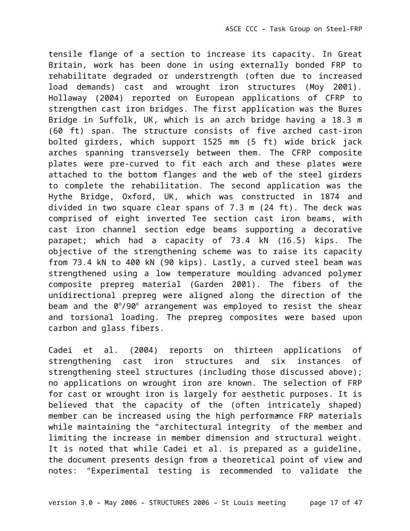
4.2 Retrofit of Steel Members with FRPThere is comparatively little work done investigating the use of bonded FRP materials for the retrofit of steel members. Most available research and guidance focuses on the use FRP for flexural retrofit: generally, applying FRP materials to the tensile flange of a section to increase its capacity. In Great Britain, work has been done in using externally bonded FRP to rehabilitate degraded or understrength (often due to increased load demands) cast and wrought iron structures (Moy 2001). Hollaway (2004) reported on European applications of CFRP to strengthen cast iron bridges. The first application was the Bures Bridge in Suffolk, UK, which is an arch bridge having a 18.3 m (60 ft) span. The structure consists of five arched cast-iron bolted girders, which support 1525 mm (5 ft) wide brick jack arches spanning transversely between them. The CFRP composite plates were pre-curved to fit each arch and these plates were attached to the bottom flanges and the web of the steel girders to complete the rehabilitation. The second application was the Hythe Bridge, Oxford, UK, which was constructed in 1874 and divided in two square clear spans of 7.3 m (24 ft). The deck was comprised of eight inverted Tee section cast iron beams, with cast iron channel section edge beams supporting a decorative parapet; which had a capacity of 73.4 kN (16.5) kips. The objective of the strengthening scheme was to raise its capacity from 73.4 kN to 400 kN (90 kips). Lastly, a curved steel beam was strengthened using a low temperature moulding advanced polymer composite prepreg material (Garden 2001). The fibers of the unidirectional prepreg were aligned along the direction of the beam and the 0o/90o arrangement was employed to resist the shear and torsional loading. The prepreg composites were based upon carbon and glass fibers.
Cadei et al. (2004) reports on thirteen applications of strengthening cast iron structures and six instances of strengthening steel structures (including those discussed above); no applications on wrought iron are known. The selection of FRP for cast or wrought iron is largely for aesthetic purposes. It is believed that the capacity of the (often intricately shaped) member can be increased using the high performance FRP materials while maintaining the “architectural integrity” of the member and limiting the increase in member dimension and structural weight. It is noted that while Cadei et al. is prepared as a guideline, the document presents design from a theoretical point of view and notes: “Experimental testing is recommended to validate the design procedures presented herein. Appropriate test programs should also be undertaken as a part of major strengthening schemes.” A lengthy list of requirements for future research and a sparse list of demonstration applications illustrate that the use of FRP to retrofit steel members is very much in its infancy. Nonetheless, the Cadei et al. document represents the state-of-the-art for FRP strengthening of steel structures.
4.3 Strengthening of Flexural ElementsIn the United States, two NCHRP-IDEA projects (IDEA-011 (Mertz and Gillespie 1996) and IDEA-051 (Mertz et al. 2002)) were performed by the University of Delaware in the late 1990’s. These projects focused on the flexural strengthening of corroded bridge girders and addressed only the use of bonded FRP materials on the tension flange of simple girders. The rationale was that the bottom flange of bridge girders typically see the greatest level of corrosion, largely due to debris accumulation.
version 3.0 – May 2006 – STRUCTURES 2006 – St Louis meeting page 11 of 30
ASCE CCC – Task Group on Steel-FRP
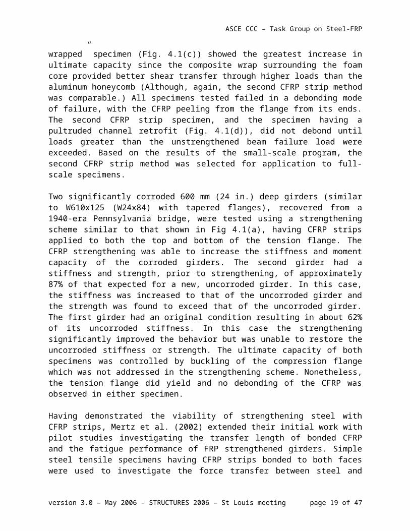
In the earlier study, Mertz and Gillespie (1996) report on six small scale tests of 1525 mm (60 in.) long W200x15 (W8x10) members retrofit with the five different adhesively bonded schemes; shown in Figure 4.1 (the fifth scheme was similar to that shown in Fig 4.1(a) using a different CFRP material.) All specimens demonstrated an increase in flexural stiffness and strength compared to the un-strengthened control specimen. As might be expected, the “sandwich-reinforced” specimen (Fig. 4.1(b)), having the additional FRP material located a distance below the flange showed the greatest improvement in stiffness and elastic strength (although the second CFRP strip retrofit Fig 4.1(a) was comparable for both parameters). The “composite-wrapped” specimen (Fig. 4.1(c)) showed the greatest increase in ultimate capacity since the composite wrap surrounding the foam core provided better shear transfer through higher loads than the aluminum honeycomb (Although, again, the second CFRP strip method was comparable.) All specimens tested failed in a debonding mode of failure, with the CFRP peeling from the flange from its ends. The second CFRP strip specimen, and the specimen having a pultruded channel retrofit (Fig. 4.1(d)), did not debond until loads greater than the unstrengthened beam failure load were exceeded. Based on the results of the small-scale program, the second CFRP strip method was selected for application to full-scale specimens.
Two significantly corroded 600 mm (24 in.) deep girders (similar to W610x125 (W24x84) with tapered flanges), recovered from a 1940-era Pennsylvania bridge, were tested using a strengthening scheme similar to that shown in Fig 4.1(a), having CFRP strips applied to both the top and bottom of the tension flange. The CFRP strengthening was able to increase the stiffness and moment capacity of the corroded girders. The second girder had a stiffness and strength, prior to strengthening, of approximately 87% of that expected for a new, uncorroded girder. In this case, the stiffness was increased to that of the uncorroded girder and the strength was found to exceed that of the uncorroded girder. The first girder had an original condition resulting in about 62% of its uncorroded stiffness. In this case the strengthening significantly improved the behavior but was unable to restore the uncorroded stiffness or strength. The ultimate capacity of both specimens was controlled by buckling of the compression flange which was not addressed in the strengthening scheme. Nonetheless, the tension flange did yield and no debonding of the CFRP was observed in either specimen.
Having demonstrated the viability of strengthening steel with CFRP strips, Mertz et al. (2002) extended their initial work with pilot studies investigating the transfer length of bonded CFRP and the fatigue performance of FRP strengthened girders. Simple steel tensile specimens having
version 3.0 – May 2006 – STRUCTURES 2006 – St Louis meeting page 12 of 30
Figure 4.1 Small-scale specimens tested by Mertz and Gillespie.
ASCE CCC – Task Group on Steel-FRP
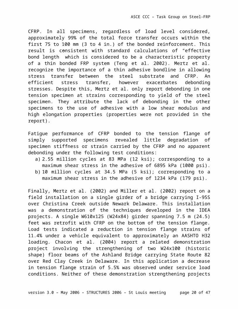
CFRP strips bonded to both faces were used to investigate the force transfer between steel and CFRP. In all specimens, regardless of load level considered, approximately 99% of the total force transfer occurs within the first 75 to 100 mm (3 to 4 in.) of the bonded reinforcement. This result is consistent with standard calculations of “effective bond length” which is considered to be a characteristic property of a thin bonded FRP system (Teng et al. 2002). Mertz et al. recognize the importance of a thin adhesive bondline in allowing stress transfer between the steel substrate and CFRP. An efficient stress transfer, however exacerbates debonding stresses. Despite this, Mertz et al. only report debonding in one tension specimen at strains corresponding to yield of the steel specimen. They attribute the lack of debonding in the other specimens to the use of adhesive with a low shear modulus and high elongation properties (properties were not provided in the report).
Fatigue performance of CFRP bonded to the tension flange of simply supported specimens revealed little degradation of specimen stiffness or strain carried by the CFRP and no apparent debonding under the following test conditions:
a) 2.55 million cycles at 83 MPa (12 ksi); corresponding to a maximum shear stress in the adhesive of 6895 kPa (1000 psi).
b) 10 million cycles at 34.5 MPa (5 ksi); corresponding to a maximum shear stress in the adhesive of 1234 kPa (179 psi).
Finally, Mertz et al. (2002) and Miller et al. (2002) report on a field installation on a single girder of a bridge carrying I-95S over Christina Creek outside Newark Delaware. This installation was a demonstration of the techniques developed in the IDEA projects. A single W610x125 (W24x84) girder spanning 7.5 m (24.5) feet was retrofit with CFRP on the bottom of the tension flange. Load tests indicated a reduction in tension flange strains of 11.4% under a vehicle equivalent to approximately an AASHTO H32 loading. Chacon et al. (2004) report a related demonstration project involving the strengthening of two W24x100 (historic shape) floor beams of the Ashland Bridge carrying State Route 82 over Red Clay Creek in Delaware. In this application a decrease in tension flange strain of 5.5% was observed under service load conditions. Neither of these demonstration strengthening projects were strictly necessary – the strengthened girder and floor beams did not require strengthening. Rather, the projects are intended to serve as test beds to investigate the long term performance and durability of CFRP strengthening techniques for steel bridge girders.
Deng et al. (2003) presented analytical work where the stresses in steel beams reinforced with a bonded CFRP plate under mechanical and thermal loads were calculated. Finite element analysis was employed to validate the analytical results. A parametric study was carried out to show how the maximum stresses were influenced by the dimensions the material properties of the adhesive and the adherends.
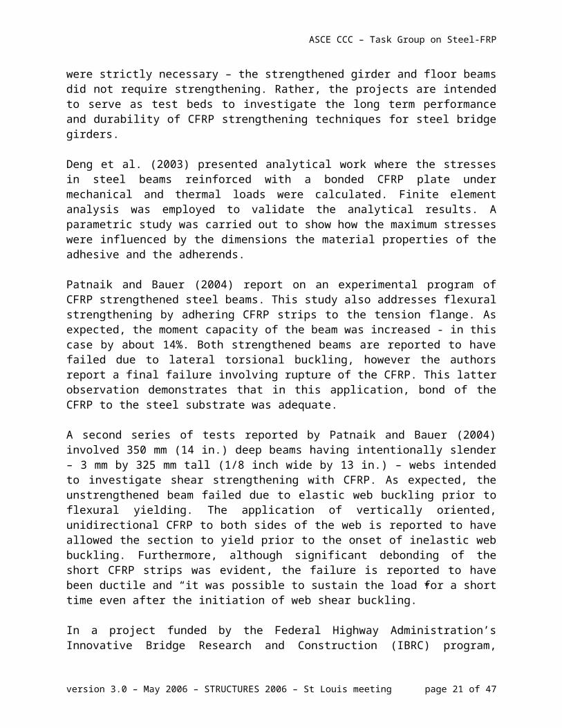
Patnaik and Bauer (2004) report on an experimental program of CFRP strengthened steel beams. This study also addresses flexural strengthening by adhering CFRP strips to the tension flange. As expected, the moment capacity of the beam was increased - in this case by about 14%. Both strengthened beams are reported to have failed due to lateral torsional buckling, however the authors report a final failure involving rupture of the CFRP. This latter observation demonstrates that in this application, bond of the CFRP to the steel substrate was adequate.
version 3.0 – May 2006 – STRUCTURES 2006 – St Louis meeting page 13 of 30

ASCE CCC – Task Group on Steel-FRP
A second series of tests reported by Patnaik and Bauer (2004) involved 350 mm (14 in.) deep beams having intentionally slender – 3 mm by 325 mm tall (1/8 inch wide by 13 in.) – webs intended to investigate shear strengthening with CFRP. As expected, the unstrengthened beam failed due to elastic web buckling prior to flexural yielding. The application of vertically oriented, unidirectional CFRP to both sides of the web is reported to have allowed the section to yield prior to the onset of inelastic web buckling. Furthermore, although significant debonding of the short CFRP strips was evident, the failure is reported to have been ductile and “it was possible to sustain the load for a short time even after the initiation of web shear buckling.”
In a project funded by the Federal Highway Administration’s Innovative Bridge Research and Construction (IBRC) program, Phares et al. (2003) attempted to use CFRP post-tensioning rods to improve the structural response of a steel bridge. A CFRP post-tensioning system was installed in the positive moment region of an existing bridge in an effort to improve its live load carrying capacity. Although the system provided little enhancement to the stiffness of the bridge, approximately 5 to 10 percent of the live load moment at critical sections was reduced by the post-tensioning system. It is not clear from the study whether such an approach provides benefits over the more traditional bonded reinforcement.
Schnerch et al. (2004) investigated resin and adhesive selection for wet lay-up of carbon fiber sheets and bonding of pre-cured laminate plates and their effect on the flexural behavior of a steel monopole. Resin selection for the wet lay-up process was determined through testing of double lap shear coupons using ten different resins. A Super-Light Beam (SLB) with an additional steel plate welded along the length of the compression flange was used to determine the development length of the strengthening technique (Schnerch et al. 2006). It is reported that the addition of the steel plate in the compression region simulates the presence of a concrete slab by decreasing the neutral axis depth such that the strain profile of the cross-section would be similar to that in a bridge girder acting compositely with a concrete deck. The test results showed a 25% increase in the elastic stiffness of the steel monopole resulting from the application of a limited number of CFRP sheets.
Al-Saidy et al. (2004) investigated the effect of CFRP plates on the behavior of composite steel-concrete beams. The investigation focused on the behavior of beams damaged intentionally at their tension flange to simulate corrosion and then repaired with carbon fiber-reinforced polymer plates attached to the tension area. Damage to the beams was induced by removing part of the bottom flange; varying between no damage and a loss of 75% of the bottom flange. All beams were tested to failure to observe their behavior in the elastic, inelastic, and ultimate states. The test results showed that the elastic flexural stiffness of damaged beams can be partially restored (up to 50%); whereas the strength of damaged beams can be fully restored to their original, undamaged state using the particular CFRP plates investigated.
Other similar investigations of the use of CFRP strips attached to the tension flange of I-girders have demonstrated generally improved flexural capacity although little improvement to girder stiffness (Sen et al. 2000; Tavakkolizadeh and Saadatmanesh 2003a). Both studies utilized moderate scale rolled sections (W200x35.9 (W8x24) and W360x101 (W14 x 68), respectively) having composite concrete slabs. Various amounts of CFRP were utilized and proportional
version 3.0 – May 2006 – STRUCTURES 2006 – St Louis meeting page 14 of 30
ASCE CCC – Task Group on Steel-FRP
increases in flexural capacity of the composite girders were observed accordingly. Regardless of the amount of CFRP used, little increase in elastic stiffness is observed. This is attributed to the relatively small contribution of the CFRP to the section modulus and the relative flexibility of the adhesive (Tavakkolizadeh and Saadatmanesh 2003).
Lenwari et al. (2005) reported on the flexural behavior of steel beams that were strengthened with partial-length, adhesive-bonded CFRP plates. Seven steel beams were strengthened with three different CFRP lengths, attached to the bottom flange of the beam and tested under four-point loading. Two different failure modes were observed: plate debonding at their ends in beams with short plates; and plate rupture at midspan in beams with long plates. The authors concluded that the attached CFRP plates significantly increased the strength and extended the elastic range of the beams. An analytical method was also proposed to evaluate the flexural behavior of the strengthened beams.
Photiou et al. (2006) investigated the effectiveness of C/GFRP hybrid prepreg materials having two different moduli in strengthening artificially degraded steel beams of rectangular cross-section under four-point loading. First, two beams were upgraded with U shaped prepreg units, which extended up the vertical sides of the beam to the neutral axis height. Another two beams were strengthened using prepreg strips attached only to their soffit. The hybrid prepreg units were composed of carbon and glass fiber reinforced polymers and all the specimens had the same hybrid lay-up although two different moduli CFRP were used. The authors reported that the failure load for all specimens exceed the plastic collapse load of the undamaged beam and by using the U-shaped configuration for the fibers, composite action was provided between the steel member and fiber layer leading to better performance even at failure levels. Debonding was observed for the specimens which had fiber layers only on the soffit
Lenwari et al. (2006) investigated the debonding strength of partial-length, adhesively bonded CFRP plates used to strengthen steel beams. Static and fatigue tests were conducted with steel beams strengthened with CFRP to investigate possible reasons of debonding under four-point loading. Variables studied were CFRP plate thickness and modulus, adhesive bondline thickness, adhesive modulus, and adhesive spew-fillet angle. The authors concluded that the stress intensity at the end of CFRP plates governs the debonding strength and that this region was critical for the initiation of debonding.
Nozaka et al. (2005) proposed an alternative technique to single and double lap specimen testing for obtaining the effective bond length of CFRP strips. Since most of the civil engineering applications do not have an orientation similar to single or double lap geometry, stress distribution in the adhesive layer was analyzed and a more suitable specimen model and test setup were proposed. The proposed alternative for assessing the effective bond length for the adhesive/CFRP system was demonstrated by comparing results with a prototype repaired bridge with CFRP strip. Weaknesses and strengths of standard single-lap and double-lap specimens were also discussed. They reported that the new test setup which accounts for flexure together with tension would be more accurate for obtaining the effective bond length for polymers in civil engineering applications
version 3.0 – May 2006 – STRUCTURES 2006 – St Louis meeting page 15 of 30
ASCE CCC – Task Group on Steel-FRP
Colombi and Poggi (2005a) discussed the results of an experimental and numerical program to characterize the static behavior of steel beams strengthened with pultruded CFRP strips. H-shaped steel beams with different CFRP reinforcement geometries bonded to the tension flanges using different epoxy adhesives were tested under three point bending. Force transfer mechanisms, strength and stiffness of the beams were the main interest of the study. Results were validated with different analytical and numerical models and with a finite element model developed by the authors. (comment on conclusions of this study required)
4.4 Strengthening of Tensile Elements
Jiao and Zhao (2004) tested 21 butt-welded very high strength (VHS) steel tubes strengthened with CFRP in axial tension. Lap shear strength between CFRP and VHS tubes was obtained as a preliminary study before testing the welded connections. Three types of failure were reported: adhesive failure, fiber tear and mixed failure. The authors concluded that significant strength increase was achieved using the CFRP-epoxy strengthening technique and proposed a theoretical model to estimate the load carrying capacity of butt-welded VHS tubes strengthened with CFRP
An experimental and numerical study was carried out by Colombi and Poggi (2005b) to verify the effectiveness of CFRP pultruded plates to reinforce tensile steel members. Three different sets of specimens were tested under axial tension. In the first group, CFRP plates were used as double side reinforcement for continuous steel plates. In the second group, double lap specimens were tested to study the force transfer capability of the plates. Bolted joints were strengthened with CFRP in the last group. Force transfer and failure mechanism were evaluated from both analytical and numerical models. (comment on conclusions of this study required)
4.5 Retrofit of Steel ConnectionsMosallam et al. (1998) present a pilot study investigating the use of CFRP T-sections for strengthening steel moment connection in seismic regions. The proposed detail resembles a typical welded haunch bracket (AISC 1999) installed on both top and bottom flanges. The CFRP haunch bracket is reported to exhibit improved rotational capacity over a comparable welded steel haunch. It is believed that the improved deformability results from the greater flexibility of both the CFRP haunch itself and the bonding adhesive which permits a more uniform force transfer than a fully welded connection.
5. REPAIR OF FATIGUE DAMAGE AND ENHANCING FATIGUE LIFE USING FRP MATERIALS
FRP materials, particularly CFRP, exhibit excellent performance when subject to fatigue loads. In conditions of tension fatigue where environmental effects are not affecting behavior, CFRP composite behavior is dominated by the strain-limited creep-rupture process. Plotted on a semi-log S-N curve (S is linear scale; N is log scale), CFRP composites exhibit strength degradation due to tensile fatigue on the order of 5 to 8% per decade of logarithmic cycles (Curtis 1989). Additionally, CFRP composites do not generally exhibit a clearly defined endurance limit under conditions of tension fatigue.
Fatigue performance of FRP composites may be affected by a variety of factors (an excellent summary is provided in Agarwal and Broutman 1990). Fatigue performance of CFRP has been
version 3.0 – May 2006 – STRUCTURES 2006 – St Louis meeting page 16 of 30
ASCE CCC – Task Group on Steel-FRP
shown to be relatively unaffected by changing fiber type (e.g.; one carbon fiber for another) but the S-N response may shift significantly as the matrix composition is changed (Curtis 1989; Boller 1964). Fiber orientation relative to loading direction (Boller 1964) and laminate architecture in multi-directional FRP composites (Davis et al. 1964) can also significantly affect fatigue behavior. Although clearly fiber-volume ratio of an FRP composite will affect the gross section stress capacity, reduced fiber volume has been shown to result in a reduced rate of strength degradation with cycling (Tanimoto and Amijima 1975). It has also been shown that the fatigue life of CFRP bars depends on the mean stress and the stress ratio (minimum-to-maximum stress). Higher mean stress or a lower stress ratio causes a reduction in fatigue life (Rahman and Kingsley 1996; Saadatmanesh and Tannous 1999). Increased ambient temperature, even within a range typical of infrastructure applications (20oC to 40oC (68oF to 104oF)) is known to be detrimental to the fatigue performance of FRP materials, affecting the stress range although not typically the rate of degradation (Adimi et al. 1998; Agarwal and Broutman 1990).
Jones and Civjan (2003) used fracture specimens having CFRP applied to one or both sides to evaluate the ability of the CFRP overlay to enhance the fatigue performance of the specimens. Center-hole specimens with crack initiators and edge-notched specimens made of cold rolled A36 steel having measured yield and ultimate stresses of 345 MPa and 490 MPa (50 ksi and 71 ksi), respectively, were used. Increases in fatigue life were reported for all specimens tested, although the effectiveness of the FRP (and thus the fatigue life enhancement) was dominated by the adhesive behavior.
Tavakkolizadeh and Saadatmanesh (2003b) presented the results of a study on the retrofitting of notched steel beams with CFRP patches for medium cycle fatigue loading. Twenty one S127x4.5 (non-standard shape) A36 steel beams were prepared and tested under four-point bending. The number of cycles to failure, changes in the stiffness and crack initiation and growth in the specimens were compared to unretrofitted specimens. The authors concluded that the CFRP patches not only extend the fatigue life of the notched detail more than three times, it also decreases the crack growth rate significantly.
Nozaka et al. (2005) report a fundamental study of the use of CFRP strips for the repair of fatigue-damaged (i.e., cracked) tension flanges of steel I-girders. The focus of this study was to establish appropriate values for the effective bond length for such repairs. A variety of repair configurations were tested including providing a gap (bonded and unbonded), no gap, and fully bonded or partially bonded CFRP in the region of the existing fatigue crack. Additionally two CFRP systems and five adhesive systems were tested. The results reported the greatest increase in strength resulting from the system using both the CFRP and adhesive with the lowest moduli of elasticity of those considered. It is noted that although the test specimen girders were intended to be “fatigue-damaged,” no fatigue tests of the CFRP-repaired specimens are reported.
Liu et al. (2006) report a study of the direct tension fatigue behavior of bonded CFRP sheets used to create “strap joints” between two steel plates. This study reported an apparent fatigue limit of 40% of the ultimate static strength of the strap joint specimens. Below this limit specimen failure and steel-CFRP bond behavior was not affected by the applied fatigue loads.
version 3.0 – May 2006 – STRUCTURES 2006 – St Louis meeting page 17 of 30

ASCE CCC – Task Group on Steel-FRP
6. ENHANCING STABILITY OF STEEL ELEMENTS
FRP composite materials have recently been used to enhance the stability of steel members. In this application, the high stiffness and linear behavior of FRP materials are utilized to provide “bracing” that improves the buckling and post buckling behavior of steel components. Recent research has demonstrated that the application of FRP reinforcement can lead to improvements in the flange local buckling (FLB), web local buckling (WLB) and lateral torsional buckling (LTB) behavior of steel members. The application is not aimed at increasing the load carrying capacity of the steel section, per se; although this may certainly be accomplished if desired. Rather, the application is aimed at providing stability (in the sense of bracing) to the steel member through the addition of supplemental stiffness at strategic locations.
Ekiz et al. (2004) demonstrated the use of CFRP wraps to enhance the plastic hinge behavior of double-channel members modeled on chord members of a special truss moment frame. Two cases are considered, one where the entire gross cross section is wrapped, the second where only the extending flanges are wrapped; both methods exhibited improved behavior of the hinge as compared to unwrapped specimens (Figure 6.1). Ekiz et al. report that the presence of the CFRP wrap increased the size of the yielded plastic hinge region, inhibited the occurrence of local buckling (Figure 6.1a and c) and delayed the onset of lateral torsional buckling. These effects resulted in reduced strain demands, increased rotational capacity, and improved energy dissipation capacity in the plastic hinge region.
Figure 6.1 Effect of FRP reinforcement on plastic hinge response. FRP wrapped around flanges of channels. (Ekiz et al. 2004)
version 3.0 – May 2006 – STRUCTURES 2006 – St Louis meeting page 18 of 30
ASCE CCC – Task Group on Steel-FRP
Accord et al. (2006 and Accord 2005) present an analytical study wherein nonlinear finite element modeling strategies were employed to examine the effects that bonded low modulus GFRP strips have on the inelastic cross-sectional response of I-shaped sections developing plastic hinges under a moment-gradient loading. The modeling involved the discretization of the I-section by shell finite elements placed at constituent plate mid-surfaces and the modeling of the GFRP, and the flexible adhesive located along the steel-GFRP interface, using continuum elements. Both geometric and material nonlinearity were considered in all of the modeling. Accord et al. demonstrated that the presence of the GFRP strips enhanced the structural ductility of the cross-section as a result of providing effective bracing of the flange outstands, and thus inhibiting the formation of the local buckles in the compression flange of the cross-section (Figure 6.1). As the location of the GFRP strips was adjusted to increase their efficacy as bracing elements, a concomitant increase in structural ductility was noted (Figure 6.2); thus supporting the notion that the GFRP employed in this fashion enhances the overall performance of the steel member through the bracing that it provides against dominant plate buckling modes. An experimental study is based on this work has been initiated.
transverse location of G FR P, X
G FRP
cantileverstee l section
90
80
70
60
50
40
30
20
10
00 100 200 300 400
deflection at beam tip (m m )
appl
ied
load
at b
eam
tip
(kN)
no G FR P
X = 13 m m
X = 38 m m
X = 64 m m
stee l beam :d = 381 m mb = 152 m mt = 10 m mt = 6 .4 m m
f
w
G FRP strip:t = 6 .4 m mw = 25 m m
X
Figure 6.2 Analytical load-deflection behavior ofGFRP stabilized steel cantilever (Accord 2005).
Sayed-Ahmed (2004) proposed the use of CFRP strips applied horizontally to the compression zone of slender-webbed Class 3 and Class 4 (ECS 2002) steel sections in an effort to improve the web buckling behavior of the section. In this analytical study, the author reports an increase in the theoretical critical load applied to a beam in four-point flexure, of between 20% and 60%, and for the ultimate capacity, between 2 and 9%. There is however, some ambiguity in this study: although stating that the CFRP is intended to stabilize the compression zone of the web, the CFRP is applied at the mid-height of the web. In the calculation of the critical load, it appears that it is assumed that the applied CFRP simply halves the slenderness (hw/tw) of the web in the same manner a horizontal stiffener would. Nonetheless, the concept of FRP-stabilized steel is considered albeit with an unclear application.
In a study investigating the use of CFRP to strengthen hollow structural square (HSS) columns, Shaat and Fam (2004) report on concentric axial load tests of squat HSS 88.9x88.9x3.2 (HSS3½
version 3.0 – May 2006 – STRUCTURES 2006 – St Louis meeting page 19 of 30
ASCE CCC – Task Group on Steel-FRP
x 3½ x 1/8) sections wrapped with both longitudinal and transversely oriented CFRP sheets. Axial strength increases on the order of 8% to 18% are reported and axial stiffness increases (resulting from the longitudinally oriented CFRP) of between 4% and 28% are reported. It is reported that the transverse CFRP can help to restrain outward directed local buckling of the HSS walls.
Ekiz and El-Tawil (2006a) report on an analytical and experimental study conducted to investigate the buckling behavior of compressive steel braces strengthened with CFRP laminates. To improve the effectiveness of the CFRP wraps, the steel member is first sandwiched within a core (comprised of mortar or PVC blocks) prior to attaching the external CFRP sheets. The authors derived expressions for requirements to prevent buckling of the steel braces from equilibrium considerations and verified the expressions with test results. Small scale tests of wrapped steel members show that significant improvements can be achieved in the inelastic axial deformation reached prior to buckling and load carrying capacity after buckling when CFRP wrapping is used (Figure 6.3). In related research, Ekiz and El-Tawil (2006b) showed that the same CFRP strengthening technology could be scaled up. They demonstrated large improvements in the buckling and post-buckling response of full-scale double angle brace members subjected to reversed cyclic loading (Figure 6.4). The authors proposed that CFRP wrapping could be used to make steel braces behave in a buckling restrained manner for seismic retrofit purposes.
Figure 6.3 Improving the compressive response of steel braces using CFRP wrapping (Ekiz and El-Tawil 2006a).
version 3.0 – May 2006 – STRUCTURES 2006 – St Louis meeting page 20 of 30
ASCE CCC – Task Group on Steel-FRP
-120
-80
-40
0
40
80
120
-3 -2 -1 0 1 2 3
-2 -1 0 1 2
Load
(kip
s)
Axial Displacement (in)
Axial Strain (%)
-120
-80
-40
0
40
80
120
-3 -2 -1 0 1 2 3
-2 -1 0 1 2
Load
(kip
s)
Axial Displacement (in)
Axial Strain (%)
Mortar Blocks
Fiber Wrap
Mortar Blocks
Fiber Wrap
Angle Section
2.5x2.5x3/16
Angle Section
2.5x2.5x3/16
(a) Bare specimen (b) FRP wrapped specimen
Figure 6.4 Improving the compressive response of full-scale steel double angle members using CFRP wrapping (Ekiz and El-Tawil 2006b).
7. CHALLENGES TO THE USE OF FRP BONDED TO STEEL
7. Behavior of FRP-to-Steel BondThere has been relatively little research conducted on the bond behavior of FRP-steel joints in the context of civil engineering applications. In addition to conventional modes of failure, FRP-strengthened steel members may exhibit debonding of the FRP laminate. In considering debonding failures, the thickness of the adhesive layer plays a significant role in the failure mode (Xia and Teng 2005). Typically a thin uniform adhesive layer is desirable. Such adhesive layers of reasonable thickness (say less than 2 mm (0.08 in.) thick) will exhibit relatively ductile debonding failures within the adhesive layer. Thicker adhesive layers (as may result when the adhesive is used to make up for dimensional changes in the substrate) exhibit brittle delamination failures along the steel-adhesive interface. Additionally, Xia and Teng (2005) have shown that FRP-steel interfacial behavior is accurately modeled using relatively simple load-slip relationships. Indeed, for thin adhesive layers, a bilinear load-slip relationship approximates observed experimental behavior well. Additionally, debonding behavior in such cases is closely related to adhesive tensile properties and is relatively independent of adhesive layer thickness.
Stratford and Chen (2005) report that interfacial stress analysis to predict shear and through thickness peel stress distributions for FRP-steel adhesive joints is easily and accurately accomplished using low-order linear elastic stress analysis such as that recommended by Cadei et al. (2004). Although such analyses do not strictly satisfy the zero shear boundary condition at the end of the adhesive and implicitly rely on stress redistribution within the adhesive, they overcome the complexity of higher-order analyses (Yang et al. 2004) without an appreciable loss of accuracy.
version 3.0 – May 2006 – STRUCTURES 2006 – St Louis meeting page 21 of 30
ASCE CCC – Task Group on Steel-FRP
Interfacial stress discontinuities occur at the termination of the adhesive layer. Based on experience gleaned from the aerospace industry, a variety of termination details may be used to reduce these discontinuities including spew, convex or concave fillets, tapers and reverse tapers, stepped FRP plates and external clamps (Stratford and Chen 2005). Low order analysis has been shown to accurately capture the effects of such details (Stratford and Chen 2005).
7.2 Substrate Preparation Bond to steel, regardless of the application, requires a clean and sound substrate, and practical field application requires a relatively simple procedure. The typical application (Cadei et al. 2004) involves abrasive (grit) blasting (typically to SSPC-SP5 standard (2000)) followed within a few hours with a primer/conditioner to ensure that corrosion product does not form and contaminate the newly exposed steel. Since epoxy adhesives will be used, the primer will typically be a (matching) silane-based product which can also serve as an “adhesion promoter”. The adhesive, protective GFRP layer (see below) and CFRP are then installed. Research associated with the previously discussed NCHRP-IDEA program investigated the quality of steel-to-CFRP bonds (Bourban et al. 1994; McKnight et al. 1994; Karbhari and Shulley 1995) and recommend the use of a silane primer; although no specific mechanical surface preparation was recommended. The results from the research however are inconclusive as to whether the silane primer itself improved (promoted) bond performance. It is possible that the primer enhanced bond performance simply by inhibiting the formation of corrosion product between the time of surface preparation and CFRP application. Garden (2001) reports a curved I-girder completely wrapped in CFRP; in this case silica gel packs were used to protect the prepared surface from moisture and thus corrosion.
Thermoset epoxy adhesives are developed specifically to offer good adhesion to metals. They interact strongly with the adherands and promote excellent bonding. Bourban et al. (1994) indicates a clear benefit from curing the epoxy adhesive at elevated temperatures (around 93oC (200oF)) during the initial cure (10 to 20 minutes). The resulting bond is stronger, tougher and more durable when subject to adverse environments (Karbhari and Shulley 1995). Furthermore, because the epoxy cures faster, it is less likely to sag (requiring falsework) or be affected by vibrations or loading that may be present during an in situ application (this is addressed by S.S.J. Moy in an unpublished paper reported by Cadei et al. (2004)). To this end, Karamuk et al. (1995) have proposed the concept of using induction heating of the steel substrate to assist in the accelerated cure of the epoxy adhesive.
7.3 Environmental Exposure, Creep and Fatigue BehaviorMoisture, humidity and elevated temperature can all affect the behavior of a bonded FRP system, regardless of the substrate material to which it is applied. Some FRP materials are additionally susceptible to creep due to sustained loads and adhesive bondlines are susceptible to damage from cyclic (fatigue) loads (Harries 2005). Research efforts associated with the use of FRP materials in concrete infrastructure offer some relevant guidance as to the effect of typically experienced environmental and mechanical loading conditions. When used in conjunction with a steel substrate, some additional environmental protection may be accorded the CFRP by the presence of fireproofing materials or topcoat or finishing systems.
7.4 Galvanic Corrosion
version 3.0 – May 2006 – STRUCTURES 2006 – St Louis meeting page 22 of 30
ASCE CCC – Task Group on Steel-FRP
Galvanic corrosion occurs when two different metals are electrically coupled in the presence of an electrolyte (surface moisture or condensation). The corrosion potential is “measured” by how far away on the electropotential series the two conductors are. Carbon is widely separated from steel making galvanic corrosion likely. Suitable design and detailing is sufficient to mitigate galvanic corrosion as evidenced in the aerospace industry that has been successfully joining aluminum and carbon fibers (even more widely separated than carbon and steel on the electropotential series) for a number of years. Although the adhesive layer itself or a coating applied to the steel substrate should be adequate to mitigate galvanic corrosion, relying on these methods is a risk in infrastructure applications where rugged handling may affect the quality of the insulating barrier. For most infrastructure applications, the inclusion of a GFRP (E-glass is an insulator) layer between the steel and CFRP is suggested (Cadei et al. 2004; Tavakkolizadeh and Saadatmanesh 2001).
Torres-Acosta (2002a, 2002b) reported on the galvanic corrosion effect of carbon-polymer composites on steel. In a mortar and concrete environment, he indicated that there might be some adverse effects when CFRP is in contact with the steel. However, this depends on the epoxy properties. The results were not conclusive and the author recommended that further works was needed to validate the drawn conclusions.
8. FUTURE DIRECTIONS
9. REFERENCES
AASHTO, 2004. AASHTO LRFD Bridge Design Specifications, 3rd Edition, American Association of State Highway and Transportation Officials, Washington, D.C.
Accord, N.B. 2005. On the use of Fiber Reinforced Composites to Improve Structural Ductility in Steel Flexural Members, MSc Thesis, University of Pittsburgh Department of Civil and Environmental Engineering.
Accord, N.B., Earls, C.J., and Harries, K.A. 2006. On the use of Fiber Reinforced Composites to Improve Structural Ductility in Steel Flexural Members, Proceedings of the 2006 SSRC-AISC Joint ASC-NASCC Conference. San Antonio, February 2006.
Adimi, R., Rahman, H., Benmokrane, B. and Kobayashi, K. 1998. Effect of Temperature and Loading Frequency on Fatigue Life of a CFRP Bar in Concrete, Proceedings of the 2nd
International conference on Composites in Infrastructure, Tucson, Vol. 2, pp 203-210.
Agarwal, B.D. and Broutman, L.J. 1990. Analysis and Performance of Fiber Composites, John Wiley and Sons, 449 pp.
version 3.0 – May 2006 – STRUCTURES 2006 – St Louis meeting page 23 of 30
Identify key infrastructure needs that may benefit from steel-FRP composite systems. Bridge deterioration issues; optimization of HPS; improvement of strength/ductility/redundancy in extreme events seem to be areas where seminal work may come at a reasonable price. Specialty applications (cel towers, power grid towers, tainter gates, etc.) also hold promise for directed research. Design guidelines are also needed.
ASCE CCC – Task Group on Steel-FRP
AISC (1999) Modification of Existing Welded Steel Moment Frame Connections for Seismic Resistance, Steel Design Guide Series 12. AISC, 82 pp.
Al-Emrani, M., Linghoff, D. and Kliger, R. 2006. Bonding Strength and Fracture Mechanisms in Composite Steel-CFRP Elements, Proceedings of the International Symposium on Bond Behaviour of FRP in Structures, Hong Kong, December 2006.
Al-Saidy, A.H., Klaiber, F.W., and Wipf, T.J. 2004. Repair of Steel Composite beams with carbon fiber-reinforced polymer plates, ASCE Journal of Composites for Construction, 8(2), 163-171.
American Concrete Institute (ACI) Committee 440 2002. ACI 440.2R-02 Guide for the Design and Construction of Externally Bonded FRP Systems for Strengthening Concrete Structures. ACI, Farmington Hills MI, 45 pp.
Bourban, P.E., McKnight, S.H., Shulley, S.B., Karbhari, V.M. and Gillespie, J.W. 1994. Durability of Steel/Composites Bonds for Rehabilitation of Structural Components, Infrastructure: New Materials and Methods of Repair – Proceedings of the 3rd Materials Engineering Conference, pp 295-303.
Boller, K.H. 1964. Fatigue Characteristics of RP Laminates Subject to Axial Loading, Modern Plastics, Vol. 41, pp 145.
Bullock, R.E. 1974. Strength Ratios of Composite Materials in Flexure and in Tension, Journal of Composite Materials, Vol. 8, 1974, pp. 200-206.
Cadei, J.M.C., Stratford, T.J., Hollaway, L.C. and Duckett, W.G. 2004. Strengthening Metallic Structures Using Externally Bonded Fibre-Reinforced Polymers. CIRIA Publication No. C595. CIRIA, London, 233 pp.
Chacon, A., Chajes, M., Swinehart, M., Richardson, D. and Wenczel, G. 2004. Applications of Advanced Composites to Steel Bridges: A Case Study on the Ashland Bridge. Proceedings of the 4th Advanced Composites for Bridges and Structures Conference, Calgary, Canada.
Chandrashekhara, K. and Nanni, A. 2000. Experimental Testing and Modeling of a GFRP Bridge. Report of the Missouri Department of Transportation, Research, Development and Technology Report No. RI 98-032.
Colombi, P., Poggi, C. 2006a. An Experimental, Analytical and Numerical Study of the Static Behavior of Steel Beams Reinforced by Pultruded CFRP Strips. Composites Part B: Engineering, 37, 64-73.
Colombi, P., Poggi, C. 2006b. Strengthening of Tensile Steel Members and Bolted Joints Using Adhesively Bonded CFRP Plates. Construction and Building Materials, 20, 22-33.
version 3.0 – May 2006 – STRUCTURES 2006 – St Louis meeting page 24 of 30
ASCE CCC – Task Group on Steel-FRP
Crocker, H., Shehata, E., Haldane-Wilson, R. and Mufti A. 2002. Innovative Fibre Reinforced Bridge Deck Modules. Proceedings of the 3rd International Conference on Composites in Infrastructure, San Francisco, CA. Paper # 76.
Curtis, P.T. 1989. The Fatigue Behavior of Fibrous Composite Materials, Journal of Strain Analysis, Vol. 24, No. 4., pp 235-244.
Davis, J.W., McCarthy, J.A. and Schurb, J.N. 1964. The Fatigue Resistance of Reinforced Plastics, Materials Design Engineering, pp 87-91.
Deng, J., Lee, M. M. K., Moy, S. S. J. 2004. Stress analysis of steel beams reinforced with a bonded CFRP plate. Composite Structures, 65, 205-215.
Drexler, A. 2005. Broadway Bridge Deck Panel Testing Report, Final Report to Multnomah County, Seismic Testing and Applied Research Laboratory, Portland State University, January 18, 2005.
ECS 2002. Eurocode 3: Design of Steel Structures, European Committee for Standardization, Brussels, Belgium.
Ekiz, E., El-Tawil, S. Parra-Montesinos, G. and Goel, S. 2004. Enhancing Plastic Hinge Behavior in Steel Flexural Members Using CFRP Wraps Proceedings of the 13th World Conference on Earthquake Engineering, Vancouver, August 2004.
Ekiz, E. and El-Tawil, S. 2006a. Inhibiting Steel Brace Buckling Using CFRP Wraps. Proceedings of the 8th National Conference on Earthquake Engineering (8NCEE), San Francisco, March 2006.
Ekiz, E. and El-Tawil, S. 2006b. Improving the Compressive Response of Steel Members using CFRP. Report Number X.XX, Civil and Environmental Engineering Department, University of Michigan, Ann Arbor.
Féderation International du Béton (fib) Task Group 9.3 2001. Bulletin 14 – Externally Bonded FRP Reinforcement for RC Structures, fib, Lausanne, Switzerland, 130 pp.
GangaRao, H., Thippeswamy, H. K., Shekar, V. and Craigo, C. 1999. Development of Glass Fiber Reinforced Polymer Composite Bridge Deck, SAMPE Journal, Vol. 35, No. 4, pp. 12-15.
Garden, H.N. 2001. Use of Composites in Civil Engineering Infrastructure, Reinforced Plastics, Vol. 45, No. 7/8, pp 44-50.
Gillespie, J. W., Eckel, D.A., Edberg, W.M., Sabol, S.A., Mertz, D.R., Chajes, M.J., Shenton III, H.W., Hu, C., Chaudhri, M., Faqiri, A., Soneji, J. 2000. Bridge 1-351 Over Muddy Run: Design, Testing and Erection of an All-Composite Bridge, Journal of the Transportation Research Record, TRB, 1696(2), 118-123.
version 3.0 – May 2006 – STRUCTURES 2006 – St Louis meeting page 25 of 30
ASCE CCC – Task Group on Steel-FRP
Harlow, D.G. and Phoenix, S.L. 1981. Probability Distributions for the Strength of Composite Materials II: A Convergent Sequence of Tight Bounds, International Journal of Fracture, Vol. 17, No. 6, 1981, pp. 601-630.
Harries, K.A. 2005. Deterioration of FRP-to-Concrete Bond Under Fatigue Loading. International Symposium on Bond Behavior of FRP in Structures (BBFS 2005), December 2005.
Harries, K.A., Moses, J., 2006. Effect on Superstructure Stress of Replacing a Composite RC Bridge Deck with a GFRP Deck. ASCE Journal of Bridge Engineering. (accepted, awaiting publication date).
Hollaway, L.C. 2006. Advances in Adhesive Joining of Dissimilar Materials with Special Reference to Steels and FRP Composites, Proceedings of the International Symposium on Bond Behaviour of FRP in Structures, Hong Kong, December 2006.
Hollaway, L. C. 2004. Development and Review of Advanced Polymer/Fiber Composites used in the European Construction Industry, FRP International, Vol. 1, No. 1, 10-20
Hooks, J., and O’Connor, J. 2004. A Summary of Six Years Experience Using GFRP Composites for Bridge Decks, Proceedings of the 21st International Bridge Conference, June 12-14, 2004, Pittsburgh, PA.
ISIS Canada 2001. Strengthening Reinforced Concrete Structures with Externally Bonded Fibre Reinforced Polymers, ISIS Canada, Winnipeg Manitoba.
Japanese Society of Civil Engineers (JSCE) 2001. Recommendations for the Upgrading of Concrete Structures with use of Continuous Fiber Sheets. Concrete Engineering Series 41, Tokyo, 250 pp. (available in English on CD)
Jiao, H., Zhao, X. –L. 2004. CFRP Strengthened Butt-Welded Very High Strength (VHS) Circular Steel Tubes. Thin-Walled Structures, 42, 963-978.
Jones, S.C. and Civjan, S.A. 2003. Application of Fiber Reinforced Polymer Overlays to Extend Steel Fatigue Life, ASCE Journal of Composites in Construction, Vol. 7, No. 4, pp 331-338.
Kalny, O., Peterman, R. J., Ramirez, G., Cai, C. S. and Meggers D., 2003. Evaluation of Size Effect and Wrap Strengthening on Structural Performance of FRP Honeycomb Panels. Proceedings of the 82nd Annual Meeting of the Transportation Research Board. Paper # 03-3459.
Karamuk, E., Wetzel, E.D. and Gillespie, J.W. 1995. Modeling and Design of Induction Bonding Process for Infrastructure Rehabilitation with Composite Materials, Proceedings of the 53rd
Annual Technical Conference of the Society of Plastics Engineers Part 1, pp 1239-1243.
version 3.0 – May 2006 – STRUCTURES 2006 – St Louis meeting page 26 of 30
ASCE CCC – Task Group on Steel-FRP
Karbhari, V.M. and Shulley, S.B. 1995. Use of Composites for Rehabilitation of Steel Structures – Determination of Bond Durability, ASCE Journal of Materials in Civil Engineering, Vol. 7, No. 4. pp 239-245.
Keller, T and Gurtler, H. 2005. Composite Action and Adhesive Bond Between Fiber-Reinforced Polymer Bridge Decks and Main Girders, ASCE Journal of Composites for Construction, Vol. 9, No. 4, pp. 360-368.
Keller, T., Gurtler, H. and Zhou, A. 2004. Performance of Adhesively Bonded GFRP Deck and Steel Bridge Girders, Proceedings of the Fourth Conference on Advanced Composite Materials in Bridges and Structures, Calgary, Canada, July 2004. Paper Number 076.
Lenwari, A., Thepchatri, T., Albrecht, P. 2005. Flexural Response of Steel Beams Strengthened with Partial-Length CFRP Plates. Journal of Composites for Construction, 9(4), 296-303.
Lenwari, A., Thepchatri, T., Albrecht, P. 2006. Debonding Strength of Steel Beams Strengthened with CFRP Plates. Journal of Composites for Construction, 10(1), 69-78.
Liu, H.B., Zhao, X.L. and Al-Mahaidi, R. 2006. The Effect of Fatigue Loading on Bond Strength of CFRP Bonded Steel Plate Joints, Proceedings of the International Symposium on Bond Behaviour of FRP in Structures, Hong Kong, December 2006.
McKenna, J. K., and Erki, M. A. 1994. Strengthening of Reinforced Concrete Flexural Members using Externally Applied Steel Plates and Fibre Composites Sheets – A Survey, Canadian Journal of Civil Engineering, Vol. 21, No. 1, pp 16-24.
McKnight, S.H., Bourban, P.E., Gillespie, J.W. and Karbhari, V.M. 1994. Surface Preparation of Steel for Adhesive Bonding in Rehabilitation Applications, Infrastructure: New Materials and Methods of Repair – Proceedings of the 3rd Materials Engineering Conference, pp 1148-1155.
Meier, U., Deuring, M., Meier, H., and Schwegler, G. 1993. Strengthening of Structures with Advanced Composites. Alternative Materials for the Reinforcement and Prestresssing of Concrete, EMPA Duebendorf, CH-8600 Duebendorf, Switzerland, pp 153-171.
Mertz, D.R., Gillespie, J.W., Chajes, M.J. and Sabol, S.A. 2002. The Rehabilitation of Steel Bridge Girders Using Advanced Composite Materials Final Report to the Transportation Research Board for NCHRP-IDEA Project 51, 25 pp.
Mertz, D.R. and Gillespie, J.W. 1996. Rehabilitation of Steel Bridge Girders Through the Application of Advanced Composite Materials Final Report to the Transportation Research Board for NCHRP-IDEA Project 11, 30 pp.
Miller, T.C., Chajes, M.J., Mertz, D.R. and Hastings, J.N. 2002. Strengthening of a Steel Bridge Girder Using CFRP Plates. ASCE Journal of Bridge Engineering, Vol 6, No. 6, pp 514-522.
version 3.0 – May 2006 – STRUCTURES 2006 – St Louis meeting page 27 of 30
ASCE CCC – Task Group on Steel-FRP
Moon, F.L., Eckel, D.A. and Gillespie, J.W. 2002. Shear Stud Connection for the Development of Composite Action Between Steel Girders and Fiber-Reinforced Polymer Bridge Decks, ASCE Journal of Structural Engineering, Vol. 128, No. 6, pp 762-770.
Mosallam, A.S., Chakrabarti, P.R., and Spencer, E. 1998. Experimental Investigation on the Use of Advanced Composites & High-strength Adhesives in Repair of Steel Structures, Proceedings of the 43rd International SAMPE Symposium, Anaheim Vol 2, pp 1826-1837.
Moses, J., Harries, K.A., Earls, C.J. and Yulismana, W. 2006. Evaluation of Effective Width and Distribution Factors for GFRP Bridge Decks Supported on Steel Girders. ASCE Journal of Bridge Engineering. Vol. 11, No. 4 (in press)
Motley, D. R., Castanos, S. A., Klang, E. C. and Richards, D. 2002. Effects of Diagonal Webs in GFRP Bridge Decks. Proceedings of the 3rd International Conference on Composites in Infrastructure, San Francisco, CA. Paper # 34.
Moy, S.S.J. (editor) 2001. FRP composites – life extension and strengthening of metallic structures. ICE design and practice guide, Thomas Telford, London.
Nozaka, K., Shield, C.K. and Hajjar, J.F. 2005. Effective Bond Length of Carbon-Fiber Reinforced Polymer Strips Bonded to Fatigued Steel Bridge I-Girders, ASCE Journal of Bridge Engineering, Vol. 10, No. 2, pp 195-205.
Nozaka, K., Shield, C. K., Hajjar, J. F. 2005. Effective Bond Length of Carbon-Fiber-Reinforced Polymer Strips Bonded to Fatigued Steel Bridge I-Girders. Journal of Composites for Construction, 9(4) 304-312.
Okeil, A. M., El-Tawil, S., and Shahawy, M. 2001. Short-Term Tensile Strength of CFRP Laminates for Flexural Strengthening of Concrete Girders, ACI Structural Journal, Vol. 98, No. 4, pp. 470-478.
Patnaik, A.K. and Bauer, C.L. 2004. Strengthening of Steel Beams with Carbon FRP Laminates. Proceedings of the 4th Advanced Composites for Bridges and Structures Conference, Calgary, Canada.
Phares, B., Wipf, T., Klabier, F.W., Abu-Hawash, A., Lee, Y. 2003. Strengthening of Steel Girder Bridges Using CFRP, Proceedings of the 2003 Mid-Continent Transportation Research Symposium, Ames, Iowa
Photiou, N. K., Hollaway, L. C., Chryssanthopoulos, M. K. 2006. Strengthening of an Artificially Degraded Steel Beam Utilizing a Carbon/Glass Composite System. Construction and Building Materials, 20, 11-21.
Rahman, A. H., and Kingsley, C. Y. 1996. Fatigue Behavior of a Fiber-Reinforced-Plastic Grid as Reinforcement for Concrete, Proceedings of the First International Conference on Composites in Infrastructure, Tucson, Ariz., pp. 427-439.
version 3.0 – May 2006 – STRUCTURES 2006 – St Louis meeting page 28 of 30
ASCE CCC – Task Group on Steel-FRP
Saadatmanesh, H., and Tannous, F. E. 1999. Relaxation, Creep, and Fatigue Behavior of Carbon Fiber-Reinforced Plastic Tendons, ACI Materials Journal, Vol. 96, No. 2, pp. 143-153.
Sayed-Ahmed, E.Y. 2004. Strengthening of Thin-walled Steel I-Section Beams Using CFRP Strips. Proceedings of the 4th Advanced Composites for Bridges and Structures Conference, Calgary, Canada.
Schnerch, D., Stanford, K., Sumner, E., and Rizkalla, S. 2006. Bond Behaviour of CFRP Strengthened Steel Bridges and Structures, Proceedings of the International Symposium on Bond Behaviour of FRP in Structures, Hong Kong, December 2006.
Schnerch, D., Stanford, K., Sumner, E., and Rizkalla, S. 2004. Strengthening Steel Structures and Bridges with High Modulus Carbon Fiber Reinforced Polymers: Resin Selection and Scaled Monopole Behavior, Proceedings of the 83rd Annual TRB Meeting, Washington D.C.
Sen, R. Liby, L. and Mullins, G. 2001. Strengthening Steel Bridge Sections Using CFRP Laminates, Composite: Part B, Vol. 32, pp 309-322.
Shaat, A. and Fam, A. 2004. Strengthening of Short HSS Steel Columns Using FRP Sheets, Proceedings of the 4th International Conference on Advanced Composite Materials in Bridges and Structures, Calgary, June 2004. paper No. 093.
Society for Protective Coatings (SSPC) 2000. SSPC-SP 5/NACE No. 1, White Metal Blast Cleaning, SSPC, Pittsburgh, PA, 5 pp.
Stoll, F. and Banerjee, R. 2002. Measurement and Analysis of Fiber-Composite-Reinforced-Foam Sandwich Core Material Properties, SAMPE 2001 Proceedings, Long Beach, CA, May 6-10, 2002, pp.1938-1946.
Stratford, T.J. and Chen, J.F. 2006. Designing for Tapers and Defects in FRP-Strengthened Metallic Structures, Proceedings of the International Symposium on Bond Behaviour of FRP in Structures, Hong Kong, December 2006.
Tanimoto, T. and Anijima, S. 1975. Progressive Nature of Fatigue Damage of Glass Reinforced Plastics, Journal of Composite Materials, Vol. 9, No. 4 pp 380-390.
Tavakkolizadeh, M and Saadatmanesh, H. 2003a. Strengthening of Steel-Concrete Composite Girders using Carbon Fiber Reinforced Polymers Sheets, ASCE Journal of Structural Engineering, Vol. 129, No. 1, pp 30-40.
Tavakkolizadeh, M., Saadatmanesh, H. 2003b. Fatigue Strength of Steel Girders Strengthened with Carbon Fiber Reinforced Polymer Patch. ASCE Journal of Structural Engineering, Vol. 129, No. 1, pp 186-196.
version 3.0 – May 2006 – STRUCTURES 2006 – St Louis meeting page 29 of 30

ASCE CCC – Task Group on Steel-FRP
Tavakkolizadeh, M., Saadatmanesh, H. 2001. Galvanic Corrosion of Carbon and Steel in Aggressive Environments. ASCE Journal of Composites for Construction, Vol. 5, No. 3, pp 200-210.
Teng, L.G., Chen, J.F., Smith, S.T. and Lam, L. 2002. FRP-strengthened RC Structures. Wiley, 245 pp.
Torres-Acosta, A. A. 2002a. Galvanic Corrosion of Steel in Contact with Carbon-Polymer Composites. I: Experiments in Mortar. Journal of Composites for Construction, 6(2) 112-115.
Torres-Acosta, A. A. 2002b. Galvanic Corrosion of Steel in Contact with Carbon-Polymer Composites. II: Experiments in Concrete. Journal of Composites for Construction, 6(2) 116-122.
Turner, K.M., Harries, K.A. Petrou, M.F. and Rizos, D. 2004. In-situ Structural Evaluation of GFRP Bridge Deck System. Journal of Composite Structures, Vol. 65 No. 2 pp. 157-165.
Xia, S.H. and Teng, J.G.. 2006. Behaviour of FRP-to-Steel Bonded Joints, Proceedings of the International Symposium on Bond Behaviour of FRP in Structures, Hong Kong, December 2006.
Yulismana, W. 2005. Experimental Study of the Behavior of Fiber Reinforced Polymer Bridge Deck System, Ph.D. Dissertation, University of Pittsburgh, Pittsburgh, Pennsylvania.
Yushanov, S.P., and Bogdanovich, A.E. 1998. Analytical Probabilistic Modeling of Initial Failure and Reliability of Laminated Composite Structures, International Journal of Solids and Structures, Vol. 35, No. 7-8, 1998, pp. 665-685.
Zhou, A., Lesko, J. J., Coleman, J. T. and Cousins T. E. 2002. Failure Modes and Failure Mechanisms of Fiber Reinforced Polymer Composite Bridge Decks. Proceedings of the 3rd
International Conference on Composites in Infrastructure, San Francisco, CA. Paper # 63.
version 3.0 – May 2006 – STRUCTURES 2006 – St Louis meeting page 30 of 30


![GFRP [Resin Infusion]](https://img.pdfslide.us/doc/110x75/546e67d4af795971298b5642/gfrp-resin-infusion.jpg)


![GFRP [Hand lay up]](https://img.pdfslide.us/doc/110x75/557cb1dcd8b42abf328b4c0e/gfrp-hand-lay-up.jpg)