Embed Size (px)
Citation preview
1
Long-Term Durability of GFRP Internal Reinforcement in Concrete Structures
Omid Gooranorimi, Doug Gremel, John J. Myers, Antonio Nanni
Synopsis: Glass fiber reinforced polymer (GFRP) bars are emerging as a feasible economical solution to eliminate the corrosion problem of steel reinforcements in concrete structures. Confirmation of GFRP long-term durability is crucial to extend its application especially in structures exposed to aggressive environments. The objective of this study is to investigate the performance of GFRP bars exposed to the concrete alkalinity and ambient condition in two bridges with more than a decade old located in the City of Rolla, Missouri: i) Walker Bridge (built in 1999), which consists of GFRP-reinforced concrete box culverts; and; ii) Southview Bridge (built in 2004), which incorporates GFRP bars in the post-tensioned concrete deck. In order to monitor the possible changes in GFRP and concrete after years of service, samples were extracted from both bridges for various analyses. Carbonation depth, chloride diffusion, and pH of the concrete surrounding the GFRP bars were measured. Scanning electron microscopy (SEM) imaging and energy dispersive X-ray spectroscopy (EDS) were performed to monitor any microstructural degradation or change in the GFRP chemical compositions. Finally, GFRP horizontal shear strength, glass transition temperature (Tg) and fiber content were determined and compared with the results of similar tests performed on pristine samples produced in 2015. SEM and EDS did not show any sign of GFRP microstructural deterioration or existence of a chemical attack. Horizontal shear strength and Tg showed slight improvements while the fiber content was similar to the pristine values. The results of this study suggest that GFRP bars maintained their microstructural integrity and mechanical properties during years of service as concrete reinforcement in both bridges. Keywords: Box-Culvert; Bridge Deck; Corrosion resistant; Durability; Glass fiber reinforced polymer; Reinforced concrete; Scanning electron microscopy.
2
Omid Gooranorimi is a Restoration Engineer at Walker Restoration Consultants, Chicago, IL. He received his B.Sc. from Iran University of Science and Technology, Tehran, Iran. He earned his M.Sc. from Politecnico di Milano, Italy and received his Ph.D. in Civil/Structural engineering from University of Miami, FL in 2016. His research interests include repair and performance of evaluation of reinforced concrete structures, application of composite materials in construction industry, FEM analysis and computational mechanics. Doug Gremel is Director of Non-metallic Reinforcing for Aslan FRP / Hughes Bros. He is active in the field of FRP’s since 1993 and a member of the executive committee of the International Institute for FRP’s in Construction or IIFC, C0-Chair of the FRP Rebar Manufactures Council of the ACMA, member of ACI committee 440, ASTM D30, PCI, ASCE, TRB committee AFF80, FIB TG5.1, ICRI, CSA S807. He holds a number of patents in the field of precast insulated wall panels. He blogs on the state of the FRP rebar industry at wwww.fiberglass-rebars.blogspot.com and has a Bachelor of Science degree in engineering science from Colorado State University. John J. Myers, FACI, is a Professor and Associate Dean at Missouri University of Science and Technology, Rolla, MO. He received his BAE from Pennsylvania State University, University Park, PA. He earned both his MS and his PhD from the University of Texas at Austin, Austin, TX. He is the current Chair of ACI Subcommittee 440-L, FRP Durability and Past Chair of ACI Committee 363, High-Strength Concrete among involvement in numerous other ACI technical and educational committees. His research interests include advanced concrete materials for structural applications and fiber-reinforced polymers in strengthening and new construction applications. Antonio Nanni, FACI, is Professor and Chair of the Department of Civil, Architectural, and Environmental Engineering, University of Miami, Miami, FL. He is Chair of ACI Committee 549, Thin Reinforced Cementitious Products and Ferro-cement, and ACI Subcommittee 562-E, Education. He is a member of ACI Committees 437, Strength Evaluation of Existing Concrete Structures; 440, Fiber- Reinforced Polymer Reinforcement; and 562, Evaluation, Repair, and Rehabilitation of Concrete Buildings.
INTRODUCTION
The use of glass fiber reinforced polymer (GFRP) bars as flexural and shear reinforcement for concrete
members is rapidly increasing especially due to corrosion resistance properties of these composite materials [1]. However, confirmation of GFRP long-term durability is still necessary for the widespread acceptance of this technology in field applications. Accelerated laboratory tests are used to investigate GFRP durability in concrete structures by exposure to simulated concrete pore water solution at high temperature. The GFRP exposure in such tests is different from the one in field structures. Conversely, monitoring the performance of existing RC structures would give a real indication of GFRP durability and, due to its inherent difficulty, only a few studies of this type are available [2-3]. In order to contribute to the existing body of technical literature, this study is intended to characterize GFRP bars and surrounding concrete extracted from two bridges.
Concrete and GFRP samples were extracted from the bridges for different investigations. First, pH, carbonation depth and chloride diffusion measurements were conducted on concrete cores to characterize the concrete environment. Next, microscopic examination including scanning electron microscopy (SEM) and energy dispersive X-ray spectroscopy (EDS) and tests to determine the horizontal shear strength, glass transition temperature (Tg) and fiber content were performed on GFRP coupons. Since no test results from GFRP bars at the time of construction were available, findings were compared with results of similar tests performed on the bars produced in 2015 by the same manufacturer, to serve as a benchmark.
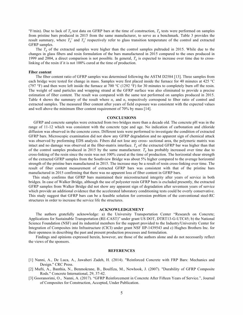
FIELD STRUCTURES Walker box-culvert bridge The Walker box-culvert bridge was constructed in 1999 on Walker Avenue in the City of Rolla, Missouri to replace the original bridge which was made of three concrete-encased corrugated steel pipes and became unsafe to operate due to excessive corrosion of the steel pipes. GFRP bars were implemented in the new bridge as an alternative for steel rebar in order to extend the service life beyond that of conventional steel-RC construction. The new bridge is 10.97 m (36 ft.) wide, consisting of eighteen 1.5 by 1.5 m (4.92 by 4.92 ft.) box culverts with a
3
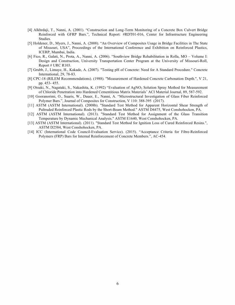
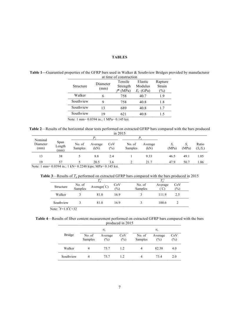
thickness of 150 mm (5.9 in.). The old and new bridges are shown in Fig. 1. The RC boxes were entirely reinforced with No.2 GFRP bars (nominal diameter of 6.3 mm) pre-bent and cut to size by the manufacturer. The 25.4 mm (1 in.) concrete cover was maintained using plastic wheel spacers. Fig. 2 shows a completed GFRP cage before concrete casting. Conventional concrete made of Portland cement, fly ash, tap water, and Missouri river aggregate with a maximum aggregate size of 9.5 mm (3/8 in.) were used to produce the units. The measured concrete compressive strength was 42.7 MPa (6.2 ksi) [4]. The GFRP bars used for the precast RC culverts were made of the E-glass fiber and polyester resin while E-CR glass fiber and vinyl ester resin were used in GFRP bars produced in 2015. The most important implication of this change in constituents over time (common among all North American pultruders) is that the durability of the resulting GFRP bars is greatly enhanced given the stability of both E-CR glass and vinyl ester compared to E-glass and polyester. The guaranteed properties of the bars used in Walker Bridge are shown in Table 1. Southview bridge Southview Bridge initially included four-cell steel reinforced concrete (RC) box-culverts (Fig. 3). The 250 mm (10 in.) thick RC bridge slab went through an expansion in 2004 which included the construction of an additional lane and a sidewalk [5]. The new deck was built on three conventional RC walls as for the existing structure. The concrete deck of the complementary part implemented Nos. 3, 4 and 6 GFRP bars (Fig 4) and No. 3 prestressed CFRP tendons [6]. The construction of the FRP reinforced slab, plus a 2 m (6.6 ft.) wide conventional RC sidewalk on the opposite side, allowed extending the overall width of the bridge from 3.9 m (12.8 ft.) to 11.9 m (39.0 ft.). The measured concrete compressive strength was 41.4 MPa (6 ksi). The guaranteed properties of the GFRP bars used in Southview Bridge is shown in Table 1. Both bridges operate under the following environmental conditions: thermal range of -6 to +32 °C (21 to 90 °F), wet and dry cycles, freeze-thaw cycles and exposure to de-icing salt.
SAMPLE EXTRACTION AND PREPARATION Technically-competent personnel performed the extraction of concrete cores from both bridges in 2016. Four
102 mm (4 in.) diameter concrete cores were extracted from the bottom of two culverts of Walker Bridge and two cores with similar size were extracted from the deck of the Southview Bridge. GFRP coupons were extracted from the cores (Fig. 5) and were sliced to an approximate width of 10 mm (0.4 in.) using a diamond saw for microscopic examination. The surface of the GFRP samples was prepared by sanding using different levels of sandpaper and employing polishing equipment. Fine polishing completed the specimen preparation using a wet-polishing agent and polycrystalline diamond paste. The specimens used in SEM imaging were also employed in EDS analysis. Additionally, the coupons were cut in appropriate sizes for horizontal shear strength, Tg and fiber content measurements.
CONCRETE CHARACTERIZATION
pH measurement
The pH was measured to provide a qualitative estimate of concrete alkalinity. The pH measurement approach proposed by Grubb and coworkers [7] was followed. First, the concrete surface at the depth of 25 to 51 mm (1 to 2 in.) of the cores was ground using sand paper and diluted in distilled water with 1:1 ratio. Then, the pH strip was used to evaluate the alkalinity of the solution. The procedure was performed in three different locations. pH values between 11 and 12 were measured for samples extracted from both bridges which meet expectation for the type and age of the concrete [7]. Carbonation depth
A carbonation depth equal to the concrete cover may be responsible for steel corrosion initiation. The carbonation depth was measured by spraying the 1% solution of phenolphthalein in 70% ethyl alcohol on freshly fractured concrete surfaces [8]. The colorless solution turned to pink/purple when the pH was higher than 9 and stayed colorless otherwise. No indication of concrete carbonation was observed using this method in samples from both bridges (Fig 6). While no carbonation of concrete can be considered beneficial to steel rebars because the pH remains at high values, the opposite is true for GFRP reinforcement that is more sensitive to high alkalinity. Thus, the GFRP bars extracted from these cores were subject to an aggressive alkaline environment over the 17 and 11 years of service for Walker and Southview bridge respectively.
4
Chloride diffusion measurement
An adaptation of the rapid migration test (RMT) using silver nitrate solution was employed to determine the chloride diffusion in the concrete samples. Two concrete samples were cut in order to provide fresh split surfaces. A 0.1 mol/L silver nitrate solution was poured on the entire cut surface [9]. In presence of chloride, a clearly visible white/silver precipitation takes place on the surface while in the absence of chlorides, the solution reacts with the hydroxides present in the concrete, changing the surface color to brown. No clear evidence of chloride diffusion was observed in all the tested specimens of both bridges using this method. It was noticed that the surface became darker, to a color similar to brown, while there was no visible gray area (Fig 7).
GFRP CHARACTERIZATION SEM imaging
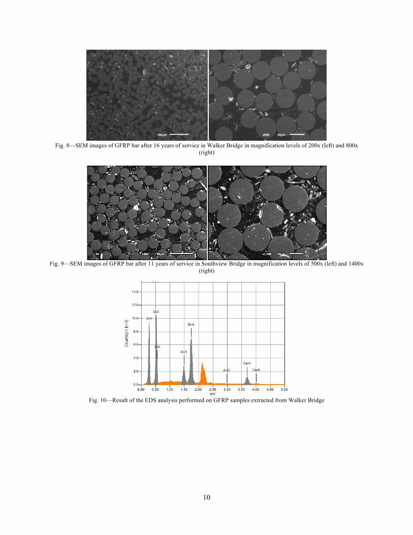
The GFRP microstructure was investigated since it is a critical parameter in performance and durability of GFRP bars [10]. The full cross-section of prepared GFRP coupons were scanned using SEM at different levels of magnification and images were taken at random locations. Attention was paid to the areas in the vicinity of the bar edges since possible degradation due to chemical attack starts at GFRP-concrete interface. Representative images are shown in Fig 8 and Fig 9. SEM analysis suggests that there was no apparent sign of deterioration in the GFRP coupons. No damage was observed in the matrix and at the matrix-fiber interface. Glass fibers appeared to be intact without no loss of cross-sectional area. EDS analysis
EDS was performed at several locations of each GFRP slices with a focus on the edge of the bar to identify existing chemical elements. Results are shown in Fig 10 and Fig 11 where the vertical axis corresponds to the counts (number of X-rays received and processed by the detector) and the horizontal axis presents the energy level of those counts. Si, Al, Ca (from glass fibers) and C (from the matrix) were the predominant chemical elements in the extracted samples. No apparent sign of any chemical attack was observed in the bars. Horizontal shear strength The horizontal shear strength of the extracted GFRP coupons was determined following ASTM D4475 [11] as a useful parameter for durability evaluation. The test was performed on three GFRP coupons extracted from Southview Bridge: i) one No. 4 GFRP bar with the total length of (58 mm) 2.3 in, and ii) two No. 6 GFRP bars with the total length of 76 mm (3 in.) and (74 mm) 2.9 in. No horizontal shear test was performed on samples extracted from Walker Bridge due to their small diameter. Since no historic data was available at the time of construction, the results were compared to the test performed on pristine bars produced by the same manufacturer in 2015 as a benchmark. Specimens were tested with the span-to-diameter ratio equal to three, according to standard and compared with pristine samples. The test was performed in displacement control with the rate of 1.27 mm/min (0.05 in/min) of the cross head (Fig 12). All three specimens presented the horizontal shear mode of failure and the shear strengths were determined following ASTM-D4475 as:
20.849 PSd
=
(1) where S is the horizontal shear strength, P refers to the breaking load and d corresponds to the nominal diameter of the specimen. A summary of the results is shown in Table 2 where Sc and Ss, refer to the shear strength of control samples tested in 2015 and extracted samples, respectively. The same notation is employed for the failure load. The extracted GFRP bars showed about 5% increase in horizontal shear strength compared to the samples produce in 2015. Since the horizontal shear is greatly affected by the property of the resin, the increase may be a result of resin crosslinking over time. Glass transition temperature (Tg)
The changes in Tg of the polymer matrix was determined by performing dynamic mechanical analysis (DMA) test on three specimens for each bridge. Rectangular specimens with dimensions of 1×5×50 mm (0.04×0.2×2.0 in.) were extracted from the bars according to ASTM E1640 [12]. The DMA test was performed with a three-point-bending fixture for a temperature ranging from 30 to 130 °C (86 to 266 °F), and a heating rate of 1 °C/min (1.8
5
°F/min). Due to lack of Tg test data on GFRP bars at the time of construction, Tg tests were performed on samples from pristine bars produced in 2015 from the same manufacturer, to serve as a benchmark. Table 3 provides the result summary, where Tg
c and Tgs respectively refer to glass transition temperature of the control and extracted
GFRP samples. The Tg of the extracted samples were higher than the control samples pultruded in 2015. While due to the
changes in glass fibers and resin formulation of the bars manufactured in 2015 compared to the ones produced in 1999 and 2004, a direct comparison is not possible. In general, Tg is expected to increase over time due to cross-linking of the resin if it is not 100% cured at the time of production. Fiber content
The fiber content ratio of GFRP samples was determined following the ASTM D2584 [13]. Three samples from each bridge were tested for change in mass. Samples were first placed inside the furnace for 40 minutes at 425 °C (797 °F) and then were left inside the furnace at 700 °C (1292 °F) for 30 minutes to completely burn off the resin. The weight of sand particles and wrapping strand at the GFRP surface was also eliminated to provide a precise estimation of fiber content. The result was compared with the same test performed on samples produced in 2015. Table 4 shows the summary of the result where αc and αs respectively correspond to fiber ratio of control and extracted samples. The measured fiber content after years of field exposure was consistent with the expected values and well above the minimum fiber content requirement of 70% by mass [14].
CONCLUSIONS GFRP and concrete samples were extracted from two bridges more than a decade old. The concrete pH was in the range of 11-12 which was consistent with the concrete type and age. No indication of carbonation and chloride diffusion was observed in the concrete cores. Different tests were performed to investigate the condition of extracted GFRP bars. Microscopic examination did not show any GFRP degradation and no apparent sign of chemical attack was observed by preforming EDS analysis. Fibers did not lose any cross- sectional area, the polymeric matrix was intact and no damage was observed at the fiber-matrix interface. Tg of the extracted GFRP bar was higher than that of the control samples produced in 2015 by the same manufacturer. Tg has probably increased over time due to cross-linking of the resin since the resin was not 100% cured at the time of production. The horizontal shear strength of the extracted GFRP samples from the Southview Bridge was about 5% higher compared to the average horizontal strength of the pristine bars manufactured in 2015. The increase may be a result of resin cross-linking over time. The result of fiber content measurement of extracted GFRP bars was consistent with that of the pristine bars manufactured in 2015 confirming that there was no apparent loss of fiber content in GFRP bars. This study confirms that GFRP bars maintained their microstructural integrity after years of service in both bridges. In case of Walker Bridge, although the use of polyester resin GFRP bars is excluded presently, the extracted GFRP samples from Walker Bridge did not show any apparent sign of degradation after seventeen years of service which provide an additional evidence that the accelerated laboratory conditioning tests could be overly conservative. This study suggest that GFRP bars can be a feasible solution for corrosion problem of the conventional steel-RC structures in order to increase the service life the structures.
ACKNOWLEDGEMENT The authors gratefully acknowledge: a) the University Transportation Center “Research on Concrete;
Applications for Sustainable Transportation (RE-CAST)” under grant US DOT, DTRT13-G-UTC45; b) the National Science Foundation (NSF) and its industrial members for the support provided to the Industry/University Center for Integration of Composites into Infrastructure (CICI) under grant NSF IIP-1439543 and c) Hughes Brothers Inc. for their openness in describing the past and present production processes and formulation.
Findings and opinions expressed herein, however, are those of the authors alone and do not necessarily reflect the views of the sponsors.
REFERENCES [1] Nanni, A., De Luca, A., Jawaheri Zadeh, H. (2014). "Reinforced Concrete with FRP Bars: Mechanics and
Design." CRC Press. [2] Mufti, A., Banthia, N., Benmokrane, B., Boulfiza, M., Newhook, J. (2007). "Durability of GFRP Composite
Rods." Concrete International, 29, 37-42. [3] Gooranorimi, O., Nanni, A. (2017). “GFRP Reinforcement in Concrete After Fifteen Years of Service.”, Journal
of Composites for Construction, Accepted, Under Publication.
6
[4] Alkhrdaji, T., Nanni, A. (2001). “Construction and Long-Term Monitoring of a Concrete Box Culvert Bridge Reinforced with GFRP Bars.”, Technical Report: #RDT01-016, Center for Infrastructure Engineering Studies.
[5] Holdener, D., Myers, J., Nanni, A. (2008). “An Overview of Composites Usage in Bridge Facilities in The State of Missouri, USA”, Proceedings of the International Conference and Exhibition on Reinforced Plastics, ICERP, Mumbai, India.
[6] Fico, R., Galati, N., Prota, A., Nanni, A. (2006). “Southview Bridge Rehabilitation in Rolla, MO – Volume I: Design and Construction, University Transportation Center Program at the University of Missouri-Roll, Report # URC R103.
[7] Grubb, J., Limaye, H., Kakade, A. (2007). "Testing pH of Concrete: Need for A Standard Procedure." Concrete International, 29, 78-83.
[8] CPC-18 (RILEM Recommendations). (1988). "Measurement of Hardened Concrete Carbonation Depth.", V 21, pp. 453- 455.
[9] Otsuki, N., Nagataki, S., Nakashita, K. (1992) “Evaluation of AgNO3 Solution Spray Method for Measurement of Chloride Penetration into Hardened Cementitious Matrix Materials˝ ACI Material Journal, 89, 587-592.
[10] Gooranorimi, O., Suaris, W., Dauer, E., Nanni, A. “Microstructural Investigation of Glass Fiber Reinforced Polymer Bars.”, Journal of Composites for Construction, V 110: 388-395 (2017).
[11] ASTM (ASTM International). (2008b). "Standard Test Method for Apparent Horizontal Shear Strength of Pultruded Reinforced Plastic Rods by the Short-Beam Method." ASTM D4475, West Conshohocken, PA.
[12] ASTM (ASTM International). (2013). "Standard Test Method for Assignment of the Glass Transition Temperature by Dynamic Mechanical Analysis." ASTM E1640, West Conshohocken, PA.
[13] ASTM (ASTM International). (2011). "Standard Test Method for Ignition Loss of Cured Reinforced Resins.", ASTM D2584, West Conshohocken, PA.
[14] ICC (International Code Council-Evaluation Service). (2015). “Acceptance Criteria for Fibre-Reinforced Polymers (FRP) Bars for Internal Reinforcement of Concrete Members.”, AC-454.
7
TABLES
Table 1—Guarantied properties of the GFRP bars used in Walker & Southview Bridges provided by manufacturer
at time of construction
Structure Diameter (mm)
Tensile Strength f* (MPa)
Elastic Modulus Ef (GPa)
Rapture Strain (%)
Walker 6 758 40.7 1.9 Southview 9 758 40.8 1.8 Southview 13 689 40.8 1.7 Southview 19 621 40.8 1.5
Note: 1 mm= 0.0394 in.; 1 MPa= 0.145 ksi. Table 2—Results of the horizontal shear tests performed on extracted GFRP bars compared with the bars produced
in 2015
Nominal Diameter
(mm)
Pc Ps Span
Length (mm)
No. of Samples
Average (kN)
CoV (%)
No. of Samples
Average (kN)
Sc (MPa)
Ss (MPa)
Ratio (Ss/Sc)
13 38 5 8.8 2.4 1 9.33 46.5 49.1 1.05
19 57 5 20.5 3.6 2 21.7 47.9 50.7 1.06 Note: 1 mm= 0.0394 in.; 1 kN= 0.2248 kips; MPa= 0.145 ksi.
Table 3—Results of Tg performed on extracted GFRP bars compared with the bars produced in 2015 Tg
c Tgs
Structure No. of Samples Average(°C) CoV
(%) No. of
Samples Average
(°C) CoV (%)
Walker 3 81.0 16.9 3 111.9 2.5
Southview 3 81.0 16.9 3 100.6 2
Note: °F=1.8°C+32
Table 4—Results of fiber content measurement performed on extracted GFRP bars compared with the bars produced in 2015
Bridge αc
αs
No. of Samples
Average (%)
CoV (%)
No. of Samples
Average (%)
CoV (%)
Walker 4 75.7 1.2 4 82.38 4.0
Southview 4 75.7 1.2 4 73.4 2.0
8
FIGURES
Fig. 1—Old (left) and new (right) Walker Bridge
Fig. 2—A complete GFRP cage before concrete casting
Fig. 3—A view of the former Southview Bridge
9
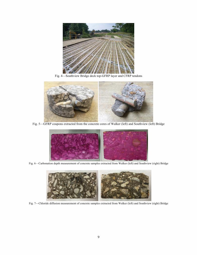
Fig. 4—Southview Bridge deck top-GFRP layer and CFRP tendons
Fig. 5—GFRP coupons extracted from the concrete cores of Walker (left) and Southview (left) Bridge
Fig. 6—Carbonation depth measurement of concrete samples extracted from Walker (left) and Southview (right) Bridge
Fig. 7—Chloride diffusion measurement of concrete samples extracted from Walker (left) and Southview (right) Bridge
10
Fig. 8—SEM images of GFRP bar after 16 years of service in Walker Bridge in magnification levels of 200x (left) and 800x
(right)
Fig. 9—SEM images of GFRP bar after 11 years of service in Southview Bridge in magnification levels of 500x (left) and 1400x
(right)
Fig. 10—Result of the EDS analysis performed on GFRP samples extracted from Walker Bridge
11
Fig. 11—Result of the EDS analysis performed on GFRP samples extracted from Southview Bridge
Fig. 12—Horizontal shear test performed on GFRP bars extracted from Southview Bridge


![GFRP [Resin Infusion]](https://img.pdfslide.us/doc/110x75/546e67d4af795971298b5642/gfrp-resin-infusion.jpg)


![GFRP [Hand lay up]](https://img.pdfslide.us/doc/110x75/557cb1dcd8b42abf328b4c0e/gfrp-hand-lay-up.jpg)