Embed Size (px)
Citation preview

Low Cost Linear Actuator
By:
Steven Parker & Rodney Arceneaux
Advisor: Dr. Patrick McDowell
Class Professor: Dr. Cris Koutsougeras
ET 494-01
Senior Design
Southeastern Louisiana University
Computer Engineering Technology
Purpose
Build a multi jointed mechanical arm using linear actuators to loads between 100 – 200
pounds. The arm will have reaction speed 15 to 18 inches per second and will be able to move
in a full retractable motion of a human arm. The arm movement will be controlled by an
Arduino. We will utilize multiple linear actuators and different speeds to emulate the motion of
an actual arm.
The actually actuator will be different from other common actuators found because it
will be able to pick up much heavier loads. The actuator will also be able to be controlled by the
Arduino and use sensors to know when to stop certain movements.
Abstract
An actuator is a type of motor that is responsible for moving or controlling mechanism
or a system. It can operate by many sources of energy typically electric current, hydraulics, or
pneumatic pressure. The actuator will be using runs on electric current and will be powered by
a motor that converts electric energy to mechanical torque.
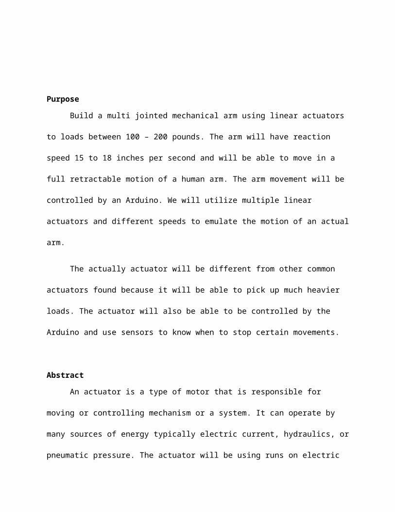
As with most linear actuators there are two distinct functional elements: one is the
provision for guidance of the moving rod and the other is the means of motion actuation. We
need to come up with a guidance method that will have a reliable linear motion system.
The project will aim to link multiple actuators together to implement the full joint
movement of an arm. The arm can be used to pick up loads that a person would not
reasonable want to pick up every day.
Objective
The goal for this semester was to fully design and operates the first actuator for the
arm. We planned to use a design from a similar actuator and make it more cost efficient for our
project. This semester was mainly used for troubleshooting any problems that may arise during
the construction of the first actuator. We also wanted the actuator to be fully controllable by
the Ardiuno by the end of the semester.
We want the Arduino to be able to control the actuator through the program interface.
We will also utilize a sensor to know how to stop certain movements from locking up the
actuator. We will end up mounting the sensor at an appropriate location as we work on the
final design of the prototype.
Design Description
The initial design for the actuator was taken from a blueprint we were referred to
online. In his design most of his parts were common appliances one could find at the local
hardware store. For are design we want to implement the same idea however we want are
actuator to pick up much heavier loads and possibly be more cost efficient (Anderson, 2013).

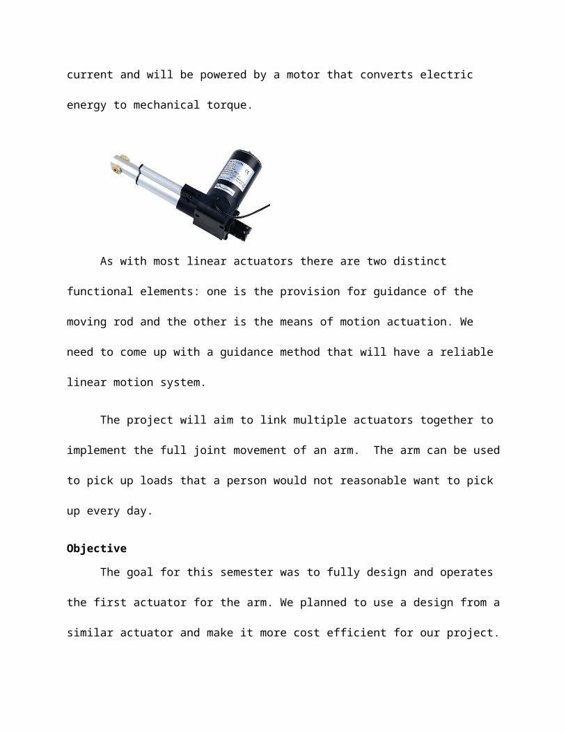
The original design would include mostly wooden parts similar to other actuators in a
much bigger scale. The actually design came out to about 22 inches. The rod for the actuator is
36 inches long and will be able to retract back and forth. The movements for the rod will be
held on track three threaded rods, so it transverse with ease as it moves.
The second design for the prototype had to change because the rod kept getting
jammed on the track with the threaded rod. It would severely affect the movements once we
would other things to the design. To remedy this we would take out the rod design and use rail
design instead similar to a shelf. We also decided to use a sensor on our design to restrict
certain movements. The sensors would be set to stop the rod from moving once it has moved
to close to the end of the track.
The final design for the actuator had to change because the threaded rod problem from
the previous design. The new design implemented a guided rail design to avoid any serious
jamming problems. The final design movements can also be tracked read more efficient by the
Arduino sensors. It is also more durable design and will be able to pick up much heavier loads at
a time.

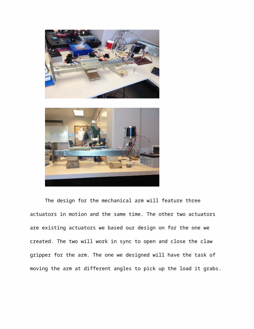
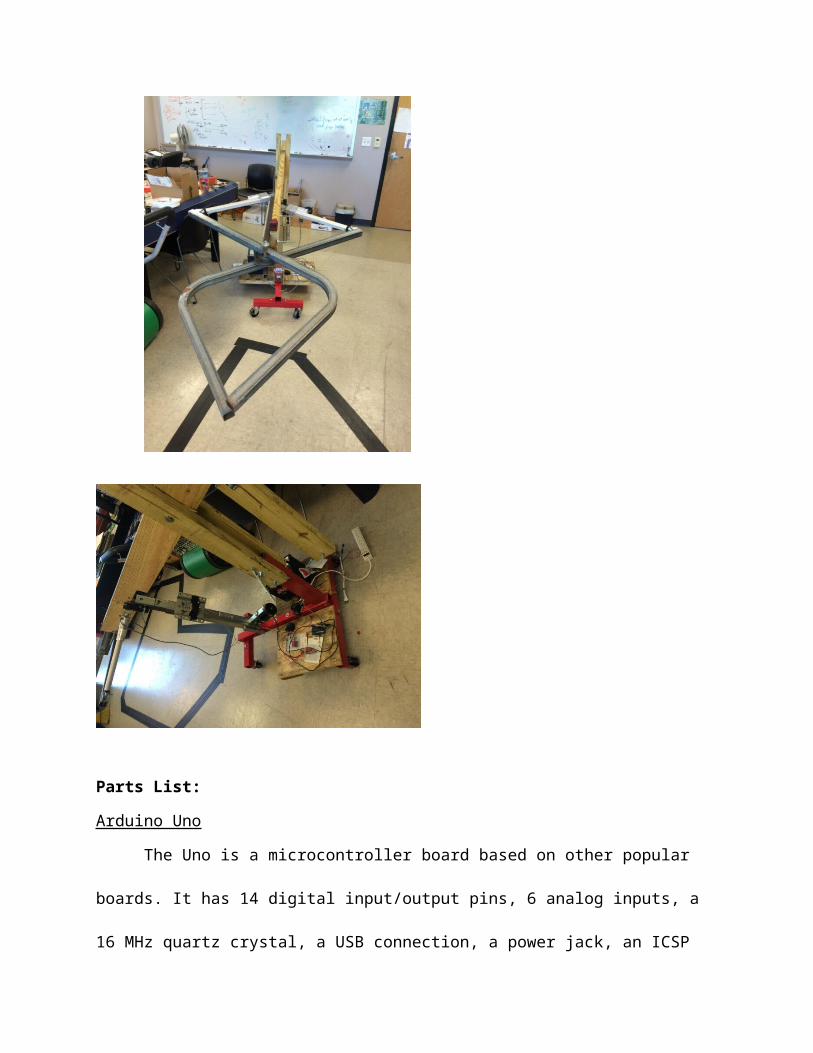
The design for the mechanical arm will feature three actuators in motion and the same
time. The other two actuators are existing actuators we based our design on for the one we
created. The two will work in sync to open and close the claw gripper for the arm. The one we
designed will have the task of moving the arm at different angles to pick up the load it grabs.
Parts List:
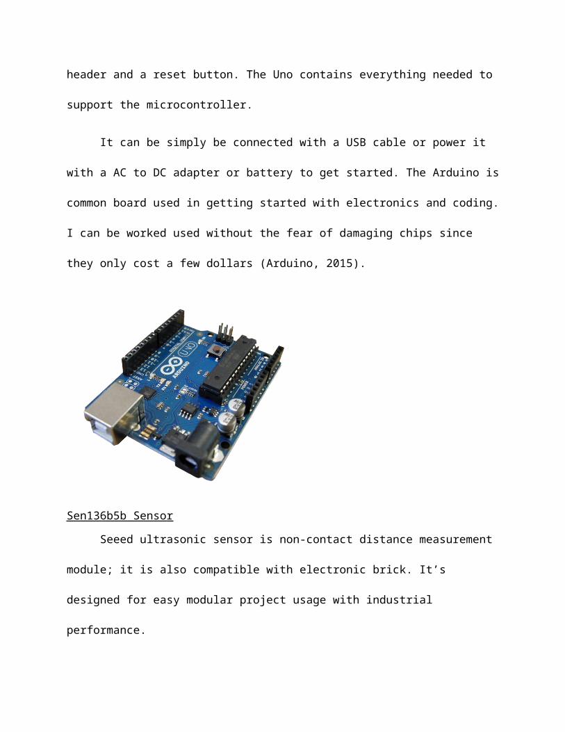
Arduino Uno
The Uno is a microcontroller board based on other popular boards. It has 14 digital
input/output pins, 6 analog inputs, a 16 MHz quartz crystal, a USB connection, a power jack, an
ICSP header and a reset button. The Uno contains everything needed to support the
microcontroller.
It can be simply be connected with a USB cable or power it with a AC to DC adapter or
battery to get started. The Arduino is common board used in getting started with electronics
and coding. I can be worked used without the fear of damaging chips since they only cost a few
dollars (Arduino, 2015).
Sen136b5b Sensor
Seeed ultrasonic sensor is non-contact distance measurement module; it is also
compatible with electronic brick. It’s designed for easy modular project usage with industrial
performance.
A short ultrasonic pulse is transmitted at the time 0, reflected by an object. The senor
receives this signal and converts it to an electric signal. The next pulse can be transmitted when
the echo is faded away. The recommend cycle period should be no less than 50ms. If a 10μs
width trigger pulse is sent to the signal pin, the Ultrasonic module will output eight 40kHz
ultrasonic signal and detect the echo back. If no obstacle is detected, the output pin will give a
38ms high level signal (Seeed, 2015).
Specifications
Supply Voltage: 5VGlobal Current Consumption: 15mAUltrasonic Frequency: 40k HzMaximal Range: 400 cmMinimal Range: 3 cmResolution: 1 cm
Trigger Pulse Width: 10 µsOutline Dimension: 43x20x15 mm
Victor 884
The Victor 884 motor controller is specifically engineered for robotic usage. It has a high
current capacity, a low voltage drop, and a peak surge capacity make it ideal for drive systems.
Its braking options and precise controls make meeting controls for arms and lift systems while
taking up minimal work. I also have a protective coating to shield the components from any
debris (Vex, 2015).
Specifications
Nominal Voltage: 12VMin/Max Voltage: 6-15VContinuous Current: 60A
Surge Current (2 sec): 150APWM Input Pulse (high time): 1-2 ms nominal, 0.87-2.14 ms maxPWM Input Rate (period): 2.1-500 msPWM Output Chop Rate: 1 KHzMinimum Throttle: 5.4%Fan Voltage Range: 6V - 16V

CIM DC Motor
Dimensions
• Diameter: 6.2cm• Length (without shaft): 11.2cm• Shaft Length: 3.3cm• Shaft Diameter: 8mm
Specifications
• Voltage range: 12V or less• Nominal Voltage: 12V• Stall Torque: 343oz-in• Stall Current: 115A• Kt: 2.98oz-in/A• Kv: 442.5 rpm/V• Efficiency: 65%

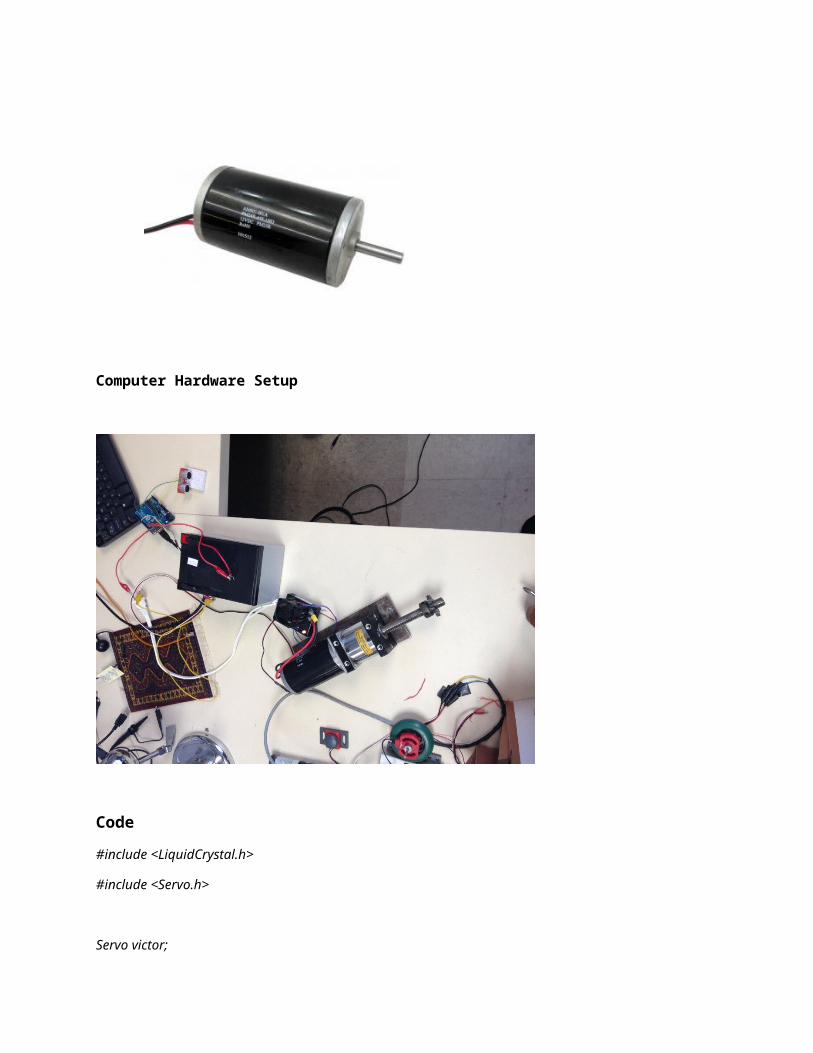
Computer Hardware Setup
Code
#include <LiquidCrystal.h>
#include <Servo.h>
Servo victor;

Servo victor2;
LiquidCrystal lcd(8, 9, 4, 5, 6, 7); // select the pins used
// define some values used by the panel and buttons
int lcd_key = 0;
int adc_key_in = 0;
const int pingPin = A1;
long duration, inches, cm;
char letter;
void setup() {
// put your setup code here, to run once:
pinMode(13,OUTPUT);
digitalWrite(13,LOW);
Serial.begin(9600);
victor.attach(A5);
victor2.attach(A4);
lcd.begin(16, 2); // start the library
lcd.setCursor(0,0); // set the LCD cursor position
lcd.print("Distance"); // print a simple message on the LCD
}
void loop() {
// put your main code here, to run repeatedly
long duration, inches, cm;
pinMode(pingPin, OUTPUT);
digitalWrite(pingPin, LOW);
delayMicroseconds(2);
digitalWrite(pingPin, HIGH);
delayMicroseconds(5);
digitalWrite(pingPin, LOW);
pinMode(pingPin, INPUT);
duration = pulseIn(pingPin, HIGH);
// convert the time into a distance
inches = microsecondsToInches(duration);
cm = microsecondsToCentimeters(duration);
Serial.print(inches);
Serial.print("in, ");
Serial.print(cm);
Serial.print("cm");
Serial.println();
lcd.print(cm);
lcd.print("cm");
delay(100);
lcd.setCursor(9,1); // move cursor to second line "1" and 9 spaces over
lcd.print(millis()/1000); // display seconds elapsed since power-up

lcd.setCursor(0,1); // move to the begining of the
if(Serial.available() > 0)
{
char letter = Serial.read();
if (letter == 'w') { //up
victor.writeMicroseconds(1000);
}
if (letter == 's') { //down
victor.writeMicroseconds(2000); // forward
}
if (letter == 'x') { // stop
victor.writeMicroseconds(1500); // stop
victor2.writeMicroseconds(1500);
}
if (letter == 'a') { //open
victor2.writeMicroseconds(2000); // forward
}

if (letter == 'd') { //close
victor2.writeMicroseconds(1000); // forward
}
}
}
long microsecondsToInches(long microseconds) {
return microseconds / 74 / 2;
}
long microsecondsToCentimeters(long microseconds) {
return microseconds / 29 / 2;
}
Deliverables
1. Come up with a design that will utilize the actuators in a full arm join movement.(September – Mid-October 2015) 3 weeks - Complete
2. Research and order parts necessary for designing first actuator.(Mid-October - Mid-November 2015) 3 weeks - Complete
3. Utilize equipment to build prototype actuator.(Mid-November – December 2015) 9 weeks - Complete
4. Independent research on design and additional materials. (December – January 2015) 5 weeks - Complete
5. Implement design on connecting multiple actuators together.(January – March 2015) 9 weeks – Complete
6. Build arm and perform testing.(March – April 2015) 9 weeks – Complete

Conclusion
Over the course of the last two semesters we have been perfected the design for the
actuator and the final design for the arm. We know have the arm up and running and it will be
able to pick up loads. The troubleshooting part of the project took much longer than expected.
It took us awhile to figure out our power connection problems, we have to find a way around
feeding different power sources to the arms parts. We also have to use another Arduino and
the micro controller to control the additional actuators. We managed to finish the software side
of the project in this semester successfully and we know how to construct the actuators
movements. We just need to properly control all actuators movements at out command at
anytime through the Arduino. Testing of the project let us realize that to pick up much heavier
loads we would need a counter balance at the other end of the arm. We really appreciated Dr.
McDowell ongoing help with assisting us with this project.

Works Cited
Anderson, Ian. "Home Built DIY 3 DOF Flight Simulator Movement Cockpit - Home Built DIY Linear
Actuator.." Home Built DIY 3 DOF Flight Simulator Movement Cockpit - Home Built DIY Linear
Actuator..BFF Design, 2013. Web. 02 Dec. 2015.
Arduino. "Arduino - ArduinoBoardUno." Arduino - ArduinoBoardUno. Arduino, 2015. Web. 02 Dec.
2015.
Seeed, Studio. "Ultra Sonic Range Measurement Module." - Wiki. Seeed Studio, 2015. Web. 02 Dec.
2015.
VEX, Robotics. "CIM Motor." VEX Robotics. VEX, 2015. Web. 2 Dec. 2015.


![[Senior Design] Advisor: Dr. Mitra Fall of 2014 Finale ...csit.selu.edu/~csit/seniorprojects/SeniorProjects... · The project will investigate friction stir welding (FSW) beginning](https://img.pdfslide.us/doc/110x75/5e861777ddb48b56cb3b8408/senior-design-advisor-dr-mitra-fall-of-2014-finale-csitselueducsitseniorprojectsseniorprojects.jpg)


![csit/seniorprojects/SeniorProjects... · Web view2020. 5. 9. · Where provided, the manual fire alarm box shall not be located in an area that is accessible to the public. [F]](https://img.pdfslide.us/doc/110x75/6132f703dfd10f4dd73ac8e3/csitseniorprojectsseniorprojects-web-view-2020-5-9-where-provided-the.jpg)