Embed Size (px)
Citation preview
Wireless Door Lock System
ET 493
Spring 2018
By: Kyle Rudolph, Brandon Gonlag, and Channing Maher
Advisor: Dr.Mohammad
Professor: Dr.Koutsougeras
Abstract:
This project requires that we build a door system that wirelessly interfaces with other
devices that can control its operation (lock and unlock). For this project we will use a
microcontroller programmed to act as a combination lock system. Inputs for the lock system will
be handled by an Android based application. Once the user correctly inputs the right code to
unlock the system, a deadbolt lock will disengage. Allowing the door to be opened. If the user
inputs the wrong code, the system will reset until the code is correctly entered. If the password is
incorrectly entered to many time, an alarm will be triggered.
Introduction and Goals:
This project uses a Bluetooth module with an Arduino Nano and the locking logic will be
programmed into the Nano. This is our plans from the beginning of the semester:
● Develop a prototyped lock system
● Build a circuit to act as a lock/unlock system
● Create a hardware setup for Bluetooth access
● Interface the system with Android devices using a phone App that will be created for this
purpose
Design and Materials:
Parts List:
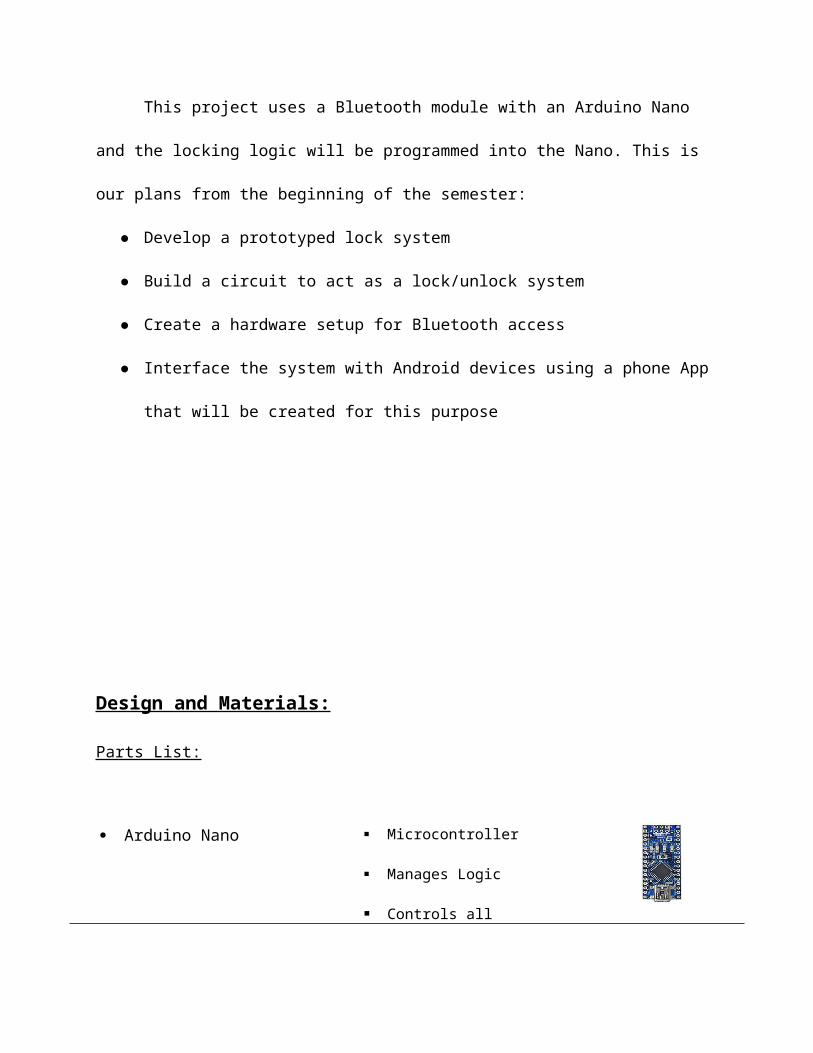
Arduino Nano Microcontroller
Manages Logic
Controls all components
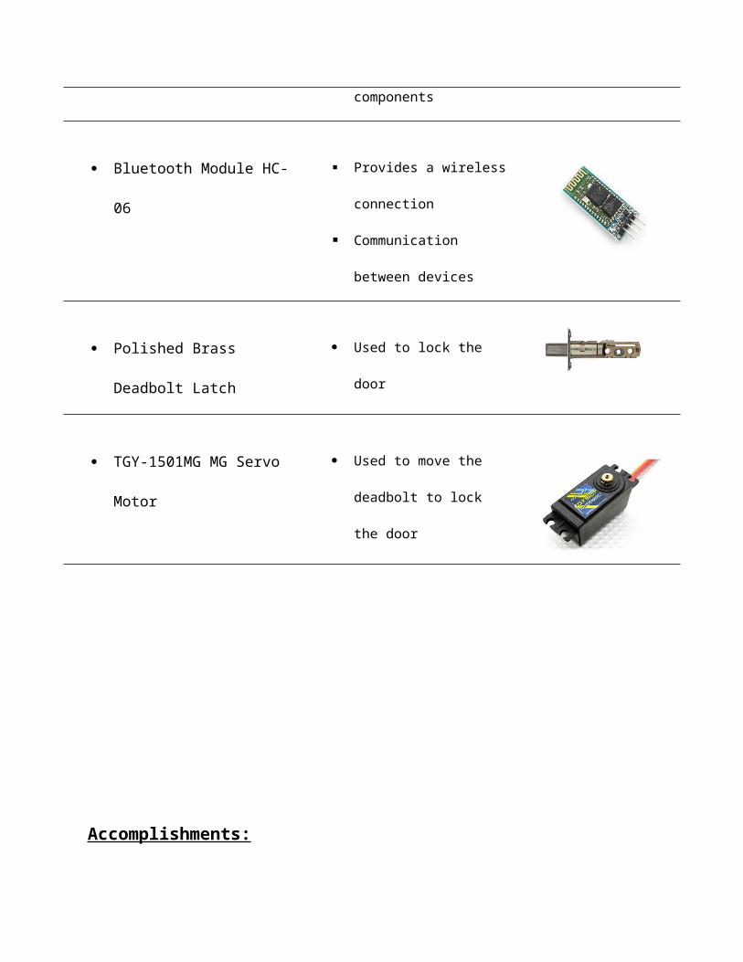
Bluetooth Module HC-06 Provides a wireless
connection
Communication between
devices
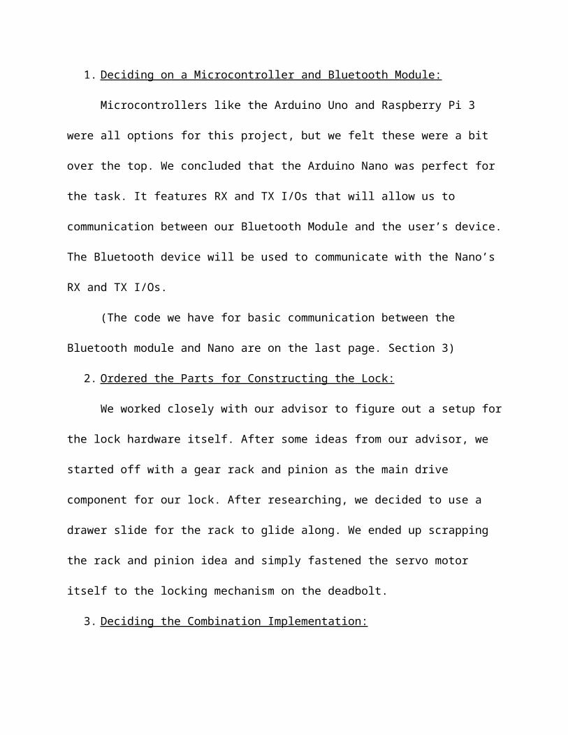
Polished Brass Deadbolt Latch Used to lock the door
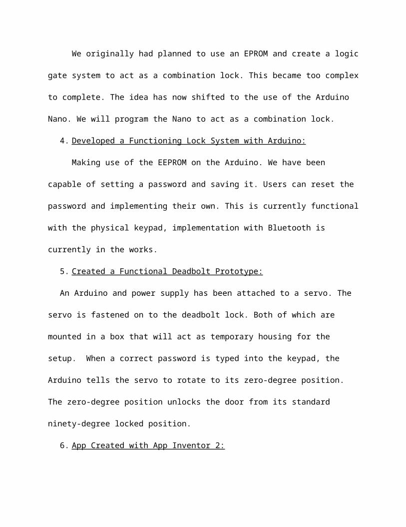
TGY-1501MG MG Servo
Motor
Used to move the deadbolt
to lock the door
Accomplishments:
1. Deciding on a Microcontroller and Bluetooth Module:
Microcontrollers like the Arduino Uno and Raspberry Pi 3 were all options for this
project, but we felt these were a bit over the top. We concluded that the Arduino Nano was
perfect for the task. It features RX and TX I/Os that will allow us to communication between our
Bluetooth Module and the user’s device. The Bluetooth device will be used to communicate with
the Nano’s RX and TX I/Os.
(The code we have for basic communication between the Bluetooth module and Nano are
on the last page. Section 3)
2. Ordered the Parts for Constructing the Lock:
We worked closely with our advisor to figure out a setup for the lock hardware itself.
After some ideas from our advisor, we started off with a gear rack and pinion as the main drive
component for our lock. After researching, we decided to use a drawer slide for the rack to glide
along. We ended up scrapping the rack and pinion idea and simply fastened the servo motor
itself to the locking mechanism on the deadbolt.
3. Deciding the Combination Implementation:
We originally had planned to use an EPROM and create a logic gate system to act as a
combination lock. This became too complex to complete. The idea has now shifted to the use of
the Arduino Nano. We will program the Nano to act as a combination lock.
4. Developed a Functioning Lock System with Arduino:
Making use of the EEPROM on the Arduino. We have been capable of setting a
password and saving it. Users can reset the password and implementing their own. This is
currently functional with the physical keypad, implementation with Bluetooth is currently in the
works.
5. Created a Functional Deadbolt Prototype:
An Arduino and power supply has been attached to a servo. The servo is fastened on to the
deadbolt lock. Both of which are mounted in a box that will act as temporary housing for the
setup. When a correct password is typed into the keypad, the Arduino tells the servo to rotate to
its zero-degree position. The zero-degree position unlocks the door from its standard ninety-
degree locked position.
6. App Created with App Inventor 2:
An application for Android devices has been developed. The current app is not functional
with the Arduino just yet. Further research into Bluetooth communication is needed to properly
send signals through the HC-06 to Arduino.
Individual Progress:
● Channing - Researched how to use and implement Bluetooth connectivity. Researching
app development. Deciding on a microcontroller.
○ A simple construction of the microcontroller to the Bluetooth device has been
built.
○ Developing an application with App Inventor 2 has made progress. Improvement
for the app is currently planned for next semester.
(Image of current appearance of app, Section 1 in bottom of paper)
○ Using block code to program the app to function and deliver wireless signals via
Bluetooth.
(Block Code, Section 2 in bottom of paper)
○ Code to properly have the app and the Arduino communicating is currently being
developed to work with the already created lock system code.
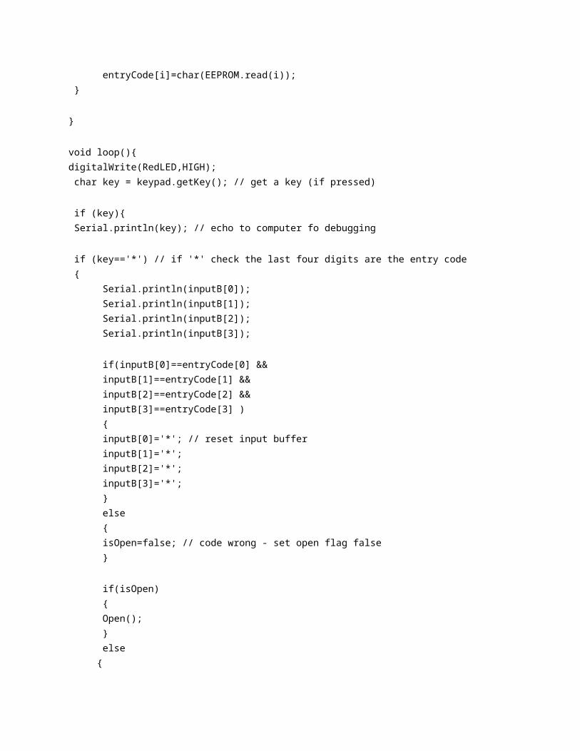
(Current rough look of code, Section 4 in bottom of paper)
● Brandon – Created a working deadbolt prototype by fastening a servo motor to the
locking mechanism of a deadbolt lock. Worked with Kyle to get the servo running with
the keypad program. Completed a functional locking mechanism that works with a
microcontroller.
○ Developed a small prototype box to simulate as the inside of the door lock.
○ Helped wire the Arduino to the servo controlling the deadbolts locking system.
○ Working with team to finish goals and improve the project.
● Kyle – Building the circuit for the wireless door lock and getting the EEPROM to interact
with the keypad. Doing research on the best way to save passwords to EEPROM.
○ Built 3x4 keypad using buttons and OR gates connected to LEDs to be able to
read if the zero to nine is being read. We did this to see what values are being read
to the EPROM.
○ When trying to get the EEPROM working we came across with problems of how
to store the new 4-digit passwords to the EEPROM without programming it.
○ When working on the EEPROM we decide it was taking up too much time and
went to Arduino. When working on the Arduino first task was to make LED
blink. When typing in the four-digit password it would make a green LED blink
three times and pressing the * button to confirm the password. When the four-
digit password was wrong it would make the red LED blink four times.
○ The next task was to be able to change the current password to a new password
and by pressing the # button to change the password. When changing the
password both LED will blink back and forth with each other three time to let the
user know the password was changed. The problem we encounter was when
changing to the new password when turning off the Arduino and turning it back
on it wouldn’t save the new password and when turning it back on it would rest to
the original password that we put into the code.
○ The task now was to find a way to be able to save the new current password to the
Arduino when it turns off. When working on the code we decide to use the
EEPROM library to write the current password word we have and when we
changed the current password. It will store it in the memory of the Arduino so
when it turns off it will turn off and turns back on it will keep the user password.
○ The next thing we did was combine the keypad part and the servo part to see if the
project works together and to see if the servo and lock work together.
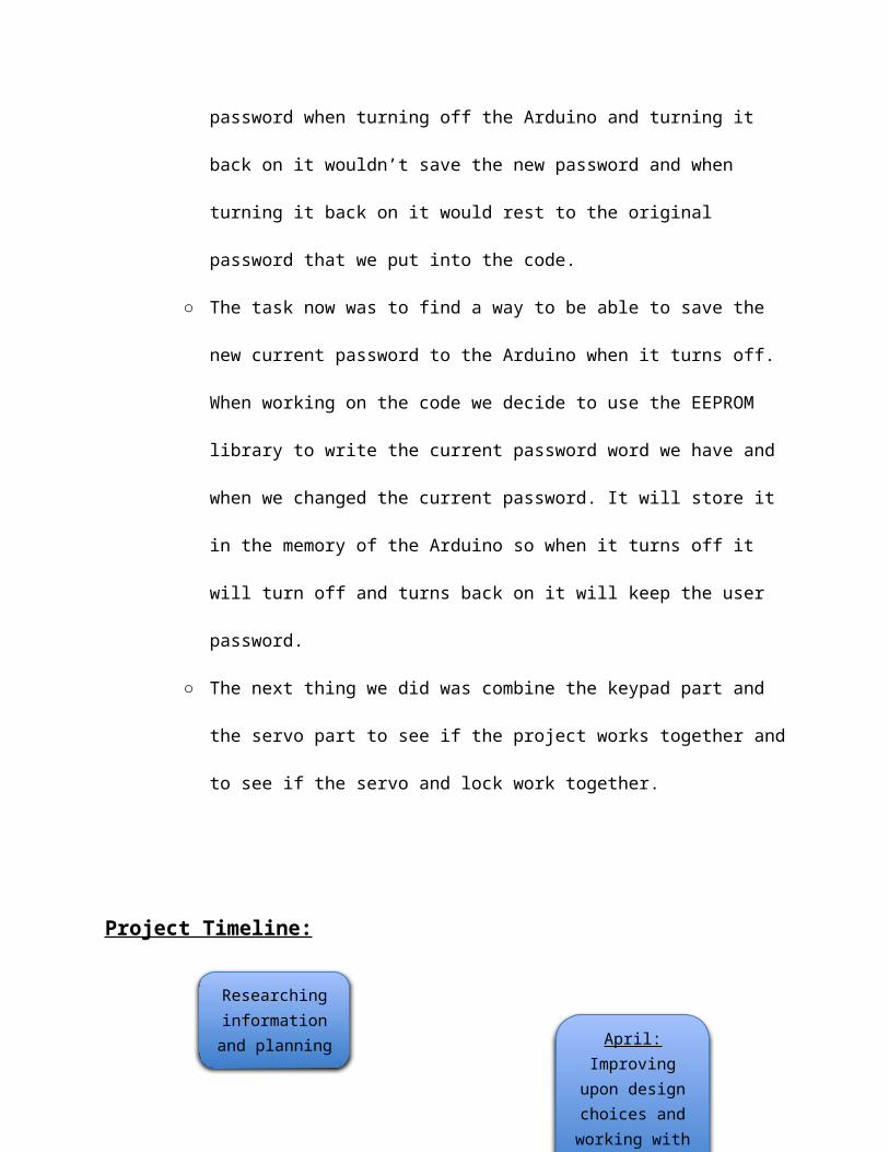
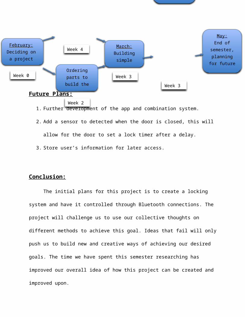
Project Timeline:
February:Deciding on a
project
Week 0
Week 4
Week 2
Ordering parts to build the project
Researching information and
planning
March:Building simple
prototypes
Week 3Week 3
April:Improving upon design choices
and working with App
Development
May:End of
semester, planning for
future progress
Future Plans:
1. Further development of the app and combination system.
2. Add a sensor to detected when the door is closed, this will allow for the door to set a lock
timer after a delay.
3. Store user’s information for later access.
Conclusion:
The initial plans for this project is to create a locking system and have it controlled
through Bluetooth connections. The project will challenge us to use our collective thoughts on
different methods to achieve this goal. Ideas that fail will only push us to build new and creative
ways of achieving our desired goals. The time we have spent this semester researching has
improved our overall idea of how this project can be created and improved upon.
Code/Images/Examples Section:
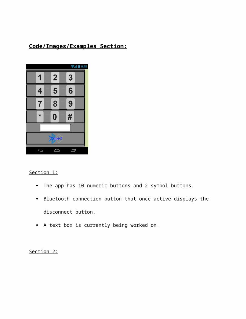
Section 1:
The app has 10 numeric buttons and 2 symbol buttons.
Bluetooth connection button that once active displays the disconnect button.
A text box is currently being worked on.
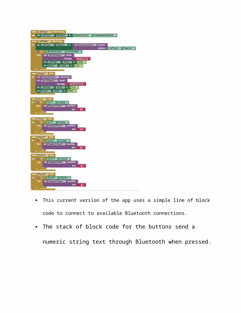
Section 2:
This current version of the app uses a simple line of block code to connect to available
Bluetooth connections.
The stack of block code for the buttons send a numeric string text through
Bluetooth when pressed.
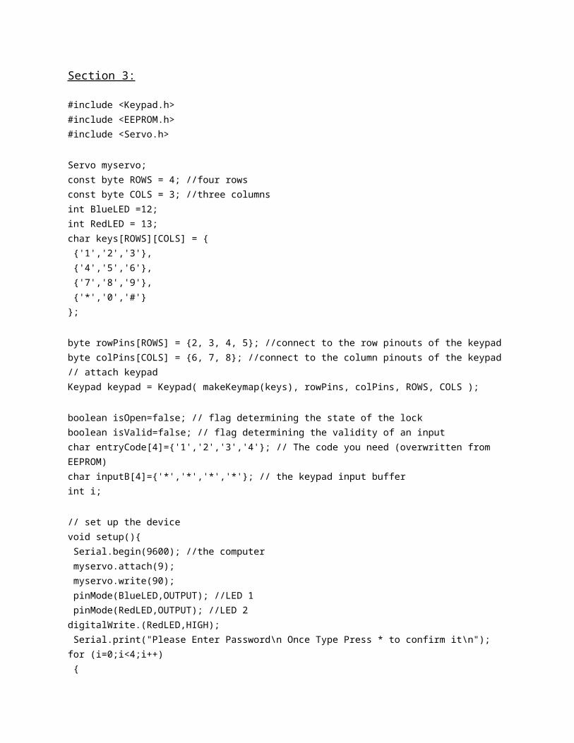
Section 3:
#include <Keypad.h>#include <EEPROM.h>#include <Servo.h> Servo myservo;const byte ROWS = 4; //four rowsconst byte COLS = 3; //three columnsint BlueLED =12;int RedLED = 13;char keys[ROWS][COLS] = { {'1','2','3'}, {'4','5','6'}, {'7','8','9'}, {'*','0','#'}}; byte rowPins[ROWS] = {2, 3, 4, 5}; //connect to the row pinouts of the keypadbyte colPins[COLS] = {6, 7, 8}; //connect to the column pinouts of the keypad// attach keypadKeypad keypad = Keypad( makeKeymap(keys), rowPins, colPins, ROWS, COLS ); boolean isOpen=false; // flag determining the state of the lockboolean isValid=false; // flag determining the validity of an inputchar entryCode[4]={'1','2','3','4'}; // The code you need (overwritten from EEPROM)char inputB[4]={'*','*','*','*'}; // the keypad input bufferint i; // set up the devicevoid setup(){ Serial.begin(9600); //the computer myservo.attach(9); myservo.write(90); pinMode(BlueLED,OUTPUT); //LED 1 pinMode(RedLED,OUTPUT); //LED 2digitalWrite.(RedLED,HIGH); Serial.print("Please Enter Password\n Once Type Press * to confirm it\n");for (i=0;i<4;i++)
{entryCode[i]=char(EEPROM.read(i));
} } void loop(){digitalWrite(RedLED,HIGH); char key = keypad.getKey(); // get a key (if pressed) if (key){ Serial.println(key); // echo to computer fo debugging if (key=='*') // if '*' check the last four digits are the entry code {
Serial.println(inputB[0]);Serial.println(inputB[1]);Serial.println(inputB[2]);Serial.println(inputB[3]);
if(inputB[0]==entryCode[0] &&inputB[1]==entryCode[1] &&inputB[2]==entryCode[2] &&inputB[3]==entryCode[3] ){
inputB[0]='*'; // reset input buffer inputB[1]='*'; inputB[2]='*'; inputB[3]='*'; } else { isOpen=false; // code wrong - set open flag false } if(isOpen) { Open(); } else { Close(); } Serial.print("To Change Password Type Current password and Press the #\n"); } else { // a key other than '*' has been pressed
if (isOpen && key=='#') { ValidCk(); Serial.print("The Password Changed\n"); } else { for (i=0;i<3;i++) { inputB[i]=inputB[i+1]; // you lose the first key } inputB[3]=key; // add the new key at the end } } }}void ValidCk(){ for (i=0;i<4;i++) if(inputB[i]=='*' || inputB[i]=='#') isValid=false; if (isValid) { for (i=0;i<4;i++) { entryCode[i]=inputB[i]; // copy contents of input EEPROM.write(i,entryCode[i]); // write the values in the EEPROM so they stay } for (i=0;i<4;i++) { digitalWrite(BlueLED,LOW); digitalWrite(RedLED,HIGH); delay(500); digitalWrite(BlueLED,HIGH); digitalWrite(RedLED,LOW); delay(500); } }}void Open(){ Serial.print("Door is Unlocked"); myservo.write(0); digitalWrite(BlueLED,HIGH); delay(500); digitalWrite(BlueLED,LOW); delay(500); digitalWrite(BlueLED,HIGH);
delay(500); digitalWrite(BlueLED,LOW); delay(500); digitalWrite(BlueLED,HIGH); delay(500); digitalWrite(BlueLED,LOW); myservo.write(90); }void Close(){ myservo.write(90);
digitalWrite(BlueLED,LOW); digitalWrite(RedLED,HIGH); delay(500); digitalWrite(RedLED,LOW); delay(500); digitalWrite(RedLED,HIGH); delay(500); digitalWrite(RedLED,LOW); delay(500); digitalWrite(RedLED,HIGH); myservo.write(90); Serial.print("The Door is Locked"); }
Section 4:
String inByte[5];int i;String inputString;char junk;int c1; //only to determine the amount of inputs for inByte, range is 5. #-num-num-num-num
void setup() { Serial.begin(9600);}
void loop() { userInput();}
void userInput(){ if(Serial.available())// Scanning for an input to equal true { for(i=0;i<=5;i++)
{ while(Serial.available())// Scanning for an input to equal true to start loop { char inChar = (char)Serial.read(); //read the input inByte[c1] += inChar; //make a string of the characters coming on serial Serial.println(); // inByte[c1] = inputString;// Serial.println(inByte[c1]); c1++;// Counter only used to navigate array } Serial.println(inByte[i]); } if(c1 == 5)// once key inputs equal 5, start reset for new inputs { for(i=0;i<=5;i++)// for loop to reset key inputs { inByte[i] = ""; } } }}