Embed Size (px)
Citation preview

802.11 Wireless LAN ProtocolCS 571
Fall 2006
© 2006 Kenneth L. CalvertAll rights reserved

Wireless Channel Considerations
• Stations may move– Changing propagation delays, signal strengths, etc.
• "Non-transitive" reception– A can hear B, B can hear C, but A cannot hear C
• No "collision detection"!– Detect unsuccessful transmission by absence of
acknowledgement
A
B
C
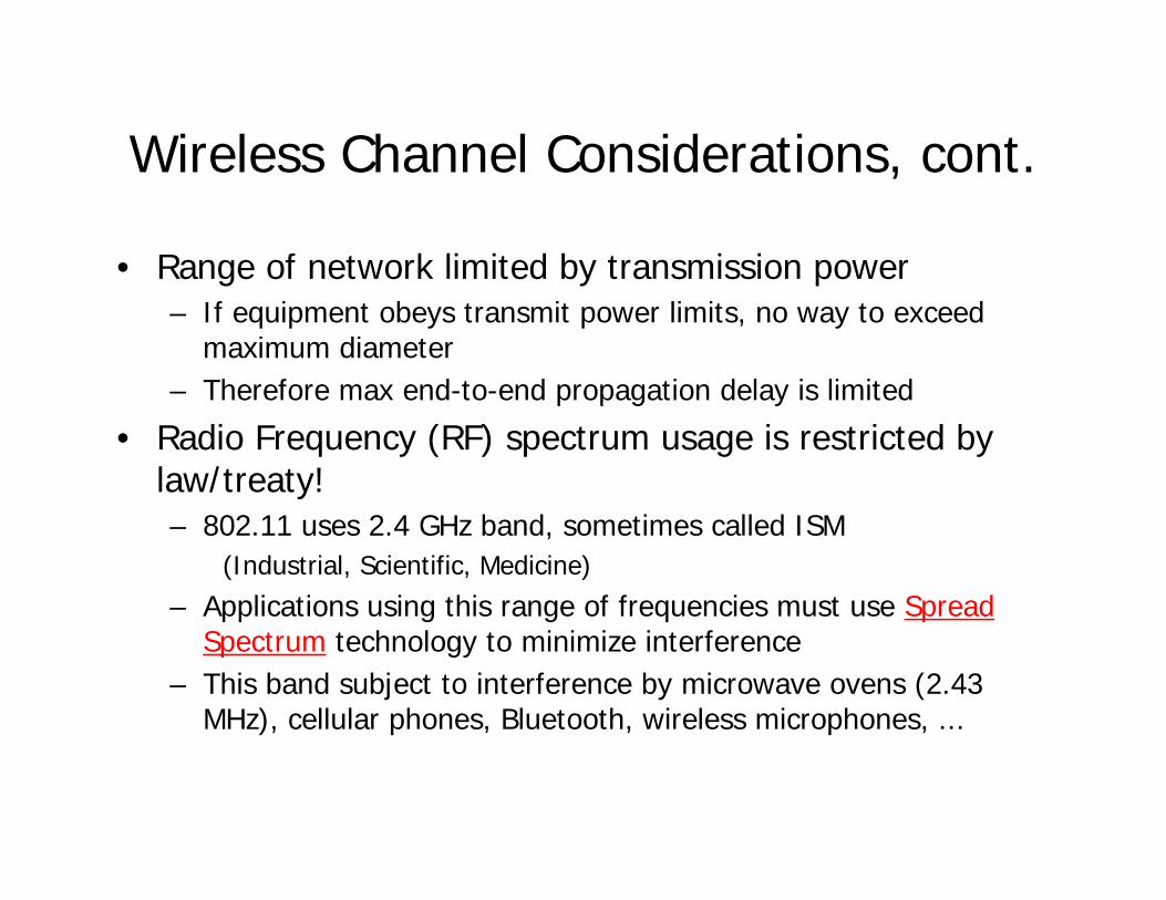
Wireless Channel Considerations, cont.
• Range of network limited by transmission power– If equipment obeys transmit power limits, no way to exceed
maximum diameter– Therefore max end-to-end propagation delay is limited
• Radio Frequency (RF) spectrum usage is restricted by law/treaty!– 802.11 uses 2.4 GHz band, sometimes called ISM
(Industrial, Scientific, Medicine)
– Applications using this range of frequencies must use Spread Spectrum technology to minimize interference
– This band subject to interference by microwave ovens (2.43 MHz), cellular phones, Bluetooth, wireless microphones, ...

Pieces of the 802.11 Standard
Medium Access Control divided into two parts– Distributed Coordination Function (DCF)
• Symmetric, all stations (including APs) behave the same way• Carrier Sense Multiple Access with Collision Avoidance (CSMA/CA)
• Stations contend for access to medium– Optional Point Coordination Function (PCF)
• Built on DCF• Allows periods of contention-free operation interleaved with
periods of contention• One station (typically AP) polls others to control who
transmits– Note: importance of association function
• Permits more efficient operation under heavy loads
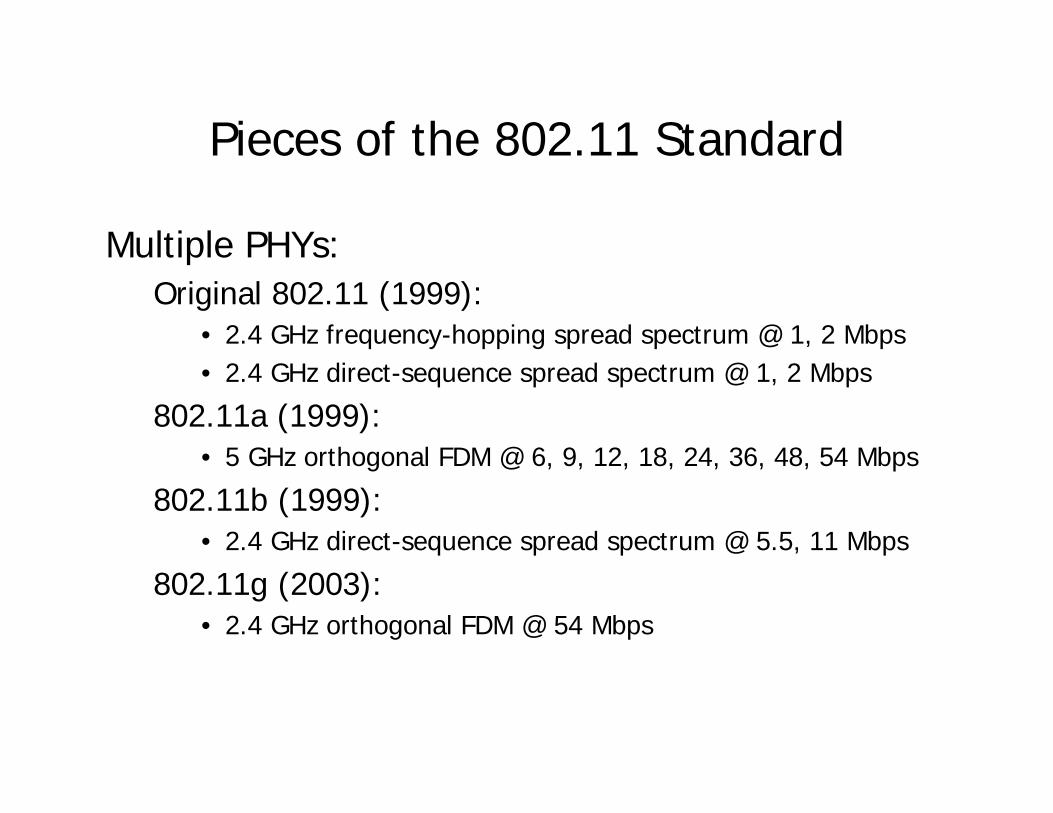
Pieces of the 802.11 Standard
Multiple PHYs:Original 802.11 (1999):
• 2.4 GHz frequency-hopping spread spectrum @ 1, 2 Mbps• 2.4 GHz direct-sequence spread spectrum @ 1, 2 Mbps
802.11a (1999):• 5 GHz orthogonal FDM @ 6, 9, 12, 18, 24, 36, 48, 54 Mbps
802.11b (1999):• 2.4 GHz direct-sequence spread spectrum @ 5.5, 11 Mbps
802.11g (2003):• 2.4 GHz orthogonal FDM @ 54 Mbps

Architecture: Components
stations
Distribution System (DS)
access points (APs)
How this works is notpart of IEEE 802.11!
BSS
BSSBSS = "Basic Service Set"
≈ A group of stationscommunicating

MAC Protocol Design
• Different stations perceive events differently⇒ Include explicit information about MAC state in transmitted
framesE.g., duration of the next frame to be transmittedBeacon frames inform stations about operational parameters
• Collision avoidance:• Stations choose a random backoff interval before colliding!
(Compare to CSMA/CD: backoff only after colliding)• Each station's backoff continues after other transmitted frames
(Helps with fairness)• No collision detection: waste whole frames in collisions
⇒ Try to ensure collisions don't happen long framesExchange (short) control frames to clear the channel (RTS-CTS)
⇒ Include immediate ACKs as part of MAC protocol — retransmit if no ACK received

802.11 MAC Protocol Services
• Contention-based Channel Access– Some collisions may occur (but — "collision avoidance")
• Contention-free Channel Access (optional)– No collisions (requires AP)
• Authentication of stations joining a network– "Open System" = any station can be authenticated
• Confidentiality of data– Using WEP or WPA encryption
• Association with a particular network ("BSS")• MAC-level Acknowledgements• Fragmentation and Reassembly
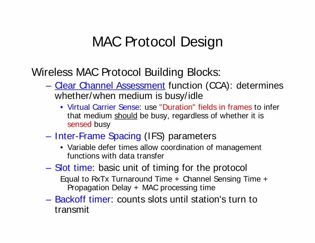
MAC Protocol Design
Wireless MAC Protocol Building Blocks:– Clear Channel Assessment function (CCA): determines
whether/when medium is busy/idle• Virtual Carrier Sense: use "Duration" fields in frames to infer
that medium should be busy, regardless of whether it is sensed busy
– Inter-Frame Spacing (IFS) parameters• Variable defer times allow coordination of management
functions with data transfer– Slot time: basic unit of timing for the protocol
Equal to RxTx Turnaround Time + Channel Sensing Time + Propagation Delay + MAC processing time
– Backoff timer: counts slots until station's turn to transmit

Basic DCF MAC Protocol
Basic Time Parameters– Slot Time: basic unit of backoff algorithm
= Time required for station to sense end of frame, start transmitting, and beginning of frame to propagate to others
– SIFS: Short Inter-Frame Space= Time required for station to sense end of frame and start
transmitting– DIFS: DCF Inter-Frame Space
= Time to wait before starting backoff interval ("contending")= SIFS + 2 slot times
busy mediumSIFS
slotDIFS

Basic DCF MAC Protocol
If medium is free for ≥ DIFS → transmitelse back off:
Wait for medium to be free for DIFS Choose a random r in [0,CW]While r > 0:sense medium for one slot timeif medium free throughout slot → r := r – 1
transmit frame
Busy mediumDIFS
Immediate accesswhen medium is free
for at least DIFS
DIFS
Defer Slot time
Contention Window
Frame

Backoff Operation
Station A
Station B
Station C
DIFS
DIFS
Frame arrival
rA = 10Assume CW = 32
rB = 8
Frame arrival
DIFS
Frame arrival
rA = 7
DIFS
rB = 5
DIFS
rA = 2
C's frame
C's frame
C's frame9 8 7
7 6 5 4 3 2 1
3456
DIFS2 1
B's frame
B's frame
B's frame
A's frame
A's frame
A's frame

General Frame Format
FC Dur Addr1 Addr2 Addr3 SeqControl
Addr4 Payload FCS
2 2 6 6 6 2 6 0-2312 2 bytes
Version Type Subtype ToDS
FromDS
MoreFrag
Re-try
PwrMgt
MoreData WEP Ordr
2 2 4 1 1 1 1 1 1 1 1
00 Management = Association, Authentication, Probe, Beacon01 Control = RTS, CTS, ACK, Powersave-Poll10 Data = Data, Data + CF-Poll, ...
bits
0 = last fragment of packet1 = another frame follows immediately
Rest of frameis Encrypted

General Frame Format
FC Dur Addr1 Addr2 Addr3 SeqControl
Addr4 Payload FCS
2 2 6 6 6 2 6 0-2312 2 bytes
Meaning/Presence determined by To/From DS bits
SourceDestXmitterReceiver11
N/ADestSourceAP Addr01
N/ASourceAP AddrDest10
N/ABSSIDSourceDest00
Addr 4Addr 3Addr 2Addr 1From DSTo DS

Distribution System (DS)
Example of Address Usage
staA
AP X
staB
Wireless LAN usedas Distribution System
AP Y
BSS X
BSS Y
To DS: 1From DS: 0Addr 1: XAddr 2: AAddr 3: B
A transmits:
To DS: 1From DS: 1Addr 1: YAddr 2: XAddr 3: BAddr 4: A
X transmits:
To DS: 0From DS: 1Addr 1: BAddr 2: YAddr 3: A
Y transmits:

General Frame Format
FC Dur Addr1 Addr2 Addr3 SeqControl
Addr4 Payload FCS
2 2 6 6 6 2 6 0-2312 2 bytes
Sequence # Frag #
12 4 bits
Sequence # is also used to filter duplicate retransmissions:Each station maintains a "tuple cache" of triples:(Addr2, seq#, frag#) and drops (but still ACKs) frameswhose tuples are in the cache. (Addr2 = transmitting sta)
Used for fragmentation & reassembly:Sequence number assigned to each packet;Fragments are sent in order;Each fragment is retransmitted until ACKed!

MAC-level ACKs
• Upon receiving a frame addressed to it with a correct FCS, a station immediately transmits an ACK frame
• If a station fails to receive a correct ACK framewithin a timeout, it retransmits (setting retry flag)
A
B
B
SIFSACK
A Data
A
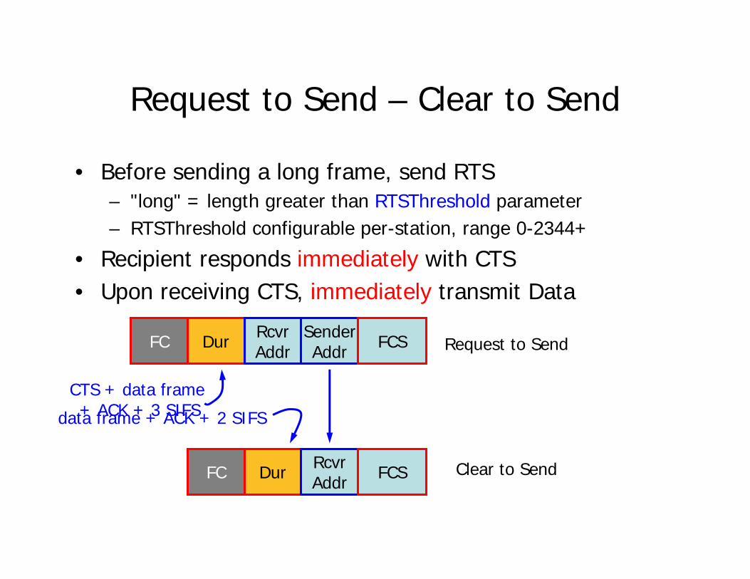
Request to Send – Clear to Send
• Before sending a long frame, send RTS– "long" = length greater than RTSThreshold parameter– RTSThreshold configurable per-station, range 0-2344+
• Recipient responds immediately with CTS• Upon receiving CTS, immediately transmit Data
FC Dur RcvrAddr
SenderAddr FCS Request to Send
FC Dur RcvrAddr FCS Clear to Send
CTS + data frame+ ACK + 3 SIFSdata frame + ACK + 2 SIFS
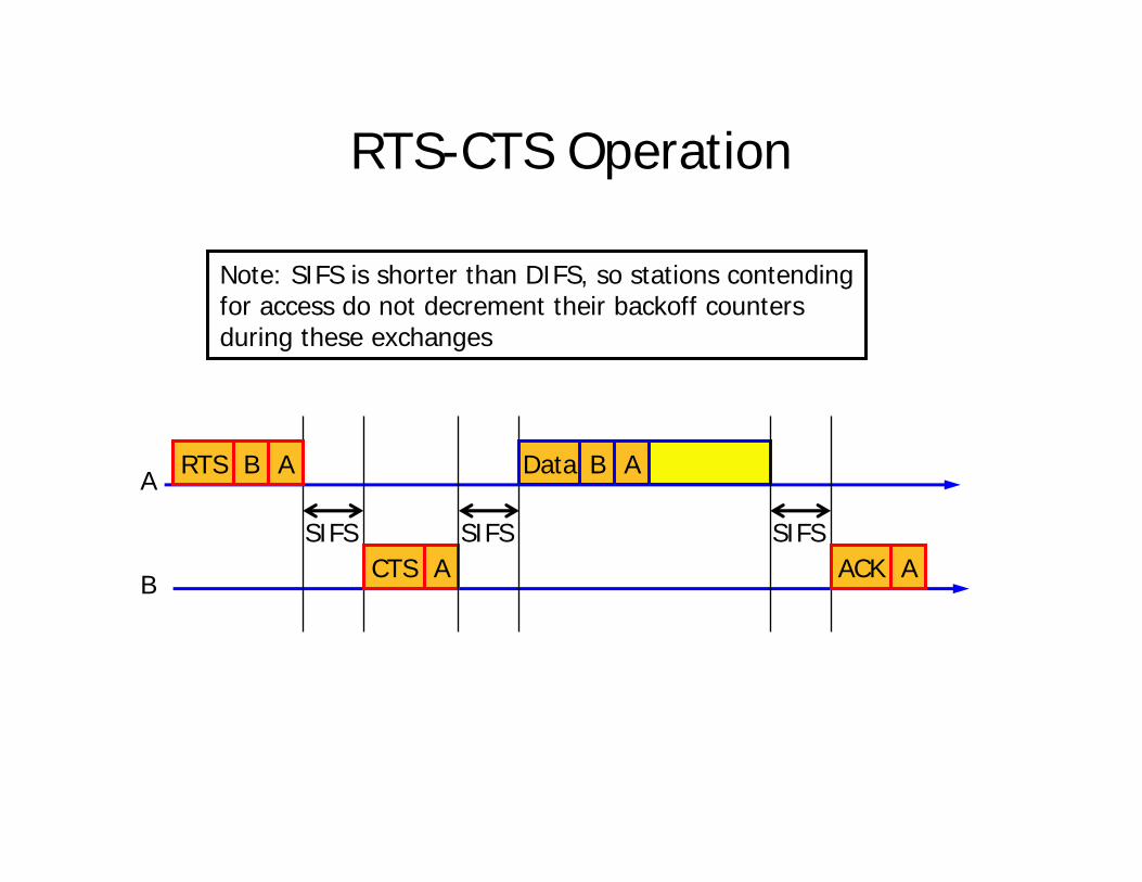
RTS-CTS Operation
A
B
RTS
SIFS
B A
CTS ASIFS
Data B A
SIFSACK A
Note: SIFS is shorter than DIFS, so stations contendingfor access do not decrement their backoff countersduring these exchanges

Network Allocation Vector (NAV)
• Each station maintains a countdown timer that tells how far into the future the medium has been "reserved" by RTS/CTS exchanges
• Stations set NAV counter based on the value in the duration field of frames– Even if a station only hears one side of the RTS-CTS
exchange, it knows how long the medium will be "busy"
• CCA function combines NAV and physical sensing– Medium considered busy if NAV value > 0

General Frame Format
FC Dur Addr1 Addr2 Addr3 SeqControl
Addr4 Payload FCS
2 2 6 6 6 2 6 0-2312 2 bytes
Duration of next frame, in microsecs (max 32,767)RTS: duration of CTS + data frame + ACK + 3 SIFSCTS: RTS duration – CTS – SIFSData w/ More Frags = 1: duration of next fragData w/ More Frags = 0: duration of ACK + SIFS

Fragment Bursts
RTS
SIFS
CTS ACK
F:0 XMF:1
SIFS SIFS SIFS
F:1 XMF:0
SIFSACK
Duration
Duration
Duration
Duration
Management: Who's Playing?
• MAC layer must provide stations a way to:– Learn what SS's are available– Associate with a particular SS (and authentication)– Disassociate from a SS
• Beacon Frames are broadcast periodically by the Access PointContains: SS ID, Access Point address (if any), Beacon frame
interval, supported data rates
• Stations may also send Probe frames to solicit information from APs (sent in Probe response msgs)
• Management frames are transmitted with higher priority– Implemented by using a smaller Priority Inter-frame Space
Point Coordination Function
• Idea: allow for explicit allocation of the channel– AP acts as Controller, polls stations– During a contention-free period, all stations see the
medium as busy (for purposes of contention)• Frame types:
– Beacon (indicates start, duration of contention-free period)
– CF-Poll, CF-Ack– Data+CF-Poll, Data+CF-Ack, Data+CF-Poll+CF-Ack
• When polled, station may transmit 1 (data) frame to any station

PCF Operation
• Special beacon marks beginning of CF period– Sent after sensing medium idle for PIFS (< DIFS)
• Prevents other stations from contending for medium
– Indicates duration of CF period• Non-PCF-capable stations set NAV to that value
PCBeacon*
PIFS
A
B
SIFS A:CFPoll
Data
SIFS
B A
ACKSIFS B: Data
+CF-Poll
SIFS
SIFS
Data+CF-AckC B