Embed Size (px)
Citation preview
LEVITON.COM/CROSSTALK 1
IN THIS ISSUE
UPCOMING EVENTS
Monitoring Networks with Passive Optical TAPs
Networking AV Systems for BYOD Collaboration
News You Can Use
Tech Tips
Ask The Experts
Standards Snapshot
MAY 8 - 11BICSI CanadaVancouver, BC
JUNE 25 - 29Cisco LiveLas Vegas, NV
Network visibility is a top priority for many IT managers. When networks become larger and more complex, monitoring for performance and security is no longer optional, it becomes critical. Industries such as financial, medical, and telecom markets need visibility tools to manage their networks and handle troubleshooting quickly and efficiently. And it needs to be done without adding any disruptions to the network.
That’s why more IT directors are using fiber optic TAPs to monitor network links.
Monitoring Networks with Passive Optical TAPsCreating Traffic Visibility without Disruption
continued on pg. 2
Networking AV Systems for BYOD Collaboration
LEVITON POLLLeviton recently asked those who install HDBaseT extension what cable type they used.
2015 2017Cat 5e 9% 5%
Cat 6 UTP 41% 24%
Cat 6 FTP (shielded) 20% 8%
Cat 6A UTP 15% 41%
Cat 6A FTP (shielded) 15% 21%
Switch
01000101100100100110110011001001
Switch
1001001001
10010
01001
MONITORING
TAP
One of the benefits of Leviton’s IT/AV solutions and control systems is their plug-and-play capabilities, as they can easily extend HD video signals to displays over HDBaseT technology. This means users who want to take advantage of Bring Your Own
Device (BYOD) collaboration in the workplace or classrooms can directly plug in their smartphones, tablets, or laptop to a display without any additional setup or hassle.
Occasionally we receive the question, “What if I want to use a sharing device like Apple TV for collaboration with BYOD?” There are a number of popular devices that enable easy wireless collaboration over smartphones, iPads or laptops. The most recognizable sharing devices include Google Chromecast, Amazon Fire TV, Apple TV, and Barco ClickShare.
These devices communicate over Wi-Fi, and connect to the display over HDMI. However, when using these solutions in the workplace or in classrooms, there is sometimes a concern that the devices allow for too much open or uncontrolled access, since anyone can connect and display whatever is on their device. Also, the streaming device and tablet, phone, or laptop need to be connected to the same WiFi network, which can be a secondary challenge. Other sharing devices geared for the enterprise such as Mersive Solstice offer extra collaboration tools, act as WiFi hotspots, and allow meeting moderators to control what is allowed on the display, but these come at a significantly higher cost and require additional IT setup and maintenance.
continued on pg. 4
The poll revealed a rise in installations using Cat 6A compared to the same poll in 2015.
2 31 4to SuccessfulDeployment
FOUR STEPS
Enterprise Wireless: 4 Steps to Successful Deployment
Webinar: Tuesday, April 25, 201710 am. (PT) / 1 pm. (ET)
Your Source for Industry News & Insight
CrossTalk NEWSLETTERVol. 8 | Mar/Apr 2017
LEVITON.COM/CROSSTALK 2
Monitoring Networks with Passive Optical TAPs • continued from pg. 1
What is a TAP?A traffic analysis point (TAP) is designed to allow traffic being sent over a fiber optic path to be monitored for security or network performance. The tap is positioned in the passive cabling system between a host and recipient device.
TAPs create greater visibility into a network. They provide a window into your data for security or surveillance. But they also make it possible to look at data packets and advise the network administrator on how the network is performing in real time.
Analyzing data in real time can be as simple as viewing a bank transaction or seeing if a health care record was placed in the correct file. And when there are millions of transactions happening constantly, TAPs will help find any bottlenecks in your network.
C1
R1
C2
R2
P1
P2TAP X
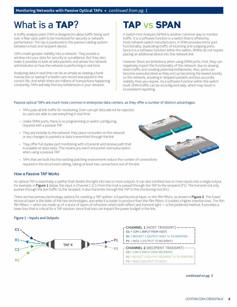
C1 = COM 1 (INPUT FROM HOST)
R1 = REFLECT 1 (OUTPUT HOST Tx TO MONITOR)
P1 = PASS 1 (OUTPUT TO RECIPIENT)
CHANNEL 1 (HOST TRANSMIT)
C2 = COM 2 (INPUT FROM RECIPIENT)
R2 = REFLECT 2 (OUTPUT RECIPIENT Tx TO MONITOR)
P2 = PASS 2 (OUTPUT TO HOST)
CHANNEL 2 (RECIPIENT TRANSMIT)
TAP vs SPANA Switch Port Analyzer (SPAN) is another common way to monitor traffic. It is a software function in a switch that is offered by most network switch manufacturers. A SPAN provides mirror port functionality, duplicating traffic of incoming and outgoing ports. Since it is a software function within the switch, SPANs do not require placing an additional device into the network link.
However, there are limitations when using SPAN ports. First, they can negatively impact the functionality of the network, due to slowing down traffic and creating potential bottlenecks. Also, ports can become oversubscribed so they end up becoming the lowest priority on the network, resulting in dropped packets and less accurate visibility than you require. As a software function within the switch itself, SPAN traffic can be reconfigured daily, which may result in inconsistent reporting.
Passive optical TAPs are much more common in enterprise data centers, as they offer a number of distinct advantages:
• TAPs pass all link traffic for monitoring. Even corrupt data will not be rejected, so users are able to see everything in real time.
• Unlike SPAN ports, there is no programming or switch configuring required with a passive TAP.
• They are invisible to the network: they place no burden on the network or any changes to packets or data transmitted through the link
• They offer full duplex port monitoring with a transmit and receive path that is scalable at data rates. This means you won’t encounter oversubscription when using a passive TAP.
• TAPs that are built into the existing patching environment reduce the number of connections required in the structured cabling, taking at least two connections out of the link.
How a Passive TAP Works
An optical TAP is essentially a splitter that divides the light into two or more outputs. It can also combine two or more inputs into a single output. For example, in Figure 1 below, the input in Channel 1 (C1) from the host is passed through the TAP to the recipient (P1). The transmit not only pushes through the live traffic to the recipient, it also transmits through the TAP to the monitoring tool (R1).
There are two primary technology options for creating a TAP splitter: a fused biconical taper, or thin film filters, as shown in Figure 2. The fused biconical taper is the older of the two technologies, and while it is easier to produce than thin film filters, it creates a higher insertion loss. The thin film filters — which are made up of a stack of layers of refraction which both reflect and transmit light — is the preferred method. It provides a lower loss that is critical for a TAP solution, since that loss can impact the power budget in the link.
Figure 1 – Inputs and Outputs
continued on pg. 3
LEVITON.COM/CROSSTALK 3
Monitoring Networks with Passive Optical TAPs • continued from pg. 2
The construction of a splitter makes the flow of data directionally specific. The monitoring outputs (reflect fibers) only receive traffic. In each TAP, one monitoring/reflect output receives transmitted traffic from the original host device and the other receives response transmission from the recipient device.
A TAP cassette has multiple tap splitters based on the number of designed outputs. Each signal (per TAP splitter) is split to “live” and “monitoring” output signals at a pre-determined ratio — typically 50/50 or 70/30 (70 live and 30 monitoring).
A 70/30 split ratio is generally the preferred method, as it dedicates a higher percentage for network traffic, avoiding any dropped packets. The 70/30 split is most commonly used in 1 Gb/s and 10 Gb/s networks. However, at higher speeds such as 40 Gb/s and 100 Gb/s, the 50/50 ratio is more commonly used in order to meet power budgets.
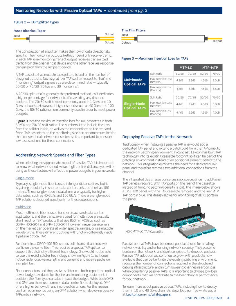
Figure 3 lists the maximum insertion loss for TAP cassettes in both 50/50 and 70/30 split ratios. The numbers listed include the loss from the splitter inside, as well as the connections on the rear and front. TAP cassettes on the monitoring side can become much lossier than conventional network cassettes, so it is important to consider low-loss solutions for these connections.
MTP-LC MTP-MTP
Multimode Optical TAPs
Split Ratio 50/50 70/30 50/50 70/30
Max Insertion Loss (Network) 4.3dB 2.3dB 4.3dB 2.3dB
Max Insertion Los (Monitor) 4.3dB 6.3dB 4.5dB 6.5dB
Single-Mode Optical TAPs
Split Ratio 50/50 70/30 50/50 70/30
Max Insertion Loss (Network) 4.4dB 2.9dB 4.6dB 3.0dB
Max Insertion Los (Monitor) 4.4dB 6.6dB 4.6dB 7.0dB
Input
OutputOutput
Input Output
Output
Fused Biconical Taper
Thin Film Filters
Figure 2 — TAP Splitter Types
Figure 3 — Maximum Insertion Loss for TAPs
Addressing Network Speeds and Fiber Types
When selecting the appropriate model of passive TAP, it is important to know what network speed, wavelength, or link distance you will be using as these factors will affect the power budgets in your network.
Single-mode
Typically, single-mode fiber is used in longer distance links, but it is gaining popularity in shorter data centers links, as short as 150 meters. These single-mode installations are typically for higher data rates, such as 40 Gb/s and 100 Gb/s. There are single-mode TAP solutions designed specifically for these applications.
Multimode
Most multimode fiber is used for short reach and data center applications, and the transceivers used for multimode are usually short reach or “SR” products that use 850 nm VCSELs, such as QSFP+ 40G-SR4 and SFP+ 10G-SR4. However, newer transceivers on the market can operate at wider spectral ranges, or use multiple wavelengths. These different options will function differently inside a passive optical TAP.
For example, a CISCO 40G BIDI carries both transmit and receive traffic on the same fiber. This requires a special TAP splitter to support this distinctly different technology. One would not be able to use the exact splitter technology shown in Figure 1, as it does not consider dual wavelengths and transmit and receive paths on a single fiber.
Fiber connectors and the passive splitter can both impact the optical power budget available for the link and monitoring equipment. In addition, the fiber type can also impact the budget. While both OM3 and OM4 are the most common data center fibers deployed, OM4 offers higher bandwidth and improved distances. For this reason, Leviton recommends using an OM4 solution when deploying passive TAPs into a network.
Deploying Passive TAPs in the Network
Traditionally, when installing a passive TAP, one would add a dedicated TAP panel and extend a patch cord from the TAP panel to the network patching environment. In contrast, Leviton has built TAP technology into its existing cassette footprint so it can be part of the patching environment instead of an additional element added to the network. This integration eliminates the need for a dedicated TAP panel and therefore removes two additional connections from the channel.
The integrated design also conserves rack space, since no additional TAP panel is required. With TAP ports on the rear of the cassette instead of front, no patching density is lost. The image below shows a 1RU HDX panel, with the TAP cassette removed and the rear MTP TAP port in blue. This design allows for monitoring of all 72 ports in the panel.
Passive optical TAPs have become a popular choice for creating network visibility and enhancing network security. They place no burden on the network, and don’t contribute to dropped packets. Passive TAP adoption will continue to grow, with products now available that can be built into the existing patching environment, reducing the number of connections required in the structured cabling infrastructure, and in turn lowering channel insertion loss. When considering passive TAPs, it is important to choose low-loss components that will contribute to the best channel performance for your network.
To learn more about passive optical TAPs, including how to deploy them in 10 and 40 Gb/s channels, download our free white paper at Leviton.com/ns/whitepapers.
HDX MTP-LC TAP Cassette
Input
OutputOutput
Input Output
Output
Fused Biconical Taper
Thin Film Filters
LEVITON.COM/CROSSTALK 4
Networking AV Systems for BYOD Collaboration • continued from pg. 1
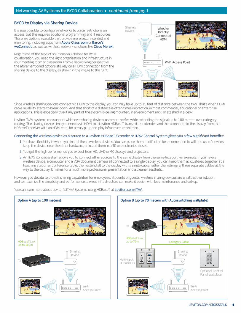
BYOD to Display via Sharing DeviceWIred or Directly
ConnectedHDMI
SharingDevice
Wi-Fi Access Point
It is also possible to configure networks to place restrictions on access, but this requires additional programming and IT resources. There are options available that provide more secure control and monitoring, including apps from Apple Classroom or Barco’s weConnect, as well as wireless network solutions like Cisco Meraki.
Regardless of the type of solutions you choose for BYOD collaboration, you need the right organization and infrastructure in your meeting room or classroom. From a networking perspective the aforementioned options still rely on a HDMI connection from the sharing device to the display, as shown in the image to the right.
Since wireless sharing devices connect via HDMI to the display, you can only have up to 15 feet of distance between the two. That’s when HDMI cable reliability starts to break down. And that short of a distance is often times impractical in most commercial, educational or enterprise applications. This is especially true if any part of the system is ceiling mounted, in an equipment rack, or stashed in a desk.
Leviton IT/AV systems can support whichever sharing device customers prefer, while extending the signal up to 100 meters over category cabling. The sharing device simply connects via HDMI to a Leviton HDBaseT transmitter extender, and then connects to the display from the HDBaseT receiver with an HDMI cord, for a truly plug-and-play infrastructure solution. Connecting the wireless device as a source to a Leviton HDBaseT Extender or IT/AV Control System gives you a few significant benefits:
1. You have flexibility in where you install these wireless devices. You can place them to offer the best connection to wifi and users’ devices, keep the device near the other hardware, or install them in a TR or electronics closet.
2. You get the high performance you expect from HD, UHD or 4K displays and projectors.
3. An IT/AV control system allows you to connect other sources to the same display from the same location. For example, if you have a wireless device, a computer and a VGA document camera all connected to a single display, you can keep them all clustered together at a teaching station or conference table, then extend all to the display with a single cable, rather than stringing three separate cables all the way to the display. It makes for a much more professional presentation and a cleaner aesthetic.
However you decide to provide sharing capabilities for employees, students or guests, wireless sharing devices are an attractive solution, and to maximize the simplicity and performance, a wired infrastructure can make it easier, with less maintenance and set-up.
You can learn more about Leviton’s IT/AV Systems using HDBaseT at Leviton.com/ITAV.
Option A (up to 100 meters) Option B (up to 70 meters with Autoswitching wallplate)
Wi-Fi Access Point
Rx
Tx
HDBaseT Linkup to 100m
Rx
Multi-InputHDBaseT Tx
HDBaseT Linkup to 70m
SharingDevice
SharingDevice
Optional Control Panel Wallplate
Wi-Fi Access Point
Category Cable
LEVITON.COM/CROSSTALK 5
NEWS USEYOUCAN
YESTERDAY’S NEWS1857: 160 years ago, Heinrich Hertz was born. He was the first to prove the existence of electromagnetic waves. Also, the unit of frequency Hertz (Hz) takes his name, where 1 Hz is defined as 1 cycle per second.
INDUSTRYSales of 100 GbE optical transceivers reached $1.15 billion in 2016, up 150% from 2015, according to market research firm LightCounting. The sales ramped strongly in the second half of 2016, and sales are expected to remain strong in 2017.
On February 28, Amazon Web Services (AWS) experienced a major outage to its Simple Storage Service (S3). The outage took down a portion of the web for several hours. The reason, according to Amazon, was due to human error, as a command to remove a small group of servers entered incorrectly and a larger set of servers was removed. It took several hours to restart these systems and complete safety checks.
Terminating Ribbonized MTP Pigtails
5
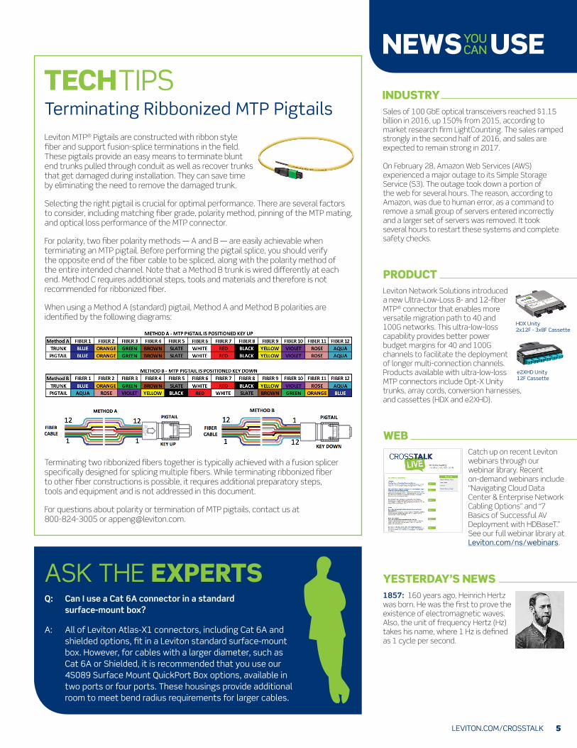
Leviton MTP® Pigtails are constructed with ribbon style fiber and support fusion-splice terminations in the field. These pigtails provide an easy means to terminate blunt end trunks pulled through conduit as well as recover trunks that get damaged during installation. They can save time by eliminating the need to remove the damaged trunk.
Selecting the right pigtail is crucial for optimal performance. There are several factors to consider, including matching fiber grade, polarity method, pinning of the MTP mating, and optical loss performance of the MTP connector.
For polarity, two fiber polarity methods — A and B — are easily achievable when terminating an MTP pigtail. Before performing the pigtail splice, you should verify the opposite end of the fiber cable to be spliced, along with the polarity method of the entire intended channel. Note that a Method B trunk is wired differently at each end. Method C requires additional steps, tools and materials and therefore is not recommended for ribbonized fiber.
When using a Method A (standard) pigtail, Method A and Method B polarities are identified by the following diagrams:
PRODUCTLeviton Network Solutions introduced a new Ultra-Low-Loss 8- and 12-fiber MTP® connector that enables more versatile migration path to 40 and 100G networks. This ultra-low-loss capability provides better power budget margins for 40 and 100G channels to facilitate the deployment of longer multi-connection channels. Products available with ultra-low-loss MTP connectors include Opt-X Unity trunks, array cords, conversion harnesses, and cassettes (HDX and e2XHD).
WEBCatch up on recent Leviton webinars through our webinar library. Recent on-demand webinars include “Navigating Cloud Data Center & Enterprise Network Cabling Options” and “7 Basics of Successful AV Deployment with HDBaseT.” See our full webinar library at Leviton.com/ns/webinars.
ASK THE EXPERTSQ: Can I use a Cat 6A connector in a standard
surface-mount box?
A: All of Leviton Atlas-X1 connectors, including Cat 6A and shielded options, fit in a Leviton standard surface-mount box. However, for cables with a larger diameter, such as Cat 6A or Shielded, it is recommended that you use our 4S089 Surface Mount QuickPort Box options, available in two ports or four ports. These housings provide additional room to meet bend radius requirements for larger cables.
Terminating two ribbonized fibers together is typically achieved with a fusion splicer specifically designed for splicing multiple fibers. While terminating ribbonized fiber to other fiber constructions is possible, it requires additional preparatory steps, tools and equipment and is not addressed in this document.
For questions about polarity or termination of MTP pigtails, contact us at 800-824-3005 or [email protected].
HDX Unity2x12F - 3x8F Cassette
e2XHD Unity 12F Cassette

6
STANDARDS SNAPSHOTKeeping you up to date on important developments from IEEE, TIA, and BICSI.
TIATIA TSB-184-A “Guidelines for Supporting Power Delivery Over Balanced Twisted-Pair Cabling” has been approved for publication. The guidelines were created in cooperation with the IEEE 802.3bt draft standard specifying four-pair POE.
TIA TSB-5021 “Guidelines for the Assessment and Mitigation of Installed Cabling to Support 2.5GBASE-T and 5GBASET” has been published. The standard specifies using installed Category 5e and 6 to support 2.5 and 5 GbE networks.
Requirements for Category 8 and OM5 fiber are being implemented in many of the application specific ANSI/TIA standards, including: 568.0-D (generic), 568.1-D (commercial), 862-B (intelligent buildings), 4966 (education), 1179-A (healthcare), and 942-B (data centers).
ANSI/TIA-942-B “Telecommunications Infrastructure Standard for Data Centers” has moved to the first Default Ballot, and will publish if no further technical or “no” votes are received. The updated standard will also address the new Category 8 and OM5 media types.
IEEEThe IEEE 802.3bs draft defining 200 Gb/s and 400 Gb/s over optical fiber was edited and moved to draft 3.1 for sponsor ballot. The target date for publication is December 2017.
The IEEE 802.3cd draft for 50 Gb/s Ethernet over a single lane has moved to draft 1.3. It sets maximum distances of 70 meters over OM3, and 100 meters over OM4 and OM5. The standard also included specifications for 100 Gb/s and 200 Gb/s over multiple 50 Gb/s lanes. The target date for publication is September 2018.
ISO/IECISO is nearing the end of a major revision to the 11801 cabling standards. It has progressed to Final Draft International Standard (FDIS), which is the last stage before publication. Publication is expected in October or November 2017. The new revision, Edition 3, will be organized into six parts:
TITLE ISO/IEC STANDARD REPLACES
Part 1: General requirements ISO/IEC 11801-1 ISO/IEC 11801
Part 2: Office premises ISO/IEC 11801-2 ISO/IEC 11801
Part 3: Industrial premises ISO/IEC 11801-3 ISO/IEC 24702
Part 4: Homes ISO/IEC 11801-4 ISO/IEC 15018
Part 5: Data centers ISO/IEC 11801-5 ISO/IEC 24764
Part 6: Distributed building services ISO/IEC 11801-6 ISO/IEC TR 24704
BICSIBICSI has published the Information Technology Systems Installation Methods Manual (ITSIMM), 7th edition. The updated ITSIMM includes “recent trends and advancements within ICT cabling and applications, such as Category 8/Class I/II cabling, adoption of data center/mission-critical facility methods within common installations, and the increasing commonality of support required by systems that sustain building functions.”
Email: [email protected]
QUESTIONS? COMMENTS? IDEAS?We want to hear from you!
Have a question? Would you like to subscribe or unsubscribe to CrossTalk? Drop us a line at [email protected].
© 2017 Leviton Manufacturing Co., Inc.