Embed Size (px)
Citation preview

1
IntegratedClassroomControl SystemInstallation and Operation Manual
WE
B V
ER
SIO
N
2
TABLE OF CONTENTS
Introduction . . . . . . . . . . . . . . . . . . . . . . . . . . . . . . . . . . . . . . . . . . . . . . . . . . . . . . . . . . . . . . . . . . . . . . . . . . . . . . . . .3
Installation . . . . . . . . . . . . . . . . . . . . . . . . . . . . . . . . . . . . . . . . . . . . . . . . . . . . . . . . . . . . . . . . . . . . . . . . . . . . . . . . . .4
Operation . . . . . . . . . . . . . . . . . . . . . . . . . . . . . . . . . . . . . . . . . . . . . . . . . . . . . . . . . . . . . . . . . . . . . . . . . . . . . . . . . . .8
Notes: Daylighting Configuration . . . . . . . . . . . . . . . . . . . . . . . . . . . . . . . . . . . . . . . . . . . . . . . . . . . . . . . . . . . 14
Appendix A Open Loop Calculation – Cheat Sheet. . . . . . . . . . . . . . . . . . . . . . . . . . . . . . . . . . . . . . . . . . . 15
Appendix B Classroom System Layout. . . . . . . . . . . . . . . . . . . . . . . . . . . . . . . . . . . . . . . . . . . . . . . . . . . . . . 16
Specifications and Ordering Information . . . . . . . . . . . . . . . . . . . . . . . . . . . . . . . . . . . . . . . . . . . . . . . . . . . . 17
Warranty . . . . . . . . . . . . . . . . . . . . . . . . . . . . . . . . . . . . . . . . . . . . . . . . . . . . . . . . . . . . . . . . . . . . . . . . . . . . . . . . . . 19
WE
B V
ER
SIO
N

3
INTRODUCTION
Many classrooms use mediocre lighting quality and high energy costs. Most high efficiency systems require a piecemeal approach when including automatic controls for occupancy and dimming. Specifying individual control components greatly increases design time and cost. Each component carries an individual warranty, causing confusion and potential delayed repair time if performance problems occur.
Leviton’s Integrated Classroom Control System is a packaged solution that meets the daylighting control methods being adopted across the United States. Our advanced system offers intuitive and user friendly control stations with daylight harvesting, occupancy sensing and energy management capabilities.
Leviton’s Integrated Classroom Control System package is a benefit in many classroom scenarios and will save you installation time and labor to implement.
Our trouble-free plug and play products will save you installation time by running category 5 wiring between the System Control Module, Teacher Control Station (TCS), and Row Controller. An additional time saver is the AutoCalTM automatic calibration feature. It will streamline the daylight harvesting setup. Simply turn on the AutoCalTM feature and walk away.
The facility will experience energy savings associated with an improved smart lighting control system while creating a classroom environment fit for better learning and comprehension.
System Kit Components1. System Control Module
2. Teacher Control Stationa. White Board b. Quiet-Timec. Audio Visual / General Lighting Controls ON/OFFd. Audio Visual / General Lighting Controls Dimming (0-10V)
3. 50 ft. Cat5 cables (2 cables provided with purchase of kits that include Row Control Panels)
4. Row Control Station (optional)
5. (1) Multiple Technology Occupancy Sensor (optional)
6. (1) Photocell Sensor (optional)
WE
B V
ER
SIO
N

4
INSTALLATION
System Control Module
WARNING AND CAUTION
a. Shall operate in an ambient temperature range of 0 thru 40 degrees C (32 thru 104F)
b. Shall operate in 5% thru 95% humidity, non condensing
c. For indoor use only
Suggest mounting within 50ft. of control stations.
Mounting holes are provided in the module. The upper holes are keyhole slots to facilitate easy hanging. Any field drilled mounting holes should be confined to the wire-way areas. See Illustration A.
Please make sure all mounting and drilling debris is completely removed from the unit before applying power.
Five (5) concentric knockout holes are provided on all sides in both the low-voltage and high-voltage compartments.
1. Securely mount module to wall using fasteners appropriate for wall type.
2. Install all control runs and pull all lighting circuits, power wiring, and low voltage wiring.
CONCENTRIC KNOCKOUTS TO ACCOMMODATE
3/4” & 1” CONDUIT (1.109” - 1.375”)
5 PLACES
4.00[101.60]
18.00 [457.20]
16.00 [406.40]
16
.00
[40
6.4
0]
14
.00
[35
5.6
0]
WE
B V
ER
SIO
N
5
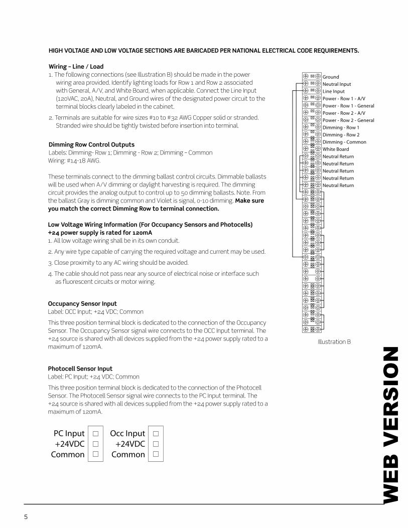
1. The following connections (see Illustration B) should be made in the power wiring area provided. Identify lighting loads for Row 1 and Row 2 associated with General, A/V, and White Board, when applicable. Connect the Line Input (120VAC, 20A), Neutral, and Ground wires of the designated power circuit to the terminal blocks clearly labeled in the cabinet.
2. Terminals are suitable for wire sizes #10 to #32 AWG Copper solid or stranded. Stranded wire should be tightly twisted before insertion into terminal.
Dimming Row Control OutputsLabels: Dimming- Row 1; Dimming - Row 2; Dimming – CommonWiring: #14-18 AWG.
These terminals connect to the dimming ballast control circuits. Dimmable ballasts will be used when A/V dimming or daylight harvesting is required. The dimming circuit provides the analog output to control up to 50 dimming ballasts. Note. From the ballast Gray is dimming common and Violet is signal, 0-10 dimming.
1. All low voltage wiring shall be in its own conduit.
2. Any wire type capable of carrying the required voltage and current may be used.
3. Close proximity to any AC wiring should be avoided.
4. The cable should not pass near any source of electrical noise or interface such as fluorescent circuits or motor wiring.
Label: OCC Input; +24 VDC; Common
This three position terminal block is dedicated to the connection of the Occupancy Sensor. The Occupancy Sensor signal wire connects to the OCC Input terminal. The +24 source is shared with all devices supplied from the +24 power supply rated to a maximum of 120mA.
Label: PC Input; +24 VDC; Common
This three position terminal block is dedicated to the connection of the Photocell Sensor. The Photocell Sensor signal wire connects to the PC Input terminal. The +24 source is shared with all devices supplied from the +24 power supply rated to a maximum of 120mA.
Dimming - Row 1Dimming - Row 2Dimming - Common
Line InputNeutral InputGround
Power - Row 1 - A/VPower - Row 1 - GeneralPower - Row 2 - A/V Power - Row 2 - General
White Board
Neutral ReturnNeutral ReturnNeutral Return
Neutral ReturnNeutral Return
��
��
��
��
���
����
����
����
����
����
����
����
����
����
����
����
����
����
Illustration B
PC Input+24VDC
Common
Occ Input+24VDC
Common
WE
B V
ER
SIO
N

6
Step 1. Mount back box - (3-1/2” deep back box suggested)Step 2. Securely mount the station to the back box using the provided screws*Step 3. Snap the wall plate onto the station
Step 4
Station must be flush mounted to the wall.W
EB
VE
RS
ION

7
CAT5 or better cable and RJ45 connectors connect teacher control stations and row control stations to the input board located inside the control enclosure.
���������������������������
������
���������
���������
Classroom Control Module
Add-A-Relay(OSA20-R00)
Power Pack(OSP20-0D0)
Power Pack(OSP20-0D0)
Power Pack(OSP20-0D0)
Add-A-Relay(OSA20-R00)
Dim
min
g - R
ow 1
Dim
min
g - R
ow 2
Dim
min
g - C
omm
on
Line
Inpu
tNe
utra
l Inp
utG
roun
d
Powe
r - R
ow 1
- A/
VPo
wer -
Row
1 -
Gen
eral
Powe
r - R
ow 2
- A/
VPo
wer -
Row
2 -
Gen
eral
Whi
te B
oard
Neut
ral R
etur
nNe
utra
l Ret
urn
Neut
ral R
etur
n
Neut
ral R
etur
nNe
utra
l Ret
urn
miniZ(MZD22-102)
Teacher Station
RowSwitching
CommonWhite Board PP Control
Occupancy Sensor
Photocell Sensor
1 2 3 4 5 6 7 8 9 10 11 12 13 14 15 16 17 18 19 20 21 22 23 24 25 26 27 28 29
1 19
30 31 32 33 34 35
27 8 9 10 28 29 11 30 31 20 4 5 6 723 24 2521 2232 33
36
34 35 36
Teacher Station
RowSwitching
Category 5 or better wireTypical of all runs with RJ45 interconnections
WHITEBOARD
A/V MODEDIMMING
QUITE TIME1 HOUR ON
GENERAL
Teachers Control Station(TCS0Q-WAD)
ROW1
ROW2
Row Control Station(TE000-RCS)
WE
B V
ER
SIO
N

8
OPERATION
The Teacher Control Station (TCS) is usually located near the primary teaching position and is the main lighting control for the room. It contains various switches which have different functions for customizing the lighting.
The switch labeled “GENERAL MODE” and “A/V MODE” is responsible for controlling the lamps in your lighting fixtures.
The outer two lamps are referred to as general lighting and are usually up lights; they reflect off ceiling and walls. The inner lamp is used as A/V lighting and is cast straight down. Our system controls two rows of these lamp and ballast combinations.
The teacher may select General Mode or A/V Mode, but these cannot remain on at the same time.
Teacher Control Station (TCS)
Since the analog 0-10V control signals switch each row instead of each mode, there is potentially a 2-3 second period of darkness whenever there is a change between modes. This is because of the various delays in lamp strikes. To alleviate this concern, Leviton has implemented the following feature into its classroom systems:
1) When switching from General mode to A/V mode, Leviton classroom systems continue to hold the General lamps ON for 3 seconds after turning ON the A/V lamps to fill the gap.
2) When switching from A/V mode to General mode, Leviton classroom systems continue to hold the A/V lamps ON for 3 seconds after turning ON the General lamps to fill the gap.
WE
B V
ER
SIO
N

9
The Row Control Station provides manual control of both rows of lights. It is considered the master power switch for each row.
The Occupancy Sensor connects to the system control enclosure through low voltage wiring. Leviton includes one Multi technology occupancy sensor as part of your systems kit.
Multi technology means that both PIR and Ultrasonic sensor technologies are built into a single sensor. PIR and/or Ultrasonic technology detects occupancy. Once on, detection by either sensor technology will keep the lights on.
Please reference the installation instructions that come with your occupancy sensor.
Photocell Sensors or Daylight Control sensors should be ceiling mounted facing the primary window wall located approximately halfway between the first row of fixtures and the wall. When sufficient daylight is present light fixutres will begin to dim to minimum depending on how the system has been wired and configured. Leviton includes one photocell sensor as part of your systems kit.
Please reference the installation instructions that come with your photocell sensor.
Row Control Station
A/V Mode Dimming/General Mode – Switch
The A/V Dimming and General Mode switch has two functions:
When in A/V Dimming Mode, the instructor will use the slider to dim the center downlight of each fixture. When the button is pressed, the green LED will illuminate indicating the station is now in General Mode.
The teacher will use this momentary switch to temporarily override the motion sensor.
When the switch is pressed, the lighting in the classroom will stay on even in the absence of motion, for one hour. After one hour, the lighting will automatically restore to the occupancy sensed state. The instructor can toggle the switch at any time to re-set “Quiet-Time” to a full 60 minute override period. While in “Quiet Time” mode, the instructor will have full control of the classroom lighting.
WE
B V
ER
SIO
N
10
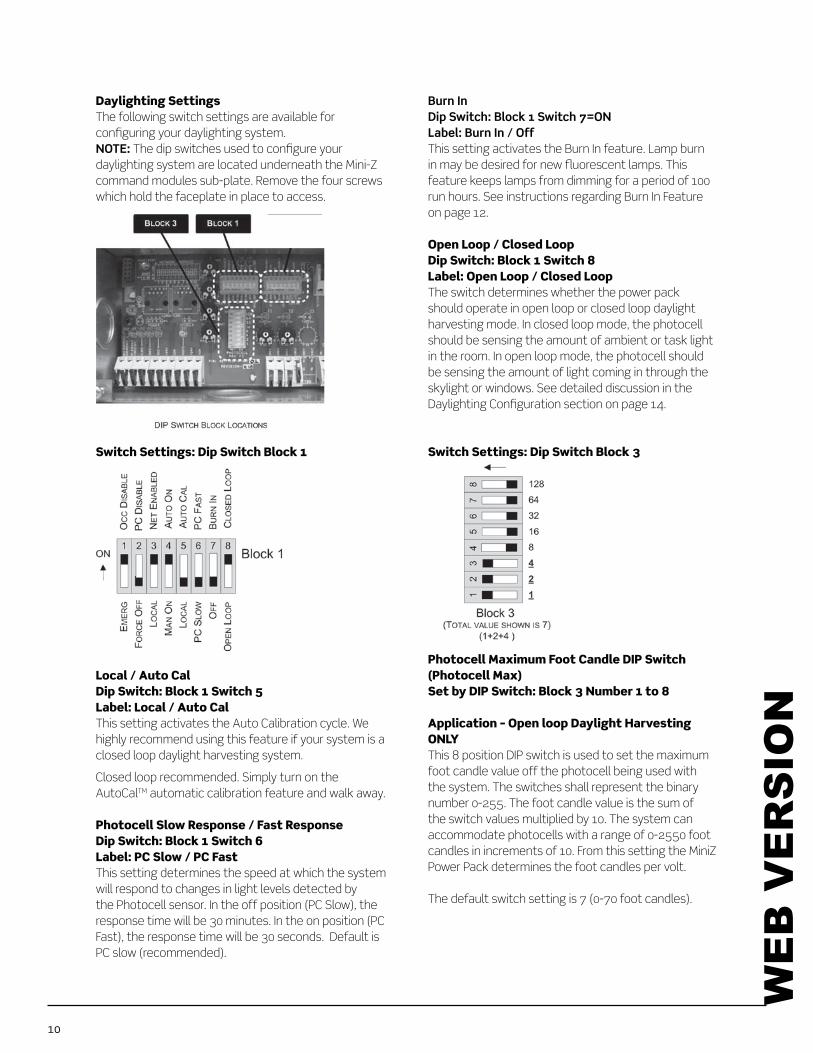
Daylighting SettingsThe following switch settings are available for configuring your daylighting system.
The dip switches used to configure your
command modules sub-plate. Remove the four screws which hold the faceplate in place to access.
Switch Settings: Dip Switch Block 1
Local / Auto CalDip Switch: Block 1 Switch 5Label: Local / Auto CalThis setting activates the Auto Calibration cycle. We highly recommend using this feature if your system is a closed loop daylight harvesting system.
Closed loop recommended. Simply turn on the AutoCalTM automatic calibration feature and walk away.
Photocell Slow Response / Fast ResponseDip Switch: Block 1 Switch 6Label: PC Slow / PC FastThis setting determines the speed at which the system will respond to changes in light levels detected by the Photocell sensor. In the off position (PC Slow), the response time will be 30 minutes. In the on position (PC Fast), the response time will be 30 seconds. Default is PC slow (recommended).
This setting activates the Burn In feature. Lamp burn in may be desired for new fluorescent lamps. This feature keeps lamps from dimming for a period of 100 run hours. See instructions regarding Burn In Feature on page 12.
Open Loop / Closed LoopDip Switch: Block 1 Switch 8Label: Open Loop / Closed LoopThe switch determines whether the power pack should operate in open loop or closed loop daylight harvesting mode. In closed loop mode, the photocell should be sensing the amount of ambient or task light in the room. In open loop mode, the photocell should be sensing the amount of light coming in through the skylight or windows. See detailed discussion in the Daylighting Configuration section on page 14.
Switch Settings: Dip Switch Block 3
Photocell Maximum Foot Candle DIP Switch (Photocell Max)Set by DIP Switch: Block 3 Number 1 to 8
Application – Open loop Daylight Harvesting ONLYThis 8 position DIP switch is used to set the maximum foot candle value off the photocell being used with the system. The switches shall represent the binary number 0-255. The foot candle value is the sum of the switch values multiplied by 10. The system can accommodate photocells with a range of 0-2550 foot
Power Pack determines the foot candles per volt.
The default switch setting is 7 (0-70 foot candles).
WE
B V
ER
SIO
N

11
Configuration Trim Pot Settings
Maximum Trim Pot (Max)Adjust this trim pot to set the upper limit for each 0-10 VDC Ballast outputs. The full range of the pot adjusts the upper limit in a range from 6 volts to 10 volts.
Default: Default position is full on (counter clockwise).
Minimum Trim Pot (Min)Adjust this trim pot to set the minimum dimming level for both 0-10 VDC Ballasts outputs during daylight harvesting mode operation. The full range of the pot adjusts the lower limit in a range from 1 to 4 volts.
Default: This default position is full off (clockwise).
Daylight Harvesting Offset Trim Pot (Offset)Dimming, Open LoopIn Open Loop mode, the Offset trim pot is used to enter the desired foot candle value from 0-100 foot candles, at the photocell. A setting of 0 equals 0 foot candles, a setting of 10 equals 100 foot candles.
Daylight Harvesting Offset Trim Pot (Offset)Dimming, Closed LoopIn Closed Loop mode, the Offset trim is used to set the target photocell values. The trim pots scale of 0-10 represents the 0-10 volt signal of the photocell. If, however, you are using Auto Calibration, the Offset trim pots define the Light Loss Factor (LLF) applied to the target level. The LLF is 20% when the trim pot is set at 0 and 0% when the trim pot is at 10. The assumption is that auto calibration occurs when the lamps are new, the fixtures are clean, and the room us performing to the initial lumen output not the maintained lumen output. When the Offset trim pot is set to 0, the LLF is set to 20%. When the trim pot is set to 10, the LLF is 0%.
Daylight Harvesting Threshold Trim Pot (Thresh)Our dimmed models, these trim pots will be used to determine the amount of daylight control that is applied to each zone. The full range of rotation represents 0-100% of the photocell’s foot candle range. The procedure for adjusting these trim pots is
set to operate as an open – or closed-looped system. In open loop, if daylight harvesting is not desired turning the pots full (100%) shall disable the feature and the lights on the zone will stay on at the Max level.
In closed loop, the Threshold trim pot has the added functionality that is can be used to exclude a zone from dimming, as it relates to daylight harvesting operation, by setting it to a value of less than 5%.
Default: The default position is full on (clockwise).
WE
B V
ER
SIO
N

12
Burn In FeatureSet by DIP switch: Block 1 Number 7=ON
Burn In feature will maintain the fluorescent fixtures at full illumination level for 100 hours. At the conclusion of the Burn IN
When to use itSome manufactures of fluorescent lamps require the lamps to be run at the full illumination level for a specific period prior to any dimming activity. This feature provides an easy method to satisfy that requirement.
StartTo initialize this function, move the DIP switch labeled Burn In to the ‘ON’ position. Observe: The LED above the DIP switch will glow red and will remain in that state until the cycle is complete. The fluorescent fixtures will also be illuminated at the full level when turned on until all zones have been on for 100 hours.
StopThe cycle can be stopped at any time by turning off the DIP switch. Observe: The red LED above the DIP switch will turn off.
RestartTo restart this function, move the DIP switch labeled Burn In to the ‘OFF’ and then ‘ON’ position for re-start. Observe: The observation will be the same as the Start step.
WE
B V
ER
SIO
N

13
Auto Calibration (Closed Loop Operation Only)Set the DIP switch: Block 1 Number 5= ON
The Auto Calibration During the 24 hour calibration period all fluorescent fixtures will remain at full illumination levels and cannot be turned off.calibration period. This reading typically occurs at night. At the conclusion of the Auto Calibration power Pack will enter normal operation.
Note: Auto Calibration is only applicable to closed loop photocell operation. When the device is config-ured in open loop mode, auto calibration can be activated but the results of such will have no effect on the configuration or output of the miniZ.
Start: To initiate this function, move the DIP switch labeled Auto Cal to the ‘ON’ position. Observe: The LED above the DIP switch will begin to flash on and off in a steady pattern until the calibration period is complete. The fluorescent fixture will also be illuminated at their full level for the duration of the cycle.
Stop: The cycle can be stopped at any time by turning off the DIP switch.Observe: The LED above the DIP switch will turn off.
Restart: To restart this function, move the DIP switch labeled Auto Cal to the ‘OFF’ position and then back to the ‘ON’ position.
End of Cycle: Observe:enter normal operation.
Note: Burn In and Auto Cal feature can occur at the same time.
WE
B V
ER
SIO
N

14
NOTES: DAYLIGHTING CONFIGURATION
SetupTo set up your system in either open loop or closed loop mode, please reference the DIP switch settings found on page 10.
Open-Loop OperationTypical open-loop systems employ a photocell positioned towards the daylight source (window skylight, etc).
IMPORTANT! For best results, the photocell should receive as little electric light as possible.
To determine the setting of each of the threshold time pots, light meter readings must be taken during the day with the electric lights off and during consistent daylight (i.e. if a cloud covers the sun during meter recording, start over or wait for the cloud to pass). Position the light meter at the photocell, pointing it in the same direction as the photocell. Record the value. Next position the light meter at the work surface of each zone pointing it towards the ceiling. Record the value at each zone.
Now calculate the ratio of the zone value to the photocell value at each zone. Use the chart below to determine the trim setting. For example, if the photocell reading is 400 foot candles and zone 1’s reading is 50 foot candles, the ratio is 50/400 = 0.125. Find 0.125 on the chart’s x-axis (Room/Photocell Ratio) and follow a straight line up until the diagonal line it intersected. Then follow a straight line to the left on the chart to obtain the trim pot setting. In this case the setting would be 0.7. See Appendix A Open Loop Cheat Sheet Set Up Procedure on page 15.
Closed-Loop Operation (Manual Configuration)Closed-loop systems position the photocell so that it measures the amount of light in the zone being controlled. It is possible to control multiple zones differently using a single photocell through the use of the threshold trim pots. It is important to correctly position the photocell so that it receives either the average amount of ambient light or if sensing task lighting that it is directed at a surface which will reflect an appropriate representation of the amount of task lighting in the room.
1. Enter the desired voltage or foot-candle for the photocell
2. Assuming the zone closest to the window is set to 100% (Trim pot 1 set to 10) set the other zones per the ratio of light that reaches them.
Note: AutoCal™ feature for closed loop systems is the recommended set up option for this product.
WE
B V
ER
SIO
N
15
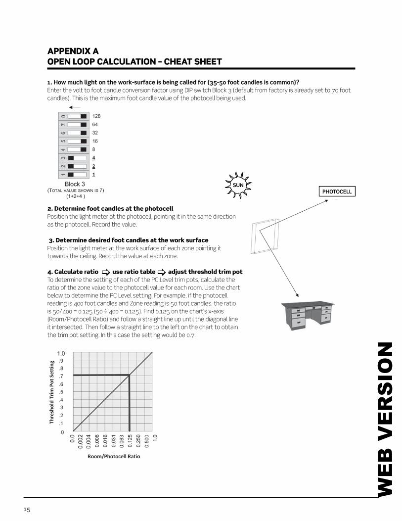
APPENDIX AOPEN LOOP CALCULATION – CHEAT SHEET
Enter the volt to foot candle conversion factor using DIP switch Block 3 (default from factory is already set to 70 foot candles). This is the maximum foot candle value of the photocell being used.
2. Determine foot candles at the photocellPosition the light meter at the photocell, pointing it in the same direction as the photocell. Record the value.
3. Determine desired foot candles at the work surfacePosition the light meter at the work surface of each zone pointing it towards the ceiling. Record the value at each zone.
4. Calculate ratio use ratio table adjust threshold trim potTo determine the setting of each of the PC Level trim pots, calculate the ratio of the zone value to the photocell value for each room. Use the chart below to determine the PC Level setting. For example, if the photocell
is 50/400 = 0.125 (50 ÷ 400 = 0.125). Find 0.125 on the chart’s x-axis (Room/Photocell Ratio) and follow a straight line up until the diagonal line it intersected. Then follow a straight line to the left on the chart to obtain the trim pot setting. In this case the setting would be 0.7.
SUN
WE
B V
ER
SIO
N

16
APPENDIX BCLASSROOM SYSTEM LAYOUT
Suggestion: 1. Row 1 should be connected to the luminaries closest to the day lit area such as the windows or skylights. This is
generally accepted to be approximately 12’ to 15’ from the daylight source.
2. Row 2 should be connected to the luminaries in the next area beyond 15’ to approximately 25’ from the daylight source.
Row 1
A/V ModeGeneral
A/V ModeGeneral
Row 2
CAT 5
Row 1
A/V ModeGeneral
Row 2
CAT 5
A/V ModeGeneral
CAT 5
Teachers Control Station (AV/ General and Quiet Time switches), Multi-Technology occupancy sensor and Classroom System Control Module.
Teachers Control Station (AV Dimming/ General, Quiet Time and Whiteboard switches), Row Control Station, Multi-Technology occupancy sensor and Classroom System Control Module.
WE
B V
ER
SIO
N

17
SPECIFICATIONS(1) 20A, 120 or 277V circuit feed
2 - For up to 50 Ballast each
+24VDC @120mA
ORDERING INFORMATION*CAT. NO. DESCRIPTION
CCE0Q-000 Classroom System Control Module, White
CCE0Q-R00 Classroom System Control Module with Row Control Station Input, White
CLASS-0A0 Classroom System Kit - includes Quiet Time and A/V / General Teacher Control Station, Classroom System Module and 50’ CAT5 Cable
CLASS-0AD Classroom System Kit - includes Quiet Time and A/V Dimmer / General Teacher Control Station, Classroom System Module and 50’ CAT5 Cable
CLASS-WA0 Classroom System Kit - includes Quiet Time, White Board and A/V / General Teacher Control Station, Classroom System Module and 50’ CAT5 Cable
CLASS-WAD Classroom System Kit - includes Quiet Time, White Board, and A/V Dimmer / General Teacher Control Station, Classroom System Module and 50’ CAT5 Cable
CLASS-RA0 Classroom System Kit - includes Quiet Time and A/V / General Teacher Control Station, Classroom System Module, Row Control Station and (2) 50’ CAT5 Cables
CLASS-RAD Classroom System Kit - includes Quiet Time and A/V Dimmer / General Teacher Control Station, Classroom System Module, Row Control Station and (2) 50’ CAT5 Cables
CLASS-RWD Classroom System Kit - includes Quiet Time, White Board and A/V Dimmer / General Teacher Control Station, Classroom System Module, Row Control Station and (2) 50’ CAT5 Cables
TCS0Q-0A0 Teacher Control Station - Quiet Time and A/V / General
TCS0Q-0AD Teacher Control Station - Quiet Time and A/V Dimmer / General
TCS0Q-WA0 Teacher Control Station - Quiet Time, White Board, and A/V / General
TCS0Q-WAD Teacher Control Station - Quiet Time, White Board, and A/V Dimmer / General
TE000-RCS Row Control Station
* Note that part numbers are for reference only.
WE
B V
ER
SIO
N

18
TCS0Q-WAD
3-1/2” deep, three gang box requiredDescription: Combine the ability to dim the A/V lamp and control a whiteboard luminaire.
TE000-RCS
3-1/2” deep, three gang box requiredDescription: The row switches are located at the main entrance of the classroom. Each row is individually controlled.
TCS0Q-0AD
3-1/2” deep, two gang box requiredDescription: Adds the ability to dim the center lamp when in A/V Mode for added control.
TCS0Q-0A0
3-1/2” deep, two gang box requiredDescription: Provides ability to switch between General and A/V Mode and includes Quiet Time control.
TCS0Q-WA0
3-1/2” deep, three gang box requiredDescription: Adds the ability to control a whiteboard luminaire.
WE
B V
ER
SIO
N
19
LIMITED FIVE YEAR WARRANTY AND EXCLUSIONS
Leviton warrants to the original consumer purchaser and not for the benefit of anyone else that this product at the time of its sale by Leviton is free of defects in materials and workmanship under normal and proper use for five years from the purchase date. This Warranty is limited to repair or replacement of defective equipment returned Freight Pre-Paid to Leviton Manufacturing at 20497 SW Teton Ave., Tualatin, Oregon 97062, USA. User shall call 1-800-959-6004 and request a return authorization number to mark on the outside of the returning carton, to assure that the returned material will be properly received at Leviton.
All equipment shipped back to Leviton must be carefully and properly packed to avoid shipping damage. Replacements or repaired equipment will be returned to sender freight prepaid, F.O.B. factory. Leviton is not responsible for removing or replacing equipment on the job site, and will not honor charges for such work. Leviton will not be responsible for any loss of use time or subsequent damages should any of the equipment fail during the warranty period, but agree only to repair or replace defective equipment returned to its plant in Tualatin, Oregon.
This Warranty is void on any product that has been improperly installed, overloaded, short circuited, abused, or altered in any manner. Neither the seller nor Leviton shall be liable for any injury, loss or damage, direct or consequential arising out of the use of or inability to use the equipment. This Warranty does not cover lamps, ballasts, and other equipment which is supplied or warranted directly to the user by their manufacturer. Leviton makes no warranty as to the Fitness for Purpose or other implied Warranties.
WE
B V
ER
SIO
N

Leviton Manufacturing Co., Inc. Lighting & Energy Solutions20497 SW Teton Avenue, Tualatin, OR 97062
Leviton Manufacturing of Canada, Ltd.
Leviton S. de R.L. de C.V.
Visit our Website at: www.leviton.com/lesPK-93759-10-00-0A W
EB
VE
RS
ION