Embed Size (px)
DESCRIPTION
Critical Design Review - “Dayrider”. Team Dayrider George Jenny, Amjad Sawaged, Tim Ikenouye, Kieran Tie. Objectives. Minimum : A solar-powered, router-controlled RC vehicle Target : A self-controlled software-sensor interface with regenerative techniques for energy recapture measurements - PowerPoint PPT Presentation
Citation preview
Critical Design Review - “Dayrider”
Critical Design Review - “Dayrider”
Team DayriderGeorge Jenny, Amjad Sawaged,
Tim Ikenouye, Kieran Tie
Team DayriderGeorge Jenny, Amjad Sawaged,
Tim Ikenouye, Kieran Tie
04/19/23 CDR - Team Dayrider 2
ObjectivesObjectives
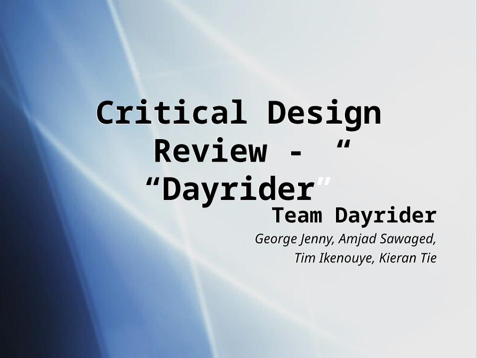
Minimum: A solar-powered, router-controlled RC vehicle
Target: A self-controlled software-sensor interface with regenerative techniques for energy recapture measurements
Optimal: A vehicle that combines efficient design, functional power management, and a dynamic user interface in an aesthetically pleasing package
04/19/23 CDR - Team Dayrider 3
StatusStatus
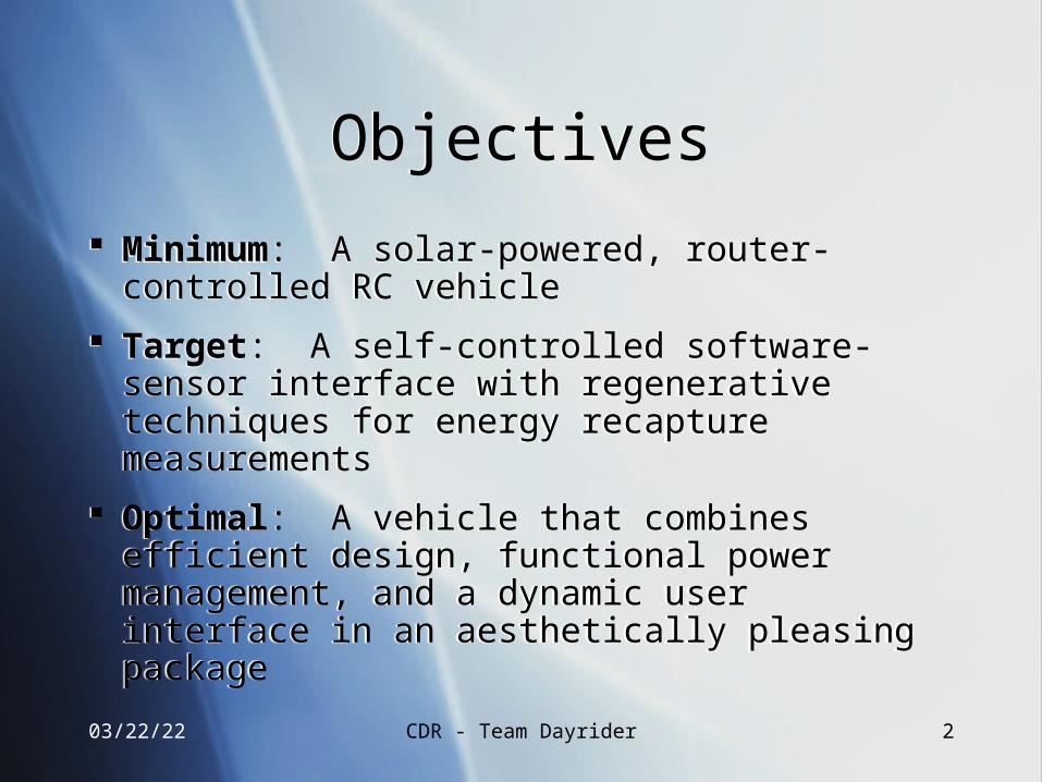
Components selected and shipping Preliminary wire-wrapping of modular
pieces (ADCs) Control software of the MSP430 I.P. Schematics: main board, subsystems
sketched out and transferring to Altium Router hardware/software modifications
completed
Components selected and shipping Preliminary wire-wrapping of modular
pieces (ADCs) Control software of the MSP430 I.P. Schematics: main board, subsystems
sketched out and transferring to Altium Router hardware/software modifications
completed
04/19/23 CDR - Team Dayrider 4
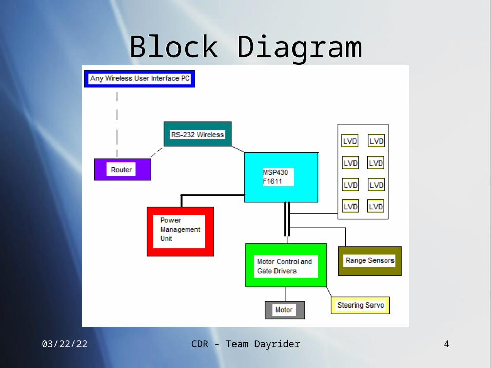
Block DiagramBlock Diagram
04/19/23 CDR - Team Dayrider 5
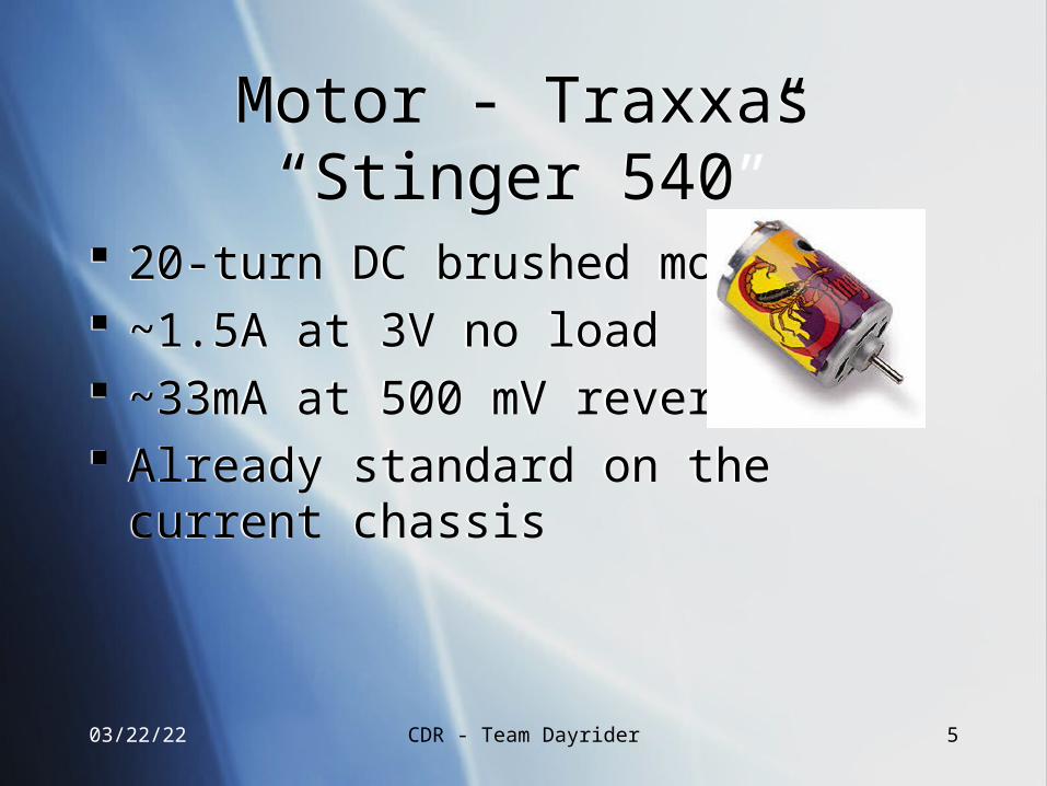
Motor - Traxxas “Stinger 540”Motor - Traxxas “Stinger 540”
20-turn DC brushed motor ~1.5A at 3V no load ~33mA at 500 mV reverse Already standard on the current chassis
20-turn DC brushed motor ~1.5A at 3V no load ~33mA at 500 mV reverse Already standard on the current chassis
04/19/23 CDR - Team Dayrider 6
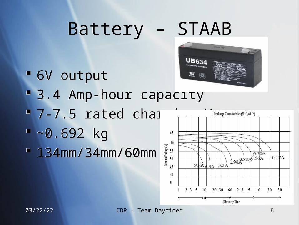
Battery – STAABBattery – STAAB
6V output 3.4 Amp-hour capacity 7-7.5 rated charging V ~0.692 kg 134mm/34mm/60mm
6V output 3.4 Amp-hour capacity 7-7.5 rated charging V ~0.692 kg 134mm/34mm/60mm
04/19/23 CDR - Team Dayrider 7
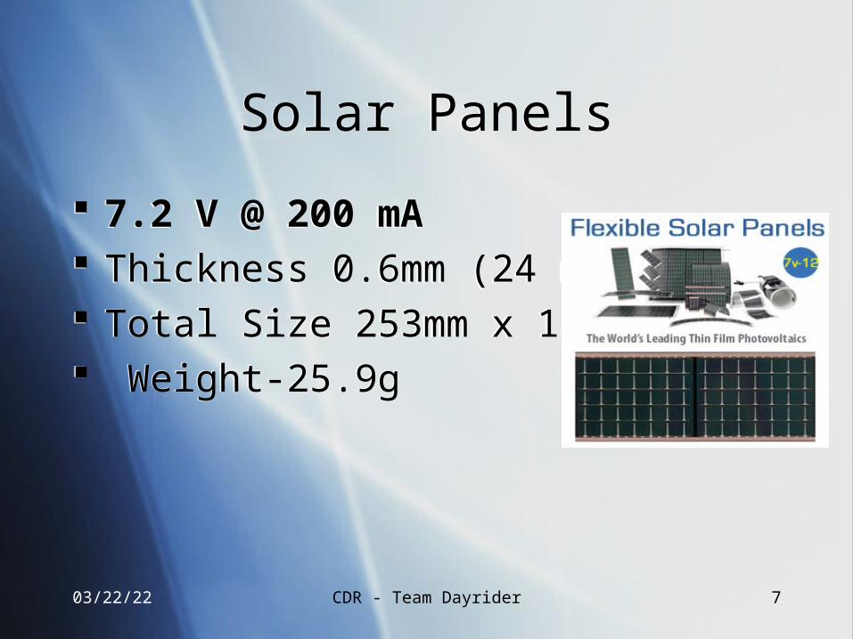
Solar PanelsSolar Panels
7.2 V @ 200 mA Thickness 0.6mm (24 mil) Total Size 253mm x 150mm Weight-25.9g
7.2 V @ 200 mA Thickness 0.6mm (24 mil) Total Size 253mm x 150mm Weight-25.9g
04/19/23 CDR - Team Dayrider 8
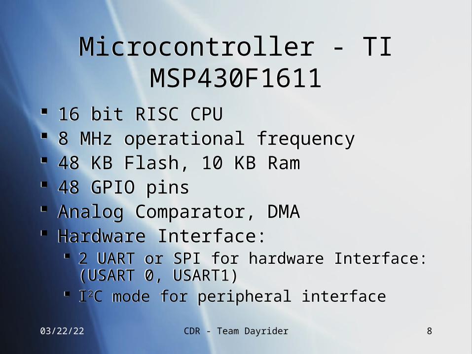
Microcontroller - TI MSP430F1611Microcontroller - TI MSP430F1611
16 bit RISC CPU 8 MHz operational frequency 48 KB Flash, 10 KB Ram 48 GPIO pins Analog Comparator, DMA Hardware Interface:
2 UART or SPI for hardware Interface: (USART 0, USART1)
I2C mode for peripheral interface
16 bit RISC CPU 8 MHz operational frequency 48 KB Flash, 10 KB Ram 48 GPIO pins Analog Comparator, DMA Hardware Interface:
2 UART or SPI for hardware Interface: (USART 0, USART1)
I2C mode for peripheral interface
04/19/23 CDR - Team Dayrider 9
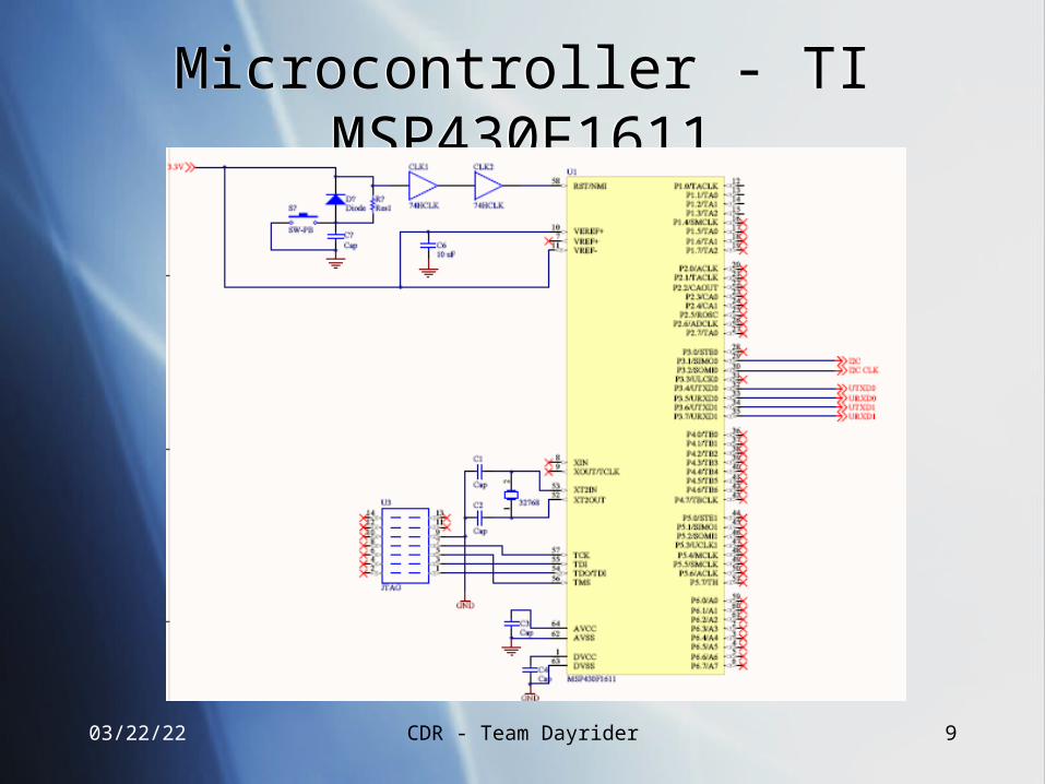
Microcontroller - TI MSP430F1611Microcontroller - TI MSP430F1611
04/19/23 CDR - Team Dayrider 10
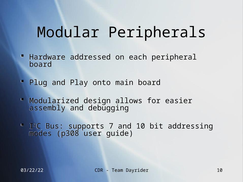
Modular PeripheralsModular Peripherals
Hardware addressed on each peripheral board
Plug and Play onto main board
Modularized design allows for easier assembly and debugging
I2C Bus: supports 7 and 10 bit addressing modes (p308 user guide)
Hardware addressed on each peripheral board
Plug and Play onto main board
Modularized design allows for easier assembly and debugging
I2C Bus: supports 7 and 10 bit addressing modes (p308 user guide)
04/19/23 CDR - Team Dayrider 11
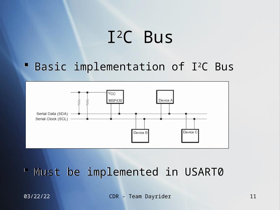
I2C BusI2C Bus
Basic implementation of I2C Bus
Must be implemented in USART0
Basic implementation of I2C Bus
Must be implemented in USART0
04/19/23 CDR - Team Dayrider 12
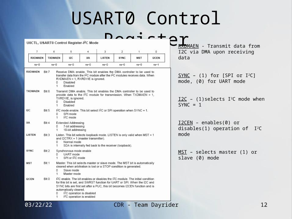
USART0 Control RegisterUSART0 Control RegisterRXDMAEN - Transmit data from I2C via DMA upon receiving data
SYNC – (1) for [SPI or I2C] mode, (0) for UART mode
I2C – (1)selects I2C mode when SYNC = 1
I2CEN – enables(0) or disables(1) operation of I2C mode
MST – selects master (1) or slave (0) mode
04/19/23 CDR - Team Dayrider 13
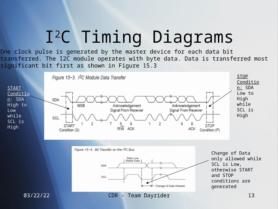
I2C Timing DiagramsI2C Timing DiagramsOne clock pulse is generated by the master device for each data bittransferred. The I2C module operates with byte data. Data is transferred mostsignificant bit first as shown in Figure 15.3
START Condition: SDA High to Low while SCL is High
STOP Condition: SDA Low to High while SCL is High
Change of Data only allowed while SCL is Low, otherwise START and STOP conditions are generated
04/19/23 CDR - Team Dayrider 14
I2C Addressing SchemeI2C Addressing Scheme
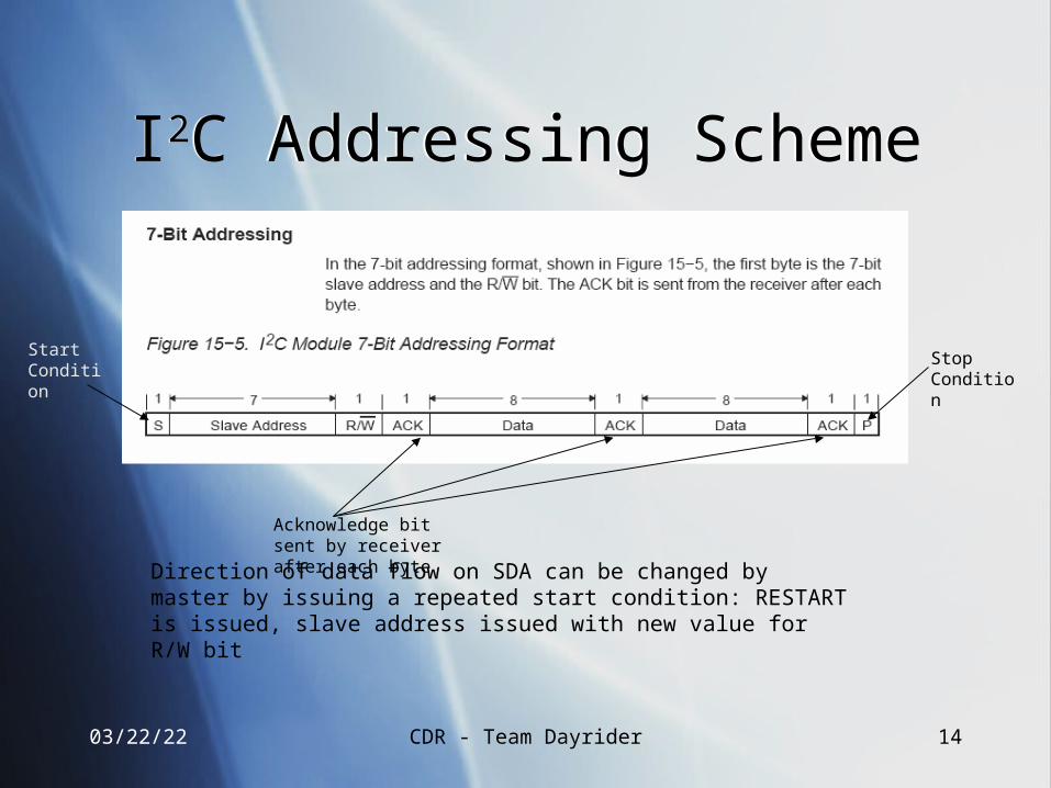
Start Condition
Acknowledge bit sent by receiver after each byte
Stop Condition
Direction of data flow on SDA can be changed by master by issuing a repeated start condition: RESTART is issued, slave address issued with new value for R/W bit
04/19/23 CDR - Team Dayrider 15
Motor Controller - LMD18200TMotor Controller - LMD18200T
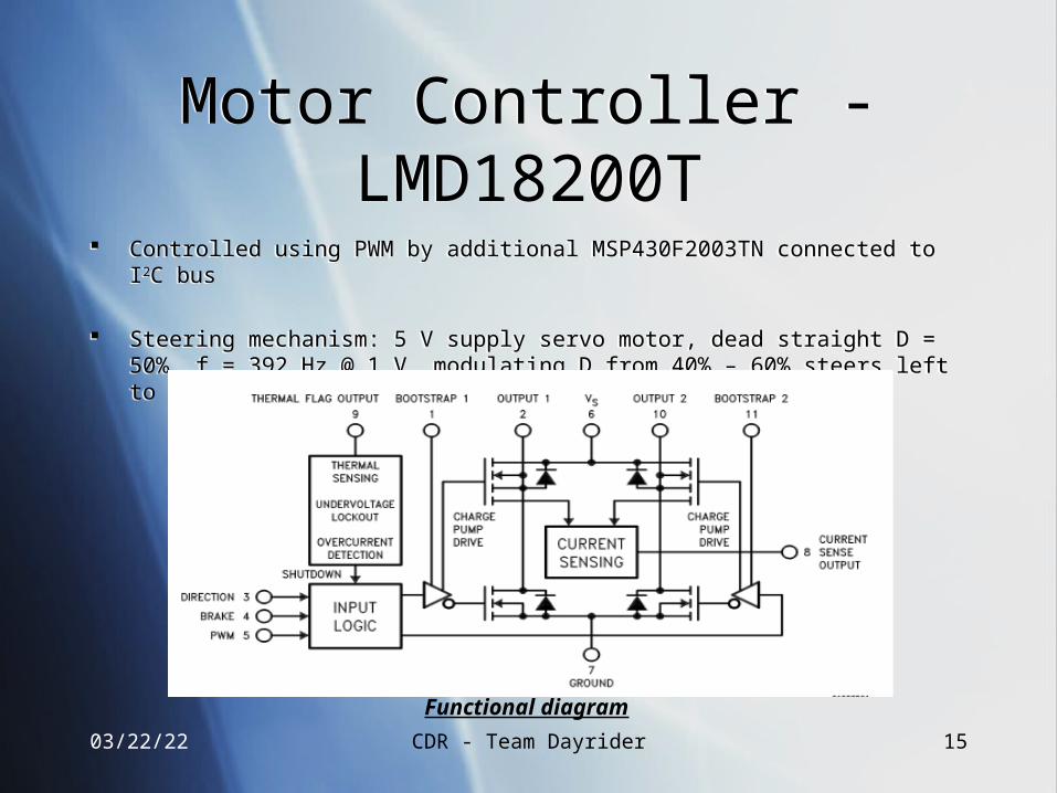
Controlled using PWM by additional MSP430F2003TN connected to I2C bus
Steering mechanism: 5 V supply servo motor, dead straight D = 50%, f = 392 Hz @ 1 V, modulating D from 40% – 60% steers left to right.
Controlled using PWM by additional MSP430F2003TN connected to I2C bus
Steering mechanism: 5 V supply servo motor, dead straight D = 50%, f = 392 Hz @ 1 V, modulating D from 40% – 60% steers left to right.
Functional diagram
04/19/23 CDR - Team Dayrider 16
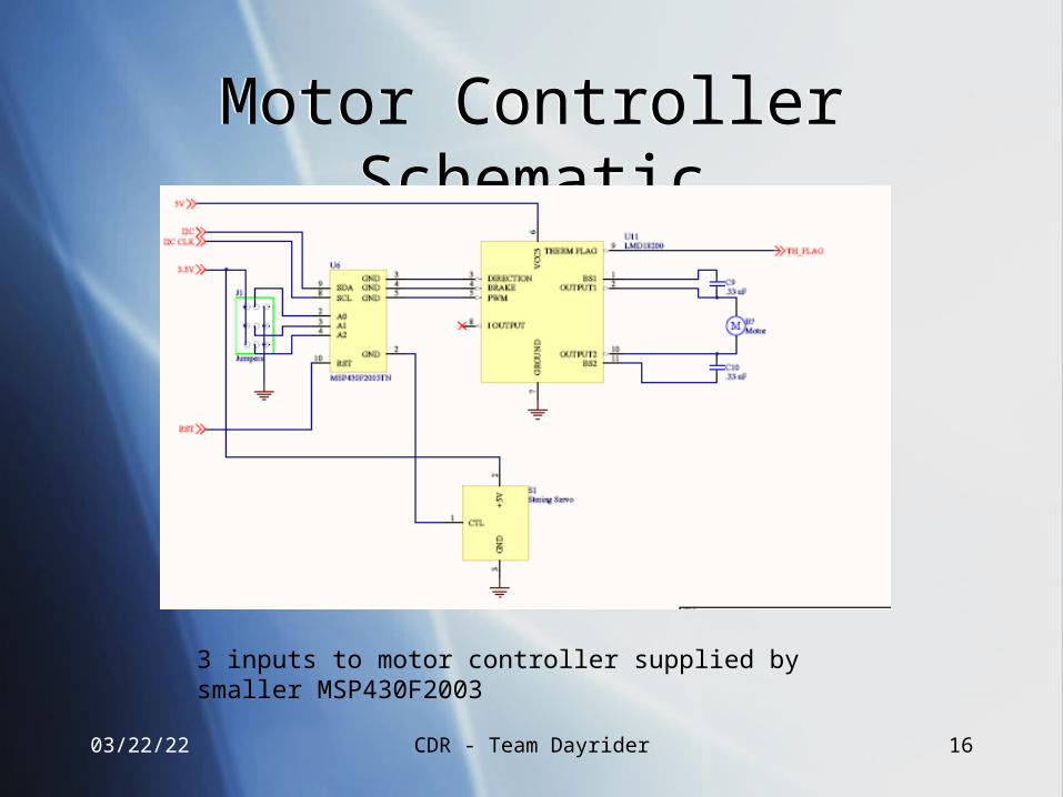
Motor Controller SchematicMotor Controller Schematic
3 inputs to motor controller supplied by smaller MSP430F2003
04/19/23 CDR - Team Dayrider 17
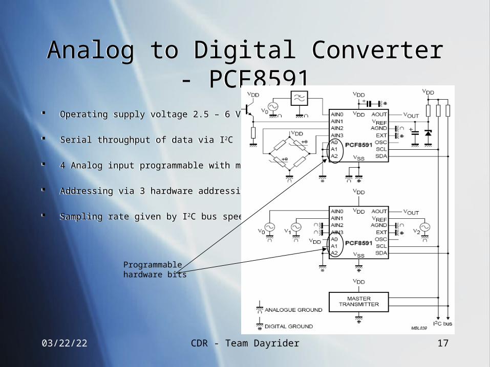
Analog to Digital Converter - PCF8591Analog to Digital Converter - PCF8591
Operating supply voltage 2.5 – 6 V
Serial throughput of data via I2C
4 Analog input programmable with multiplexer
Addressing via 3 hardware addressing pins
Sampling rate given by I2C bus speed
Operating supply voltage 2.5 – 6 V
Serial throughput of data via I2C
4 Analog input programmable with multiplexer
Addressing via 3 hardware addressing pins
Sampling rate given by I2C bus speed
Programmable hardware bits
04/19/23 CDR - Team Dayrider 18
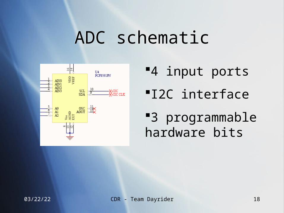
ADC schematicADC schematic
4 input ports
I2C interface
3 programmable hardware bits
04/19/23 CDR - Team Dayrider 19
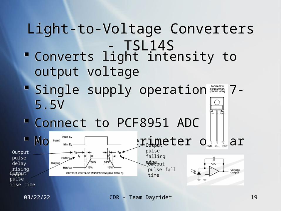
Light-to-Voltage Converters - TSL14SLight-to-Voltage Converters - TSL14S Converts light intensity to output voltage Single supply operation 2.7-5.5V Connect to PCF8951 ADC Mount along perimeter of car
Converts light intensity to output voltage Single supply operation 2.7-5.5V Connect to PCF8951 ADC Mount along perimeter of car
Output pulse delay rising edge
Output pulse rise time
Output pulse falling edge
Output pulse fall time
04/19/23 CDR - Team Dayrider 20
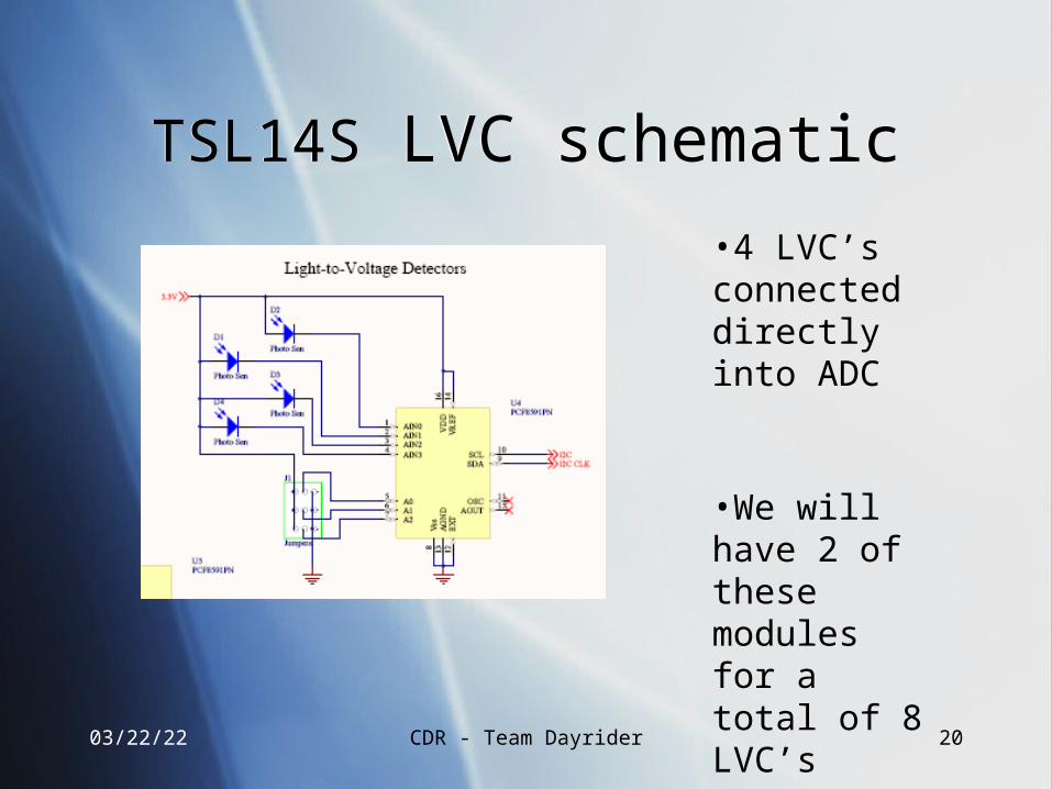
TSL14S LVC schematicTSL14S LVC schematic
•4 LVC’s connected directly into ADC
•We will have 2 of these modules for a total of 8 LVC’s
04/19/23 CDR - Team Dayrider 21
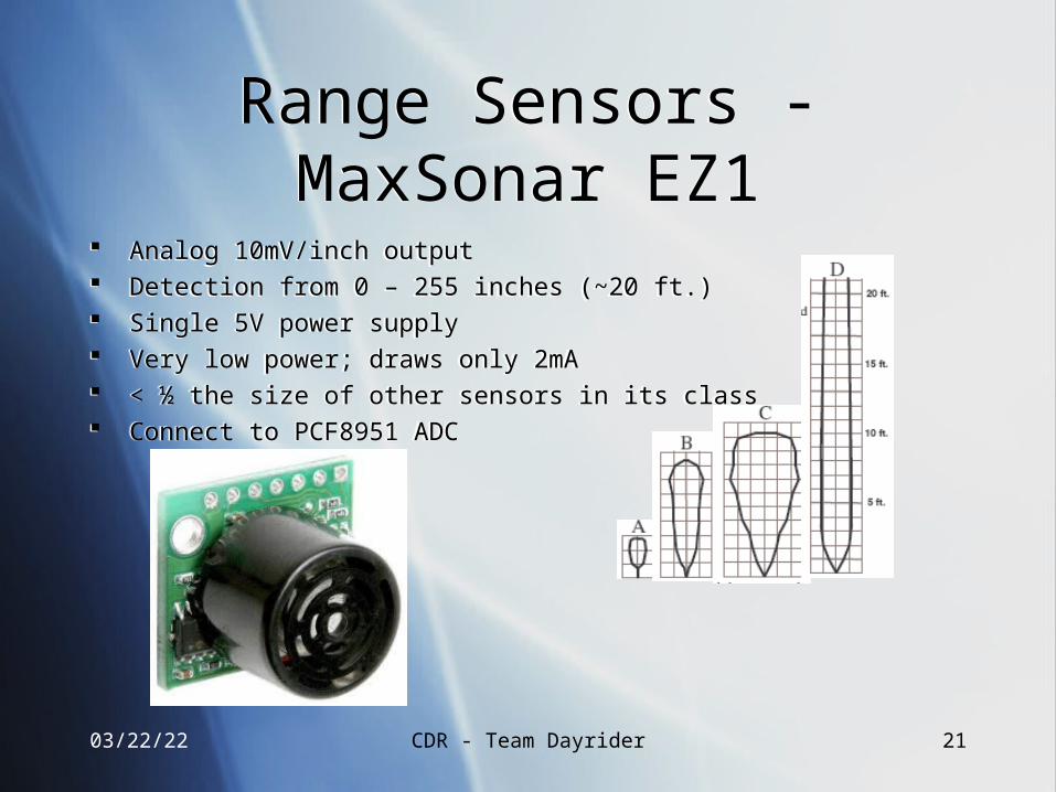
Range Sensors - MaxSonar EZ1Range Sensors - MaxSonar EZ1
Analog 10mV/inch output Detection from 0 – 255 inches (~20 ft.) Single 5V power supply Very low power; draws only 2mA < ½ the size of other sensors in its class Connect to PCF8951 ADC
Analog 10mV/inch output Detection from 0 – 255 inches (~20 ft.) Single 5V power supply Very low power; draws only 2mA < ½ the size of other sensors in its class Connect to PCF8951 ADC
04/19/23 CDR - Team Dayrider 22
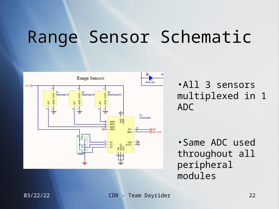
Range Sensor SchematicRange Sensor Schematic
•All 3 sensors multiplexed in 1 ADC
•Same ADC used throughout all peripheral modules
04/19/23 CDR - Team Dayrider 23
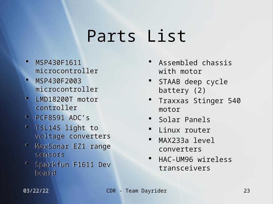
Parts ListParts List Assembled chassis with motor STAAB deep cycle battery (2) Traxxas Stinger 540 motor Solar Panels Linux router MAX233a level converters HAC-UM96 wireless
transceivers
Assembled chassis with motor STAAB deep cycle battery (2) Traxxas Stinger 540 motor Solar Panels Linux router MAX233a level converters HAC-UM96 wireless
transceivers
MSP430F1611 microcontroller MSP430F2003 microcontroller LMD18200T motor controller PCF8591 ADC’s TSL14S light to voltage
converters MaxSonar EZ1 range sensors Sparkfun F1611 Dev board
MSP430F1611 microcontroller MSP430F2003 microcontroller LMD18200T motor controller PCF8591 ADC’s TSL14S light to voltage
converters MaxSonar EZ1 range sensors Sparkfun F1611 Dev board
04/19/23 CDR - Team Dayrider 24
Serial Communication - MAX233eSerial Communication - MAX233e
Converts TTL/CMOS levels coming from router/microcontroller to RS232 levels for computer/HAC-UM96
2 needed - one for router, and one for microcontroller/UART
Converts TTL/CMOS levels coming from router/microcontroller to RS232 levels for computer/HAC-UM96
2 needed - one for router, and one for microcontroller/UART
04/19/23 CDR - Team Dayrider 25
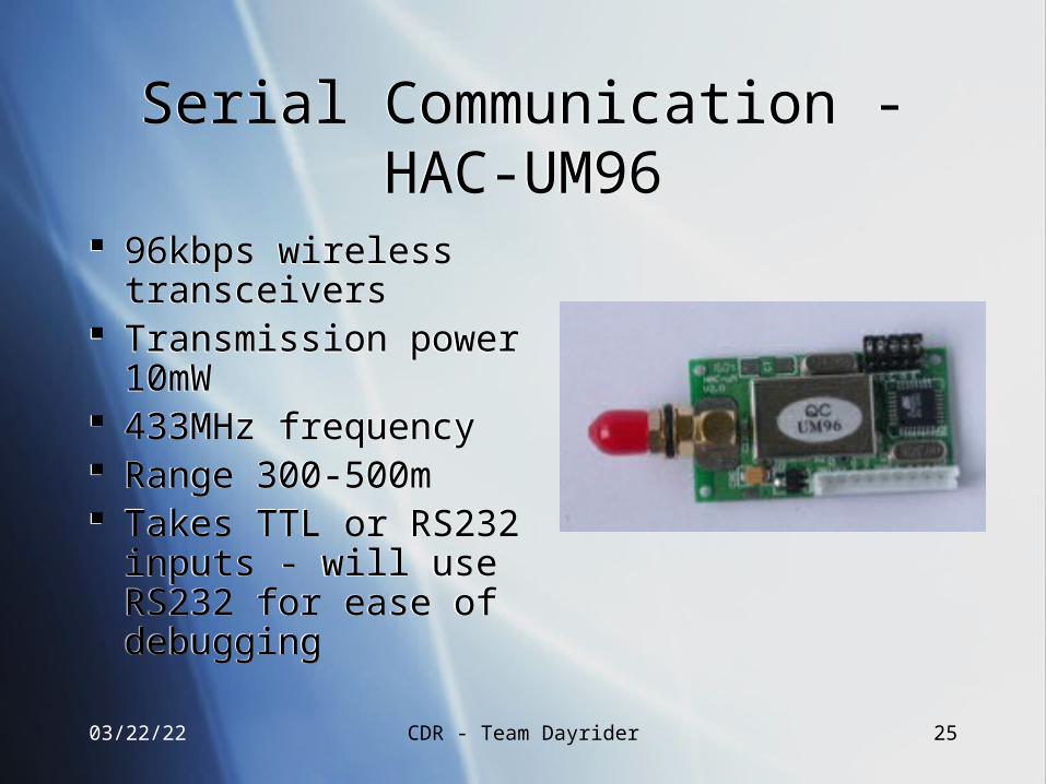
Serial Communication - HAC-UM96Serial Communication - HAC-UM96
96kbps wireless transceivers
Transmission power 10mW
433MHz frequency Range 300-500m Takes TTL or RS232
inputs - will use RS232 for ease of debugging
96kbps wireless transceivers
Transmission power 10mW
433MHz frequency Range 300-500m Takes TTL or RS232
inputs - will use RS232 for ease of debugging
04/19/23 CDR - Team Dayrider 26
Software - MSP430Software - MSP430
Written in C / Assembly Developed using IAR
Embedded Workbench Tested on prototyping board
from Olimex Final version transferred to
main circuit
Written in C / Assembly Developed using IAR
Embedded Workbench Tested on prototyping board
from Olimex Final version transferred to
main circuit
QuickTime™ and aTIFF (Uncompressed) decompressor
are needed to see this picture.
No software yet, but… No software yet, but…
04/19/23 CDR - Team Dayrider 27
Software - MSP430Software - MSP430 Use Cases - Outline
software algorithms for the operation of the vehicle UC1 - Avoid Obstacle UC2 - Drive to Sunlight UC3 - Drive Vehicle
Test cases for all possible paths of use cases
Domain model under construction…
Use Cases - Outline software algorithms for the operation of the vehicle UC1 - Avoid Obstacle UC2 - Drive to Sunlight UC3 - Drive Vehicle
Test cases for all possible paths of use cases
Domain model under construction…
04/19/23 CDR - Team Dayrider 28
Software - Linksys WRT54GSoftware - Linksys WRT54G Linux - OpenWRT lighttpd - web
server Ajax - live updating
of site PHP - system
commands
Serial data processor
Linux - OpenWRT lighttpd - web
server Ajax - live updating
of site PHP - system
commands
Serial data processor
QuickTime™ and aTIFF (Uncompressed) decompressor
are needed to see this picture.
04/19/23 CDR - Team Dayrider 29
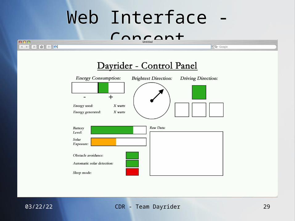
Web Interface - ConceptWeb Interface - Concept
04/19/23 CDR - Team Dayrider 30
Web Interface - DemoWeb Interface - Demo
04/19/23 CDR - Team Dayrider 31
Division of LaborDivision of Labor
Software Kieran & Amjad User’s Interface (webpage) Autonomous Control Peripherals
Hardware Tim & George Wire-wrap board Peripherals Regenerative Braking
Software Kieran & Amjad User’s Interface (webpage) Autonomous Control Peripherals
Hardware Tim & George Wire-wrap board Peripherals Regenerative Braking
04/19/23 CDR - Team Dayrider 32
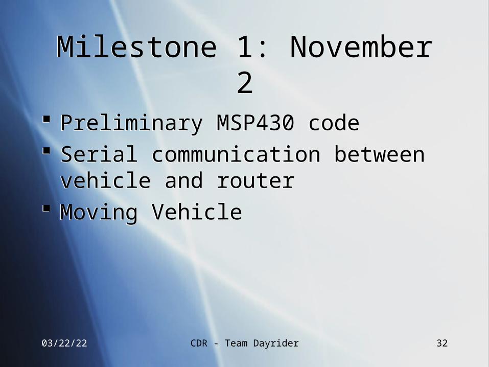
Milestone 1: November 2Milestone 1: November 2
Preliminary MSP430 code Serial communication between vehicle and
router Moving Vehicle
Preliminary MSP430 code Serial communication between vehicle and
router Moving Vehicle
04/19/23 CDR - Team Dayrider 33
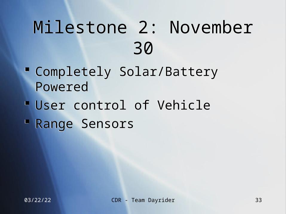
Milestone 2: November 30Milestone 2: November 30
Completely Solar/Battery Powered User control of Vehicle Range Sensors
Completely Solar/Battery Powered User control of Vehicle Range Sensors
04/19/23 CDR - Team Dayrider 34
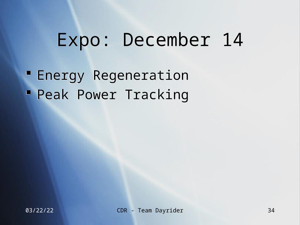
Expo: December 14Expo: December 14
Energy Regeneration Peak Power Tracking
Energy Regeneration Peak Power Tracking
04/19/23 CDR - Team Dayrider 35
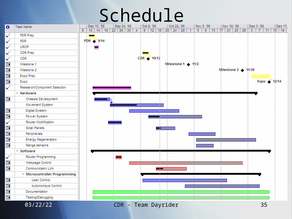
ScheduleSchedule

04/19/23 CDR - Team Dayrider 36
Questions?Questions?