Embed Size (px)
Citation preview

www.eepowersolutions.com
www.technical-sys.com
Keeping an Eye on Your Critical Power!
Battery MonitoringBattery Testers
Digital Hydrometers
AC / DC Load BanksBattery ChargersIEEE / NERC Kits
Ground Fault LocatorsGas Detectors
Battery Data Logging
Critical Battery Monitoring, Testing, & Charging Solutions2014 Product Catalog

Mis
sion
E
agle
Eye
Pow
er S
olut
ions
Eagle Eye Power Solutions (EEPS)The BEST Battery Testing Equipment.The BEST Customer Support. PERIOD.
Eagle Eye MissionTo lead the industry in battery testing education, training, products and support. Being the industry leader requires outstanding products, support services and overall value, so that every customer is 100% satisfied with their EEPS experience.
Mis
sion
E
agle
Eye
Pow
er S
olut
ions
Benefits of Doing Business with EEPS• Our Manufacturing facilities have been producing quality products since 1984• Our products are held to the highest standards• Priority in response time and customer support• All customers have access to free training and continued support • Focused on building long-term, mutually beneficial relationships
Eagle Eye Customer SupportEvery employee and representative of EEPS is properly trained to understand our products and our core values. Our response time and support to customers is always a main priority. From the initial contact with the customer, throughout the education & sales process and continuing on with after sales support – we are there for our customers every step if the way! When working with EEPS the customer will NEVER feel that they are taken for granted. Everyone that works with EEPS will understand that customer satisfaction is truly a guarantee. At EEPS we are always focused on building a long-term, mutually beneficial relationships (“lifetime customers”). We always encourage customer feedback regarding ways that we can improve our products and support to better fit their needs.
Eagle Eye World Class ProductsEagle Eye products are manufactured at ISO-certified, World Class production & testing facilities. With the research and development efforts that include collaborative efforts by leading universities and world famous research institutes, our customers can be confident they are receiving the best products available in the industry.

iPQMS Battery Monitoring System
To Order Call Toll Free:1-877-805-3377
Model # IPQMS
Main Processing Unit (MPU)
Product DescriptionThe iPQMS Battery Monitoring System is designed to measure the aging status of up to 448 jars (or 448 cells) by measuring and recording: string voltage, DC current, jar/cell voltage, internal resistance (I.R.), connection resistance, and temperature. The iPQMS is designed for use on vented lead acid, valve regulated lead acid, and nickel-cadmium battery systems.
The included Centroid Snet Battery Management Software records measured data for comprehensive trending analysis, ensuring backup power systems are optimally maintained. The iPQMS system measures up to 448 jars (or 448 cells) through clamps connected directly to the battery connections. The iPQMS can be used on a private network via TCP/IP or locally with direct RS-232 connection. Networked systems can utilize SMS/Email alerts during alarm outbreak. Modbus protocol can be utilized for third-party software integration.
Product Advantages• 24/7/365 Battery Monitoring• Comprehensive Battery Management
Software• Installation while systems are online• Meets IEEE and NERC standard
recommendations for battery monitoring• Patented ripple-removing algorithm• Injects minimal current for measurement• Simple to install with custom, pre-
assembled installation materials• Alarms alert in real-time during outbreak• Can be powered by AC or DC
Battery Management Software• Displays and records string
voltage, string DC current, cell voltage, cell I.R., & cell temperature for all battery systems
• Trending analysis of measured parameters on a string or jar/cell level
• Report generation & ability to export measured data to Excel
• Send commands to iPQMS systems
• Detailed log of alarm outbreaks with Email/SMS alerts
• Automatically record, save, & playback discharge & recharge events
iPQMS Installation on 125VDC Battery System
Batte
ry M
onito
ring
Syst
ems
IB
wat
ch-S
ERIE
S
3
Centroid Snet Battery Management Software
Technical Specifications
Measurement Range:
Battery Capacity: 5 – 6,000 AhJar/Cell Voltage: 1 – 16 VDCAC Voltage/ Current: 0 – 600 VAC / 999.9 ADC Voltage/Current: ~ 999.9 VDC / ~999.9 A
Accuracy:
DC Voltage / Current: ±0.5% / ±1%Temperature: ±2%Internal Resistance: ±2%Cell Voltage: ±1%
Resolution:
AC Voltage / Current: 0.1 V / 0.1 ADC Voltage / Current: 0.1 V / 0.1 ACell Voltage: 10 mVInternal Resistance: 0.001 ΩTemperature: 0.5 °C (0.5 °F)
Test Speed / Test Load: 3 – 4 seconds per cell at less than 2 A per cell
Measuring Interval: Adjustable from 5 min to 24 hours (voltage & I.R.)
Data Transfer: TCP/IP via Ethernet, RS-232, Modbus
Display: Backlit LCD
Internal Storage: Approximately 1 month backup
Operating Environment: Temperature: 0 – 65 °C (32 – 150 °F)Relative Humidity: Under 80%
Power Requirements: Input: 43 – 250 VDC / 110 – 220 VACConsumption: 15 W
Dimensions: MPU: 290 x 280 x 90 mm (11.4 x 11 x 3.5 in)RU: 310 x 178 x 85 mm (12.2 x 5.9 x 3.3 in)
Ordering InformationNo. Model # Description
1 IPQMS Battery Monitoring Solutions: Up to 448 Jars/Cells
System Includes• Centroid Snet Battery
Management Software• iPQMS MPU with mounting kit• Relaying Unit(s)• O-Clamps for inter-cell cable
connections• C-Clamps for inter-cell busbar
connections• Cabling for string voltage
measurement• Cabling for cell voltage, cell I.R.
and temp. measurement• CT clamp for DC current
measurement• Power cabling• Optional: Spare parts kit
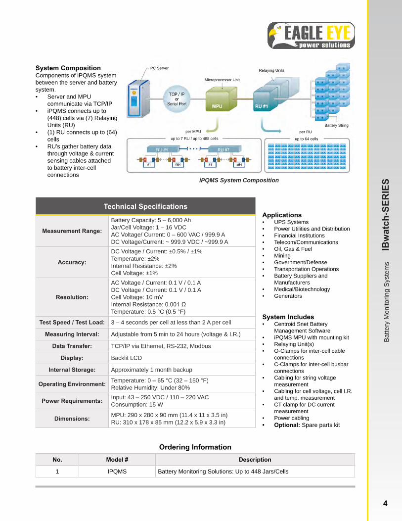
iPQMS System Composition
System CompositionComponents of iPQMS system between the server and battery system. • Server and MPU
communicate via TCP/IP• iPQMS connects up to
(448) cells via (7) Relaying Units (RU)
• (1) RU connects up to (64) cells
• RU’s gather battery data through voltage & current sensing cables attached to battery inter-cell connections
Applications• UPS Systems• Power Utilities and Distribution• Financial Institutions• Telecom/Communications• Oil, Gas & Fuel• Mining• Government/Defense• Transportation Operations• Battery Suppliers and
Manufacturers• Medical/Biotechnology• Generators
Batte
ry M
onito
ring
Syst
ems
IB
wat
ch-S
ERIE
S
4
PC Server
Microprocessor Unit
up to 7 RU / up to 488 cells up to 64 cells
per RUper MPUBattery String
Relaying Units

iPQMS-Pro Battery Monitoring System
To Order Call Toll Free:1-877-805-3377
Model # IPQMS-Pro
iPQMS-Pro Main Processing Unit
Product DescriptionThe iPQMS-Pro Battery Monitoring System is a scalable system designed to monitor the health of critical battery sys-tems by measuring: string voltage and current, jar/cell voltage and impedance, connection resistance, and temperature. The iPQMS-Pro measures critical battery parameters via clamps connected to the battery connections. A single system includes an MPU (Main Processing Unit) and all required cables and clamps for installation. One MPU can connect to (48) cells, however up to ten MPU’s can be configured in daisy-chain for monitoring of up to (480) cells. Measured data is communicat-ed via TCP/IP or RS-232 back to the included Centroid Snet Battery Management Software.
The iPQMS-Pro records, trends, and reports data against us-er-defined tolerances. In the event that a measured parameter is out of tolerance, an outbreak alarm will occur in the software and Email/SMS alerts will be generated. The iPQMS-Pro is an ideal solution for monitoring and predicting the health and performance of UPS Cabinets, Telecom Systems, and other backup power systems.Advantages
• 24/7/365 Battery Monitoring• Designed specifically around UPS battery systems• Meets IEEE and NERC standard recommendations
for battery monitoring• Patented ripple-removing algorithm• Injects minimal current for measurement• Simple to install with custom, pre-assembled
installation materials• Alerts in realtime during alarm outbreak
Batte
ry M
onito
ring
Syst
ems
IB
wat
ch-S
ERIE
S
5 www.eepowersolutions.com | toll free: 1-877-805-3377 | fax: 1-414-962-3660 | [email protected]
Centroid Snet Battery Management Software
Battery Management Software• Displays and records string
voltage, string DC current, cell voltage, cell I.R., & cell temperature for all battery systems
• Trending analysis of measured parameters on a string or jar/cell level
• Report generation & ability to export measured data to Excel
• Send commands to iPQMS systems
• Detailed log of alarm outbreaks with Email/SMS alerts
• Automatically record, save, & playback discharge & recharge events
iPQMS-Pro Side Connections

Technical Specifications
Measurement Range:
Battery Capacity: 10 – 6,000 AhJar/Cell Voltage: 0.1 – 16 VDCString DC Voltage: 0 – 900 VDCDC Current: 0 – 3000 AmpsInternal Resistance: 0.001 – 99.999 mΩ
Accuracy:
DC Voltage / Current: ±0.5% / ±1%Temperature: ±2%Internal Resistance: ±2%Cell Voltage: ±1%
Resolution:
DC Voltage / Current: 0.1 V / 0.1 AmpsCell Voltage: 10 mVInternal Resistance: 0.001 ΩTemperature: 0.1 °C (0.1 °F)
Test Speed / Test Load: 2 seconds per cell / Less than 2 Amps per cell
Measuring Interval: Adjustable from 4 min. to once per day (voltage & resistance)
Data Transfer: TCP/IP, RS-232
Display: Status LED
Operating Environment: Temperature: 0 - 65 °C (32 - 150 °F) Relative Humidity: Under 80%
Power Requirements: 40 – 60 VDC / 100 - 240 VAC
Dimensions: 370 x 230 x 60 mm (14.6 x 9 x 2.4 in)
Ordering InformationNo. Model # Description
1 IPQMS-Pro Battery Monitoring Solutions: Up to 48 Jars (or 48 cells)
Applications• UPS Cabinets• Telecom/Communications• Power Utilities and Distribution• Financial Institutions• Oil, Gas & Fuel• Mining• Government/Defense• Transportation Operations• Battery Suppliers and
Manufacturers• Medical/Biotechnology• Generators
System Composition:Components of iPQMS-Pro between the server and battery system. • Server and MPU(s)
communicate via TCP/IP
• (1) MPU connects up to (48) cells
• Up to (10) MPUs can be connected in daisy chain for a total of (480) cells connections
• MPU’s gather battery data through voltage & currentsensing cables connected to each cell
Server PCWith Monitoring Software
SMS Alerts Jar/Cell ConnectionsUp to (48) Per MPU
iPQMS-Pro MPUUp to (10) in Daisy-Chain
Batte
ry M
onito
ring
Syst
ems
IB
wat
ch-S
ERIE
S
6www.eepowersolutions.com | toll free: 1-877-805-3377 | fax: 1-414-962-3660 | [email protected]
System Includes• Centroid Snet Battery
Management Software• iPQMS-Pro with mounting kit• O-Clamps for inter-cell cable
connections• C-Clamps for inter-cell busbar
connections• Cabling for string voltage
measurement• Cabling for cell voltage, cell I.R.
and temp. measurement• CT clamp for DC current
measurement• Power cabling• Optional: Spare parts kit
BDS-Pro Battery Monitoring System
To Order Call Toll Free:1-877-805-3377
Model # BDS-Pro
Main Processing Unit (MPU)
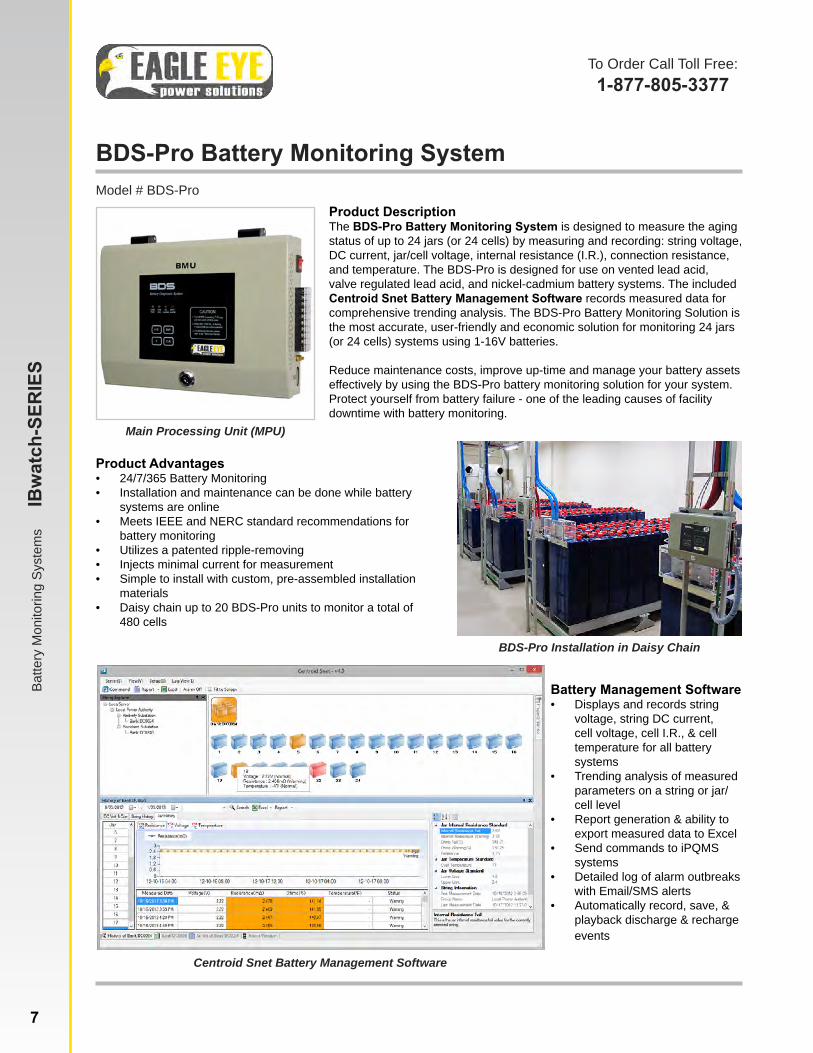
Product DescriptionThe BDS-Pro Battery Monitoring System is designed to measure the aging status of up to 24 jars (or 24 cells) by measuring and recording: string voltage, DC current, jar/cell voltage, internal resistance (I.R.), connection resistance, and temperature. The BDS-Pro is designed for use on vented lead acid, valve regulated lead acid, and nickel-cadmium battery systems. The included Centroid Snet Battery Management Software records measured data for comprehensive trending analysis. The BDS-Pro Battery Monitoring Solution is the most accurate, user-friendly and economic solution for monitoring 24 jars (or 24 cells) systems using 1-16V batteries.
Reduce maintenance costs, improve up-time and manage your battery assets effectively by using the BDS-Pro battery monitoring solution for your system. Protect yourself from battery failure - one of the leading causes of facility downtime with battery monitoring.
Product Advantages• 24/7/365 Battery Monitoring• Installation and maintenance can be done while battery
systems are online• Meets IEEE and NERC standard recommendations for
battery monitoring• Utilizes a patented ripple-removing • Injects minimal current for measurement• Simple to install with custom, pre-assembled installation
materials• Daisy chain up to 20 BDS-Pro units to monitor a total of
480 cells
Batte
ry M
onito
ring
Syst
ems
IB
wat
ch-S
ERIE
S
BDS-Pro Installation in Daisy Chain
7 www.eepowersolutions.com | toll free: 1-877-805-3377 | fax: 1-414-962-3660 | [email protected]
Centroid Snet Battery Management Software
Battery Management Software• Displays and records string
voltage, string DC current, cell voltage, cell I.R., & cell temperature for all battery systems
• Trending analysis of measured parameters on a string or jar/cell level
• Report generation & ability to export measured data to Excel
• Send commands to iPQMS systems
• Detailed log of alarm outbreaks with Email/SMS alerts
• Automatically record, save, & playback discharge & recharge events

Technical Specifications
Measurement Range:Battery Capacity: 5 – 6,000 AhJar/Cell Voltage: 1 – 16 VDCDC Voltage/Current: ~ 999.9 VDC/~999.9 A
Accuracy:
DC Voltage / Current: ±0.5% / ±1%Temperature: ±2%Internal Resistance: ±2%Cell Voltage: ±1%
Resolution:
AC Voltage / Current: 0.1 V / 0.1 ADC Voltage / Current: 0.1 V / 0.1 ACell Voltage: 10 mVInternal Resistance: 0.001 mΩTemperature: 0.5 °C (0.5 °F)
Test Speed / Test Load: 3 – 4 seconds per cell / less than 2 A per cell
Measuring Interval: Adjustable from 5 min – 24 hours (voltage & resistance)
Data Transfer: TCP/IP, RS-232 to USB, MODBUS, SMS
Display: LED Indicator Light
Operating Environment: Temperature: 0 – 65 °C (32 – 150 °F)Relative Humidity: Under 80%
Power Requirements: Input: 38 – 58 VDC (from connected batteries)Consumption: 10 W
Dimensions: 195 x 270 x 55 mm (7.7 x 10.6 x 2.2 in)
Ordering InformationNo. Model # Description
1 BDS-Pro Battery Monitoring Solutions: Up to 24 Jars/Cells
Common Applications• Telecom/Communications• Power Utilities and
Distribution• Transportation Operations• Oil, Gas & Fuel• Generators• UPS Systems
Batte
ry M
onito
ring
Syst
ems
IB
wat
ch-S
ERIE
S
System CompositionComponents of BDS-Pro system between the server and battery system. • Server and MPU communicate via TCP/IP• BDS-Pro MPU connects up to (24) cells• Up to (20) MPU’s can be daisy chained to measure (480)
cells• MPU’s gather battery data through voltage & current
sensing cables connected to each cell
BDS-Pro System CompositionBDS-Pro Installation
8
Battery String
PC Server
Microprocessor Unit
per MPUup to 24 cells
www.eepowersolutions.com | toll free: 1-877-805-3377 | fax: 1-414-962-3660 | [email protected]
System Includes• Centroid Snet Battery
Management Software• BDS-Pro with mounting kit• O-Clamps for inter-cell cable
connections• C-Clamps for inter-cell busbar
connections• Cabling for string voltage
measurement• Cabling for cell voltage, cell
I.R. and temp. measurement• CT clamp for DC current
measurement• Power cabling• Optional: Spare parts kit

BMS-icom Battery Monitoring System
To Order Call Toll Free:1-877-805-3377
Model # BMS-icom
BMS-icom
Product Advantages• 24/7/365 Battery Monitoring• Installation and maintenance can be done while battery
systems are online• Meets IEEE and NERC standard recommendations for
battery monitoring• Utilizes a patented ripple-removing algorithm • Injects minimal current for measurement• Simple to install with custom, pre-assembled materials• Designed for 48V systems (12V cells)• Alerts in real-time during outbreak
Batte
ry M
onito
ring
Syst
ems
IB
wat
ch-S
ERIE
S
BMS-icom Installation
9 www.eepowersolutions.com | toll free: 1-877-805-3377 | fax: 1-414-962-3660 | [email protected]
Centroid Snet Battery Management Software
Battery Management Software• Displays and records string
voltage, string DC current, cell voltage, cell I.R., & cell temperature for all battery systems
• Trending analysis of measured parameters on a string or jar/cell level
• Report generation & ability to export measured data to Excel
• Send commands to iPQMS systems
• Detailed log of alarm outbreaks with Email/SMS alerts
• Automatically record, save, & playback discharge & recharge events
Product DescriptionThe BMS-icom Battery Monitoring System is designed to measure the aging status of up to (4) 12V jars by measuring and recording: string voltage, DC current, jar/cell voltage, internal resistance (I.R.), connection resistance, and temperature. The included Centroid Snet Battery Management Software displays and records measured data for comprehensive trending analysis. The BMS-icom is the most accurate, user-friendly, and cost effective solution for monitoring 48VDC systems using (4) 12V batteries.
Reduce maintenance costs, improve up-time and manage your battery assets effectively by using the BMS-icom battery monitoring solution for your 48V system. Real-time battery monitoring also reduces maintenance and replacement costs by maximizing your battery life.

Technical Specifications
Battery Types: VLA, VRLA, NiCad, & Others
Measurement Range:Battery Capacity: 5 – 6,000 AhJar/Cell Voltage: 12 VDCDC Voltage/Current: ~ 999.9 VDC/~999.9 A
Accuracy:
DC Voltage / Current: ±0.5% / ±1%Temperature: ±2%Internal Resistance: ±2%Cell Voltage: ±1%
Resolution:
AC Voltage / Current: 0.1 V / 0.1 ADC Voltage / Current: 0.1 V / 0.1 ACell Voltage: 10 mVInternal Resistance: 0.001 ΩTemperature: 0.5 °C (0.5 °F)
Test Speed / Test Load: 3 – 4 seconds per cell / less than 2 A per cell
Measuring Interval: Adjustable from 5 min to 24 hours (voltage & resistance)
Data Transfer: TCP/IP, RS-232
Operating Environment:Temperature: 0 – 65 °C (32 – 150 °F)Relative Humidity: Under 80%
Power Requirements: 38 – 58 VDC (from connected batteries)
Dimensions: 140 x 121 x 44.5 mm (5.5 x 4.8 x 1.8 in)
Weight: 70 g (1.5 lbs)
Ordering InformationNo. Model # Description
1 BMS-icom Battery Monitoring Solutions: Up to 4 (12V) Jars/Cells
Common Applications• Generator backup• Telecom/Communications• Power Utilities and
Distribution• CATV Broadcasting
Batte
ry M
onito
ring
Syst
ems
IB
wat
ch-S
ERIE
S
System CompositionComponents of BMS-icom system between the server and battery system. • Server and MPU communicate
via TCP/IP• BMS-icom MPU connects up to
(4) cells• Connection fasted to inter-
cell-connection (cable or bus-bar)
• MPU gathers battery data through voltage & current sens-ing cables connected between each cell
• System current measured via current clamp
BMS-icom System Composition
10
PC Server
Microprocessor Unit
per MPUup to 4 cells
Battery String
www.eepowersolutions.com | toll free: 1-877-805-3377 | fax: 1-414-962-3660 | [email protected]
System Includes• Centroid Snet Battery
Management Software• BMS-icom• O-Clamps for inter-cell cable
connections• C-Clamps for inter-cell
busbar connections• Cabling for string voltage
measurement• Cabling for cell voltage, cell
I.R. and temp. measurement• CT clamp for DC current
measurement• Power cabling• Optional: Spare parts kit

IBEX-Series Portable Battery Testers
To Order Call Toll Free:1-877-805-3377
Model # IBEX-Series
IBEX-Ultra Kit
Product DescriptionThe IBEX-Series Portable Battery Testers are the fastest, smallest and most accurate battery testers in the industry today. Ensure reliability of backup power systems and prevent unexpected failures with the IBEX-Series. Eagle Eye Power Solutions offers multiple IBEX kit options to meet any company’s needs and budget. Test internal resistance (I.R.) or conductance, cell voltage, ripple current, temperature, and connection resistance to ensure you are testing per IEEE and NERC Recommendations.
The IBEX-Series is commonly used in the utility, telecommunications, UPS, transportation, and mission critical industries, and is the preferred battery tester by service groups worldwide. The IBEX injects a minimal test current into the tested batteries and precise & repeatable results appear in just 3 seconds. Battery Management Software is included with each IBEX-Series kit to easily identify bad cells, create reports, save data, and ensure the integrity of backup power systems.
Product Advantages• IEEE Recommended: Meets IEEE Std 1188-1996 and 2005 “Rec-
ommended Practice for Maintenance, Testing, and Replacement for Stationary Applications
• Precise & Repeatable: Utilizes a patented ripple-removing algo-rithm
• Durable: Simple design with no moving parts• Online Tester: Test batteries while they are in service• Fast: Automatically measures and stores data in just 3-4 seconds• Comprehensive Battery Diagnostic Software: Available software
provides an easy to use interface for data management, trending analysis, exporting to excel, viewing graphs and creating reports
• Battery Bank Management: Upload battery bank and alarm infor-mation to the IBEX from the included software
• Charging ripple current analysis (%) with IBEX-Ultra
Porta
ble
Batte
ry T
este
rs
IB
EX-S
ERIE
S
IBEX-Ultra with 4-Pin Test Leads and CT Clamp Meter
IBEX Kits Include
All IBEX Models:(Standard Kit)
IBEX Body, Soft-Poly-Vinyl Bag, 4-Pin Test Leads, Li-Ion Battery, USB Cable, Serial Comm Software, Standard Charger (100 to 240 VAC), Hard Plastic Carrying Case, User Manual
IBEX-Ultra :Exmons Ultra Software, Clip Test Leads, Temperature Probe, 0.5mΩ Shunt, Spare 4-Pin Test Lead Tips, IR Printer with Charger, Spare Paper Roll, DC Clamp Meter
IBEX-Pro: Exmons Pro Software, Clip Test Leads, Temperature Probe, 0.5mΩ Shunt, Spare 4-Pin Test Lead Tips, IR Printer with Charger, Spare Paper Roll
IBEX-1000: Exmons Pro Battery Management SoftwareIBEX-1000EX: Standard Kit
Optional: Modular Extender Rods with LED light (91 cm, 3 ft) for testing UPS cabinetsExtender Rods
11 www.eepowersolutions.com | toll free: 1-877-805-3377 | fax: 1-414-962-3660 | [email protected]

Technical SpecificationsBattery Types: VLA, VLRA, Ni-Cad, & Others
Parameters Measured: Internal Ohmic Resistance, Inter-Cell Resistance, Voltage, Tempera-ture, DC Current (Ultra), DC Ripple Current (Ultra)
Measurement Range:Battery Capacity: 5 – 6000 Ah Voltage: 0 – 60 VDC Ohmic Range: 0.001 – 999.9mΩ
Accuracy:DC Voltage: ±0.5% Internal Resistance: ±1.0% Temperature: ±2.0%
Resolution:DC Voltage: 10 mV Internal Resistance: 0.001 mΩ Temperature: 0.5 °C (0.5 °F)
Test Speed: 3 – 4 seconds per cell
Test Load: Less than 2 A per cell
Alarms: Voltage Over & Under, Resistance Warning & Fail, Temperature Over
Calibration Method: Auto Calibration
Data Transfer: USB Cable to PC
Display: Backlit LCD
Internal Storage: IBEX-Ultra: 4800 Results IBEX-Pro, 1000, 1000EX: 600 Results
Alarms: IBEX-Ultra: 80 AlarmsIBEX-Pro, 1000, 1000EX: 4 Alarms
Operating Environment: -20 – 80 °C (-4 – 176 °F)
Power Requirements: Li-ion Battery Pack (2200 mAh, 11.1V) 3 – 4 Hours of testing
Dimensions / Weight: 175 x 95 x 42 mm (6.8 x 3.7 x 1.6 in) / 0.65 kg (1.4 lbs)
Ordering Information
No. Model # Description
1 IBEX-Ultra ULTRA Intelligent Battery Examiner Kit with Exmons Ultra Software
2 IBEX-Pro PRO Intelligent Battery Examiner Kit with Exmons Pro Software
3 IBEX-1000 1000 Intelligent Battery Examiner Kit with Exmons Pro Software
4 IBEX-1000EX Economy Intelligent Battery Examiner Kit with Serial Comm Software
Porta
ble
Batte
ry T
este
rs
IB
EX-S
ERIE
S
Exmons Battery Management Software• Import test data from the IBEX and Digital
Hydrometers• Organize test data into structured groups
including the test site, battery bank, and test date
• Analyze trends in battery health by trending battery systems over time
• Easily identify problematic cells through colored graphs and cells
• Generate Reports or export directly to Microsoft Excel
• Available in three versions to best fit your needs - uploading specific gravity possible with the complete IEEE/NERC Kit
Applications• Utilities• UPS• Service Groups• Oil, Gas, Fuel• Green Energy• Nuclear Power• Municipalities• Mining• Hospitals• Motive Power• Telecommunication• Transportation• Mission Critical Facilities• Industrial Manufacturing• Battery Manufacturers
and Suppliers
Complete IEEE/NERC-Kit• IBEX Ultra Battery Tester• SG-Ultra Max Digital
Hydrometer• Exmons Ultra Plus All-in-
One Software
12
Exmons Battery Management Software
IBEX-Evic Portable 12V Battery Tester
Porta
ble
Batte
ry T
este
rs
IB
EX-S
ERIE
STo Order Call Toll Free:1-877-805-3377
Model # IBEX-Evic
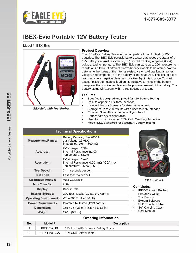
IBEX-Evic with Test Probes
Product OverviewThe IBEX-Evic Battery Tester is the complete solution for testing 12V batteries. The IBEX-Evic portable battery tester diagnoses the status of a 12V battery’s internal resistance (I.R.) or cold cranking amperes (CCA), voltage, and temperature. The IBEX-Evic can store up to 200 measurement results and allows 20 different alarms/battery models to be stored. Alarms determine the status of the internal resistance or cold cranking amperes, voltage, and temperature of the battery being measured. The included test leads include a negative clamp and positive 4-point test probe. To start testing, place the negative lead on the negative terminal of the battery then press the positive test lead on the positive terminal of the battery. The battery status will appear within three seconds of testing.
Features• Specifically designed and priced for 12V Battery Testing• Results appear in just three seconds• Included Evicom Software for data management• Storage of up to 200 results with a user-friendly interface• Compact Size - Fits in the palm of your hand• Battery data sheet generation• Used for ohmic testing or CCA (Cold Cranking Amperes)• Meets IEEE Standards for Stationary Battery Testing
Ordering InformationNo. Model # Description1 IBEX-Evic-IR 12V Internal Resistance Battery Tester2 IBEX-Evic-CCA 12V CCA Battery Tester
Technical Specifications
Measurement Range:Battery Capacity: 5 – 2000 AhJar Voltage: 12 VDCImpedance: 0.01 – 300 mΩ
Accuracy:DC Voltage: ±0.5%Internal Resistance: ±1.0%Temperature: ±2.0%
Resolution:DC Voltage: 10 mVInternal Resistance: 0.001 mΩ / CCA: 1 ATemperature: 0.5 °C (0.5 °F)
Test Speed: 3 – 4 seconds per cellTest Load: Less than 2A per cell
Calibration Method: Auto CalibrationData Transfer: USB
Display: Backlit LCDInternal Storage: 200 Test Results, 20 Battery Alarms
Operating Environment: -20 – 80 °C (-4 – 176 °F)Power Requirements Powered by tested (12V) battery
Dimensions 165 x 76 x 33 mm (6.5 x 3 x 1.3 in)Weight 270 g (9.5 oz)
Kit Includes• IBEX-Evic with Rubber
Protective Cover• Test Probes• Evicom Software• USB Transfer Cable• Soft Carrying Case• User Manual
IBEX-Evic Kit
13 www.eepowersolutions.com | toll free: 1-877-805-3377 | fax: 1-414-962-3660 | [email protected]
SG-Ultra Max Digital Hydrometer/Density MeterModel # SG-Ultra Max
SG-Ultra Max Kit
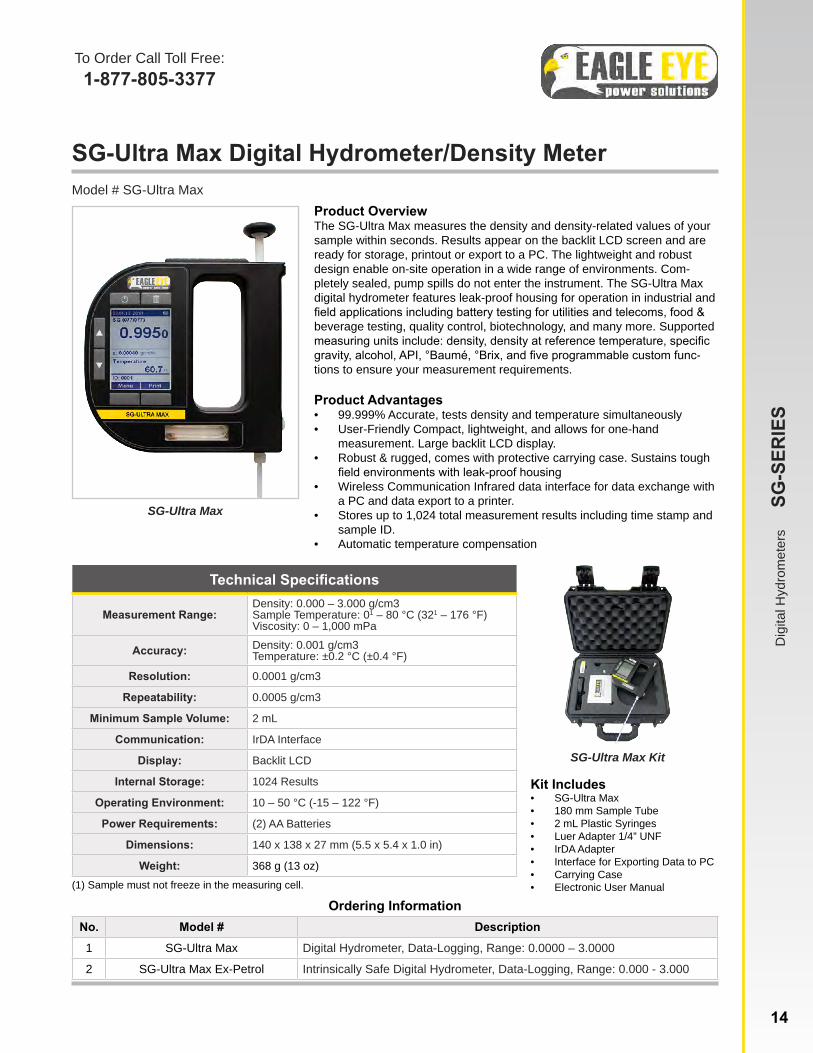
Product OverviewThe SG-Ultra Max measures the density and density-related values of your sample within seconds. Results appear on the backlit LCD screen and are ready for storage, printout or export to a PC. The lightweight and robust design enable on-site operation in a wide range of environments. Com-pletely sealed, pump spills do not enter the instrument. The SG-Ultra Max digital hydrometer features leak-proof housing for operation in industrial and field applications including battery testing for utilities and telecoms, food & beverage testing, quality control, biotechnology, and many more. Supported measuring units include: density, density at reference temperature, specific gravity, alcohol, API, °Baumé, °Brix, and five programmable custom func-tions to ensure your measurement requirements.
Product Advantages• 99.999% Accurate, tests density and temperature simultaneously• User-Friendly Compact, lightweight, and allows for one-hand
measurement. Large backlit LCD display.• Robust & rugged, comes with protective carrying case. Sustains tough
field environments with leak-proof housing• Wireless Communication Infrared data interface for data exchange with
a PC and data export to a printer.• Stores up to 1,024 total measurement results including time stamp and
sample ID.• Automatic temperature compensation
Ordering InformationNo. Model # Description
1 SG-Ultra Max Digital Hydrometer, Data-Logging, Range: 0.0000 – 3.0000
2 SG-Ultra Max Ex-Petrol Intrinsically Safe Digital Hydrometer, Data-Logging, Range: 0.000 - 3.000
Technical Specifications
Measurement Range:Density: 0.000 – 3.000 g/cm3Sample Temperature: 01 – 80 °C (321 – 176 °F)Viscosity: 0 – 1,000 mPa
Accuracy: Density: 0.001 g/cm3Temperature: ±0.2 °C (±0.4 °F)
Resolution: 0.0001 g/cm3
Repeatability: 0.0005 g/cm3
Minimum Sample Volume: 2 mL
Communication: IrDA Interface
Display: Backlit LCD
Internal Storage: 1024 Results
Operating Environment: 10 – 50 °C (-15 – 122 °F)
Power Requirements: (2) AA Batteries
Dimensions: 140 x 138 x 27 mm (5.5 x 5.4 x 1.0 in)
Weight: 368 g (13 oz)(1) Sample must not freeze in the measuring cell.
Kit Includes• SG-Ultra Max• 180 mm Sample Tube• 2 mL Plastic Syringes• Luer Adapter 1/4” UNF• IrDA Adapter • Interface for Exporting Data to PC• Carrying Case• Electronic User Manual
SG-Ultra Max
Dig
ital H
ydro
met
ers
SG
-SER
IES
14
To Order Call Toll Free:1-877-805-3377

SG-Ultra Digital Hydrometer/Density Meter
Dig
ital H
ydro
met
ers
SG
-SER
IES
To Order Call Toll Free:1-877-805-3377
Model # SG-Ultra
SG-Ultra Kit
Product OverviewThe SG-Ultra digital hydrometer/density meter offers 99.999% accurate, temperature-compensated specific gravity, density, and density-related values. Select from multiple units of measure to suit your measurement needs or create custom user-defined requirements. Results include sample identification, measurement unit, temperature correction coefficient, instrument identification and date & time. Results can be downloaded to a printer or PC easily. Reliable results appear in just 3 seconds - just immerse the sampling tube, pull the trigger, and read the final result. Trend results with included management software. The SG-Ultra is commonly used for battery testing (lead-acid & Ni-cad), alcohol and food testing, petroleum testing, and other custom density tests.
Advantages• Accurate 99.999% Accurate• User-Friendly Compact, lightweight, and allows for one-hand measurement.
Large LCD display screen with back-light• Robust & rugged, comes with protective carrying case. Sustains tough field
environments with a sealed housing• Wireless Communication Infrared data interface for data exchange with a PC
and data export to a printer (data transfer accessories included)• Storage of up to 1100 results including sample ID, measurement unit,
temperature correction coefficient, instrument identification, date and time• Reliable CE Compliant and One Year Warranty
Ordering InformationNo. Model # Description
1 SG-Ultra Digital Hydrometer, Data-Logging, Range: 0.0000 – 2.0000
Technical Specifications
Measurement Range:Density: 0.000 – 2.000 g/cm3Sample Temperature: 01 – 40 °C (321 – 104 °F)Viscosity: 0 – 2,000 mPa
Accuracy: Density: 0.001 g/cm3Temperature: ±0.2 °C (±0.4 °F)
Resolution: 0.0001 g/cm3
Minimum Sample Volume: 2 mL
Communication: IrDA Interface
Display: Backlit LCD
Internal Storage: 1100 Results
Operating Environment: 10 – 50 °C (-15 – 122 °F)
Power Requirements: (2) AAA Batteries
Dimensions: 229 x 114 x 64 mm (9 x 4.5 x 2.5 in)
Weight: 360 g (2.7 oz)
Sample Tube Dimensions: 178 x 3.175 mm / 7 x 1/8 in. Diameter*Custom lengths available
(1) Sample must not freeze in the measuring cell
Kit Includes• SG-Ultra with Protective Boot• (1) Sample Tube (7” x 1/8”)• IrDA Adapters• SG-Ultra Management Software• Carrying Case• User Manual
SG-Ultra
15

SG-1000 Digital Hydrometer / Specific Gravity Tester
Dig
ital H
ydro
met
ers
SG
-SER
IES
To Order Call Toll Free:1-877-805-3377
Model # SG-1000F or SG-1000CProduct OverviewThe SG-1000 digital hydrometer / specific gravity tester is specifically designed to quickly & safely measure the temperature-compensated specific gravity of your batteries. The SG-1000 is critical in determining the charge level of lead-acid batteries, without touching any liquid or cumbersome cleaning. Single-handed automatic operation makes this method 10x faster than conventional glass hydrometer and thermometer methods. Measure specific gravity and temperature simultaneously with a press of a button.
To measure battery electrolytes, simply extract a sample in your suction tube and press the “START” button. The temperature-compensated specific gravity is displayed on the screen. The user can select between the specific gravity reading and temperature reading by pressing the “SELECT” button. Measurement results are displayed in just three seconds.
Advantages• 99.998% Accurate• 10x faster than
conventional methods• Measure specific
gravity and temperature simultaneously
• Automatic temperature compensation
• Rugged & Durable• Digital display• CE Compliant• One Year Warranty
Ordering InformationNo. Model # Description
1 SG-1000F Battery Digital Hydrometer, Non-Datalogging, Range: 1.000 - 1.300, °F
2 SG-1000C Battery Digital Hydrometer, Non-Datalogging, Range: 1.000 - 1.300, °C
Technical Specifications
Measurement Range:Specific Gravity of Electrolyte: 0.000 – 1.300Sample Temperature: -10 – 50 °C (14 – 122 °F)
Accuracy: ±0.002 Specific Gravity
Resolution: 0.001 g/cm3
Display: Digital LCD
Operating Environment: 10 – 50 °C (-15 – 122 °F)
Power Requirements: 9V Battery
Dimensions: 70 x 40 x 210 mm (2.8 x 1.6 x 8.3 in)
Weight: 235 g (8 oz)
Kit Includes• SG-1000 Body• 9V Battery• Three (3) Sample Tubes• Hand Strap• Carrying Case• User Manual
SG-1000 Battery Digital Hydrometer
Applications• Telecom/Communications• Utilities• Mining• Government/Defense• Industrial Manufacturing• Motive Power• Battery Suppliers / Service Groups
SG-1000 Kit
16
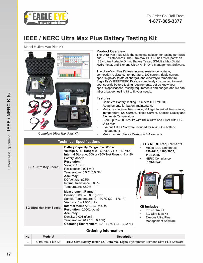
IEEE / NERC Ultra Max Plus Battery Testing KitModel # Ultra Max Plus-Kit
Product OverviewThe Ultra-Max Plus Kit is the complete solution for testing per IEEE and NERC standards. The Ultra-Max Plus Kit has three parts: an IBEX-Ultra Portable Ohmic Battery Tester, SG-Ultra Max Digital Hydrometer, and Exmons Ultra+ All-in-One Management Software.
The Ultra-Max Plus Kit tests internal resistance, voltage, connection resistance, temperature, DC current, ripple current, specific gravity (state of charge), and electrolyte temperature. Eagle Eye’s IEEE/NERC Kits are completely customized to meet your specific battery testing requirements. Let us know your specific applications, testing requirements and budget, and we can tailor a battery testing kit to fit your needs.
Features• Complete Battery Testing Kit meets IEEE/NERC
Requirements for battery maintenance• Measures: Internal Resistance, Voltage, Inter-Cell Resistance,
Temperature, DC Current, Ripple Current, Specific Gravity and Electrolyte Temperature
• Store up to 4,800 results with IBEX-Ultra and 1,024 with SG-Ultra Max
• Exmons Ultra+ Software included for All-in-One battery management
• Measures and Stores Results in 3-4 seconds
Ordering InformationNo. Model # Description
1 Ultra-Max-Plus Kit IBEX-Ultra Battery Tester, SG-Ultra Max Digital Hydrometer, Exmons Ultra Plus Software
Technical Specifications
IBEX-Ultra Key Specs:
Battery Capacity Range: 5 – 6000 AhVoltage & I.R. Range: 0 – 60 VDC / I.R. – 50 VDCInternal Storage: 600 or 4800 Test Results, 4 or 80 Battery ModelsResolution: Voltage: 10 mVResistance: 0.001 mΩTemperature: 0.5 C (0.5 °F)Accuracy:DC Voltage: ±0.5%Internal Resistance: ±0.5%Temperature: ±2.0%
SG-Ultra Max Key Specs:
Measurement Range:Density: 0.000 – 3.000 g/cm3Sample Temperature: *0 – 80 °C (32 – 176 °F)Viscosity: 0 – 1,000 mPaInternal Memory: 1024 ResultsResolution: 0.0001 g/cm3Accuracy:Density: 0.001 g/cm3Temperature: ±0.2 °C (±0.4 °F)Operating Environment: 10 – 50 °C (-15 – 122 °F)
Kit Includes• IBEX-Ultra Kit• SG-Ultra Max Kit• Exmons Ultra Plus
Management Software
Complete Ultra-Max-Plus Kit
IEEE / NERC Requirements• Meets IEEE Standards:
450-2010, 1188-2005, 1106-2005
• NERC Compliance: PRC-005-2
To Order Call Toll Free:1-877-805-3377
17
Batte
ry T
est E
quip
men
t I
EEE
/ NER
C K
its
www.eepowersolutions.com | toll free: 1-877-805-3377 | fax: 1-414-962-3660 | [email protected]
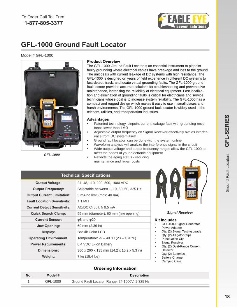
GFL-1000 Ground Fault LocatorModel # GFL-1000
GFL-1000
Product OverviewThe GFL-1000 Ground Fault Locator is an essential instrument to pinpoint faulty grounding where electrical cables have breakage and loss to the ground. The unit deals with current leakage of DC systems with high resistance. The GFL-1000 is designed on years of field experience in different DC systems to fast-detect, track, and locate virtual grounding faults. The GFL-1000 ground fault locator provides accurate solutions for troubleshooting and preventative maintenance, increasing the reliability of electrical equipment. Fast localiza-tion and elimination of grounding faults is critical for electricians and service technicians whose goal is to increase system reliability. The GFL-1000 has a compact and rugged design which makes it easy to use in small places and harsh environments. The GFL-1000 ground fault locator is widely used in the telecom, utilities, and transportation industries.
Advantages• Patented technology, pinpoint current leakage fault with grounding resis-
tance lower than 1MΩ• Adjustable output frequency on Signal Receiver effectively avoids interfer-
ence from DC system itself• Ground fault location can be done with the system online• Waveform analysis will analyze the interference signal in the circuit• Wide output voltage and output frequency ranges allow the GFL-1000 to
meet the needs of your electronic equipment• Reflects the aging status - reducing
maintenance and repair costs
Ordering InformationNo. Model # Description
1 GFL-1000 Ground Fault Locator, Range: 24-1000V, 1-325 Hz
Technical SpecificationsOutput Voltage: 24, 48, 110, 220, 500, 1000 VDC
Output Frequency: Selectable between 1, 10, 50, 60, 325 Hz
Output Current Limitation: 5 mA no limit (max: 40 mA)
Fault Location Sensitivity: ≤ 1 MΩ
Current Detect Sensitivity: AC/DC Circuit: ≥ 0.5 mA
Quick Search Clamp: 55 mm (diameter), 60 mm (jaw opening)
Current Sensor: φ8 and φ20
Jaw Opening: 60 mm (2.36 in)
Display: Backlit Color LCD
Operating Environment: Temperature: -5 – 40 °C (23 – 104 °F)
Power Requirements: 8.4 VDC Li-ion Battery
Dimensions: 360 x 260 x 135 mm (14.2 x 10.2 x 5.3 in)
Weight: 7 kg (15.4 lbs)
Kit Includes• GFL-1000 Signal Generator• Power Adapter• Qty. (2) Signal Testing Leads• Qty. (2) Alligator Clips• Punctuation Clip• Signal Receiver• Qty. (2) Dual-Range Current
Detector• Qty. (2) Batteries• Battery Charger• Carrying Case
Signal Receiver
To Order Call Toll Free:1-877-805-3377
www.eepowersolutions.com | toll free: 1-877-805-3377 | fax: 1-414-962-3660 | [email protected]
Gro
und
Faul
t Loc
ator
s
GFL
-SER
IES
18

SLB-Series DC Load BanksModel # SLB-Series
SLB-Series DC Load Bank
Product OverviewEagle Eye’s SMART Constant Current DC Load Banks are designed for discharge testing, battery capacity testing, acceptance testing, battery maintenance and other testing for DC power with a load. The SLB-Series load banks are portable, economic, easy-to-use and come complete with DataView Software for data management and analysis. The SMART technology allows a constant current discharge without the need for any adjustments during the test. With over 35 standard models, the SLB-Series is used in a variety of industries including utilities, telecommunications, UPS, motive power/forklifts, transportation, CATV, and many more. Custom Solutions are available. Eagle Eye load banks are designed to make discharge testing convenient and easy for any application.
Product Features• SMART Constant Current DC Load Banks with system and
cell voltage monitoring• Data management software included for data analyzing and
reporting• Rugged, compact and portable units• Alloy and PTC resistors for safe discharging• Four settings for auto shut-down of discharge: discharge time,
total string end voltage, cell end voltage, discharged capacity• Parallel connection of two units for mass discharge testing• Thermal cut-off and automatic overload protection• Safe circuits avoid damage to battery when testing• Optional: Real-time display of voltage for each cell with DAC
package for 1.2V, 2V, 6V, 12V cells• Optional: Custom DAC packages available for monitoring of
uncommon cell voltages and configurations
Data Acquisition Case (DAC)
DAC Connection to 48V Battery (2V) Cells
Data Acquisition Case (DAC):Eagle Eye’s SMART Load Banks come standard with monitoring of the system during discharge. An optional DAC package allows the voltage of EACH CELL to be wirelessly recorded and displayed during discharge. The DAC package allows the user to evaluate the health of each cell and replace only the cells that require replacement - saving time and money by significantly reducing labor hours and replacement costs.
To Order Call Toll Free:1-877-805-3377
SMAR
T D
C L
oad
Bank
s
SLB
-SER
IES
19
Typical connection of DAC’s to the battery cells include a test lead connected to each cell from the DAC. Each DAC can connect up to 12 cells. DAC’s are expandable to any size battery system and are compatible with VRLA, VLA, NiCad, and other battery types.
www.eepowersolutions.com | toll free: 1-877-805-3377 | fax: 1-414-962-3660 | [email protected]
Technical Specifications
Cell Voltage: Standard DAC: 1.2V1, 2V, 6V, 12V / Optional: Custom DAC configurations available upon request
Discharge Current Range: Single Load: 12 – 600A / Parallel Load: Up to 1200A
Discharge Voltage Range: Range: 10 – 576V (Max) / Voltage Steps: 12V, 24V, 36V, 48V, 80V, 125V, 240V, 380V, 480V
Accuracy: Discharge Current: 1% / Voltage: 0.5% – 0.8%
Resolution: Discharge Current: 0.1 A or 0.5% / Voltage: 0.001 V
Sampling Interval: 5 seconds – 1 minute
Data Transfer: USB, Wireless (466 MHz)
Display: Backlit LCD
Operating Environment: 0 – 40 °C (32 – 104 °F)
Power Requirements: 110/220 VAC 50/60 Hz / DC (from connected batteries)
Dimensions:
Small: 400 x 177 x 288 mm (15.7 x 7 x 11.3 in)Medium: 520 x 202 x 355 mm (20.5 x 8 x 14 in)Large: 555 x 225 x 435 mm (22.5 x 8.9 x 17.2 in)X-Large: 603 x 400 x 740 mm (23.7 x 15.7 x 29 in)XX-Large: 762 x 406 x 737 mm (30 x 16 x 29 in)
Weight:Small: 11 kg (24 lbs) Medium: 16 kg (36 lbs) Large: 21 kg (47 lbs) X-Large: 42 kg (93 lbs) XX-Large: 55 kg (122 lbs)
Safety Standard: CE Marked, EMC Standard(1)The standard DAC package includes quantity of DAC’s & cabling for 2V/6V/12V batteries; testing of 1.2V NiCad batteries require additional DAC & cabling. Please make sure to note testing of NiCad to your sales rep.
Ordering InformationNo. Model # Description
1 SLB-Series*SMART Constant Current DC Load Bank with Monitoring (12-480V, 100-600A)*See next page for listing of model numbers*Add “DAC” after model number for wireless monitoring per cell
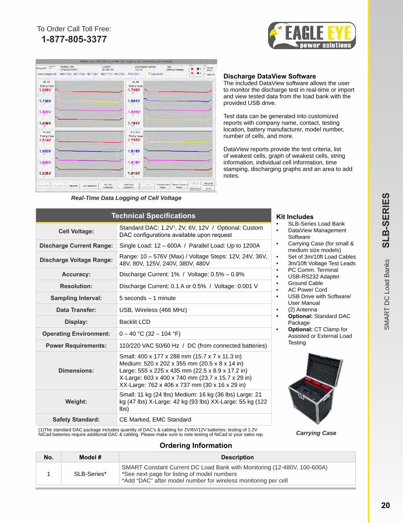
Discharge DataView SoftwareThe included DataView software allows the user to monitor the discharge test in real-time or import and view tested data from the load bank with the provided USB drive.
Test data can be generated into customized reports with company name, contact, testing location, battery manufacturer, model number, number of cells, and more.
DataView reports provide the test criteria, list of weakest cells, graph of weakest cells, string information, individual cell information, time stamping, discharging graphs and an area to add notes.
Kit Includes• SLB-Series Load Bank• DataView Management
Software• Carrying Case (for small &
medium size models)• Set of 3m/10ft Load Cables• 3m/10ft Voltage Test Leads• PC Comm. Terminal• USB-RS232 Adapter• Ground Cable• AC Power Cord• USB Drive with Software/
User Manual• (2) Antenna• Optional: Standard DAC
Package• Optional: CT Clamp for
Assisted or External Load Testing
Carrying Case
SMAR
T D
C L
oad
Bank
s
SLB
-SER
IES
20
To Order Call Toll Free:1-877-805-3377
www.eepowersolutions.com | toll free: 1-877-805-3377 | fax: 1-414-962-3660 | [email protected]
Real-Time Data Logging of Cell Voltage
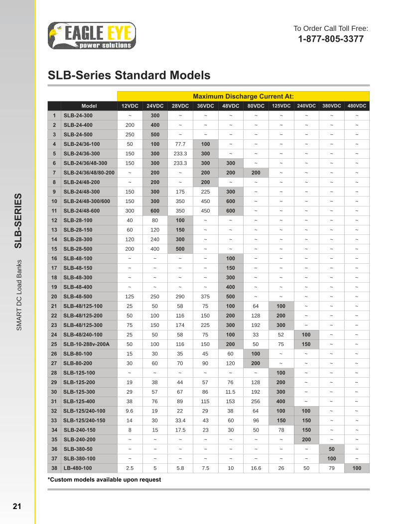
SLB-Series Standard Models
*Custom models available upon request
To Order Call Toll Free:1-877-805-3377
SMAR
T D
C L
oad
Bank
s
SLB
-SER
IES
Maximum Discharge Current At:Model 12VDC 24VDC 28VDC 36VDC 48VDC 80VDC 125VDC 240VDC 380VDC 480VDC
1 SLB-24-300 ~ 300 ~ ~ ~ ~ ~ ~ ~ ~
2 SLB-24-400 200 400 ~ ~ ~ ~ ~ ~ ~ ~
3 SLB-24-500 250 500 ~ ~ ~ ~ ~ ~ ~ ~
4 SLB-24/36-100 50 100 77.7 100 ~ ~ ~ ~ ~ ~
5 SLB-24/36-300 150 300 233.3 300 ~ ~ ~ ~ ~ ~
6 SLB-24/36/48-300 150 300 233.3 300 300 ~ ~ ~ ~ ~
7 SLB-24/36/48/80-200 ~ 200 ~ 200 200 200 ~ ~ ~ ~
8 SLB-24/48-200 ~ 200 ~ 200 ~ ~ ~ ~ ~ ~
9 SLB-24/48-300 150 300 175 225 300 ~ ~ ~ ~ ~
10 SLB-24/48-300/600 150 300 350 450 600 ~ ~ ~ ~ ~
11 SLB-24/48-600 300 600 350 450 600 ~ ~ ~ ~ ~
12 SLB-28-100 40 80 100 ~ ~ ~ ~ ~ ~ ~
13 SLB-28-150 60 120 150 ~ ~ ~ ~ ~ ~ ~
14 SLB-28-300 120 240 300 ~ ~ ~ ~ ~ ~ ~
15 SLB-28-500 200 400 500 ~ ~ ~ ~ ~ ~ ~
16 SLB-48-100 ~ ~ ~ ~ 100 ~ ~ ~ ~ ~
17 SLB-48-150 ~ ~ ~ ~ 150 ~ ~ ~ ~ ~
18 SLB-48-300 ~ ~ ~ ~ 300 ~ ~ ~ ~ ~
19 SLB-48-400 ~ ~ ~ ~ 400 ~ ~ ~ ~ ~
20 SLB-48-500 125 250 290 375 500 ~ ~ ~ ~ ~
21 SLB-48/125-100 25 50 58 75 100 64 100 ~ ~ ~
22 SLB-48/125-200 50 100 116 150 200 128 200 ~ ~ ~
23 SLB-48/125-300 75 150 174 225 300 192 300 ~ ~ ~
24 SLB-48/240-100 25 50 58 75 100 33 52 100 ~ ~
25 SLB-10-288v-200A 50 100 116 150 200 50 75 150 ~ ~
26 SLB-80-100 15 30 35 45 60 100 ~ ~ ~ ~
27 SLB-80-200 30 60 70 90 120 200 ~ ~ ~ ~
28 SLB-125-100 ~ ~ ~ ~ ~ ~ 100 ~ ~ ~
29 SLB-125-200 19 38 44 57 76 128 200 ~ ~ ~
30 SLB-125-300 29 57 67 86 11.5 192 300 ~ ~ ~
31 SLB-125-400 38 76 89 115 153 256 400 ~ ~ ~
32 SLB-125/240-100 9.6 19 22 29 38 64 100 100 ~ ~
33 SLB-125/240-150 14 30 33.4 43 60 96 150 150 ~ ~
34 SLB-240-150 8 15 17.5 23 30 50 78 150 ~ ~
35 SLB-240-200 ~ ~ ~ ~ ~ ~ ~ 200 ~ ~
36 SLB-380-50 ~ ~ ~ ~ ~ ~ ~ ~ 50 ~
37 SLB-380-100 ~ ~ ~ ~ ~ ~ ~ ~ 100 ~
38 LB-480-100 2.5 5 5.8 7.5 10 16.6 26 50 79 100
21 www.eepowersolutions.com | toll free: 1-877-805-3377 | fax: 1-414-962-3660 | [email protected]

LB-1000 Battery Charger / Discharger / ActivatorModel # LB-1000
LB-1000
Product OverviewThe LB-1000 is a complete solution for daily battery maintenance. It offers three complete solutions: battery charger, battery discharg-er and battery activator. All of these functions in one unit make the LB-1000 an important tool for any battery maintenance program. The battery charger, battery discharger, and battery activator options can be used individually or comprehensively. When the options are used comprehensively, lag-out battery will experience low-volt constant cur-rent charging and discharging of single or multi-cell batteries (1-99A). By activating the disabled active material of the battery electrode plate, it amends the battery malfunction caused by chemical failure and boosts the capacity of an old battery. Activation curve and certain parameters (e.g. voltage and resistance) will display on the screen as activation ends.
Features• Small size, portable and user-oriented• Applicable to single cell of 2V, 6V and 12V• 3 functions in one: charging, discharging, and activation (used
separately or comprehensively)• Testing waveform playback function• All-rounded and accurate testing results with vivid waveforms• Able to charge/discharge single and multi-cell batteries• Auto-sorting for lag-out batteries during discharging• Powerful Eagle Eye DataView Software for testing data, analyz-
ing, and report printing• Long-time monitoring of the battery condition• Safety circuits prevent damage to battery under test• Direct USB drive for data transferring to PC• Simple and fast for Software Updates• Helpful in restoring battery health
Ordering InformationNo. Model # Description
1 LB-1000 Battery Charger, Discharger, Activator
Technical Specifications
Charge/Discharge Current:
1-100A (cell: 2V) 1-30A (cell: 6V) 1-30A (cell: 12V) Accuracy: 1.0%Resolution: 1.0A
Total Charge/Discharge Voltage:
1.7-2.4V (2V) 5.4-7.2V (6V) 10.2-15V (12V) Accuracy: .25%Resolution: 0.1V
Display: Color LCDPower Requirements: AC 220V / 110V 50 / 60Hz
Dimensions: 394 x 368 x 198 mm (15.5 x 14.5 x 7.8 in)Weight: 10 kg (22 lbs)
Kit Includes• LB-1000 Main Unit• Voltage testing lead with (2)
clamps• Load Cables - Black and Red• AC Power Cord• LB-1000 Analyzing Software• Carrying Case• LB-1000 User Manual
Applications• Utilities• Transportation• UPS• Telecommunications• Service Groups
To Order Call Toll Free:1-877-805-3377
www.eepowersolutions.com | toll free: 1-877-805-3377 | fax: 1-414-962-3660 | [email protected]
Porta
ble
Load
Ban
ks
LB
-SER
IES
22
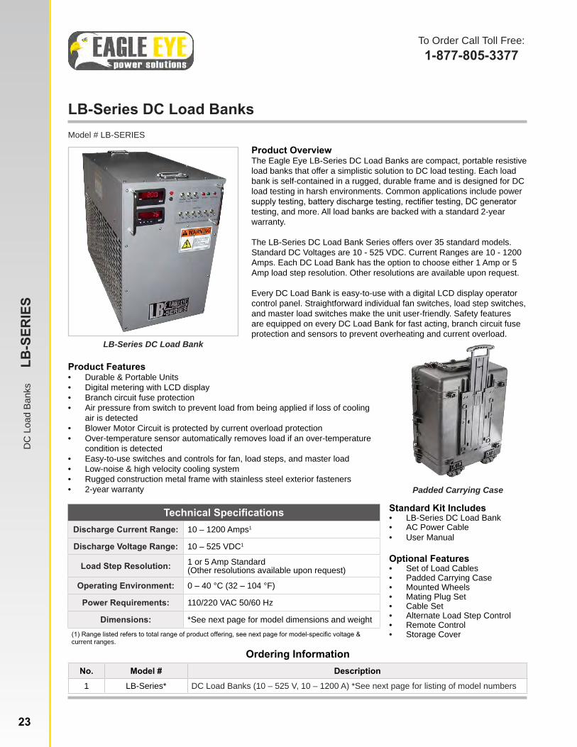
LB-Series DC Load BanksModel # LB-SERIES
LB-Series DC Load Bank
Product OverviewThe Eagle Eye LB-Series DC Load Banks are compact, portable resistive load banks that offer a simplistic solution to DC load testing. Each load bank is self-contained in a rugged, durable frame and is designed for DC load testing in harsh environments. Common applications include power supply testing, battery discharge testing, rectifier testing, DC generator testing, and more. All load banks are backed with a standard 2-year warranty.
The LB-Series DC Load Bank Series offers over 35 standard models. Standard DC Voltages are 10 - 525 VDC. Current Ranges are 10 - 1200 Amps. Each DC Load Bank has the option to choose either 1 Amp or 5 Amp load step resolution. Other resolutions are available upon request.
Every DC Load Bank is easy-to-use with a digital LCD display operator control panel. Straightforward individual fan switches, load step switches, and master load switches make the unit user-friendly. Safety features are equipped on every DC Load Bank for fast acting, branch circuit fuse protection and sensors to prevent overheating and current overload.
To Order Call Toll Free:1-877-805-3377
DC
Loa
d Ba
nks
LB
-SER
IES
23
Ordering InformationNo. Model # Description
1 LB-Series* DC Load Banks (10 – 525 V, 10 – 1200 A) *See next page for listing of model numbers
Technical SpecificationsDischarge Current Range: 10 – 1200 Amps1
Discharge Voltage Range: 10 – 525 VDC1
Load Step Resolution: 1 or 5 Amp Standard (Other resolutions available upon request)
Operating Environment: 0 – 40 °C (32 – 104 °F)
Power Requirements: 110/220 VAC 50/60 Hz
Dimensions: *See next page for model dimensions and weight(1) Range listed refers to total range of product offering, see next page for model-specific voltage & current ranges.
Standard Kit Includes• LB-Series DC Load Bank• AC Power Cable• User Manual
Optional Features • Set of Load Cables • Padded Carrying Case• Mounted Wheels• Mating Plug Set• Cable Set• Alternate Load Step Control• Remote Control• Storage Cover
Product Features• Durable & Portable Units• Digital metering with LCD display• Branch circuit fuse protection• Air pressure from switch to prevent load from being applied if loss of cooling
air is detected• Blower Motor Circuit is protected by current overload protection• Over-temperature sensor automatically removes load if an over-temperature
condition is detected• Easy-to-use switches and controls for fan, load steps, and master load• Low-noise & high velocity cooling system• Rugged construction metal frame with stainless steel exterior fasteners• 2-year warranty Padded Carrying Case

DC
Loa
d Ba
nks
LB
-SER
IES
24
Model No. Max. Discharge Current At: Dimensions Wgt.10-135VDC, 1A Res. 12V 24V 28V 36V 48V 80V 125V 240V 380V 480V L x W x H in. lbs.LB-12-300-1 300 ~ ~ ~ ~ ~ ~ ~ ~ ~ 16 x 12 x 12 25
LB-12/24/36/48-300-1 300 300 ~ 300 300 ~ ~ ~ ~ ~ 18 x 14 x 23 60
LB-24/48-300-1 48 300 56 13 300 ~ ~ ~ ~ ~ 18 x 14 x 23 50
LB-28-100-1 80 80 100 ~ ~ ~ ~ ~ ~ ~ 12 x 12 x 12 20
LB-48-300-1 160 160 187 120 300 ~ ~ ~ ~ ~ 18 x 14 x 23 40
LB-48/125-300-1 200 200 233 150 300 ~ ~ ~ ~ ~ 26 x 14 x 23 80
LB-125-100-1 320 320 373 240 320 267 100 ~ ~ ~ 18 x 14 x 23 40
LB-125-300-1 400 400 467 300 400 333 300 ~ ~ ~ 26 x 24 x 23 75
21-270VDC, 1A Res. 12V 24V 28V 36V 48V 80V 125V 240V 380V 480V L x W x H in. lbs.LB-21-270-1200-1 ~ 225 248 320 450 711 1200 600 ~ ~ 48 x 27 x 33 500
LB-21-270-900-1 ~ 175 111 240 350 533 900 450 ~ ~ 56 x 18 x 23 220
LB-21-270-600-1 ~ 110 74 160 225 356 600 300 ~ ~ 36 x 18 x 23 160
LB-21-270-300-1 ~ 50 37 80 120 178 300 150 ~ ~ 26 x 14 x 23 80
10-480VDC, 1A Res. 12V 24V 28V 36V 48V 80V 125V 240V 380V 480V L x W x H in. lbs.LB-10-480-60-1 48 48 56 36 48 40 60 60 48 60 27 x 14 x 23 60
LB-10-480-100-1 80 80 93 60 80 67 100 100 79 100 27 x 14 x 23 90
LB-10-480-200-1 160 160 187 120 160 133 200 200 158 200 36 x 18 x 23 160
LB-10-480-250-1 200 100 233 150 200 167 250 250 198 250 36 x 18 x 23 190
LB-10-480-400-1 320 320 373 240 320 267 400 400 317 400 56 x 18 x 23 250
LB-10-480-500-1 400 400 467 300 400 333 500 500 396 500 50 x 29 x 33 500
LB-480-500-1 12 24 28 31 48 66 125 250 396 500 50 x 29 x 33 450
10-135VDC, 5A Res. 12V 24V 28V 36V 48V 80V 125V 240V 380V 480V L x W x H in. lbs.LB-12-300-5 300 ~ ~ ~ ~ ~ ~ ~ ~ ~ 12 x 12 x 12 20
LB-12/24/36/48-300-5 300 300 233 300 300 ~ ~ ~ ~ ~ 18 x 14 x 23 55
LB-24/48-300-5 150 300 175 225 300 ~ ~ ~ ~ ~ 18 x 14 x 23 45
LB-28-100-5 43 86 100 ~ ~ ~ ~ ~ ~ ~ 12 x 12 x 12 15
LB-48-300-5 75 150 175 225 300 ~ ~ ~ ~ ~ 18 x 14 x 23 35
LB-48/125-300-5 75 150 175 225 300 200 300 ~ ~ ~ 26 x 14 x 23 75
LB-125-100-5 10 20 23 30 40 67 100 ~ ~ ~ 18 x 24 x 23 35
LB-125-300-5 30 60 70 90 120 200 300 ~ ~ ~ 26 x 14 x 23 60
21-270VDC, 5A Res. 12V 24V 28V 36V 48V 80V 125V 240V 380V 480V L x W x H in. lbs.LB-21-270-1200-5 ~ 225 300 175 450 300 1200 600 ~ ~ 56 x 18 x 23 220
LB-21-270-900-5 ~ 175 86 100 350 ~ 900 450 ~ ~ 36 x 18 x 23 160
LB-21-270-600-5 ~ 110 150 175 225 300 600 300 ~ ~ 23 x 14 x 23 80
LB-21-270-300-5 ~ 50 150 175 120 300 300 150 ~ ~ 26 x 14 x 23 60
10-480VDC, 5A Res. 12V 24V 28V 36V 48V 80V 125V 240V 380V 480V L x W x H in. lbs.LB-10-480-60-5 48 48 56 36 48 40 60 60 48 60 27 x 14 x 23 55
LB-10-480-100-5 80 80 93 60 80 67 100 100 79 100 27 x 14 x 23 70
LB-10-480-200-5 160 160 187 120 160 133 200 200 158 200 36 x 18 x 23 140
LB-10-480-250-5 200 200 233 150 200 167 250 250 198 250 36 x 18 x 23 170
LB-10-480-400-5 320 320 373 240 320 267 400 400 317 400 56 x 18 x 23 225
LB-10-480-500-5 400 400 467 300 400 333 500 500 396 500 50 x 29 x 33 500
LB-480-500-5 12 24 28 31 48 66 125 250 396 500 50 x 29 x 33 450
LB-Series Standard Models
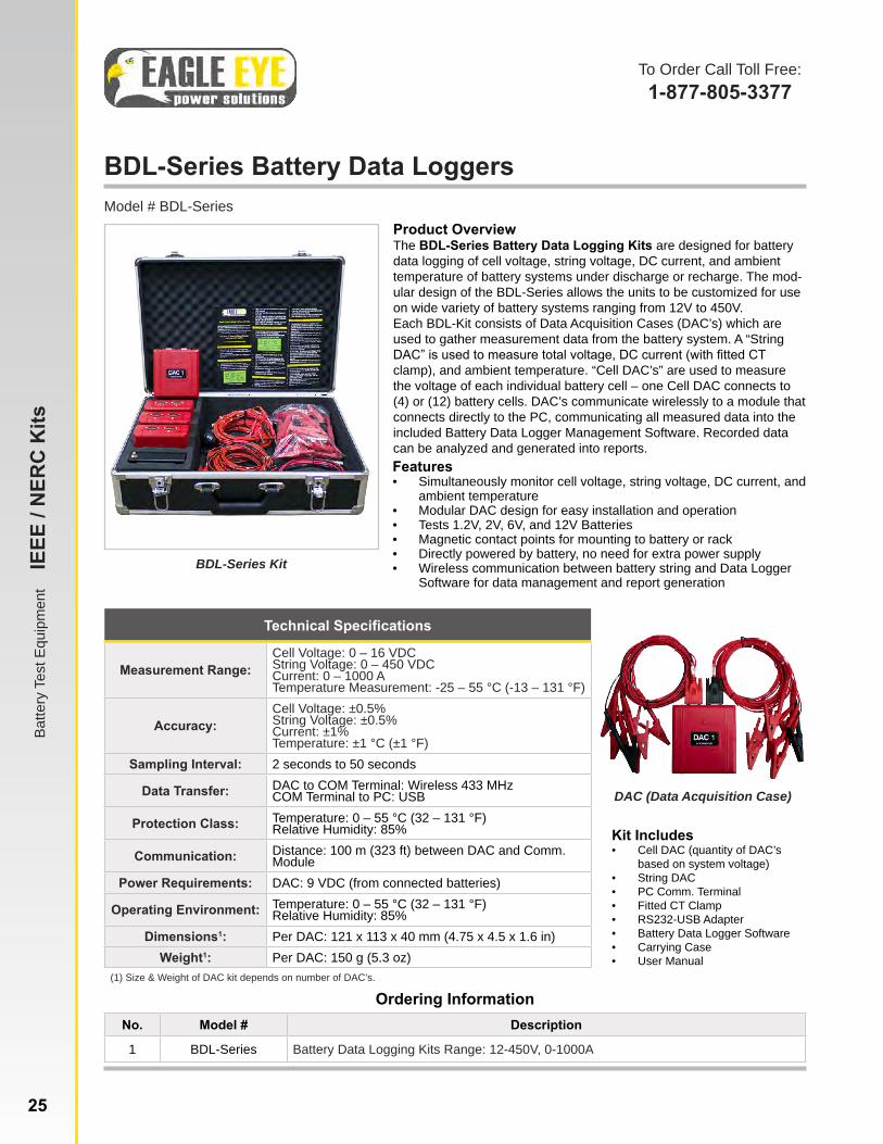
BDL-Series Battery Data LoggersModel # BDL-Series
BDL-Series Kit
Product OverviewThe BDL-Series Battery Data Logging Kits are designed for battery data logging of cell voltage, string voltage, DC current, and ambient temperature of battery systems under discharge or recharge. The mod-ular design of the BDL-Series allows the units to be customized for use on wide variety of battery systems ranging from 12V to 450V. Each BDL-Kit consists of Data Acquisition Cases (DAC’s) which are used to gather measurement data from the battery system. A “String DAC” is used to measure total voltage, DC current (with fitted CT clamp), and ambient temperature. “Cell DAC’s” are used to measure the voltage of each individual battery cell – one Cell DAC connects to (4) or (12) battery cells. DAC’s communicate wirelessly to a module that connects directly to the PC, communicating all measured data into the included Battery Data Logger Management Software. Recorded data can be analyzed and generated into reports. Features• Simultaneously monitor cell voltage, string voltage, DC current, and
ambient temperature• Modular DAC design for easy installation and operation• Tests 1.2V, 2V, 6V, and 12V Batteries• Magnetic contact points for mounting to battery or rack• Directly powered by battery, no need for extra power supply• Wireless communication between battery string and Data Logger
Software for data management and report generation
Ordering InformationNo. Model # Description
1 BDL-Series Battery Data Logging Kits Range: 12-450V, 0-1000A
Technical Specifications
Measurement Range:Cell Voltage: 0 – 16 VDCString Voltage: 0 – 450 VDCCurrent: 0 – 1000 ATemperature Measurement: -25 – 55 °C (-13 – 131 °F)
Accuracy:Cell Voltage: ±0.5%String Voltage: ±0.5%Current: ±1%Temperature: ±1 °C (±1 °F)
Sampling Interval: 2 seconds to 50 seconds
Data Transfer: DAC to COM Terminal: Wireless 433 MHzCOM Terminal to PC: USB
Protection Class: Temperature: 0 – 55 °C (32 – 131 °F)Relative Humidity: 85%
Communication: Distance: 100 m (323 ft) between DAC and Comm. Module
Power Requirements: DAC: 9 VDC (from connected batteries)
Operating Environment: Temperature: 0 – 55 °C (32 – 131 °F)Relative Humidity: 85%
Dimensions1: Per DAC: 121 x 113 x 40 mm (4.75 x 4.5 x 1.6 in)Weight1: Per DAC: 150 g (5.3 oz)
(1) Size & Weight of DAC kit depends on number of DAC’s.
Kit Includes• Cell DAC (quantity of DAC’s
based on system voltage)• String DAC• PC Comm. Terminal• Fitted CT Clamp• RS232-USB Adapter• Battery Data Logger Software• Carrying Case• User Manual
DAC (Data Acquisition Case)
Batte
ry D
ata
Logg
ing
B
DL-
SER
IES
www.eepowersolutions.com | toll free: 1-877-805-3377 | fax: 1-414-962-3660 | [email protected]
To Order Call Toll Free:1-877-805-3377
Batte
ry T
est E
quip
men
t I
EEE
/ NER
C K
its
25

LB-Series AC Load BanksModel # AC-LB-SERIES
Product OverviewThe AC Load Bank Series are the smallest AC load banks in the industry that offer unmatched capacities with rugged durability. Each load bank is fully self-contained and designed for portable AC load testing that can easily withstand harsh testing environments. Our patent-pending resistor design and assembly make it possible to achieve smaller portable load banks than anyone in the industry.
Every AC Load Bank is easy-to-use with a digital LCD display operator control panel. Straightforward individual fan switches, load step switches, and master load switches make the unit user-friendly. Safety features are equipped on every AC Load Bank for fast acting, branch circuit fuse protection and sensors to prevent overheating and current overload.
Product Features• Portable, lightweight, durable units
with powder coat finish metal frame & stainless steel exterior fasteners
• Digital metering with LCD display• Branch circuit fuse protection on all 3
phases of load steps• Air pressure switch to prevent load
from being applied if loss of cooling air is detected
• Temperature sensor removes load when over-temperature is detected
• Blower motor circuit is protected by current overload protection
• Easy-to-use switches & controls for fan, load steps & master load
• Low-noise, high velocity cooling system
• Standard 2 year warranty
Ordering InformationNo. Model # Description / Technical Specifications1 LB-30-208-3-1 30 kW at 208 VAC, 3 Phase, 50/60 Hz, 83.3 A per phase2 LB-60-208-3-5 60 kW at 208 VAC, 3 Phase, 50/60 Hz, 166.5 A per phase3 LB-80-208-3-5 80 kW at 208 VAC, 3 Phase, 50/60 Hz, 222 A per phase3 LB-100-208-3-5 100 kW at 208 VAC, 3 Phase, 120 VAC L-N, 60 Hz, 278 A per phase4 LB-100-240/480-3-5 100 kW at 240/480 VAC; 3 Phase, 120 VAC L-N, 60 Hz, 120/241 A per phase5 LB-100-MV-12.5 100 kW at 480 and 240 VAC, 3 Phase, 60 Hz, 120/241 A per phase6 LB-72-200-3-9-400 72 kW at 200 VAC, 3 Phase, 400 Hz, 115 V L-N, 208 A per phase7 LB-75-200-3-5-400 75 kW, 94 kVA at 200 VAC, 3 Phase, 400 Hz, 217 A per phase8 LB-100-200-3-5-400 100 kW, at 200 VAC, 3 Phase, 400 Hz, 289 A per phase9 LB-200-3-5-400 72 kW at 200 VAC, 3 Phase, 400 Hz, 115 V L-N, 208 A per phase10 LB-200-3-5-400 75 kW, 94 kVA at 200 VAC, 3 Phase, 400 Hz, 217 A per phase12 Custom Contact us to create a custom AC Load Bank solution
Kit Includes• AC Load Bank• Padded Carrying Case• Operation Manual• Optional: Set of Load Cables• Standard Models: 3-Line LCD
Display• 400Hz Models: 2-Line LCD Display• Optional: Shark LCD Display
(standard models only)• Optional: Mounted Wheels• Optional: VAC Control Power
AC Load Bank
Padded Carrying Case
Load Cables
To Order Call Toll Free:1-877-805-3377
AC L
oad
Bank
s
LB-S
ERIE
S
26

EnerGenius IQ Automatic DC Power Supply/Battery Charger
www.eepowersolutions.com | toll free: 877-805-3377 | fax: 414-962-3660 | [email protected]
Model # Energenius IQ
Energenius IQ, Size Q1 & Q2
Product DescriptionThe EnerGenius IQ Automatic DC Power Supply/Battery Charger delivers DC power and charges your battery system while testing battery performance, logging rel-evant site data, & communicating the results. Built-in intelligent control system reduces recharge time and cuts risk of overcharge, maximizing the reliability of DC systems at the lowest cost. The charger simultaneously supplies smooth DC to critical loads, re-charges the connected battery system, & automatically maintains VLA, VRLA, or NiCd batteries. Using Dynamic Equalize Charge, the charger automatically compensates for depth of discharge, varying load, battery age, & other variables.
Included standard on every EnerGenius IQ is an on-board battery check system to determine if your battery can support a connected continuous load without taking the battery offline or shutting down the charger. Black box data recorder captures and logs previously unavailable system and site data needed to analyze failures and demon-strate if site conditions are harming battery life. Dual microprocessors provide internal fault tolerance & provide a level of system reliability superior to either conventional analog or single microprocessor-controlled chargers.
Main Features• Built-in Intelligence makes it easy to correctly configure charger
for battery & site conditions• Battery Check System automatically tests battery to reduce risk
of expected application shutdown• Black Box Data Recorder helps spot previously hidden problems• Advanced User Interface, USB PC Utility provide easy to under-
stand system status & control• Dual Microprocessors, Digital Load Sharing minimize risk of
single point failure• Modbus Communication Option provides remote monitoring
Applications• Electric Utility Substations• Switchgear• Refineries & Chemical
Plants• DC Control Systems• Engine Starting• Oil & Gas Pipelines• Offshore Platforms
Ordering InformationModel Description
EnerGenius IQ Single Phase Batter Charger - See Order Form to build your custom model
Technical SpecificationsAC Input Voltage: 120/208/240 VAC, 60 Hz or 50/60Hz
DC Output Voltage: 12, 24, 48, 11/220 or 220/240 VDC nominal
Current Ratings: 6, 12, 16, 25, 35, 50 Amps
Voltage Regulation: +0.25%
Current Limit Adjust: 33% – 110% rated output
Operating Environment: -20 – 50 °C (-4 – 122 °F) Recommended
Agency Compliance: UL Listed
Dimensions1: Q1 Housing: 330 x 493 x 448 mm (13 x 19.4 x 17.6 in)Q2 Housing: 409 x 600 x 707 mm (16.1 x 23.6 x 27.08 in)
(1) Charger housing offered in two sizes, housing weight can vary based on specifications.
CommsGenius Communications Module allows data gathered by the charger to used to improve reliability of battery sites through the provided Insight PC-based application or their own networks. CommsGenius provides networking (RS-485 and Ethernet), precise digital load sharing for two chargers, and PC-based charger setup and administration.
EnerGenius Control Panel
To Order Call Toll Free:1-877-805-3377
Batte
ry T
est E
quip
men
t
Ener
geni
us IQ
27
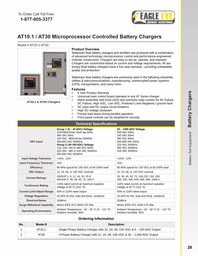
AT10.1 / AT30 Microprocessor Controlled Battery ChargersModel # AT10.1-AT30
Product OverviewStationary float battery chargers and rectifiers are produced with a combination of advanced technology microprocessor control and performance-engineered modular construction. Chargers are easy to set-up, operate, and maintain. Chargers are customized based on current and voltage requirements. All sta-tionary float battery chargers have a five year warranty - providing unbeatable quality and protection.
Stationary float battery chargers are commonly used in the following industries: utilities & telecommunications, manufacturing, uninterrupted power systems (UPS), transportation, and many more.
Features• 5 Year Product Warranty• Universal main control board operates in any AT Series charger• Alarm assembly with local LEDs and summary relay contact for AC Failure,
DC Failure, High VDC, Low VDC, Positive(+) and Negative(-) ground fault• AC input and DC output circuit breakers• High DC voltage shutdown• Forced load share during parallel operation• Front panel controls can be disabled for security
Ordering InformationNo. Model # Description
1 AT10.1 Single-Phase Battery Charger with 12, 24, 48, 130 VDC & 6 – 100 ADC Output
2 AT30 3-Phase Battery Charger with 12, 24, 48, 130 VDC & 25 – 1,000 ADC Output
Technical Specifications
VAC Input:
Group 1 (6 – 25 ADC) Voltage:120/208/240Vac Multi-tap 60Hz480 VAC 60Hz220 VAC, 380/416Vac 50/60Hz550-600 VAC 50/60HzGroup 2 (30-100 ADC) Voltage:120, 208, 240 or 480 VAC 60Hz220 VAC, 380 or 416 VAC 50/60Hz550-600 VAC 50/60Hz
25 – 1000 ADC Voltage:208 VAC 60Hz240 VAC 60Hz480 VAC 60Hz550-600 VAC 60Hz220 VAC 50/60Hz380 VAC 50/60Hz416 VAC 50/60Hz
Input Voltage Tolerance: +10%, -12% +10%, -12%
Input Frequency Tolerance: ±5% ±5%
Efficiency: 85-90% typical for 130 VDC at 50-100% load 85-90% typical for 130 VDC at 50-100% load
VDC Output: 12, 24, 48, or 130 VDC nominal 12, 24, 48, or 130 VDC nominal
Current Ratings: GROUP 1: 6, 12, 16, 20, 25 AGROUP 2: 30, 40, 50, 75, 100 A
25, 30, 40, 50, 75, 100,125, 150, 200,250, 300, 400, 500, 600, 800, 1000 A
Continuous Rating: 110% rated current at maximum equalizevoltage at 50 ºC (122 °F)
110% rated current at maximum equalizevoltage at 50 ºC (122 °F)
Current Limit Adjust Range: 50% to 110% rated output 50% to 110% rated output
Voltage Regulation: ±0.25% for line, load and temp. variations ±0.25% for line, load and temp. variations
Electrical Noise: 32dBrnc 32dBrnc
Surge Withstand Capability: Meets IEEE-472, ANSI C37.90a Meets IEEE-472, ANSI C37.90a
Operating Environment: Ambient Temperature: -18 – 50 °C (0 – 122 °F)Relative Humidity: 95%
Ambient Temperature: -18 – 50 °C (0 – 122 °F)Relative Humidity: 95%
AT10.1 & AT30 Chargers
www.eepowersolutions.com | toll free: 877-805-3377 | fax: 414-962-3660 | [email protected]
Batte
ry T
est E
quip
men
t B
atte
ry C
harg
ers
To Order Call Toll Free:1-877-805-3377
28

HGD-2000 Hydrogen Gas DetectorModel # HGD-2000
HGD-2000
Product OverviewThe HGD-2000 Hydrogen Gas Detector allows the user to monitor hydrogen gas buildup in storage rooms and facilities that house batteries or other industrial applications. Standard connections include single-phase AC power source and two internal relays that can be used to switch a remote exhaust fan and/or alarm on and off. If the concentration of hydrogen gas in the air surrounding the sensor reaches 1% by volume, a yellow LED will light and the 1% internal relay will close. A four second delay prevents false activation. If the concentration reaches 2%, a red LED will flash, the internal 80 db warning alarm will sound, and the 2% internal relay will close.
The optional HGVS-1000 Hydrogen Gas Ventilation System is a forced ventilation fan system that can be used in conjunction with the HGD-2000. It used in battery charging rooms and other areas where hydrogen may be present. The system has four fans factory-rated at 850 CFM each. The vents can be daisy chained; more than one vent can be controlled by one HGD-2000 gas detector and more than one HGD-2000 gas detector can activate a vent.
Features• Compliance with IEEE Std 450• Compliance with National Fire Protection Agency (NFPA) Article 64• Compliance with Uniform Building Code (UBC) Section 6400• Automatic Operation and Continuous 24/7 Monitoring• High Sensitivity and Stability• Save insurance costs - reduce insurance premiums when placed in battery
charging rooms
Ordering InformationNo. Model # Description1 HDG-2000 Hydrogen Gas Detector (Dual-Relay)2 Control Box Remote control box with connection cable3 HGVS-1000 Hydrogen Gas Ventilation System
Technical SpecificationsAlarm Relay: (2) form C contacts provided
Mounting: (4) 4.5 mm (3/16 in) screws
Operating Environment: Temperature: -10 – 40 °C (14 – 104 °F)
Power Requirements: 85 – 265 VAC, 50/60 Hz (standard)17 – 60 VDC (upon request)
Dimensions: 178 x 120 x 55 mm (7 x 4.75 x 2.5 in)
Kit Includes• HGD-2000• User Manual• Optional: Control Box and cable
for remote alarm control and display
• Optional: Junction Box• Optional: HGVS-1000 Hydrogen
Gas Ventilation System
(2) Form C Contacts
Control Box
Applications• Utilities and Power Plants• UPS Power Systems• Fuel Cell Test Stations• Nuclear Waste Reforming• Hydrogen Refueling Stations• Fire Department• Battery Suppliers• Battery Charging Rooms• Motive Power
To Order Call Toll Free:1-877-805-3377
Gas
Det
ectio
n
GD
-SER
IES
29 www.eepowersolutions.com | toll free: 877-805-3377 | fax: 414-962-3660 | [email protected]
HGVS-1000 Fan System
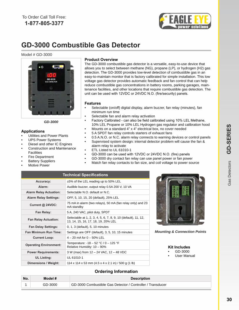
GD-3000 Combustible Gas Detector Model # GD-3000
Product OverviewThe GD-3000 combustible gas detector is a versatile, easy-to-use device that allows you to select between methane (NG), propane (LP), or hydrogen (H2) gas detection. The GD-3000 provides low-level detection of combustible gas in an easy-to-maintain monitor that is factory calibrated for simple installation. This low voltage gas detector provides automatic feedback and fan control that can help reduce combustible gas concentrations in battery rooms, parking garages, main-tenance facilities, and other locations that require combustible gas detection. The unit can be used with 12VDC or 24VDC N.O. (fire/security) panels.
Features• Selectable (on/off) digital display, alarm buzzer, fan relay (minutes), fan
minimum run time• Selectable fan and alarm relay activation• Factory Calibrated - can also be field calibrated using 10% LEL Methane,
10% LEL Propane or 10% LEL Hydrogen gas regulator and calibration hood• Mounts on a standard 4” x 4” electrical box, no cover needed• 5 A SPDT fan relay controls starters of exhaust fans• 0.5 A.N.O. or N.C. alarm relay connects to warning devices or control panels• Supervised system design: internal detector problem will cause the fan &
alarm relay to activate• ETL Listed to UL 61010-1• GD-3000 can be used with 12VDC or 24VDC N.O. (fire) panels• GD-3000 dry contact fan relay can use panel power or fan power• Match fan relay contacts to fan size, and coil voltage to power source
Ordering InformationNo. Model # Description
1 GD-3000 GD-3000 Combustible Gas Detector / Controller / Transducer
Technical SpecificationsAccuracy: ±5% of the LEL reading up to 50% LEL
Alarm: Audible buzzer, output relay 0.5A 200 V, 10 VA
Alarm Relay Actuation: Selectable N.O. default or N.C.
Alarm Relay Settings: OFF, 5, 10, 15, 20 (default), 25% LEL
Current @ 24VDC: 75 mA in alarm (two relays), 50 mA (fan relay only) and 23 mA standby
Fan Relay: 5 A, 240 VAC, pilot duty, SPDT
Fan Relay Actuation: Selectable at 1, 2, 3, 4, 5, 6, 7, 8, 9, 10 (default), 11, 12, 13, 14, 15, 16, 17, 18, 19, 20% LEL
Fan Delay Settings: 0, 1, 3 (default), 5, 10 minutes
Fan Minimum Run Time: Settings are OFF (default), 3, 5, 10, 15 minutes
Current Loop: 4 – 20 mA for 0 – 50% LEL
Operating Environment: Temperature: -18 – 52 °C / 0 – 125 °FRelative Humidity: 10 – 90%
Power Requirements: 3 W (max) from 12 – 24 VAC, 12 – 48 VDC
UL Listing: UL 61010-1
Dimensions / Weight: 114 x 114 x 53 mm (4.5 x 4 x 2.1 in) / 500 g (1 lb)
Kit Includes• GD-3000• User Manual
GD-3000
Applications• Utilities and Power Plants• UPS Power Systems• Diesel and other IC Engines• Construction and Maintenance
Facilities• Fire Department• Battery Suppliers• Motive Power
Mounting & Connection PointsG
as D
etec
tors
G
D-S
ERIE
S
30
To Order Call Toll Free:1-877-805-3377
www.eepowersolutions.com | toll free: 877-805-3377 | fax: 414-962-3660 | [email protected]
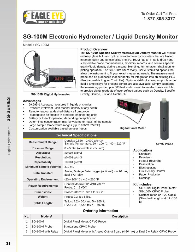
SG-100M Electronic Hydrometer / Liquid Density MonitorModel # SG-100M
Advantages• 99.995% Accurate, measures in liquids or slurries• Pressure irrelevant - can monitor density at any depth • Remote readout at desired distance from probe• Readout can be chosen in preferred engineering units• Battery or In-tank operation depending on application• Determines concentration mix (by volume or mass) of the sample• Large sample temperature ranges (up to 106°C / 220°F)• Customization available based on user needs
Ordering InformationNo. Model # Description
1 SG-100M Digital Panel Meter, CPVC Probe
2 SG-100M Probe Standalone CPVC Probe
3 SG-100M with Relay Digital Panel Meter with Analog Output Board (4-20 mA) or Dual 5 A Relay, CPVC Probe
Technical Specifications
Measurement Range: Density: 0.550 – 2.000 g/cm3*Sample Temperature: 20 – 106 °C / 40 – 220 °F
Pressure Range: 0 – 5 atm (operable in vacuum)Accuracy: ±0.005 g/cm3
Resolution: ±0.001 g/cm3Repeatability: ±0.004 g/cm3
Minimum Sample Volume: 310 mL
Data Transfer: Analog Voltage Data Logger (optional) 4 – 20 mA, dual 5 A Relay
Operating Environment: -20 – 106 °C / -40 – 220 °F
Power Requirements: Control Module: 120/240 VAC**Probe: 0 – 5 VDC
Dimensions: Probe: 280 x 51 mm / 11 x 2 in.Weight: Probe: 2.3 kg / 5 lbs.
Cable Length: Teflon: 1.2 – 30.4 m / 5 – 200 ft.PVC: 1.2 – 452.4 m / 4 – 500 ft.
Kit Includes:• SG-100M Digital Panel Meter• SG-100M CPVC Probe• Custom Teflon or PVC Cable
(Standard Lengths: 4 ft to 100 ft)
SG-100M Digital Hydrometer
Applications• Chemical• Petroleum• Food & Beverage• Passivation• Electroplating• Flux Density Control• Paper Production• Coatings
CPVC Probe
Digital Panel Meter
Product OverviewThe SG-100M Specific Gravity Meter/Liquid Density Monitor will replace ordinary glass bulb and optical refractometer hydrometers that are limited in range, utility and functionality. The SG-100M has an in-tank, drop-hang submersible probe that measures, monitors, records, and controls specific gravity/liquid density during a mixing, blending, fermentation, distillation, or plating operation. The SG-100M offers many user-customized options that allow the instrument to fit your exact measuring needs. The measurement probe can be purchased independently for integration into an existing PLC (Programmable Logger Controller). Optional 4-20mA analog output board or dual 5 amp relays for process control are also available. Simply submerge the measuring probe up to 500 feet and connect to an electronics module to provide digital readouts of user defined values such as Density, Specific Gravity, Baume, Brix and Alcohol %.
To Order Call Toll Free:1-877-805-3377
Dig
ital H
ydro
met
ers
SG
-SER
IES
31 www.eepowersolutions.com | toll free: 1-877-805-3377 | fax: 1-414-962-3660 | [email protected]
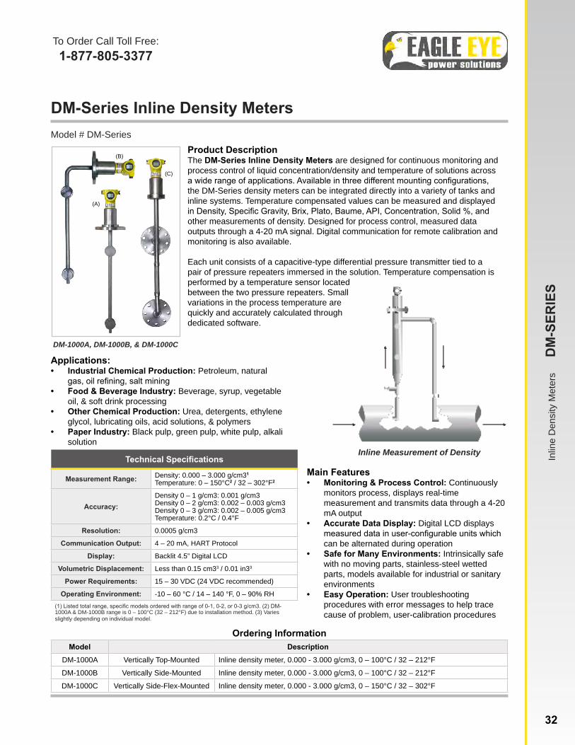
DM-Series Inline Density Meters Model # DM-Series
DM-1000A, DM-1000B, & DM-1000C
Product DescriptionThe DM-Series Inline Density Meters are designed for continuous monitoring and process control of liquid concentration/density and temperature of solutions across a wide range of applications. Available in three different mounting configurations, the DM-Series density meters can be integrated directly into a variety of tanks and inline systems. Temperature compensated values can be measured and displayed in Density, Specific Gravity, Brix, Plato, Baume, API, Concentration, Solid %, and other measurements of density. Designed for process control, measured data outputs through a 4-20 mA signal. Digital communication for remote calibration and monitoring is also available.
Each unit consists of a capacitive-type differential pressure transmitter tied to a pair of pressure repeaters immersed in the solution. Temperature compensation is performed by a temperature sensor located between the two pressure repeaters. Small variations in the process temperature are quickly and accurately calculated through dedicated software.
Main Features• Monitoring & Process Control: Continuously
monitors process, displays real-time measurement and transmits data through a 4-20 mA output
• Accurate Data Display: Digital LCD displays measured data in user-configurable units which can be alternated during operation
• Safe for Many Environments: Intrinsically safe with no moving parts, stainless-steel wetted parts, models available for industrial or sanitary environments
• Easy Operation: User troubleshooting procedures with error messages to help trace cause of problem, user-calibration procedures
Applications:• Industrial Chemical Production: Petroleum, natural
gas, oil refining, salt mining• Food & Beverage Industry: Beverage, syrup, vegetable
oil, & soft drink processing• Other Chemical Production: Urea, detergents, ethylene
glycol, lubricating oils, acid solutions, & polymers• Paper Industry: Black pulp, green pulp, white pulp, alkali
solution
Ordering InformationModel Description
DM-1000A Vertically Top-Mounted Inline density meter, 0.000 - 3.000 g/cm3, 0 – 100°C / 32 – 212°F
DM-1000B Vertically Side-Mounted Inline density meter, 0.000 - 3.000 g/cm3, 0 – 100°C / 32 – 212°F
DM-1000C Vertically Side-Flex-Mounted Inline density meter, 0.000 - 3.000 g/cm3, 0 – 150°C / 32 – 302°F
Technical Specifications
Measurement Range: Density: 0.000 – 3.000 g/cm31
Temperature: 0 – 150°C2 / 32 – 302°F2
Accuracy:Density 0 – 1 g/cm3: 0.001 g/cm3Density 0 – 2 g/cm3: 0.002 – 0.003 g/cm3Density 0 – 3 g/cm3: 0.002 – 0.005 g/cm3Temperature: 0.2°C / 0.4°F
Resolution: 0.0005 g/cm3
Communication Output: 4 – 20 mA, HART Protocol
Display: Backlit 4.5” Digital LCD
Volumetric Displacement: Less than 0.15 cm33 / 0.01 in33
Power Requirements: 15 – 30 VDC (24 VDC recommended)
Operating Environment: -10 – 60 °C / 14 – 140 °F, 0 – 90% RH(1) Listed total range, specific models ordered with range of 0-1, 0-2, or 0-3 g/cm3. (2) DM-1000A & DM-1000B range is 0 – 100°C (32 – 212°F) due to installation method. (3) Varies slightly depending on individual model.
Inline Measurement of Density
(A)
(B)
(C)
www.eepowersolutions.com | toll free: 1-877-805-3377 | fax: 1-414-962-3660 | [email protected]
To Order Call Toll Free:1-877-805-3377
Inlin
e D
ensi
ty M
eter
s
DM
-SER
IES
32
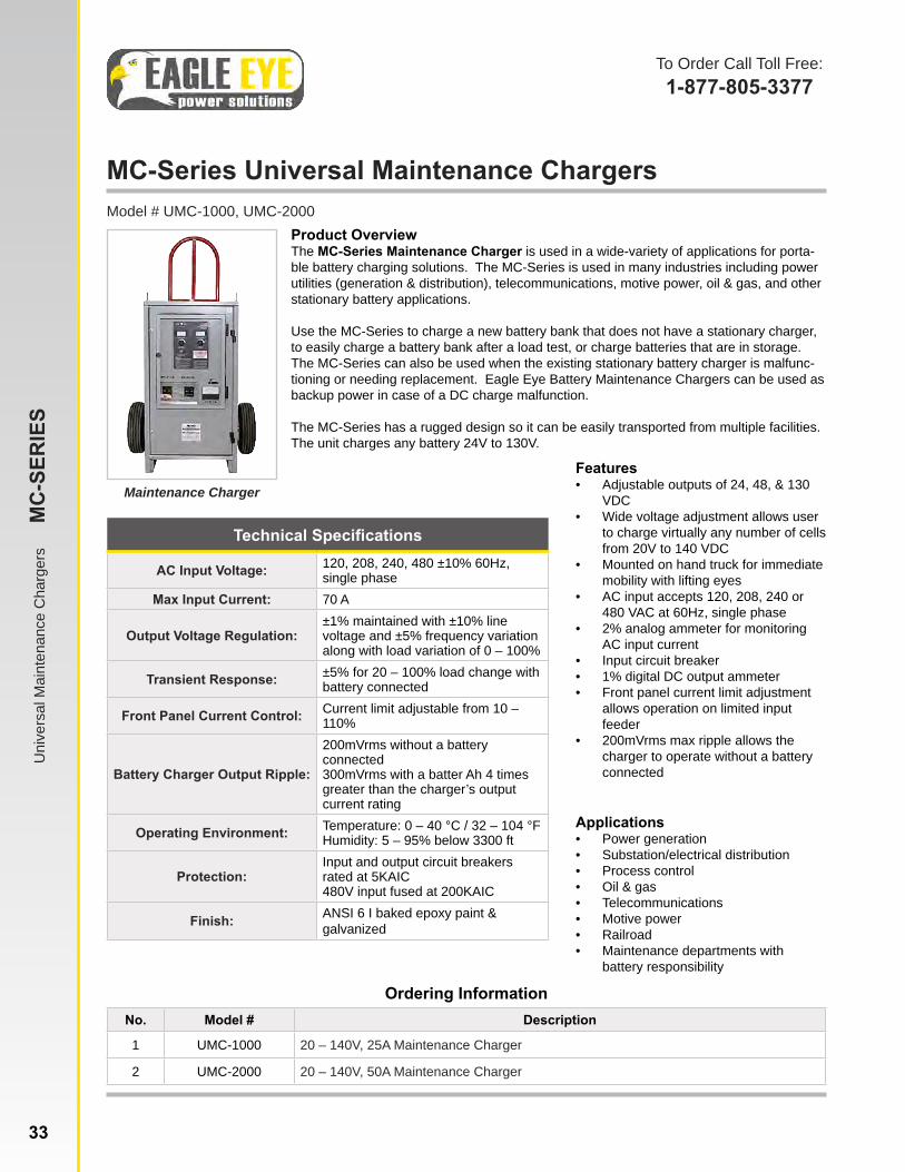
MC-Series Universal Maintenance ChargersModel # UMC-1000, UMC-2000
Maintenance Charger
Product OverviewThe MC-Series Maintenance Charger is used in a wide-variety of applications for porta-ble battery charging solutions. The MC-Series is used in many industries including power utilities (generation & distribution), telecommunications, motive power, oil & gas, and other stationary battery applications.
Use the MC-Series to charge a new battery bank that does not have a stationary charger, to easily charge a battery bank after a load test, or charge batteries that are in storage. The MC-Series can also be used when the existing stationary battery charger is malfunc-tioning or needing replacement. Eagle Eye Battery Maintenance Chargers can be used as backup power in case of a DC charge malfunction.
The MC-Series has a rugged design so it can be easily transported from multiple facilities. The unit charges any battery 24V to 130V.
Features• Adjustable outputs of 24, 48, & 130
VDC• Wide voltage adjustment allows user
to charge virtually any number of cells from 20V to 140 VDC
• Mounted on hand truck for immediate mobility with lifting eyes
• AC input accepts 120, 208, 240 or 480 VAC at 60Hz, single phase
• 2% analog ammeter for monitoring AC input current
• Input circuit breaker• 1% digital DC output ammeter• Front panel current limit adjustment
allows operation on limited input feeder
• 200mVrms max ripple allows the charger to operate without a battery connected
Ordering InformationNo. Model # Description
1 UMC-1000 20 – 140V, 25A Maintenance Charger
2 UMC-2000 20 – 140V, 50A Maintenance Charger
Technical Specifications
AC Input Voltage: 120, 208, 240, 480 ±10% 60Hz, single phase
Max Input Current: 70 A
Output Voltage Regulation:±1% maintained with ±10% line voltage and ±5% frequency variation along with load variation of 0 – 100%
Transient Response: ±5% for 20 – 100% load change with battery connected
Front Panel Current Control: Current limit adjustable from 10 – 110%
Battery Charger Output Ripple:
200mVrms without a battery connected300mVrms with a batter Ah 4 times greater than the charger’s output current rating
Operating Environment: Temperature: 0 – 40 °C / 32 – 104 °FHumidity: 5 – 95% below 3300 ft
Protection:Input and output circuit breakers rated at 5KAIC480V input fused at 200KAIC
Finish: ANSI 6 I baked epoxy paint & galvanized
Applications• Power generation• Substation/electrical distribution• Process control• Oil & gas• Telecommunications• Motive power• Railroad• Maintenance departments with
battery responsibility
To Order Call Toll Free:1-877-805-3377
Uni
vers
al M
aint
enan
ce C
harg
ers
M
C-S
ERIE
S
33 www.eepowersolutions.com | toll free: 1-877-805-3377 | fax: 1-414-962-3660 | [email protected]
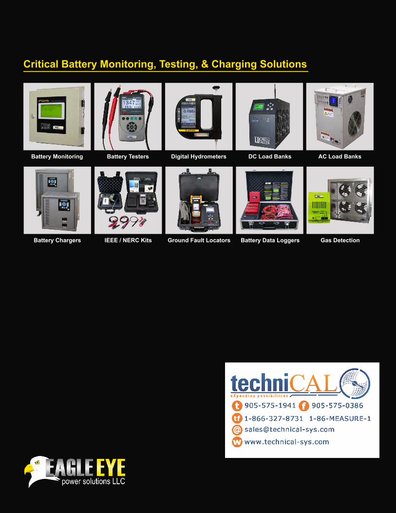
Battery Monitoring Battery Testers Digital Hydrometers DC Load Banks AC Load Banks
Battery Chargers IEEE / NERC Kits Ground Fault Locators Battery Data Loggers Gas Detection
Critical Battery Monitoring, Testing, & Charging Solutions