Embed Size (px)
Citation preview

Application Notes
Creating Printer Profiles with ColorGPS

Creating Printer Profiles with ColorGPS
Creating Printer Profiles with ColorGPS i
The ErgoSoft RIP is available in different editions. Therefore the description of available features in this document does not necessarily reflect the license details of your edition of the ErgoSoft RIP. For information on the features included in your edition of the ErgoSoft RIPs refer to the ErgoSoft homepage or contact your dealer.
Rev. 1.1
ErgoSoft AG Moosgrabenstr. 13 CH-8595 Altnau, Switzerland © 2010 ErgoSoft AG, All rights reserved. The information contained in this manual is based on information available at the time of publication and is sub-ject to change without notice. Accuracy and completeness are not warranted or guaranteed. No part of this manual may be reproduced or transmitted in any form or by any means, including electronic me-dium or machine-readable form, without the expressed written permission of ErgoSoft AG. Brand or product names are trademarks of their respective holders.

Creating Printer Profiles with ColorGPS ii
Contents
Basics on ColorGPS ................................................................................................................................................... 1 Using ColorGPS .......................................................................................................................................................... 2
Starting the ColorGPS Wizard ......................................................................................................................... 2 The ColorGPS Wizard ......................................................................................................................................... 2 Basic Settings ........................................................................................................................................................ 2
Choosing the Print Environment .............................................................................................................. 2 Creating the Profile ............................................................................................................................................. 3
Color Settings .................................................................................................................................................. 3 Total Ink Limit ...........................................................................................................................3 Black Generation .......................................................................................................................3
Calibration Chart Presets ............................................................................................................................ 3 Calibration Chart ............................................................................................................................................ 4
Printing the Calibration Chart ...................................................................................................4 Measuring the Calibration Chart...............................................................................................4
Calculating the Profile .................................................................................................................................. 6 Optional Settings ....................................................................................................................................................... 8
Overview of the Options ................................................................................................................................... 8 Using the Options................................................................................................................................................ 8
Calibration Chart ............................................................................................................................................ 8 ICC Neutral Black ........................................................................................................................................... 9 ICC Profile Accuracy ................................................................................................................................... 10 ICC Profile Contrast .................................................................................................................................... 10 ICC Profile Gamut Mapping .................................................................................................................... 11
Priorities ................................................................................................................................. 11 Color Purity ............................................................................................................................ 11 RGB Special ............................................................................................................................ 11 Color Gradients ...................................................................................................................... 12
ColorBoost Option ................................................................................................................................................. 12 Choosing the Correct GCR .................................................................................................................................. 13
No Black (GRC0) ................................................................................................................................................ 13 Black only in Shadows (GCR1) ..................................................................................................................... 13 Black in Dark Tones (GCR2)........................................................................................................................... 13 Black from middle Tones (GCR3) ................................................................................................................ 14 Black also in Light Tones (GCR4)................................................................................................................. 14 User defined Black (GCR+) ............................................................................................................................ 14
Creating Printer Profiles with ColorGPS 1
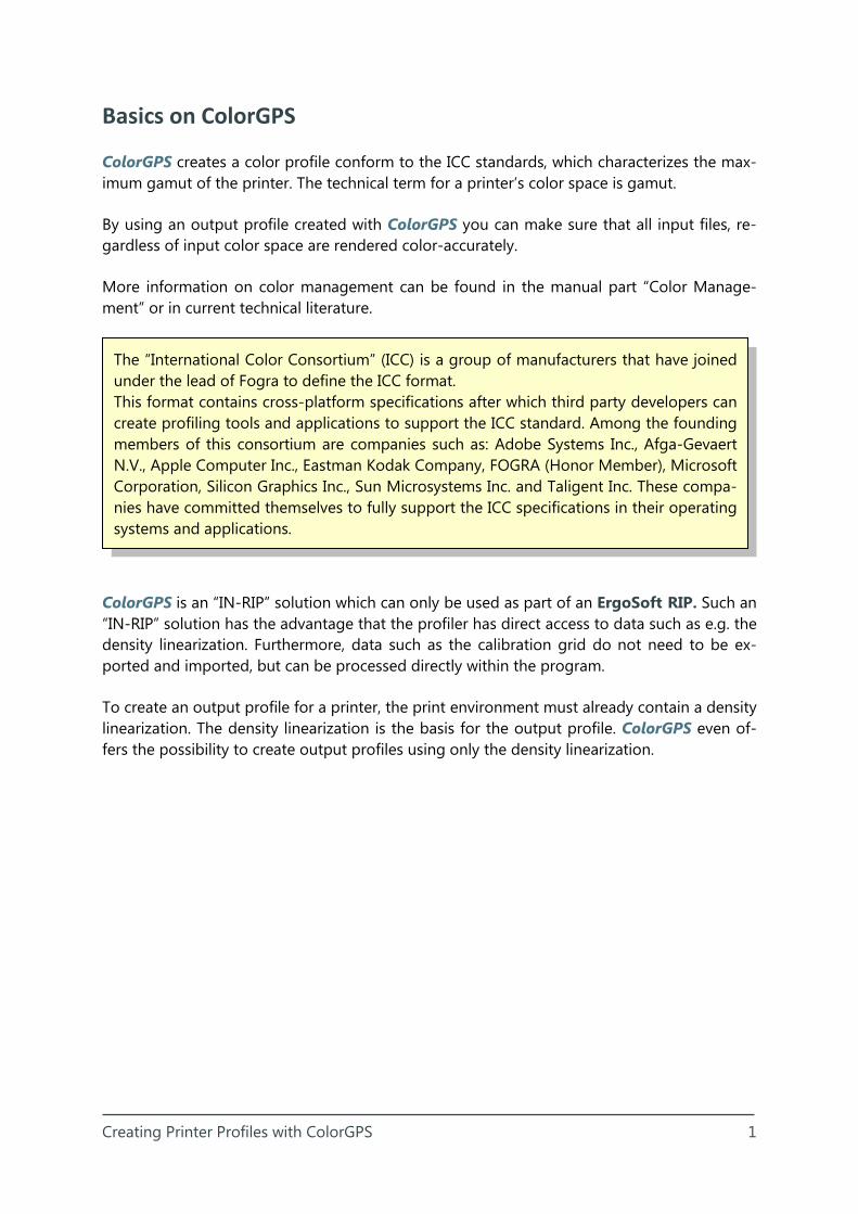
The “International Color Consortium” (ICC) is a group of manufacturers that have joined under the lead of Fogra to define the ICC format. This format contains cross-platform specifications after which third party developers can create profiling tools and applications to support the ICC standard. Among the founding members of this consortium are companies such as: Adobe Systems Inc., Afga-Gevaert N.V., Apple Computer Inc., Eastman Kodak Company, FOGRA (Honor Member), Microsoft Corporation, Silicon Graphics Inc., Sun Microsystems Inc. and Taligent Inc. These compa-nies have committed themselves to fully support the ICC specifications in their operating systems and applications.
Basics on ColorGPS
ColorGPS creates a color profile conform to the ICC standards, which characterizes the max-imum gamut of the printer. The technical term for a printer’s color space is gamut.
By using an output profile created with ColorGPS you can make sure that all input files, re-gardless of input color space are rendered color-accurately.
More information on color management can be found in the manual part “Color Manage-ment” or in current technical literature.
ColorGPS is an “IN-RIP” solution which can only be used as part of an ErgoSoft RIP. Such an “IN-RIP” solution has the advantage that the profiler has direct access to data such as e.g. the density linearization. Furthermore, data such as the calibration grid do not need to be ex-ported and imported, but can be processed directly within the program.
To create an output profile for a printer, the print environment must already contain a density linearization. The density linearization is the basis for the output profile. ColorGPS even of-fers the possibility to create output profiles using only the density linearization.
Creating Printer Profiles with ColorGPS 2
2
1
3
Using ColorGPS
Starting the ColorGPS Wizard
To start the wizard, click the ColorGPS icon under the Linearization & Profile Tools list in the Print Environment toolbar or select menu Tools > Linearization & Profile Tools > ColorGPS.
The ColorGPS Wizard
The ColorGPS Wizard is made up of two parts.
1. Basic settings Choosing the print environment
2. Creating the profile Color application Calibration chart Creating the profile
Basic Settings
Choosing the Print Environment
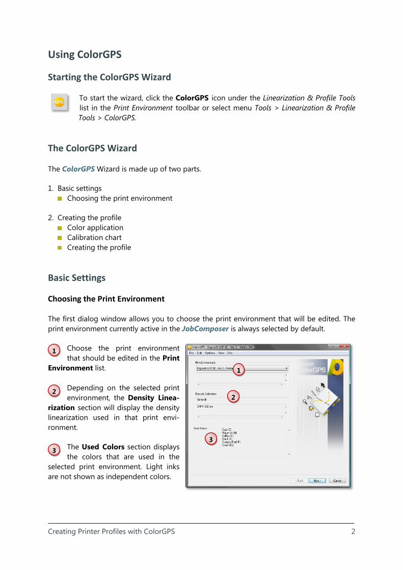
The first dialog window allows you to choose the print environment that will be edited. The print environment currently active in the JobComposer is always selected by default.
Choose the print environment that should be edited in the Print
Environment list.
Depending on the selected print environment, the Density Linea-
rization section will display the density linearization used in that print envi-ronment.
The Used Colors section displays the colors that are used in the
selected print environment. Light inks are not shown as independent colors.
1
2
3

Creating Printer Profiles with ColorGPS 3
1
2
Creating the Profile
Color Settings
The Color settings section allows you to set a maximum amount of
ink that should be used as well as how black inks (K) should be handled.
Total Ink Limit
The total ink limit for the profile is based on the total ink limit for CMYK files without input profile, which is de-fined in the print environment and adapted from there. But there is also a possibility to use different values.
Using the Apply Ink Limit on Top of Printer Profile option available in the print environment, the ink limit for the profile can be overwritten with the one from the print environment. Using a lower ink limit than the one the profile was created with can cause color inac-curacies. Hence this option should only be used in emergencies.
Black Generation
Using the dropdown menu Black Generation, the desired black generation can be selected. ColorGPS will recommend the most suitable black generation mode based on the set ink colors. You can find a more in-depth description of the different GCRs in the “Choosing the Correct GCR” section of this manual.
Calibration Chart Presets
In the dropdown menu Precision of the calibration chart, you can define how pre-cisely the printed chart should describe the gamut of the printer. A higher precision
leads to a higher amount of patches to be measured, but leads to better results.
Click the Calculate calibration chart button to create the calibration chart.
The Size of calibration chart section allows you to change the number of patches on the calculated calibration chart. This can be helpful if e.g. you need an exact amount of patches. An identical amount of patches combined with high precision of the calibration chart results in more accuracy on the gray axis while the combination with lower precision of the cali-bration chart results in more accuracy at the edges of the gamut.
1
2
3
5

Creating Printer Profiles with ColorGPS 4
3
4
Calibration Chart
Section Calibration chart allows printing and measuring the calibration chart as well as checking the measurements.
Printing the Calibration Chart
The generated calibration chart can now be printed using the Print button.
Measuring the Calibration Chart
Before starting to measure by using the Measure button, make sure that the Chart ID dis-played in the dialog matches the one printed on the chart. Now start the measuring dialog using the Measure button.
The Manage Measurements di-alog gives you an overview over the chart pages to be measured for the current calibration. The Meas-ured column shows how often a page has already been measured.
To measure a page, select it and start the measurement
with the Measure button. The upper part of the dialog shows which row should be measured next. Make sure that you always measure the line that is spe-cified.
The lower part of the dialog displays the progress of the measurement.
As soon as all lines of the current chart page have been measured, you can close the measuring dialog using the OK button.
4
3
4
Creating Printer Profiles with ColorGPS 5
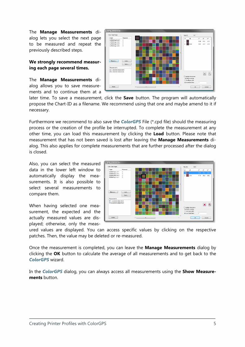
The Manage Measurements di-alog lets you select the next page to be measured and repeat the previously described steps.
We strongly recommend measur-ing each page several times.
The Manage Measurements di-alog allows you to save measure-ments and to continue them at a later time. To save a measurement, click the Save button. The program will automatically propose the Chart-ID as a filename. We recommend using that one and maybe amend to it if necessary.
Furthermore we recommend to also save the ColorGPS File (*.cpd file) should the measuring process or the creation of the profile be interrupted. To complete the measurement at any other time, you can load this measurement by clicking the Load button. Please note that measurement that has not been saved is lost after leaving the Manage Measurements di-alog. This also applies for complete measurements that are further processed after the dialog is closed.
Also, you can select the measured data in the lower left window to automatically display the mea-surements. It is also possible to select several measurements to compare them.
When having selected one mea-surement, the expected and the actually measured values are dis-played; otherwise, only the meas-ured values are displayed. You can access specific values by clicking on the respective patches. Then, the value may be deleted or re-measured.
Once the measurement is completed, you can leave the Manage Measurements dialog by clicking the OK button to calculate the average of all measurements and to get back to the ColorGPS wizard.
In the ColorGPS dialog, you can always access all measurements using the Show Measure-ments button.
Creating Printer Profiles with ColorGPS 6
5
Calculating the Profile
After having measured the calibration chart and closed the Measure Color Chart di-alog , click the Generate profile button to create the ICC profile. By default, the ICC
profile is automatically embedded into the current print environment. If the print environ-ment is configured to use an external printer profile (or when the ICC profile is re-created using saved ColorGPS data *.cpd and the original print environment does no longer exist) you are prompted to specify a name and save the ICC profile.
Please note that this will save the generated profile but not the settings and measurements used to create the profile. To save the settings (presets, calibration chart, measuring values, etc.) select menu File > Save. This will save all settings in a *.cpd file.
After having created the profile, close ColorGPS by clicking the Finish or the Cancel button. You will be prompted to save the ColorGPS data in a *.cpd file when not having saved them already.

Creating Printer Profiles with ColorGPS 7
COLORGPS
Optional Settings
Creating Printer Profiles with ColorGPS 8
1
2
3
Optional Settings
ColorGPS has several options available that allow the professional to make settings for ga-mut mapping and color mixing. These do however require technical knowledge to be used efficiently and precisely.
Overview of the Options
The ColorGPS menu bar allows selecting the following options. Depending on your license, some options might not be available to you.
Calibration Chart ICC Neutral Black ICC Profile Accuracy ICC Profile Contrast ICC Profile Gamut Mapping ICC Color Intensity (Color Boost)
Using the Options
Calibration Chart
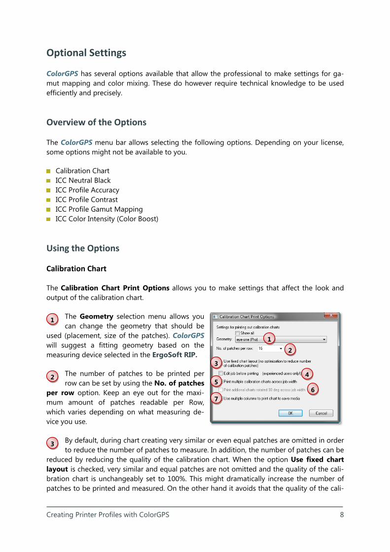
The Calibration Chart Print Options allows you to make settings that affect the look and output of the calibration chart.
The Geometry selection menu allows you can change the geometry that should be
used (placement, size of the patches). ColorGPS will suggest a fitting geometry based on the measuring device selected in the ErgoSoft RIP.
The number of patches to be printed per row can be set by using the No. of patches
per row option. Keep an eye out for the maxi-mum amount of patches readable per Row, which varies depending on what measuring de-vice you use.
By default, during chart creating very similar or even equal patches are omitted in order to reduce the number of patches to measure. In addition, the number of patches can be
reduced by reducing the quality of the calibration chart. When the option Use fixed chart layout is checked, very similar and equal patches are not omitted and the quality of the cali-bration chart is unchangeably set to 100%. This might dramatically increase the number of patches to be printed and measured. On the other hand it avoids that the quality of the cali-
1
2
3
4 5
6 7
Creating Printer Profiles with ColorGPS 9
4
5
6
7
bration chart is set to a too low value, especially when ColorGPS automatically creates small charts because of the number of inks used.
When using the Edit job before printing option, a generated chart can be edited in the ErgoSoft RIP just like every other. This option should only be used in special cases,
since the program will not automatically select the correct print environment; you will have to make sure the right one is selected yourself. Otherwise errors will occur during calibration.
Option Print multiple calibration charts across job width duplicates the calibration chart across the entire printing width, whereas every second chart is rotated by 180°.
This comes in handy at times since there are several charts available for ongoing processes (such as sublimation) or if a chart is damaged by e.g. printing errors, so you do not have to repeat the entire step.
If the option Print additional charts rotated 90° across job width is activated, a second row of calibration charts will be printed that is rotated by 90° respectively by
270°.
Instead of printing a long but small job with the calibration chart, option Use multiple columns to print chart to save media divides the long chart into several parts printed
next to each other in order to use the whole job width and thus, save media.
ICC Neutral Black
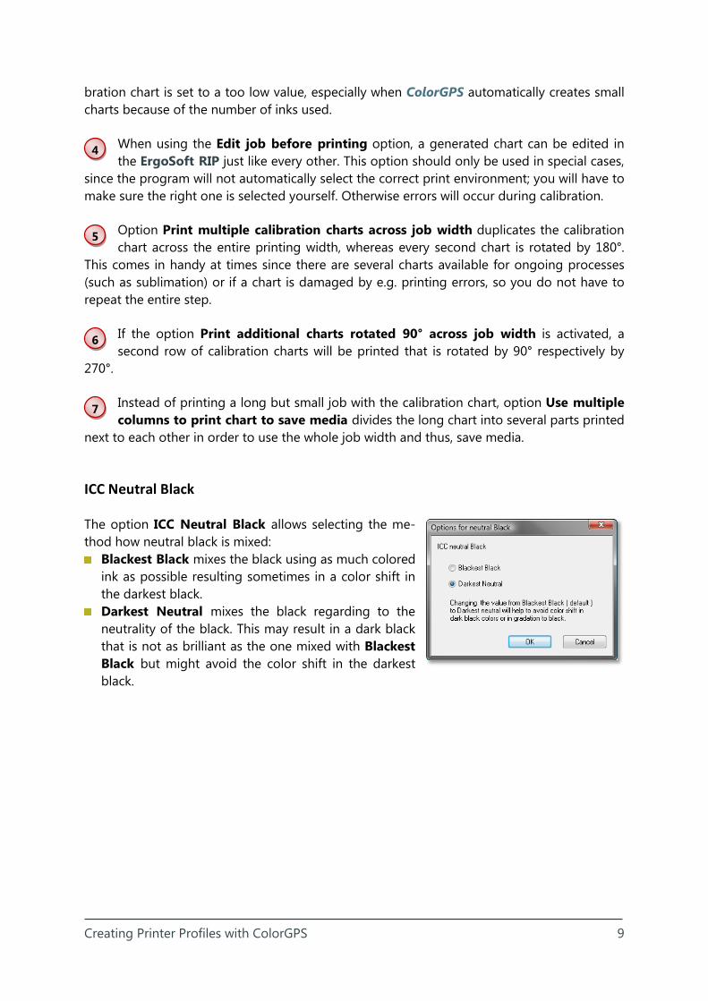
The option ICC Neutral Black allows selecting the me-thod how neutral black is mixed:
Blackest Black mixes the black using as much colored ink as possible resulting sometimes in a color shift in the darkest black.
Darkest Neutral mixes the black regarding to the neutrality of the black. This may result in a dark black that is not as brilliant as the one mixed with Blackest Black but might avoid the color shift in the darkest black.
Creating Printer Profiles with ColorGPS 10
ICC Profile Accuracy
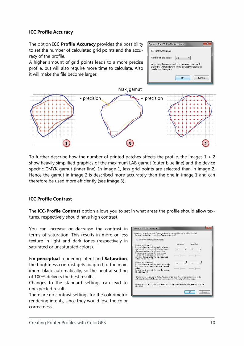
The option ICC Profile Accuracy provides the possibility to set the number of calculated grid points and the accu-racy of the profile. A higher amount of grid points leads to a more precise profile, but will also require more time to calculate. Also it will make the file become larger.
To further describe how the number of printed patches affects the profile, the images 1 + 2 show heavily simplified graphics of the maximum LAB gamut (outer blue line) and the device specific CMYK gamut (inner line). In image 1, less grid points are selected than in image 2. Hence the gamut in image 2 is described more accurately than the one in image 1 and can therefore be used more efficiently (see image 3).
ICC Profile Contrast
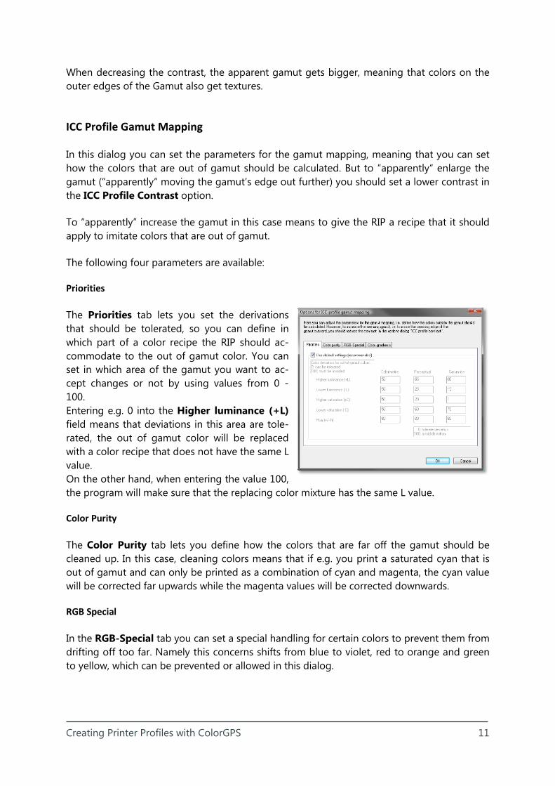
The ICC-Profile Contrast option allows you to set in what areas the profile should allow tex-tures, respectively should have high contrast.
You can increase or decrease the contrast in terms of saturation. This results in more or less texture in light and dark tones (respectively in saturated or unsaturated colors).
For perceptual rendering intent and Saturation, the brightness contrast gets adapted to the max-imum black automatically, so the neutral setting of 100% delivers the best results. Changes to the standard settings can lead to unexpected results. There are no contrast settings for the colorimetric rendering intents, since they would lose the color correctness.
- precision + precision
max. gamut
1 2 3
Creating Printer Profiles with ColorGPS 11
When decreasing the contrast, the apparent gamut gets bigger, meaning that colors on the outer edges of the Gamut also get textures.
ICC Profile Gamut Mapping
In this dialog you can set the parameters for the gamut mapping, meaning that you can set how the colors that are out of gamut should be calculated. But to “apparently“ enlarge the gamut (“apparently“ moving the gamut’s edge out further) you should set a lower contrast in the ICC Profile Contrast option.
To “apparently” increase the gamut in this case means to give the RIP a recipe that it should apply to imitate colors that are out of gamut.
The following four parameters are available:
Priorities
The Priorities tab lets you set the derivations that should be tolerated, so you can define in which part of a color recipe the RIP should ac-commodate to the out of gamut color. You can set in which area of the gamut you want to ac-cept changes or not by using values from 0 - 100. Entering e.g. 0 into the Higher luminance (+L) field means that deviations in this area are tole-rated, the out of gamut color will be replaced with a color recipe that does not have the same L value. On the other hand, when entering the value 100, the program will make sure that the replacing color mixture has the same L value.
Color Purity
The Color Purity tab lets you define how the colors that are far off the gamut should be cleaned up. In this case, cleaning colors means that if e.g. you print a saturated cyan that is out of gamut and can only be printed as a combination of cyan and magenta, the cyan value will be corrected far upwards while the magenta values will be corrected downwards.
RGB Special
In the RGB-Special tab you can set a special handling for certain colors to prevent them from drifting off too far. Namely this concerns shifts from blue to violet, red to orange and green to yellow, which can be prevented or allowed in this dialog.
Creating Printer Profiles with ColorGPS 12
Color Gradients
The Color Gradients tab is used to prevent so called “Graying” in gradients from dark satu-rated colors to black. As a bonus, other color gradients are automatically smoothed as well. However, with a low total ink limit (below 300%), setting a high value can also result in the contrary than what you hope to achieve.
ColorBoost Option
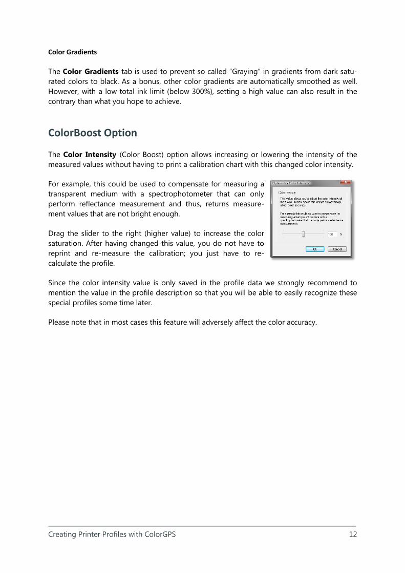
The Color Intensity (Color Boost) option allows increasing or lowering the intensity of the measured values without having to print a calibration chart with this changed color intensity.
For example, this could be used to compensate for measuring a transparent medium with a spectrophotometer that can only perform reflectance measurement and thus, returns measure-ment values that are not bright enough.
Drag the slider to the right (higher value) to increase the color saturation. After having changed this value, you do not have to reprint and re-measure the calibration; you just have to re-calculate the profile.
Since the color intensity value is only saved in the profile data we strongly recommend to mention the value in the profile description so that you will be able to easily recognize these special profiles some time later.
Please note that in most cases this feature will adversely affect the color accuracy.
Creating Printer Profiles with ColorGPS 13
25%
50%
75%
100%100%
75%
50%
25%
25%
50%
75%
100%100%
75%
50%
25%
25%
50%
75%
100%100%
75%
50%
25%
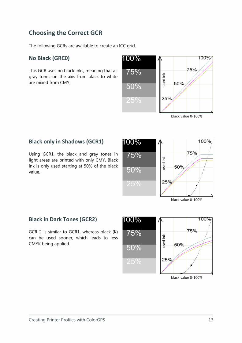
Choosing the Correct GCR
The following GCRs are available to create an ICC grid.
No Black (GRC0)
This GCR uses no black inks, meaning that all gray tones on the axis from black to white are mixed from CMY.
Black only in Shadows (GCR1)
Using GCR1, the black and gray tones in light areas are printed with only CMY. Black ink is only used starting at 50% of the black value.
Black in Dark Tones (GCR2)
GCR 2 is similar to GCR1, whereas black (K) can be used sooner, which leads to less CMYK being applied.
black value 0-100%
used
ink
used
ink
used
ink
black value 0-100%
black value 0-100%

Creating Printer Profiles with ColorGPS 14
25%
50%
75%
100%100%
75%
50%
25%
25%
50%
75%
100%100%
75%
50%
25%
Black from middle Tones (GCR3)
The middle GCR is a more extreme variant of GCR1 + 2. With this GCR, black inks can al-ready be used in middle tones.
Black also in Light Tones (GCR4)
GCR4 allows to print with maximal linear rising black from the beginning. At the end of the curve CMY is used to create a deep black.
User defined Black (GCR+)
GCR+ provides the possibility to define a custom black buildup, respectively setting up on your own how the black ink should be used.
Using the slider that can be moved between the values 0 and 100 the user can set from which brightness value be-tween paper white (0) and maximum black (100) the black ink should be used.
used
ink
used
ink
black value 0-100%
black value 0-100%