Embed Size (px)
Citation preview

Initials\S:\MAD\3600--3699\3626\007\BIDDING\ADDENDA\CRANE JONESBORO HVAC - ADDENDUM NO 1.DOCX
00900-1
ADDENDUM NO. 1
PROJECT MANUAL
HVAC COOLING PROJECT CONTRACT 3-2018
CRANE COMPOSITES, INC., JONESBORO, ARKANSAS Bids will be received until 2 P.M., local time, April 27, 2018. This Addendum to the Project Manual is issued to modify, explain, or correct the original Project Manual and is hereby made part of the Contract Documents. Insert the number of this Addendum in the blank space provided in the Bid, page 00400-2. A. GENERAL
1. See attached shop drawings for base bid fan coil units and air-cooled chiller.
B. SPECIFICATIONS
1. DIVISION 20–COMMON FIRE SUPPRESSION, PLUMBING, AND HVAC REQUIREMENTS
a. Page 20 07 16-1, SECTION 20 07 16–EQUIPMENT INSULATION FOR FIRE SUPPRESSION, PLUMBING, AND HVAC, PART 1–GENERAL, 1.01.A
REPLACE Corrosion protection system with “Wrap type fiberglass insulation.”
b. Page 20 07 16-3, SECTION 20 07 16–EQUIPMENT INSULATION FOR FIRE
SUPPRESSION, PLUMBING, AND HVAC, PART 2–PRODUCTS, 2.03.A, B, C, D, E ADD 2.03 WRAP TYPE FIBERGLASS INSULATION
A. Acceptable manufacturers are Johns Manville Microlite XG, Owens
Corning SOFTR, or Knauf Friendly Feel. B. Insulation shall be resin-bonded fiberglass type conforming to ASTM
C1290, Type 150. C. Minimum nominal density shall be 1.5 lbs./ft3. D. K-factor shall not exceed 0.25 (btu-in)/(hr-ft2-˚F) at 75˚F mean. E. Insulation shall be free of formaldehyde. F. Insulation jackets shall be PMJ. Jackets shall be in accordance with
Section 20 07 19 2.03.B. c. Page 20 07 16-4, SECTION 20 07 16–EQUIPMENT INSULATION FOR FIRE
SUPPRESSION, PLUMBING, AND HVAC, PART 3–PRODUCTS, 3.02.
REPLACE 3.02 CORROSION PROTECTION SYSTEM INSULATION section in its entirety with
“3.02 WRAP TYPE FIBERGLASS INSULATION INSTALLATION.
Initials\S:\MAD\3600--3699\3626\007\BIDDING\ADDENDA\CRANE JONESBORO HVAC - ADDENDUM NO 1.DOCX
00900-2
A. Insulation shall be installed per manufacturer’s recommendations with mechanical fasteners. Seal all joints and fasteners with UL-labeled vapor-proof tape.
B. Provide finished edges at all access doors and ends.”
d. Page 20 07 16-4, SECTION 20 07 16–EQUIPMENT INSULATION FOR FIRE
SUPPRESSION, PLUMBING, AND HVAC, PART 3–PRODUCTS, 3.03.B
ADD Mezzanine Supply Ductwork, Wrap Type Fiberglass Insulation, PMJ Jacket, 1.0” to table.
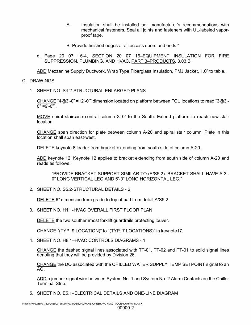
C. DRAWINGS 1. SHEET NO. S4.2-STRUCTURAL ENLARGED PLANS
CHANGE “4@3’-0” =12’-0”” dimension located on platform between FCU locations to read “3@3’-0” =9’-0””.
MOVE spiral staircase central column 3’-0” to the South. Extend platform to reach new stair location. CHANGE span direction for plate between column A-20 and spiral stair column. Plate in this location shall span east-west. DELETE keynote 8 leader from bracket extending from south side of column A-20. ADD keynote 12. Keynote 12 applies to bracket extending from south side of column A-20 and reads as follows:
“PROVIDE BRACKET SUPPORT SIMILAR TO (E/S5.2). BRACKET SHALL HAVE A 3’-0” LONG VERTICAL LEG AND 6’-0” LONG HORIZONTAL LEG.”
2. SHEET NO. S5.2-STRUCTURAL DETAILS - 2
DELETE 6” dimension from grade to top of pad from detail A/S5.2
3. SHEET NO. H1.1-HVAC OVERALL FIRST FLOOR PLAN
DELETE the two southernmost forklift guardrails protecting louver.
CHANGE “(TYP. 9 LOCATION)” to “(TYP. 7 LOCATIONS)” in keynote17.
4. SHEET NO. H8.1–HVAC CONTROLS DIAGRAMS - 1
CHANGE the dashed signal lines associated with TT-01, TT-02 and PT-01 to solid signal lines denoting that they will be provided by Division 26. CHANGE the DO associated with the CHILLED WATER SUPPLY TEMP SETPOINT signal to an AO. ADD a jumper signal wire between System No. 1 and System No. 2 Alarm Contacts on the Chiller Terminal Strip.
5. SHEET NO. E5.1–ELECTRICAL DETAILS AND ONE-LINE DIAGRAM
Initials\S:\MAD\3600--3699\3626\007\BIDDING\ADDENDA\CRANE JONESBORO HVAC - ADDENDUM NO 1.DOCX
00900-3
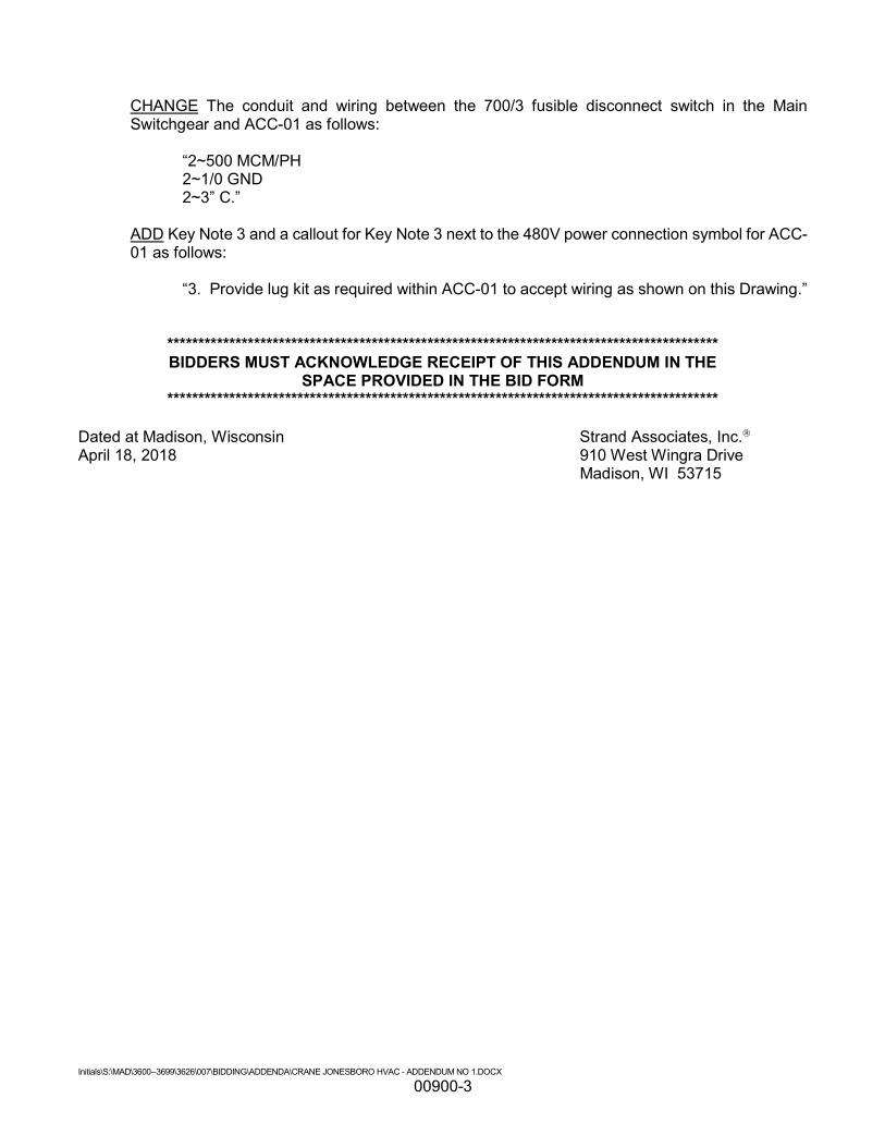
CHANGE The conduit and wiring between the 700/3 fusible disconnect switch in the Main Switchgear and ACC-01 as follows:
“2~500 MCM/PH 2~1/0 GND 2~3” C.”
ADD Key Note 3 and a callout for Key Note 3 next to the 480V power connection symbol for ACC-01 as follows:
“3. Provide lug kit as required within ACC-01 to accept wiring as shown on this Drawing.”
***************************************************************************************** BIDDERS MUST ACKNOWLEDGE RECEIPT OF THIS ADDENDUM IN THE
SPACE PROVIDED IN THE BID FORM *****************************************************************************************
Dated at Madison, Wisconsin Strand Associates, Inc. April 18, 2018 910 West Wingra Drive Madison, WI 53715
SUBMITTAL PRIVILEGE AND CONFIDENTIALITY NOTICE: The information contained in this message is proprietary and confidential under applicable law, and is intended only for the use of the individual or entity named.
Date: 4.4.18
Purchaser: Strand Job Name: Crane Composites
Address:
Engineer: Strand
Phone: Glacier Project #: 16237
Fax:
WWW.THEGLACIERGROUP.NET
1001 Fourier Drive | Suite 202 | Madison WI 53717
P. 608-830-5210 | F.608-830-5215
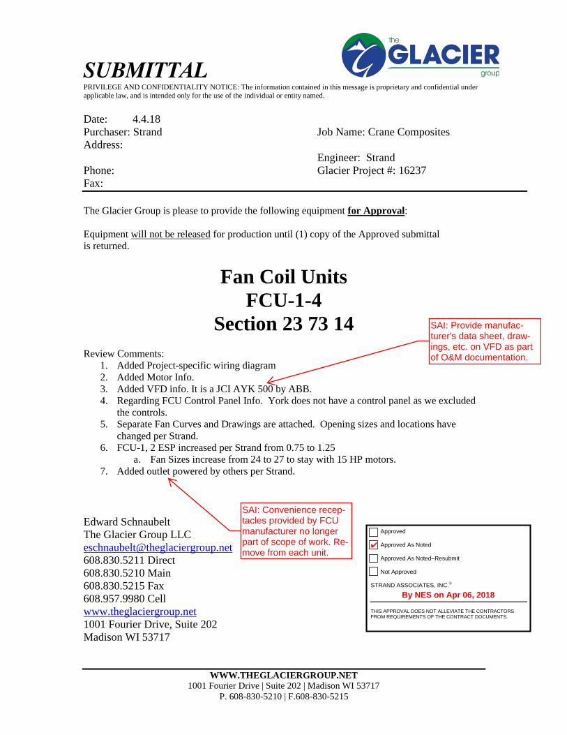
The Glacier Group is please to provide the following equipment for Approval:
Equipment will not be released for production until (1) copy of the Approved submittal
is returned.
Fan Coil Units
FCU-1-4
Section 23 73 14 Review Comments:
1. Added Project-specific wiring diagram
2. Added Motor Info.
3. Added VFD info. It is a JCI AYK 500 by ABB.
4. Regarding FCU Control Panel Info. York does not have a control panel as we excluded
the controls.
5. Separate Fan Curves and Drawings are attached. Opening sizes and locations have
changed per Strand.
6. FCU-1, 2 ESP increased per Strand from 0.75 to 1.25
a. Fan Sizes increase from 24 to 27 to stay with 15 HP motors.
7. Added outlet powered by others per Strand.
Edward Schnaubelt
The Glacier Group LLC
608.830.5211 Direct
608.830.5210 Main
608.830.5215 Fax
608.957.9980 Cell
www.theglaciergroup.net
1001 Fourier Drive, Suite 202
Madison WI 53717
SAI: Convenience recep-tacles provided by FCU manufacturer no longer part of scope of work. Re-move from each unit.
SAI: Provide manufac-turer's data sheet, draw-ings, etc. on VFD as part of O&M documentation.
Approved Approved As Noted Approved As Noted–Resubmit Not Approved
STRAND ASSOCIATES, INC.
THIS APPROVAL DOES NOT ALLEVIATE THE CONTRACTORS FROM REQUIREMENTS OF THE CONTRACT DOCUMENTS.
✔
By NES on Apr 06, 2018

WWW.THEGLACIERGROUP.NET
1001 Fourier Drive | Suite 202 | Madison WI 53717
P. 608-830-5210 | F.608-830-5215
SOLUTION AIR-HANDLING UNIT(S) (Build Time 6 weeks) TAG: FCU-1, 2, 3, 4
(4) YORK Solution indoor air-handling unit(s) complete with:
16,000 CFM
6 inch base
Double wall construction with 1% Leakage and 1/240 Deflection design at +/- 8 inches SP
18g Exterior Panels per spec
16g Interior Panels per spec
Flat Filter Section as specified
- 2''-30% efficient pleated filters - Filter gauges - Spare set of filters
Cooling Coil Section with stainless steel drain pan o Flat Fins
Access – Left Hand
Plenum Supply Fan o Unit mounted VFDs o 15 HP o Shaft Ring o TEFC Motors o Nema1 Enclosure for Indoor Units o Non-Fused Disconnect
5 year parts warranty
Training
Freight FOB Jobsite ($500 per unit has been added to this line already for this)
ITEMS NOT INCLUDED
Controls and control valves

SOLUTION XT AIR HANDLING UNITPERFORMANCE SPECIFICATION
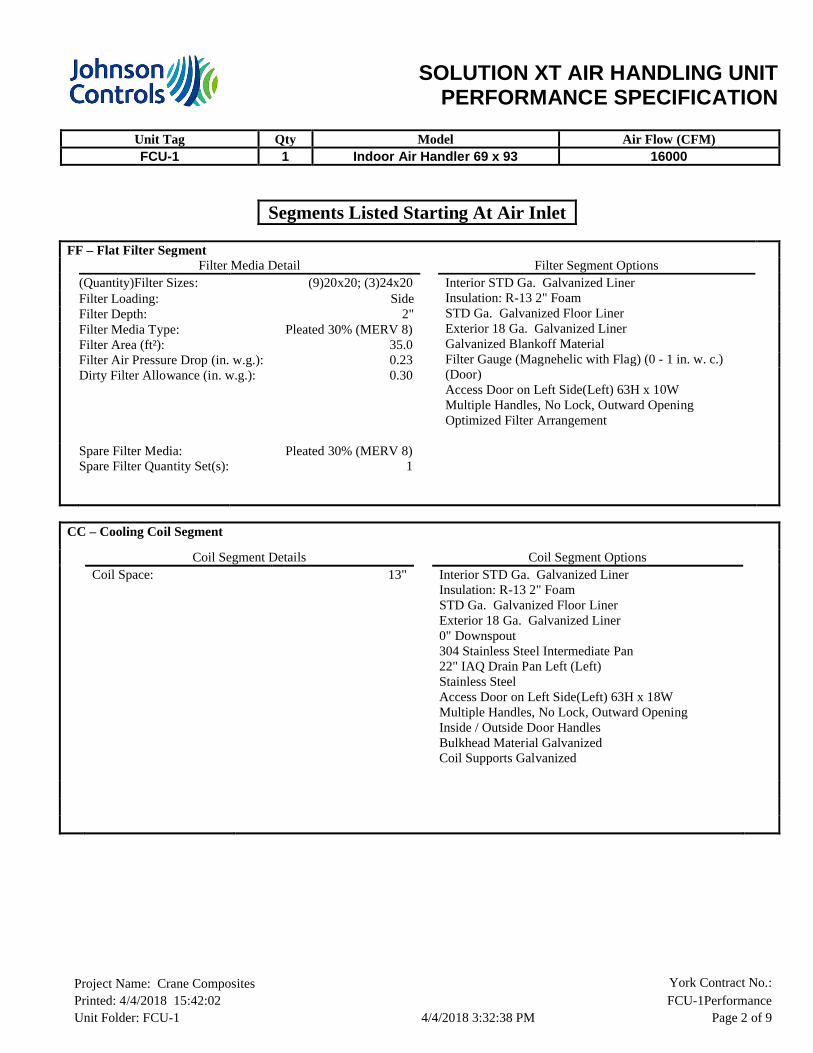
Unit Tag Qty Model Air Flow (CFM)FCU-1 1 Indoor Air Handler 69 x 93 16000
Project Name: Crane Composites York Contract No.: Printed: 4/4/2018 15:42:02 FCU-1PerformanceUnit Folder: FCU-1 4/4/2018 3:32:38 PM Page 1 of 9
Unit Sequence
Tier 1 FPS <<< CC <<< FF
Basic Unit Options
Insulation Type: (Refer to Each Segment)Base Rail Height: 6" Formed Steel NON Welded
BasePerformance: High Performance
Statement of compliance of standard units.
Solution XT AHU's meet IBC seismic requirements for non-critical equipment (Ip = 1.0) for locations with design spectral response Sds <= 0.43. Units must be rigid mounted.
The anchorage of the unit to the ground or building structure needs to be evaluated by and is the responsibility of the engineer of record.
Specification of seismic requirements is the responsibility of the project design engineer. If formal certification is required, please contact your sales representative and/or application engineer for review. Certain application and site requirements may require additional cost and/or lead time.
*Note:Component locations are listed as Segment Hand (Unit Hand) : ex. Left (Right) See Submittal Drawing for additional details
SOLUTION XT AIR HANDLING UNITPERFORMANCE SPECIFICATION
Unit Tag Qty Model Air Flow (CFM)FCU-1 1 Indoor Air Handler 69 x 93 16000
Project Name: Crane Composites York Contract No.: Printed: 4/4/2018 15:42:02 FCU-1PerformanceUnit Folder: FCU-1 4/4/2018 3:32:38 PM Page 2 of 9
Segments Listed Starting At Air Inlet
FF – Flat Filter SegmentFilter Media Detail Filter Segment Options
(Quantity)Filter Sizes: (9)20x20; (3)24x20 Interior STD Ga. Galvanized Liner Insulation: R-13 2" FoamSTD Ga. Galvanized Floor LinerExterior 18 Ga. Galvanized Liner Galvanized Blankoff MaterialFilter Gauge (Magnehelic with Flag) (0 - 1 in. w. c.) (Door)Access Door on Left Side(Left) 63H x 10WMultiple Handles, No Lock, Outward OpeningOptimized Filter Arrangement
Filter Loading: SideFilter Depth: 2"Filter Media Type: Pleated 30% (MERV 8)Filter Area (ft²): 35.0Filter Air Pressure Drop (in. w.g.): 0.23Dirty Filter Allowance (in. w.g.): 0.30
Spare Filter Media:Spare Filter Quantity Set(s):
Pleated 30% (MERV 8)1
CC – Cooling Coil Segment
Coil Segment Details Coil Segment OptionsCoil Space: 13" Interior STD Ga. Galvanized Liner
Insulation: R-13 2" FoamSTD Ga. Galvanized Floor LinerExterior 18 Ga. Galvanized Liner 0" Downspout304 Stainless Steel Intermediate Pan22" IAQ Drain Pan Left (Left)Stainless SteelAccess Door on Left Side(Left) 63H x 18WMultiple Handles, No Lock, Outward OpeningInside / Outside Door HandlesBulkhead Material GalvanizedCoil Supports Galvanized

SOLUTION XT AIR HANDLING UNITPERFORMANCE SPECIFICATION
Unit Tag Qty Model Air Flow (CFM)FCU-1 1 Indoor Air Handler 69 x 93 16000
Project Name: Crane Composites York Contract No.: Printed: 4/4/2018 15:42:02 FCU-1PerformanceUnit Folder: FCU-1 4/4/2018 3:32:38 PM Page 3 of 9
FS - Supply Plenum Fan SegmentSegment Details Fan Segment Options
Segment Air Pressure Drop (in. w.g.): 0.43 1" Spring IsolatorInterior STD Ga. Galvanized Liner Insulation: R-13 2" FoamSTD Ga. Galvanized Floor LinerExterior 18 Ga. Galvanized Liner Convenience Outlet 20AFan AFMS Airflow Constant (K Factor): 4156.00Transducer Range: 0-25"Access Door on Left Side(Left) 63H x 18WMultiple Handles, No Lock, Outward OpeningInside / Outside Door Handles
Air Flow per Fan (CFM): 16000Air Flow Total (CFM): 16000Altitude (ft.): 630TSP/ESP (in. w.g.): 2.84/ 1.25Air Inlet: Front(Front)Fan Discharge: Rear-1(Rear)
Fan DetailType: PL-DDPG2Size: 270-9Construction: IIBearing Options: NoneFan RPM: 1796BHP/(Pe/kW)*: 13.67Total Fan BHP/(Pe/kW)*: 13.67Outlet Velocity (ft/min): N/A% Wheel Width: 100.00% Wheel Diameter: 100.00
Motor Detail (per motor)Motor Type: WEG TEFC Premium EfficiencyHP/kW* 15.0Voltage/Phase/Frequency: 460/3/60 HzInsulation Class: FMotor RPM: 1800Frame Size: 254Shaft Grounding RingLocation N/ADrive Type: Direct DriveBelt Drive Type: N/A
Full Load Amps (FLA): 18.20Efficiency: 92.4%

SOLUTION XT AIR HANDLING UNITPERFORMANCE SPECIFICATION
Unit Tag Qty Model Air Flow (CFM)FCU-1 1 Indoor Air Handler 69 x 93 16000
Project Name: Crane Composites York Contract No.: Printed: 4/4/2018 15:42:02 FCU-1PerformanceUnit Folder: FCU-1 4/4/2018 3:32:38 PM Page 4 of 9
Motor Control – Supply Fan
Motor Control DetailsMotor Control Type: Variable Frequency Drive
Motor Control Options EnvironmentalNon Fused DisconnectRFI/EMI EMC FilterSwinging DC Line Choke (equivalent to 5% Input Line Reactor)Modbus RTU, Johnson N2, BACnet
Ambient Temperature (°F): 5 to 104Storage Temperature (°F): -40 to 158Humidity: MAX 95% RH non-condensingAltitude: 3,280 ft. without derate (1% derate
for each additional 328 ft.)Enclosure: NEMA 1
InputRated Input Voltage: 380/400/415/440/460/480 +10% -15% VAC 3 phaseRated Input Current Amps: 23.00Heat Loss in Watts 100% Load: 337.00Efficiency (%): 98.00
OutputOutput Current Amps: 23.0Overload Current Rating: 110% for 1 minute every 10 minutes
Drives are rated for use below 3,280 ft and 104°F.Use Airmod AYK Derating Charts for use above these limits.
Copper Conductors Only
SOLUTION XT AIR HANDLING UNITPERFORMANCE SPECIFICATION
Unit Tag Qty Model Air Flow (CFM)FCU-1 1 Indoor Air Handler 69 x 93 16000
Project Name: Crane Composites York Contract No.: Printed: 4/4/2018 15:42:02 FCU-1PerformanceUnit Folder: FCU-1 4/4/2018 3:32:38 PM Page 5 of 9
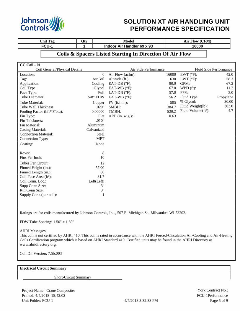
Coils & Spacers Listed Starting In Direction Of Air Flow
CC Coil - 01 Coil General/Physical Details Air Side Performance Fluid Side PerformanceLocation: 0 Air Flow (acfm): 16000 EWT (°F):
LWT (°F):GPM:WPD (ft):FPS:Fluid Type:% Glycol:Fluid Weight(lb):Fluid Volume(ft³):
42.058.367.211.2
3.0Propylene
30.00303.0
4.7
Tag: AirCoil Altitude (ft.): 630Application: Cooling EAT-DB (°F): 80.0Coil Type: Glycol EAT-WB (°F): 67.0Face Type: Full LAT-DB (°F): 57.0Tube Diameter: 5/8" FDW LAT-WB (°F): 56.2
Tube Material: Copper FV (ft/min): 505Tube Wall Thickness: .020" SMBH: 384.7Fouling Factor (hft²°F/btu): 0.00000 TMBH: 520.2Fin Type: Flat APD (in. w.g.): 0.63Fin Thickness: .010" Fin Material: AluminumCasing Material: GalvanizedConnection Material: SteelConnection Type: MPTCoating: None
Rows: 8Fins Per Inch: 10
Tubes Per Circuit: 12Finned Height (in.): 57.00Finned Length (in.): 80Coil Face Area (ft²): 31.7Coil Conn. Loc.: Left(Left)Supp Conn Size:Rtn Conn Size:Supply Conn.(per coil):
3"3"1
Ratings are for coils manufactured by Johnson Controls, Inc., 507 E. Michigan St., Milwaukee WI 53202.
FDW Tube Spacing: 1.50" x 1.30"
AHRI Messages:This coil is not certified by AHRI 410. This coil is rated in accordance with the AHRI Forced-Circulation Air-Cooling and Air-Heating Coils Certification program which is based on AHRI Standard 410. Certified units may be found in the AHRI Directory at www.ahridirectory.org.
Coil Dll Version: 7.5b.003
Electrical Circuit Summary
Short-Circuit Summary

SOLUTION XT AIR HANDLING UNITPERFORMANCE SPECIFICATION
Unit Tag Qty Model Air Flow (CFM)FCU-1 1 Indoor Air Handler 69 x 93 16000
Project Name: Crane Composites York Contract No.: Printed: 4/4/2018 15:42:02 FCU-1PerformanceUnit Folder: FCU-1 4/4/2018 3:32:38 PM Page 6 of 9
5 kA rms Symmetrical 480 V Maximum
Circuit 1 Circuit 1 Electrical DetailsSupply Fan Motor Control Full Load Amps (FLA): 18.2
Minimum Circuit Ampacity (MCA): 22.8Maximum Overcurrent Protection: 40.00
Circuit 2 Circuit 2 Electrical DetailsLights and Outlets
Maximum Overcurrent Protection: 20.00
Static Pressure Summary
Segment Component Supply (in.
w.g.)
Return Fan
(in. w.g.)
FF Flat Filter
CC Variable Length Cooling CoilFS-SWSI Supply Fan
2" Pleated 30% (MERV 8)Dirty Filter AllowanceCooling 8 rows 10 finsOpening Pressure DropExternal Static Pressure - User Entered Pressure Drop
0.230.300.630.431.25
Total 2.84 0.00
Air handling unit parameters vary depending on conditions. Parameters such as airflows, air pressure drops, and coil capacities are shown for design conditions.
SOLUTION XT AIR HANDLING UNITPERFORMANCE SPECIFICATION
Unit Tag Qty Model Air Flow (CFM)FCU-1 1 Indoor Air Handler 69 x 93 16000
Project Name: Crane Composites York Contract No.: Printed: 4/4/2018 15:42:02 FCU-1PerformanceUnit Folder: FCU-1 4/4/2018 3:32:38 PM Page 7 of 9
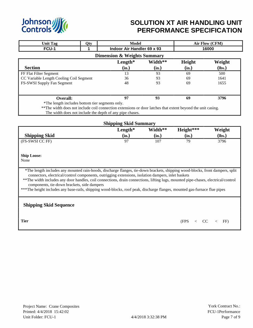
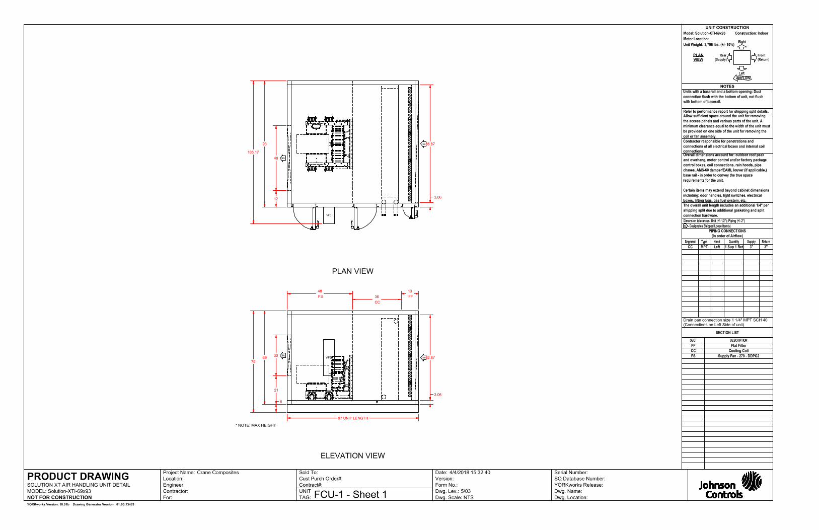
Dimension & Weights Summary
SectionLength*
(in.)Width**
(in.)Height
(in.)Weight
(lbs.)FF Flat Filter SegmentCC Variable Length Cooling Coil SegmentFS-SWSI Supply Fan Segment
133648
939393
696969
50016411655
Overall: 97 93 69 3796 *The length includes bottom tier segments only.
**The width does not include coil connection extensions or door latches that extent beyond the unit casing. The width does not include the depth of any pipe chases.
Shipping Skid Summary
Shipping SkidLength*
(in.)Width**
(in.)Height***
(in.)Weight
(lbs.)(FS-SWSI CC FF)
Ship Loose:None
97 107 79 3796
*The length includes any mounted rain-hoods, discharge flanges, tie-down brackets, shipping wood-blocks, front dampers, split connectors, electrical/control components, outrigging extensions, isolation dampers, inlet baskets
**The width includes any door handles, coil connections, drain connections, lifting lugs, mounted pipe-chases, electrical/control components, tie-down brackets, side dampers
***The height includes any base-rails, shipping wood-blocks, roof peak, discharge flanges, mounted gas-furnace flue pipes
Shipping Skid Sequence
Tier 1
(FPS < CC < FF)

SOLUTION XT AIR HANDLING UNITPERFORMANCE SPECIFICATION
Unit Tag Qty Model Air Flow (CFM)FCU-1 1 Indoor Air Handler 69 x 93 16000
Project Name: Crane Composites York Contract No.: Printed: 4/4/2018 15:42:02 FCU-1PerformanceUnit Folder: FCU-1 4/4/2018 3:32:38 PM Page 8 of 9
Sound Summary
Octave Band Sound Power Levels (dB Re. 1 picowatt)
63 125 250 500 1000 2000 4000 8000 dBADucted Discharge Rear-1, FS 89 86 92 90 87 83 81 79Return Air INLET, FF 78 82 93 79 75 71 67 63
Sound data tested in accordance with AHRI-260 (2001), Standard for Sound Rating of Ducted Air Moving and Conditioning Equipment.
Notes:1. The overall A-weighted sound power level is only applicable to sound radiation outdoors and casing radiated
sound. This metric does not apply to ducted components2. Return air sound powers are estimated using 100% of unit flow.

SOLUTION XT AIR HANDLING UNITPERFORMANCE SPECIFICATION
Unit Tag Qty Model Air Flow (CFM)FCU-1 1 Indoor Air Handler 69 x 93 16000
Project Name: Crane Composites York Contract No.: Printed: 4/4/2018 15:42:02 FCU-1PerformanceUnit Folder: FCU-1 4/4/2018 3:32:38 PM Page 9 of 9
Recommended Trap Height Summary
Applicable Fan TSP Positive or Calculated Dimensions Recommended Base Rail
Segment Fan [in H2O] Negative H X H + X H H + X Height
CC Supply Fan 2.84" Negative 3.84" 1.92" 5.76" 4.00" 6.00" 6"
Notes:Formulas and calculations are recommendations only. Contractor shall determine actual dimensions required for each trap based on jobsite conditions, and application requirements.Refer to section 2 (Installation) of the IOM for more information.
SOLUTION XT AIR HANDLING UNITPERFORMANCE SPECIFICATION
Unit Tag Qty Model Air Flow (CFM)FCU-2 1 Indoor Air Handler 69 x 93 16000
Project Name: Crane Composites York Contract No.: Printed: 4/4/2018 15:42:04 FCU-2PerformanceUnit Folder: FCU-2 4/4/2018 3:31:37 PM Page 1 of 9
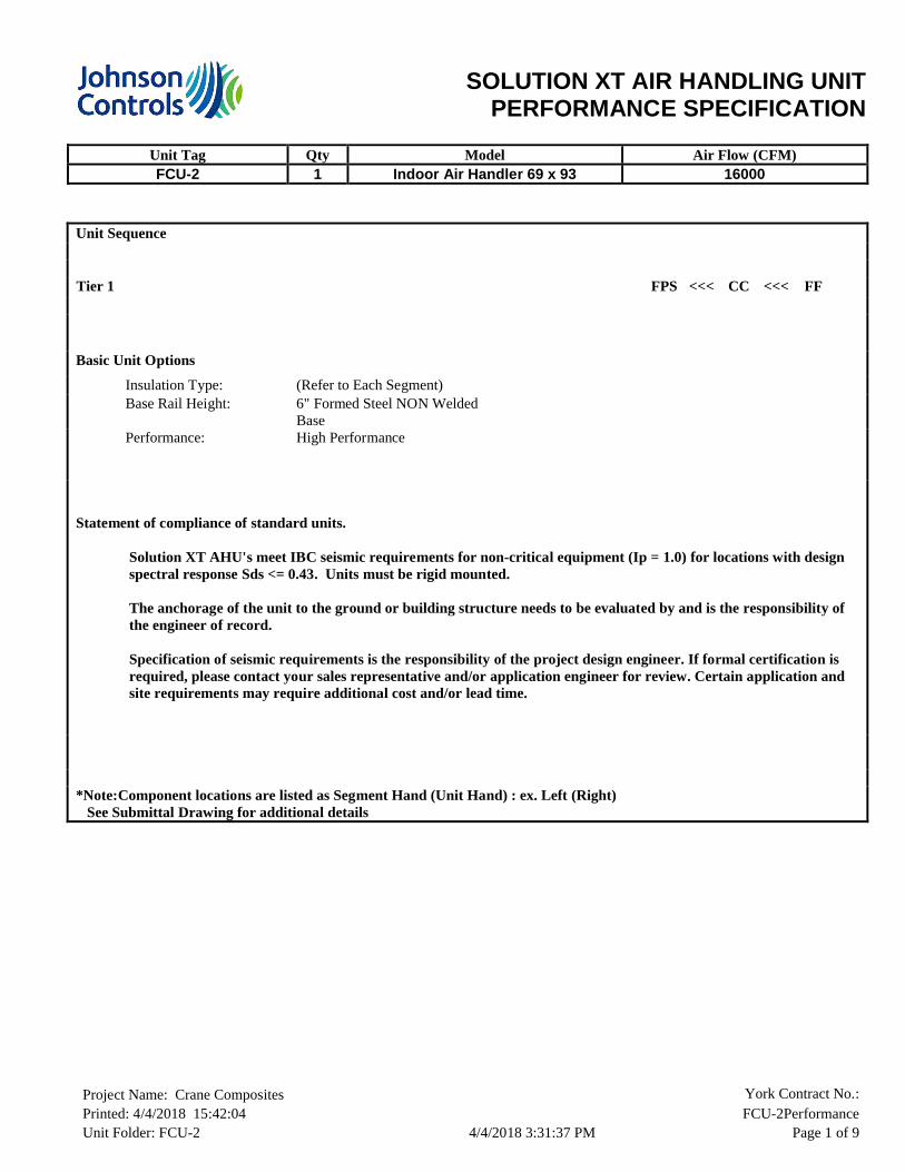
Unit Sequence
Tier 1 FPS <<< CC <<< FF
Basic Unit Options
Insulation Type: (Refer to Each Segment)Base Rail Height: 6" Formed Steel NON Welded
BasePerformance: High Performance
Statement of compliance of standard units.
Solution XT AHU's meet IBC seismic requirements for non-critical equipment (Ip = 1.0) for locations with design spectral response Sds <= 0.43. Units must be rigid mounted.
The anchorage of the unit to the ground or building structure needs to be evaluated by and is the responsibility of the engineer of record.
Specification of seismic requirements is the responsibility of the project design engineer. If formal certification is required, please contact your sales representative and/or application engineer for review. Certain application and site requirements may require additional cost and/or lead time.
*Note:Component locations are listed as Segment Hand (Unit Hand) : ex. Left (Right) See Submittal Drawing for additional details

SOLUTION XT AIR HANDLING UNITPERFORMANCE SPECIFICATION
Unit Tag Qty Model Air Flow (CFM)FCU-2 1 Indoor Air Handler 69 x 93 16000
Project Name: Crane Composites York Contract No.: Printed: 4/4/2018 15:42:04 FCU-2PerformanceUnit Folder: FCU-2 4/4/2018 3:31:37 PM Page 2 of 9
Segments Listed Starting At Air Inlet
FF – Flat Filter SegmentFilter Media Detail Filter Segment Options
(Quantity)Filter Sizes: (9)20x20; (3)24x20 Interior STD Ga. Galvanized Liner Insulation: R-13 2" FoamSTD Ga. Galvanized Floor LinerExterior 18 Ga. Galvanized Liner Galvanized Blankoff MaterialFilter Gauge (Magnehelic with Flag) (0 - 1 in. w. c.) (Door)Access Door on Left Side(Left) 63H x 10WMultiple Handles, No Lock, Outward OpeningOptimized Filter Arrangement
Filter Loading: SideFilter Depth: 2"Filter Media Type: Pleated 30% (MERV 8)Filter Area (ft²): 35.0Filter Air Pressure Drop (in. w.g.): 0.23Dirty Filter Allowance (in. w.g.): 0.30
Spare Filter Media:Spare Filter Quantity Set(s):
Pleated 30% (MERV 8)1
CC – Cooling Coil Segment
Coil Segment Details Coil Segment OptionsCoil Space: 13" Interior STD Ga. Galvanized Liner
Insulation: R-13 2" FoamSTD Ga. Galvanized Floor LinerExterior 18 Ga. Galvanized Liner 0" Downspout304 Stainless Steel Intermediate Pan22" IAQ Drain Pan Left (Left)Stainless SteelAccess Door on Left Side(Left) 63H x 18WMultiple Handles, No Lock, Outward OpeningInside / Outside Door HandlesBulkhead Material GalvanizedCoil Supports Galvanized

SOLUTION XT AIR HANDLING UNITPERFORMANCE SPECIFICATION
Unit Tag Qty Model Air Flow (CFM)FCU-2 1 Indoor Air Handler 69 x 93 16000
Project Name: Crane Composites York Contract No.: Printed: 4/4/2018 15:42:04 FCU-2PerformanceUnit Folder: FCU-2 4/4/2018 3:31:37 PM Page 3 of 9
FS - Supply Plenum Fan SegmentSegment Details Fan Segment Options
Segment Air Pressure Drop (in. w.g.): 0.43 1" Spring IsolatorInterior STD Ga. Galvanized Liner Insulation: R-13 2" FoamSTD Ga. Galvanized Floor LinerExterior 18 Ga. Galvanized Liner Convenience Outlet 20AFan AFMS Airflow Constant (K Factor): 4156.00Transducer Range: 0-25"Access Door on Left Side(Left) 63H x 18WMultiple Handles, No Lock, Outward OpeningInside / Outside Door Handles
Air Flow per Fan (CFM): 16000Air Flow Total (CFM): 16000Altitude (ft.): 630TSP/ESP (in. w.g.): 2.84/ 1.25Air Inlet: Front(Front)Fan Discharge: Rear-1(Rear)
Fan DetailType: PL-DDPG2Size: 270-9Construction: IIBearing Options: NoneFan RPM: 1796BHP/(Pe/kW)*: 13.67Total Fan BHP/(Pe/kW)*: 13.67Outlet Velocity (ft/min): N/A% Wheel Width: 100.00% Wheel Diameter: 100.00
Motor Detail (per motor)Motor Type: WEG TEFC Premium EfficiencyHP/kW* 15.0Voltage/Phase/Frequency: 460/3/60 HzInsulation Class: FMotor RPM: 1800Frame Size: 254Shaft Grounding RingLocation N/ADrive Type: Direct DriveBelt Drive Type: N/A
Full Load Amps (FLA): 18.20Efficiency: 92.4%

SOLUTION XT AIR HANDLING UNITPERFORMANCE SPECIFICATION
Unit Tag Qty Model Air Flow (CFM)FCU-2 1 Indoor Air Handler 69 x 93 16000
Project Name: Crane Composites York Contract No.: Printed: 4/4/2018 15:42:04 FCU-2PerformanceUnit Folder: FCU-2 4/4/2018 3:31:37 PM Page 4 of 9
Motor Control – Supply Fan
Motor Control DetailsMotor Control Type: Variable Frequency Drive
Motor Control Options EnvironmentalNon Fused DisconnectRFI/EMI EMC FilterSwinging DC Line Choke (equivalent to 5% Input Line Reactor)Modbus RTU, Johnson N2, BACnet
Ambient Temperature (°F): 5 to 104Storage Temperature (°F): -40 to 158Humidity: MAX 95% RH non-condensingAltitude: 3,280 ft. without derate (1% derate
for each additional 328 ft.)Enclosure: NEMA 1
InputRated Input Voltage: 380/400/415/440/460/480 +10% -15% VAC 3 phaseRated Input Current Amps: 23.00Heat Loss in Watts 100% Load: 337.00Efficiency (%): 98.00
OutputOutput Current Amps: 23.0Overload Current Rating: 110% for 1 minute every 10 minutes
Drives are rated for use below 3,280 ft and 104°F.Use Airmod AYK Derating Charts for use above these limits.
Copper Conductors Only

SOLUTION XT AIR HANDLING UNITPERFORMANCE SPECIFICATION
Unit Tag Qty Model Air Flow (CFM)FCU-2 1 Indoor Air Handler 69 x 93 16000
Project Name: Crane Composites York Contract No.: Printed: 4/4/2018 15:42:04 FCU-2PerformanceUnit Folder: FCU-2 4/4/2018 3:31:37 PM Page 5 of 9
Coils & Spacers Listed Starting In Direction Of Air Flow
CC Coil - 01 Coil General/Physical Details Air Side Performance Fluid Side PerformanceLocation: 0 Air Flow (acfm): 16000 EWT (°F):
LWT (°F):GPM:WPD (ft):FPS:Fluid Type:% Glycol:Fluid Weight(lb):Fluid Volume(ft³):
42.058.367.211.2
3.0Propylene
30.00303.0
4.7
Tag: AirCoil Altitude (ft.): 630Application: Cooling EAT-DB (°F): 80.0Coil Type: Glycol EAT-WB (°F): 67.0Face Type: Full LAT-DB (°F): 57.0Tube Diameter: 5/8" FDW LAT-WB (°F): 56.2
Tube Material: Copper FV (ft/min): 505Tube Wall Thickness: .020" SMBH: 384.7Fouling Factor (hft²°F/btu): 0.00000 TMBH: 520.2Fin Type: Flat APD (in. w.g.): 0.63Fin Thickness: .010" Fin Material: AluminumCasing Material: GalvanizedConnection Material: SteelConnection Type: MPTCoating: None
Rows: 8Fins Per Inch: 10
Tubes Per Circuit: 12Finned Height (in.): 57.00Finned Length (in.): 80Coil Face Area (ft²): 31.7Coil Conn. Loc.: Left(Left)Supp Conn Size:Rtn Conn Size:Supply Conn.(per coil):
3"3"1
Ratings are for coils manufactured by Johnson Controls, Inc., 507 E. Michigan St., Milwaukee WI 53202.
FDW Tube Spacing: 1.50" x 1.30"
AHRI Messages:This coil is not certified by AHRI 410. This coil is rated in accordance with the AHRI Forced-Circulation Air-Cooling and Air-Heating Coils Certification program which is based on AHRI Standard 410. Certified units may be found in the AHRI Directory at www.ahridirectory.org.
Coil Dll Version: 7.5b.003
Electrical Circuit Summary
Short-Circuit Summary
SOLUTION XT AIR HANDLING UNITPERFORMANCE SPECIFICATION
Unit Tag Qty Model Air Flow (CFM)FCU-2 1 Indoor Air Handler 69 x 93 16000
Project Name: Crane Composites York Contract No.: Printed: 4/4/2018 15:42:04 FCU-2PerformanceUnit Folder: FCU-2 4/4/2018 3:31:37 PM Page 6 of 9
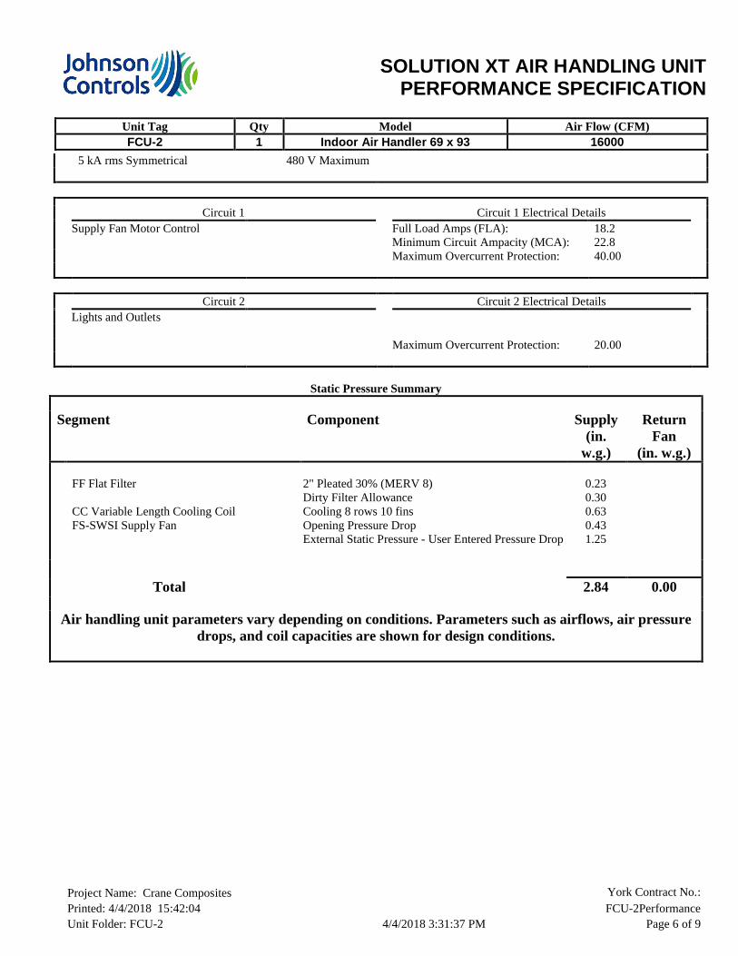
5 kA rms Symmetrical 480 V Maximum
Circuit 1 Circuit 1 Electrical DetailsSupply Fan Motor Control Full Load Amps (FLA): 18.2
Minimum Circuit Ampacity (MCA): 22.8Maximum Overcurrent Protection: 40.00
Circuit 2 Circuit 2 Electrical DetailsLights and Outlets
Maximum Overcurrent Protection: 20.00
Static Pressure Summary
Segment Component Supply (in.
w.g.)
Return Fan
(in. w.g.)
FF Flat Filter
CC Variable Length Cooling CoilFS-SWSI Supply Fan
2" Pleated 30% (MERV 8)Dirty Filter AllowanceCooling 8 rows 10 finsOpening Pressure DropExternal Static Pressure - User Entered Pressure Drop
0.230.300.630.431.25
Total 2.84 0.00
Air handling unit parameters vary depending on conditions. Parameters such as airflows, air pressure drops, and coil capacities are shown for design conditions.

SOLUTION XT AIR HANDLING UNITPERFORMANCE SPECIFICATION
Unit Tag Qty Model Air Flow (CFM)FCU-2 1 Indoor Air Handler 69 x 93 16000
Project Name: Crane Composites York Contract No.: Printed: 4/4/2018 15:42:04 FCU-2PerformanceUnit Folder: FCU-2 4/4/2018 3:31:37 PM Page 7 of 9
Dimension & Weights Summary
SectionLength*
(in.)Width**
(in.)Height
(in.)Weight
(lbs.)FF Flat Filter SegmentCC Variable Length Cooling Coil SegmentFS-SWSI Supply Fan Segment
133648
939393
696969
50016411655
Overall: 97 93 69 3796 *The length includes bottom tier segments only.
**The width does not include coil connection extensions or door latches that extent beyond the unit casing. The width does not include the depth of any pipe chases.
Shipping Skid Summary
Shipping SkidLength*
(in.)Width**
(in.)Height***
(in.)Weight
(lbs.)(FS-SWSI CC FF)
Ship Loose:None
97 107 79 3796
*The length includes any mounted rain-hoods, discharge flanges, tie-down brackets, shipping wood-blocks, front dampers, split connectors, electrical/control components, outrigging extensions, isolation dampers, inlet baskets
**The width includes any door handles, coil connections, drain connections, lifting lugs, mounted pipe-chases, electrical/control components, tie-down brackets, side dampers
***The height includes any base-rails, shipping wood-blocks, roof peak, discharge flanges, mounted gas-furnace flue pipes
Shipping Skid Sequence
Tier 1
(FPS < CC < FF)

SOLUTION XT AIR HANDLING UNITPERFORMANCE SPECIFICATION
Unit Tag Qty Model Air Flow (CFM)FCU-2 1 Indoor Air Handler 69 x 93 16000
Project Name: Crane Composites York Contract No.: Printed: 4/4/2018 15:42:04 FCU-2PerformanceUnit Folder: FCU-2 4/4/2018 3:31:37 PM Page 8 of 9
Sound Summary
Octave Band Sound Power Levels (dB Re. 1 picowatt)
63 125 250 500 1000 2000 4000 8000 dBADucted Discharge Rear-1, FS 89 86 92 90 87 83 81 79Return Air INLET, FF 78 82 93 79 75 71 67 63
Sound data tested in accordance with AHRI-260 (2001), Standard for Sound Rating of Ducted Air Moving and Conditioning Equipment.
Notes:1. The overall A-weighted sound power level is only applicable to sound radiation outdoors and casing radiated
sound. This metric does not apply to ducted components2. Return air sound powers are estimated using 100% of unit flow.

SOLUTION XT AIR HANDLING UNITPERFORMANCE SPECIFICATION
Unit Tag Qty Model Air Flow (CFM)FCU-2 1 Indoor Air Handler 69 x 93 16000
Project Name: Crane Composites York Contract No.: Printed: 4/4/2018 15:42:04 FCU-2PerformanceUnit Folder: FCU-2 4/4/2018 3:31:37 PM Page 9 of 9
Recommended Trap Height Summary
Applicable Fan TSP Positive or Calculated Dimensions Recommended Base Rail
Segment Fan [in H2O] Negative H X H + X H H + X Height
CC Supply Fan 2.84" Negative 3.84" 1.92" 5.76" 4.00" 6.00" 6"
Notes:Formulas and calculations are recommendations only. Contractor shall determine actual dimensions required for each trap based on jobsite conditions, and application requirements.Refer to section 2 (Installation) of the IOM for more information.

SOLUTION XT AIR HANDLING UNITPERFORMANCE SPECIFICATION
Unit Tag Qty Model Air Flow (CFM)FCU-3 1 Indoor Air Handler 69 x 93 16000
Project Name: Crane Composites York Contract No.: Printed: 4/4/2018 15:42:05 FCU-3PerformanceUnit Folder: FCU-3 4/4/2018 3:34:30 PM Page 1 of 9
Unit Sequence
Tier 1 FPS <<< CC <<< FF
Basic Unit Options
Insulation Type: (Refer to Each Segment)Base Rail Height: 6" Formed Steel NON Welded
BasePerformance: High Performance
Statement of compliance of standard units.
Solution XT AHU's meet IBC seismic requirements for non-critical equipment (Ip = 1.0) for locations with design spectral response Sds <= 0.43. Units must be rigid mounted.
The anchorage of the unit to the ground or building structure needs to be evaluated by and is the responsibility of the engineer of record.
Specification of seismic requirements is the responsibility of the project design engineer. If formal certification is required, please contact your sales representative and/or application engineer for review. Certain application and site requirements may require additional cost and/or lead time.
*Note:Component locations are listed as Segment Hand (Unit Hand) : ex. Left (Right) See Submittal Drawing for additional details

SOLUTION XT AIR HANDLING UNITPERFORMANCE SPECIFICATION
Unit Tag Qty Model Air Flow (CFM)FCU-3 1 Indoor Air Handler 69 x 93 16000
Project Name: Crane Composites York Contract No.: Printed: 4/4/2018 15:42:05 FCU-3PerformanceUnit Folder: FCU-3 4/4/2018 3:34:30 PM Page 2 of 9
Segments Listed Starting At Air Inlet
FF – Flat Filter SegmentFilter Media Detail Filter Segment Options
(Quantity)Filter Sizes: (9)20x20; (3)24x20 Interior STD Ga. Galvanized Liner Insulation: R-13 2" FoamSTD Ga. Galvanized Floor LinerExterior 18 Ga. Galvanized Liner Galvanized Blankoff MaterialFilter Gauge (Magnehelic with Flag) (0 - 1 in. w. c.) (Door)Access Door on Left Side(Left) 63H x 10WMultiple Handles, No Lock, Outward OpeningOptimized Filter Arrangement
Filter Loading: SideFilter Depth: 2"Filter Media Type: Pleated 30% (MERV 8)Filter Area (ft²): 35.0Filter Air Pressure Drop (in. w.g.): 0.23Dirty Filter Allowance (in. w.g.): 0.30
Spare Filter Media:Spare Filter Quantity Set(s):
Pleated 30% (MERV 8)1
CC – Cooling Coil Segment
Coil Segment Details Coil Segment OptionsCoil Space: 13" Interior STD Ga. Galvanized Liner
Insulation: R-13 2" FoamSTD Ga. Galvanized Floor LinerExterior 18 Ga. Galvanized Liner 0" Downspout304 Stainless Steel Intermediate Pan22" IAQ Drain Pan Left (Left)Stainless SteelAccess Door on Left Side(Left) 63H x 18WMultiple Handles, No Lock, Outward OpeningInside / Outside Door HandlesBulkhead Material GalvanizedCoil Supports Galvanized

SOLUTION XT AIR HANDLING UNITPERFORMANCE SPECIFICATION
Unit Tag Qty Model Air Flow (CFM)FCU-3 1 Indoor Air Handler 69 x 93 16000
Project Name: Crane Composites York Contract No.: Printed: 4/4/2018 15:42:05 FCU-3PerformanceUnit Folder: FCU-3 4/4/2018 3:34:30 PM Page 3 of 9
FS - Supply Plenum Fan SegmentSegment Details Fan Segment Options
Segment Air Pressure Drop (in. w.g.): 0.43 1" Spring IsolatorInterior STD Ga. Galvanized Liner Insulation: R-13 2" FoamSTD Ga. Galvanized Floor LinerExterior 18 Ga. Galvanized Liner Convenience Outlet 20AFan AFMS Airflow Constant (K Factor): 4156.00Transducer Range: 0-25"Access Door on Left Side(Left) 63H x 18WMultiple Handles, No Lock, Outward OpeningInside / Outside Door Handles
Air Flow per Fan (CFM): 16000Air Flow Total (CFM): 16000Altitude (ft.): 630TSP/ESP (in. w.g.): 2.34/ 0.75Air Inlet: Front(Front)Fan Discharge: Rear-1(Rear)
Fan DetailType: PL-DDPG2Size: 270-12Construction: IIBearing Options: NoneFan RPM: 1537BHP/(Pe/kW)*: 11.13Total Fan BHP/(Pe/kW)*: 11.13Outlet Velocity (ft/min): N/A% Wheel Width: 120.00% Wheel Diameter: 100.00
Motor Detail (per motor)Motor Type: WEG TEFC Premium EfficiencyHP/kW* 15.0Voltage/Phase/Frequency: 460/3/60 HzInsulation Class: FMotor RPM: 1200Frame Size: 284Shaft Grounding RingLocation N/ADrive Type: Direct DriveBelt Drive Type: N/A
Full Load Amps (FLA): 17.90Efficiency: 91.7%

SOLUTION XT AIR HANDLING UNITPERFORMANCE SPECIFICATION
Unit Tag Qty Model Air Flow (CFM)FCU-3 1 Indoor Air Handler 69 x 93 16000
Project Name: Crane Composites York Contract No.: Printed: 4/4/2018 15:42:05 FCU-3PerformanceUnit Folder: FCU-3 4/4/2018 3:34:30 PM Page 4 of 9
Motor Control – Supply Fan
Motor Control DetailsMotor Control Type: Variable Frequency Drive
Motor Control Options EnvironmentalNon Fused DisconnectRFI/EMI EMC FilterSwinging DC Line Choke (equivalent to 5% Input Line Reactor)Modbus RTU, Johnson N2, BACnet
Ambient Temperature (°F): 5 to 104Storage Temperature (°F): -40 to 158Humidity: MAX 95% RH non-condensingAltitude: 3,280 ft. without derate (1% derate
for each additional 328 ft.)Enclosure: NEMA 1
InputRated Input Voltage: 380/400/415/440/460/480 +10% -15% VAC 3 phaseRated Input Current Amps: 23.00Heat Loss in Watts 100% Load: 337.00Efficiency (%): 98.00
OutputOutput Current Amps: 23.0Overload Current Rating: 110% for 1 minute every 10 minutes
Drives are rated for use below 3,280 ft and 104°F.Use Airmod AYK Derating Charts for use above these limits.
Copper Conductors Only

SOLUTION XT AIR HANDLING UNITPERFORMANCE SPECIFICATION
Unit Tag Qty Model Air Flow (CFM)FCU-3 1 Indoor Air Handler 69 x 93 16000
Project Name: Crane Composites York Contract No.: Printed: 4/4/2018 15:42:05 FCU-3PerformanceUnit Folder: FCU-3 4/4/2018 3:34:30 PM Page 5 of 9
Coils & Spacers Listed Starting In Direction Of Air Flow
CC Coil - 01 Coil General/Physical Details Air Side Performance Fluid Side PerformanceLocation: 0 Air Flow (acfm): 16000 EWT (°F):
LWT (°F):GPM:WPD (ft):FPS:Fluid Type:% Glycol:Fluid Weight(lb):Fluid Volume(ft³):
42.058.367.211.2
3.0Propylene
30.00303.0
4.7
Tag: AirCoil Altitude (ft.): 630Application: Cooling EAT-DB (°F): 80.0Coil Type: Glycol EAT-WB (°F): 67.0Face Type: Full LAT-DB (°F): 57.0Tube Diameter: 5/8" FDW LAT-WB (°F): 56.2
Tube Material: Copper FV (ft/min): 505Tube Wall Thickness: .020" SMBH: 384.7Fouling Factor (hft²°F/btu): 0.00000 TMBH: 520.2Fin Type: Flat APD (in. w.g.): 0.63Fin Thickness: .010" Fin Material: AluminumCasing Material: GalvanizedConnection Material: SteelConnection Type: MPTCoating: None
Rows: 8Fins Per Inch: 10
Tubes Per Circuit: 12Finned Height (in.): 57.00Finned Length (in.): 80Coil Face Area (ft²): 31.7Coil Conn. Loc.: Left(Left)Supp Conn Size:Rtn Conn Size:Supply Conn.(per coil):
3"3"1
Ratings are for coils manufactured by Johnson Controls, Inc., 507 E. Michigan St., Milwaukee WI 53202.
FDW Tube Spacing: 1.50" x 1.30"
AHRI Messages:This coil is not certified by AHRI 410. This coil is rated in accordance with the AHRI Forced-Circulation Air-Cooling and Air-Heating Coils Certification program which is based on AHRI Standard 410. Certified units may be found in the AHRI Directory at www.ahridirectory.org.
Coil Dll Version: 7.5b.003
Electrical Circuit Summary
Short-Circuit Summary

SOLUTION XT AIR HANDLING UNITPERFORMANCE SPECIFICATION
Unit Tag Qty Model Air Flow (CFM)FCU-3 1 Indoor Air Handler 69 x 93 16000
Project Name: Crane Composites York Contract No.: Printed: 4/4/2018 15:42:05 FCU-3PerformanceUnit Folder: FCU-3 4/4/2018 3:34:30 PM Page 6 of 9
5 kA rms Symmetrical 480 V Maximum
Circuit 1 Circuit 1 Electrical DetailsSupply Fan Motor Control Full Load Amps (FLA): 17.9
Minimum Circuit Ampacity (MCA): 22.4Maximum Overcurrent Protection: 40.00
Circuit 2 Circuit 2 Electrical DetailsLights and Outlets
Maximum Overcurrent Protection: 20.00
Static Pressure Summary
Segment Component Supply (in.
w.g.)
Return Fan
(in. w.g.)
FF Flat Filter
CC Variable Length Cooling CoilFS-SWSI Supply Fan
2" Pleated 30% (MERV 8)Dirty Filter AllowanceCooling 8 rows 10 finsOpening Pressure DropExternal Static Pressure - User Entered Pressure Drop
0.230.300.630.430.75
Total 2.34 0.00
Air handling unit parameters vary depending on conditions. Parameters such as airflows, air pressure drops, and coil capacities are shown for design conditions.

SOLUTION XT AIR HANDLING UNITPERFORMANCE SPECIFICATION
Unit Tag Qty Model Air Flow (CFM)FCU-3 1 Indoor Air Handler 69 x 93 16000
Project Name: Crane Composites York Contract No.: Printed: 4/4/2018 15:42:05 FCU-3PerformanceUnit Folder: FCU-3 4/4/2018 3:34:30 PM Page 7 of 9
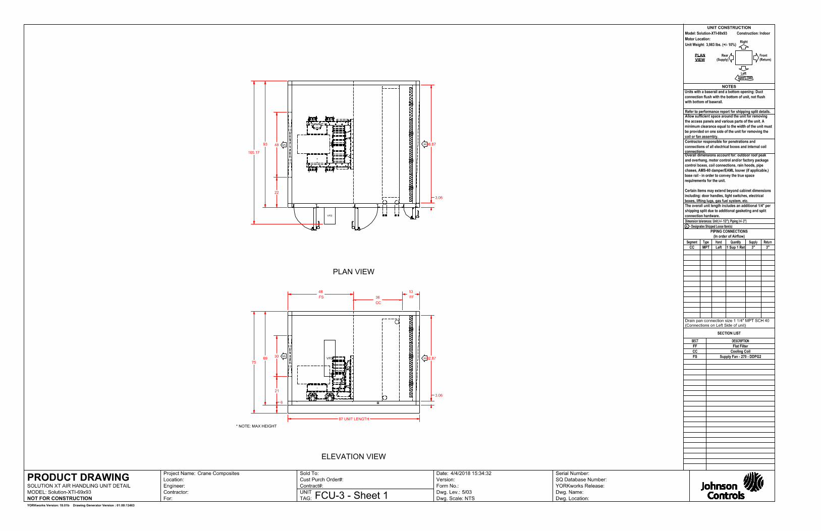
Dimension & Weights Summary
SectionLength*
(in.)Width**
(in.)Height
(in.)Weight
(lbs.)FF Flat Filter SegmentCC Variable Length Cooling Coil SegmentFS-SWSI Supply Fan Segment
133648
939393
696969
50016411842
Overall: 97 93 69 3983 *The length includes bottom tier segments only.
**The width does not include coil connection extensions or door latches that extent beyond the unit casing. The width does not include the depth of any pipe chases.
Shipping Skid Summary
Shipping SkidLength*
(in.)Width**
(in.)Height***
(in.)Weight
(lbs.)(FS-SWSI CC FF)
Ship Loose:None
97 107 79 3983
*The length includes any mounted rain-hoods, discharge flanges, tie-down brackets, shipping wood-blocks, front dampers, split connectors, electrical/control components, outrigging extensions, isolation dampers, inlet baskets
**The width includes any door handles, coil connections, drain connections, lifting lugs, mounted pipe-chases, electrical/control components, tie-down brackets, side dampers
***The height includes any base-rails, shipping wood-blocks, roof peak, discharge flanges, mounted gas-furnace flue pipes
Shipping Skid Sequence
Tier 1
(FPS < CC < FF)

SOLUTION XT AIR HANDLING UNITPERFORMANCE SPECIFICATION
Unit Tag Qty Model Air Flow (CFM)FCU-3 1 Indoor Air Handler 69 x 93 16000
Project Name: Crane Composites York Contract No.: Printed: 4/4/2018 15:42:05 FCU-3PerformanceUnit Folder: FCU-3 4/4/2018 3:34:30 PM Page 8 of 9
Sound Summary
Octave Band Sound Power Levels (dB Re. 1 picowatt)
63 125 250 500 1000 2000 4000 8000 dBADucted Discharge Rear-1, FS 91 87 92 89 87 83 80 79Return Air INLET, FF 80 80 93 82 74 71 67 62
Sound data tested in accordance with AHRI-260 (2001), Standard for Sound Rating of Ducted Air Moving and Conditioning Equipment.
Notes:1. The overall A-weighted sound power level is only applicable to sound radiation outdoors and casing radiated
sound. This metric does not apply to ducted components2. Return air sound powers are estimated using 100% of unit flow.
SOLUTION XT AIR HANDLING UNITPERFORMANCE SPECIFICATION
Unit Tag Qty Model Air Flow (CFM)FCU-3 1 Indoor Air Handler 69 x 93 16000
Project Name: Crane Composites York Contract No.: Printed: 4/4/2018 15:42:05 FCU-3PerformanceUnit Folder: FCU-3 4/4/2018 3:34:30 PM Page 9 of 9
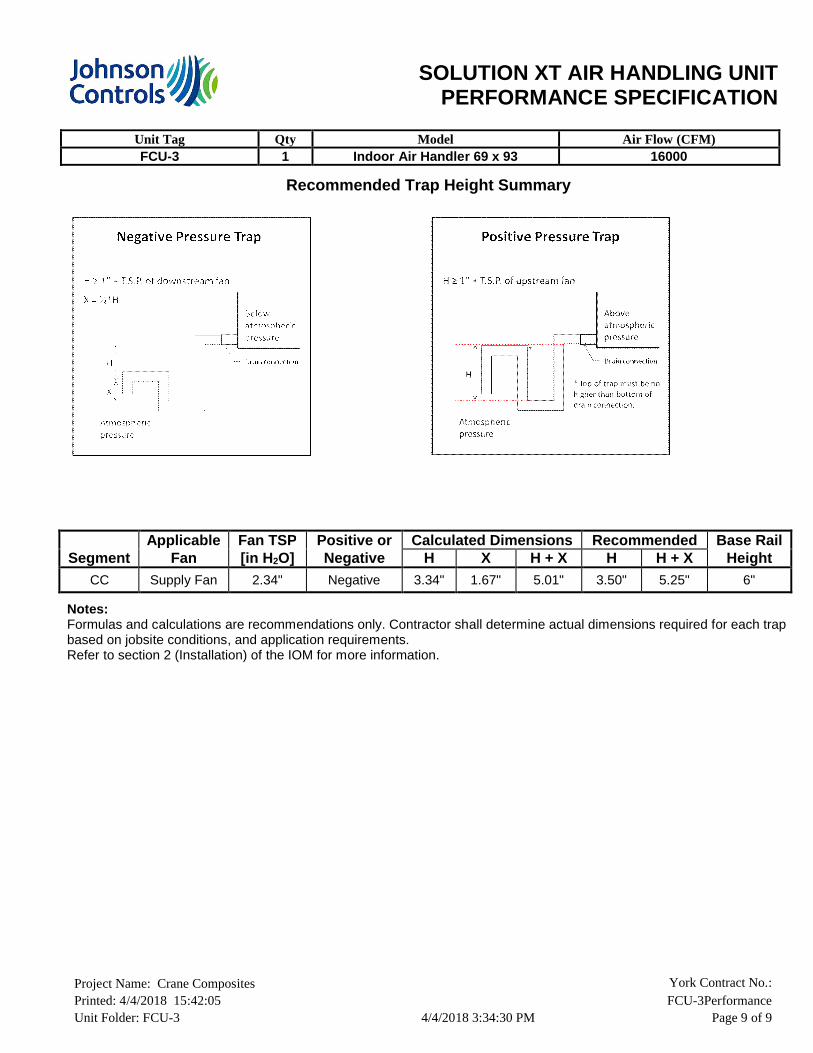
Recommended Trap Height Summary
Applicable Fan TSP Positive or Calculated Dimensions Recommended Base Rail
Segment Fan [in H2O] Negative H X H + X H H + X Height
CC Supply Fan 2.34" Negative 3.34" 1.67" 5.01" 3.50" 5.25" 6"
Notes:Formulas and calculations are recommendations only. Contractor shall determine actual dimensions required for each trap based on jobsite conditions, and application requirements.Refer to section 2 (Installation) of the IOM for more information.

SOLUTION XT AIR HANDLING UNITPERFORMANCE SPECIFICATION
Unit Tag Qty Model Air Flow (CFM)FCU-4 1 Indoor Air Handler 69 x 93 16000
Project Name: Crane Composites York Contract No.: Printed: 4/4/2018 15:42:07 FCU-4PerformanceUnit Folder: FCU-4 4/4/2018 3:35:35 PM Page 1 of 9
Unit Sequence
Tier 1 FPS <<< CC <<< FF
Basic Unit Options
Insulation Type: (Refer to Each Segment)Base Rail Height: 6" Formed Steel NON Welded
BasePerformance: High Performance
Statement of compliance of standard units.
Solution XT AHU's meet IBC seismic requirements for non-critical equipment (Ip = 1.0) for locations with design spectral response Sds <= 0.43. Units must be rigid mounted.
The anchorage of the unit to the ground or building structure needs to be evaluated by and is the responsibility of the engineer of record.
Specification of seismic requirements is the responsibility of the project design engineer. If formal certification is required, please contact your sales representative and/or application engineer for review. Certain application and site requirements may require additional cost and/or lead time.
*Note:Component locations are listed as Segment Hand (Unit Hand) : ex. Left (Right) See Submittal Drawing for additional details

SOLUTION XT AIR HANDLING UNITPERFORMANCE SPECIFICATION
Unit Tag Qty Model Air Flow (CFM)FCU-4 1 Indoor Air Handler 69 x 93 16000
Project Name: Crane Composites York Contract No.: Printed: 4/4/2018 15:42:07 FCU-4PerformanceUnit Folder: FCU-4 4/4/2018 3:35:35 PM Page 2 of 9
Segments Listed Starting At Air Inlet
FF – Flat Filter SegmentFilter Media Detail Filter Segment Options
(Quantity)Filter Sizes: (9)20x20; (3)24x20 Interior STD Ga. Galvanized Liner Insulation: R-13 2" FoamSTD Ga. Galvanized Floor LinerExterior 18 Ga. Galvanized Liner Galvanized Blankoff MaterialFilter Gauge (Magnehelic with Flag) (0 - 1 in. w. c.) (Door)Access Door on Left Side(Left) 63H x 10WMultiple Handles, No Lock, Outward OpeningOptimized Filter Arrangement
Filter Loading: SideFilter Depth: 2"Filter Media Type: Pleated 30% (MERV 8)Filter Area (ft²): 35.0Filter Air Pressure Drop (in. w.g.): 0.23Dirty Filter Allowance (in. w.g.): 0.30
Spare Filter Media:Spare Filter Quantity Set(s):
Pleated 30% (MERV 8)1
CC – Cooling Coil Segment
Coil Segment Details Coil Segment OptionsCoil Space: 13" Interior STD Ga. Galvanized Liner
Insulation: R-13 2" FoamSTD Ga. Galvanized Floor LinerExterior 18 Ga. Galvanized Liner 0" Downspout304 Stainless Steel Intermediate Pan22" IAQ Drain Pan Left (Left)Stainless SteelAccess Door on Left Side(Left) 63H x 18WMultiple Handles, No Lock, Outward OpeningInside / Outside Door HandlesBulkhead Material GalvanizedCoil Supports Galvanized

SOLUTION XT AIR HANDLING UNITPERFORMANCE SPECIFICATION
Unit Tag Qty Model Air Flow (CFM)FCU-4 1 Indoor Air Handler 69 x 93 16000
Project Name: Crane Composites York Contract No.: Printed: 4/4/2018 15:42:07 FCU-4PerformanceUnit Folder: FCU-4 4/4/2018 3:35:35 PM Page 3 of 9
FS - Supply Plenum Fan SegmentSegment Details Fan Segment Options
Segment Air Pressure Drop (in. w.g.): 0.43 1" Spring IsolatorInterior STD Ga. Galvanized Liner Insulation: R-13 2" FoamSTD Ga. Galvanized Floor LinerExterior 18 Ga. Galvanized Liner Convenience Outlet 20AFan AFMS Airflow Constant (K Factor): 4156.00Transducer Range: 0-25"Access Door on Left Side(Left) 63H x 18WMultiple Handles, No Lock, Outward OpeningInside / Outside Door Handles
Air Flow per Fan (CFM): 16000Air Flow Total (CFM): 16000Altitude (ft.): 630TSP/ESP (in. w.g.): 2.34/ 0.75Air Inlet: Front(Front)Fan Discharge: Rear-1(Rear)
Fan DetailType: PL-DDPG2Size: 270-12Construction: IIBearing Options: NoneFan RPM: 1537BHP/(Pe/kW)*: 11.13Total Fan BHP/(Pe/kW)*: 11.13Outlet Velocity (ft/min): N/A% Wheel Width: 120.00% Wheel Diameter: 100.00
Motor Detail (per motor)Motor Type: WEG TEFC Premium EfficiencyHP/kW* 15.0Voltage/Phase/Frequency: 460/3/60 HzInsulation Class: FMotor RPM: 1200Frame Size: 284Shaft Grounding RingLocation N/ADrive Type: Direct DriveBelt Drive Type: N/A
Full Load Amps (FLA): 17.90Efficiency: 91.7%

SOLUTION XT AIR HANDLING UNITPERFORMANCE SPECIFICATION
Unit Tag Qty Model Air Flow (CFM)FCU-4 1 Indoor Air Handler 69 x 93 16000
Project Name: Crane Composites York Contract No.: Printed: 4/4/2018 15:42:07 FCU-4PerformanceUnit Folder: FCU-4 4/4/2018 3:35:35 PM Page 4 of 9
Motor Control – Supply Fan
Motor Control DetailsMotor Control Type: Variable Frequency Drive
Motor Control Options EnvironmentalNon Fused DisconnectRFI/EMI EMC FilterSwinging DC Line Choke (equivalent to 5% Input Line Reactor)Modbus RTU, Johnson N2, BACnet
Ambient Temperature (°F): 5 to 104Storage Temperature (°F): -40 to 158Humidity: MAX 95% RH non-condensingAltitude: 3,280 ft. without derate (1% derate
for each additional 328 ft.)Enclosure: NEMA 1
InputRated Input Voltage: 380/400/415/440/460/480 +10% -15% VAC 3 phaseRated Input Current Amps: 23.00Heat Loss in Watts 100% Load: 337.00Efficiency (%): 98.00
OutputOutput Current Amps: 23.0Overload Current Rating: 110% for 1 minute every 10 minutes
Drives are rated for use below 3,280 ft and 104°F.Use Airmod AYK Derating Charts for use above these limits.
Copper Conductors Only

SOLUTION XT AIR HANDLING UNITPERFORMANCE SPECIFICATION
Unit Tag Qty Model Air Flow (CFM)FCU-4 1 Indoor Air Handler 69 x 93 16000
Project Name: Crane Composites York Contract No.: Printed: 4/4/2018 15:42:07 FCU-4PerformanceUnit Folder: FCU-4 4/4/2018 3:35:35 PM Page 5 of 9
Coils & Spacers Listed Starting In Direction Of Air Flow
CC Coil - 01 Coil General/Physical Details Air Side Performance Fluid Side PerformanceLocation: 0 Air Flow (acfm): 16000 EWT (°F):
LWT (°F):GPM:WPD (ft):FPS:Fluid Type:% Glycol:Fluid Weight(lb):Fluid Volume(ft³):
42.058.367.211.2
3.0Propylene
30.00303.0
4.7
Tag: AirCoil Altitude (ft.): 630Application: Cooling EAT-DB (°F): 80.0Coil Type: Glycol EAT-WB (°F): 67.0Face Type: Full LAT-DB (°F): 57.0Tube Diameter: 5/8" FDW LAT-WB (°F): 56.2
Tube Material: Copper FV (ft/min): 505Tube Wall Thickness: .020" SMBH: 384.7Fouling Factor (hft²°F/btu): 0.00000 TMBH: 520.2Fin Type: Flat APD (in. w.g.): 0.63Fin Thickness: .010" Fin Material: AluminumCasing Material: GalvanizedConnection Material: SteelConnection Type: MPTCoating: None
Rows: 8Fins Per Inch: 10
Tubes Per Circuit: 12Finned Height (in.): 57.00Finned Length (in.): 80Coil Face Area (ft²): 31.7Coil Conn. Loc.: Left(Left)Supp Conn Size:Rtn Conn Size:Supply Conn.(per coil):
3"3"1
Ratings are for coils manufactured by Johnson Controls, Inc., 507 E. Michigan St., Milwaukee WI 53202.
FDW Tube Spacing: 1.50" x 1.30"
AHRI Messages:This coil is not certified by AHRI 410. This coil is rated in accordance with the AHRI Forced-Circulation Air-Cooling and Air-Heating Coils Certification program which is based on AHRI Standard 410. Certified units may be found in the AHRI Directory at www.ahridirectory.org.
Coil Dll Version: 7.5b.003
Electrical Circuit Summary
Short-Circuit Summary

SOLUTION XT AIR HANDLING UNITPERFORMANCE SPECIFICATION
Unit Tag Qty Model Air Flow (CFM)FCU-4 1 Indoor Air Handler 69 x 93 16000
Project Name: Crane Composites York Contract No.: Printed: 4/4/2018 15:42:07 FCU-4PerformanceUnit Folder: FCU-4 4/4/2018 3:35:35 PM Page 6 of 9
5 kA rms Symmetrical 480 V Maximum
Circuit 1 Circuit 1 Electrical DetailsSupply Fan Motor Control Full Load Amps (FLA): 17.9
Minimum Circuit Ampacity (MCA): 22.4Maximum Overcurrent Protection: 40.00
Circuit 2 Circuit 2 Electrical DetailsLights and Outlets
Maximum Overcurrent Protection: 20.00
Static Pressure Summary
Segment Component Supply (in.
w.g.)
Return Fan
(in. w.g.)
FF Flat Filter
CC Variable Length Cooling CoilFS-SWSI Supply Fan
2" Pleated 30% (MERV 8)Dirty Filter AllowanceCooling 8 rows 10 finsOpening Pressure DropExternal Static Pressure - User Entered Pressure Drop
0.230.300.630.430.75
Total 2.34 0.00
Air handling unit parameters vary depending on conditions. Parameters such as airflows, air pressure drops, and coil capacities are shown for design conditions.

SOLUTION XT AIR HANDLING UNITPERFORMANCE SPECIFICATION
Unit Tag Qty Model Air Flow (CFM)FCU-4 1 Indoor Air Handler 69 x 93 16000
Project Name: Crane Composites York Contract No.: Printed: 4/4/2018 15:42:07 FCU-4PerformanceUnit Folder: FCU-4 4/4/2018 3:35:35 PM Page 7 of 9
Dimension & Weights Summary
SectionLength*
(in.)Width**
(in.)Height
(in.)Weight
(lbs.)FF Flat Filter SegmentCC Variable Length Cooling Coil SegmentFS-SWSI Supply Fan Segment
133648
939393
696969
50016411842
Overall: 97 93 69 3983 *The length includes bottom tier segments only.
**The width does not include coil connection extensions or door latches that extent beyond the unit casing. The width does not include the depth of any pipe chases.
Shipping Skid Summary
Shipping SkidLength*
(in.)Width**
(in.)Height***
(in.)Weight
(lbs.)(FS-SWSI CC FF)
Ship Loose:None
97 107 79 3983
*The length includes any mounted rain-hoods, discharge flanges, tie-down brackets, shipping wood-blocks, front dampers, split connectors, electrical/control components, outrigging extensions, isolation dampers, inlet baskets
**The width includes any door handles, coil connections, drain connections, lifting lugs, mounted pipe-chases, electrical/control components, tie-down brackets, side dampers
***The height includes any base-rails, shipping wood-blocks, roof peak, discharge flanges, mounted gas-furnace flue pipes
Shipping Skid Sequence
Tier 1
(FPS < CC < FF)
SOLUTION XT AIR HANDLING UNITPERFORMANCE SPECIFICATION
Unit Tag Qty Model Air Flow (CFM)FCU-4 1 Indoor Air Handler 69 x 93 16000
Project Name: Crane Composites York Contract No.: Printed: 4/4/2018 15:42:07 FCU-4PerformanceUnit Folder: FCU-4 4/4/2018 3:35:35 PM Page 8 of 9
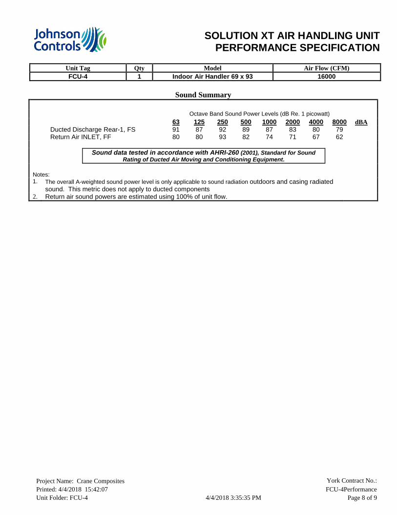
Sound Summary
Octave Band Sound Power Levels (dB Re. 1 picowatt)
63 125 250 500 1000 2000 4000 8000 dBADucted Discharge Rear-1, FS 91 87 92 89 87 83 80 79Return Air INLET, FF 80 80 93 82 74 71 67 62
Sound data tested in accordance with AHRI-260 (2001), Standard for Sound Rating of Ducted Air Moving and Conditioning Equipment.
Notes:1. The overall A-weighted sound power level is only applicable to sound radiation outdoors and casing radiated
sound. This metric does not apply to ducted components2. Return air sound powers are estimated using 100% of unit flow.

SOLUTION XT AIR HANDLING UNITPERFORMANCE SPECIFICATION
Unit Tag Qty Model Air Flow (CFM)FCU-4 1 Indoor Air Handler 69 x 93 16000
Project Name: Crane Composites York Contract No.: Printed: 4/4/2018 15:42:07 FCU-4PerformanceUnit Folder: FCU-4 4/4/2018 3:35:35 PM Page 9 of 9
Recommended Trap Height Summary
Applicable Fan TSP Positive or Calculated Dimensions Recommended Base Rail
Segment Fan [in H2O] Negative H X H + X H H + X Height
CC Supply Fan 2.34" Negative 3.34" 1.67" 5.01" 3.50" 5.25" 6"
Notes:Formulas and calculations are recommendations only. Contractor shall determine actual dimensions required for each trap based on jobsite conditions, and application requirements.Refer to section 2 (Installation) of the IOM for more information.
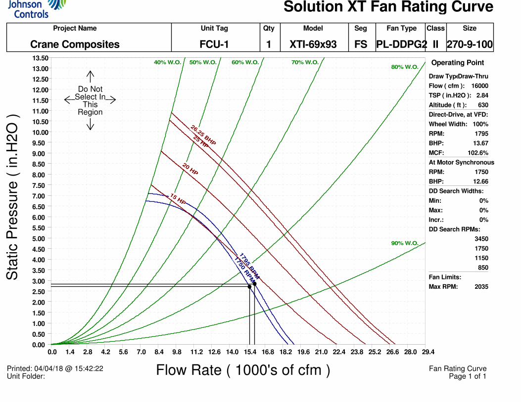
Solution XT Fan Rating Curve
Project Name Unit Tag Qty Model Seg Fan Type Class Size
Crane Composites FCU-1 1 XTI-69x93 FS PL-DDPG2 II 270-9-100
Operating Point
Draw Type:Draw-Thru
Flow ( cfm ): 16000
TSP ( in.H2O ): 2.84
Altitude ( ft ): 630
Direct-Drive, at VFD:
Wheel Width: 100%
RPM: 1795
BHP: 13.67
MCF: 102.6%
At Motor Synchronous:
RPM: 1750
BHP: 12.66
DD Search Widths:
Min: 0%
Max: 0%
Incr.: 0%
DD Search RPMs:
3450
1750
1150
850
Fan Limits:
Max RPM: 2035
Unit Folder: Printed: 04/04/18 @ 15:42:22
Page 1 of 1Fan Rating Curve
Do NotSelect In
ThisRegion
Flow Rate ( 1000's of cfm )
0.0 1.4 2.8 4.2 5.6 7.0 8.4 9.8 11.2 12.6 14.0 15.4 16.8 18.2 19.6 21.0 22.4 23.8 25.2 26.6 28.0 29.4
Sta
tic P
ressure
( in.H
2O
)
0.00
0.50
1.00
1.50
2.00
2.50
3.00
3.50
4.00
4.50
5.00
5.50
6.00
6.50
7.00
7.50
8.00
8.50
9.00
9.50
10.00
10.50
11.00
11.50
12.00
12.50
13.00
13.5040% W.O. 50% W.O. 60% W.O. 70% W.O.
80% W.O.
90% W.O.
1795 R
PM
1750 R
PM
15 HP
20 HP
25 HP
26.25 BH
P

Solution XT Fan Rating Curve
Project Name Unit Tag Qty Model Seg Fan Type Class Size
Crane Composites FCU-2 1 XTI-69x93 FS PL-DDPG2 II 270-9-100
Operating Point
Draw Type:Draw-Thru
Flow ( cfm ): 16000
TSP ( in.H2O ): 2.84
Altitude ( ft ): 630
Direct-Drive, at VFD:
Wheel Width: 100%
RPM: 1795
BHP: 13.67
MCF: 102.6%
At Motor Synchronous:
RPM: 1750
BHP: 12.66
DD Search Widths:
Min: 0%
Max: 0%
Incr.: 0%
DD Search RPMs:
3450
1750
1150
850
Fan Limits:
Max RPM: 2035
Unit Folder: Printed: 04/04/18 @ 15:43:01
Page 1 of 1Fan Rating Curve
Do NotSelect In
ThisRegion
Flow Rate ( 1000's of cfm )
0.0 1.4 2.8 4.2 5.6 7.0 8.4 9.8 11.2 12.6 14.0 15.4 16.8 18.2 19.6 21.0 22.4 23.8 25.2 26.6 28.0 29.4
Sta
tic P
ressure
( in.H
2O
)
0.00
0.50
1.00
1.50
2.00
2.50
3.00
3.50
4.00
4.50
5.00
5.50
6.00
6.50
7.00
7.50
8.00
8.50
9.00
9.50
10.00
10.50
11.00
11.50
12.00
12.50
13.00
13.5040% W.O. 50% W.O. 60% W.O. 70% W.O.
80% W.O.
90% W.O.
1795 R
PM
1750 R
PM
15 HP
20 HP
25 HP
26.25 BH
P

Solution XT Fan Rating Curve
Project Name Unit Tag Qty Model Seg Fan Type Class Size
Crane Composites FCU-3 1 XTI-69x93 FS PL-DDPG2 II 270-12-120
Operating Point
Draw Type:Draw-Thru
Flow ( cfm ): 16000
TSP ( in.H2O ): 2.34
Altitude ( ft ): 630
Direct-Drive, at VFD:
Wheel Width: 120%
RPM: 1536
BHP: 11.13
MCF: 133.6%
At Motor Synchronous:
RPM: 1150
BHP: 4.67
DD Search Widths:
Min: 0%
Max: 0%
Incr.: 0%
DD Search RPMs:
3450
1750
1150
850
Fan Limits:
Max RPM: 2035
Unit Folder: Printed: 04/04/18 @ 15:43:14
Page 1 of 1Fan Rating Curve
Do NotSelect In
ThisRegion
Flow Rate ( 1000's of cfm )
0.0 1.4 2.8 4.2 5.6 7.0 8.4 9.8 11.2 12.6 14.0 15.4 16.8 18.2 19.6 21.0 22.4 23.8 25.2 26.6 28.0 29.4
Sta
tic P
ressure
( in.H
2O
)
0.00
0.50
1.00
1.50
2.00
2.50
3.00
3.50
4.00
4.50
5.00
5.50
6.00
6.50
7.00
7.50
8.00
8.50
9.00
9.50
10.00
10.50
11.00
11.50
12.0040% W.O. 50% W.O. 60% W.O. 70% W.O.
80% W.O.
90% W.O.
1536 R
PM
1150 RPM
10 HP
15 HP
20 HP
25 HP
26.25 BHP

Solution XT Fan Rating Curve
Project Name Unit Tag Qty Model Seg Fan Type Class Size
Crane Composites FCU-4 1 XTI-69x93 FS PL-DDPG2 II 270-12-120
Operating Point
Draw Type:Draw-Thru
Flow ( cfm ): 16000
TSP ( in.H2O ): 2.34
Altitude ( ft ): 630
Direct-Drive, at VFD:
Wheel Width: 120%
RPM: 1536
BHP: 11.13
MCF: 133.6%
At Motor Synchronous:
RPM: 1150
BHP: 4.67
DD Search Widths:
Min: 0%
Max: 0%
Incr.: 0%
DD Search RPMs:
3450
1750
1150
850
Fan Limits:
Max RPM: 2035
Unit Folder: Printed: 04/04/18 @ 15:43:34
Page 1 of 1Fan Rating Curve
Do NotSelect In
ThisRegion
Flow Rate ( 1000's of cfm )
0.0 1.4 2.8 4.2 5.6 7.0 8.4 9.8 11.2 12.6 14.0 15.4 16.8 18.2 19.6 21.0 22.4 23.8 25.2 26.6 28.0 29.4
Sta
tic P
ressure
( in.H
2O
)
0.00
0.50
1.00
1.50
2.00
2.50
3.00
3.50
4.00
4.50
5.00
5.50
6.00
6.50
7.00
7.50
8.00
8.50
9.00
9.50
10.00
10.50
11.00
11.50
12.0040% W.O. 50% W.O. 60% W.O. 70% W.O.
80% W.O.
90% W.O.
1536 R
PM
1150 RPM
10 HP
15 HP
20 HP
25 HP
26.25 BHP

DATA SHEETThree Phase Induction Motor - Squirrel Cage
Customer :
____
Rev. Changes Summary Performed Checked Date
Performed by
Checked by Page Revision
Date 04/04/2018 1 / 1This document is exclusive property of WEG S/A. Reprinting is not allowed without written authorization of WEG S/A.
Subject to change without notice
Product line : W22 NEMA Premium EfficiencyThree-Phase
Product code : 11723921
Catalog # : 01518ET3E254T-W22
FrameOutputPolesFrequencyRated voltageRated currentL. R. AmperesLRCNo load currentRated speedSlipRated torqueLocked rotor torqueBreakdown torqueInsulation classService factorMoment of inertia (J)Design
: 254/6T: 15 HP (11 kW): 4: 60 Hz: 208-230/460 V: 39.8-36.0/18.0 A: 255-230/115 A: 6.4x(Code G): 13.8-16.0/8.00 A: 1765 rpm: 1.94 %: 44.0 ft.lb: 229 %: 270 %: F: 1.25: 2.62 sq.ft.lb: B
Locked rotor timeTemperature riseDuty cycleAmbient temperatureAltitudeProtection degreeCooling methodMountingRotation¹Noise level²Starting methodApprox. weight³
: 30s (cold) 17s (hot): 80 K: Cont.(S1): -20°C to +40°C: 1000 m.a.s.l.: IP55: IC411 - TEFC: F-1: Both (CW and CCW): 64.0 dB(A): Direct On Line: 312 lb
Output 50% 75% 100% Foundation loadsEfficiency (%) 91.0 91.7 92.4 Max. traction : 491 lbPower Factor 0.68 0.78 0.83 Max. compression : 803 lb
Drive end Non drive endBearing type : 6309 C3 6209 C3Sealing : V'Ring V'RingLubrication interval : 20000 h 20000 hLubricant amount : 13 g 9 gLubricant type : Mobil Polyrex EM
Notes
This revision replaces and cancel the previous one, whichmust be eliminated.(1) Looking the motor from the shaft end.(2) Measured at 1m and with tolerance of +3dB(A).(3) Approximate weight subject to changes aftermanufacturing process.(4) At 100% of full load.
These are average values based on tests with sinusoidalpower supply, subject to the tolerances stipulated in NEMAMG-1.
FCU-1, 2
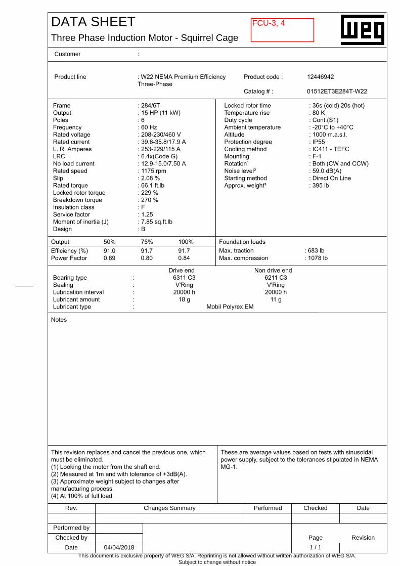
DATA SHEETThree Phase Induction Motor - Squirrel Cage
Customer :
____
Rev. Changes Summary Performed Checked Date
Performed by
Checked by Page Revision
Date 04/04/2018 1 / 1This document is exclusive property of WEG S/A. Reprinting is not allowed without written authorization of WEG S/A.
Subject to change without notice
Product line : W22 NEMA Premium EfficiencyThree-Phase
Product code : 12446942
Catalog # : 01512ET3E284T-W22
FrameOutputPolesFrequencyRated voltageRated currentL. R. AmperesLRCNo load currentRated speedSlipRated torqueLocked rotor torqueBreakdown torqueInsulation classService factorMoment of inertia (J)Design
: 284/6T: 15 HP (11 kW): 6: 60 Hz: 208-230/460 V: 39.6-35.8/17.9 A: 253-229/115 A: 6.4x(Code G): 12.9-15.0/7.50 A: 1175 rpm: 2.08 %: 66.1 ft.lb: 229 %: 270 %: F: 1.25: 7.85 sq.ft.lb: B
Locked rotor timeTemperature riseDuty cycleAmbient temperatureAltitudeProtection degreeCooling methodMountingRotation¹Noise level²Starting methodApprox. weight³
: 36s (cold) 20s (hot): 80 K: Cont.(S1): -20°C to +40°C: 1000 m.a.s.l.: IP55: IC411 - TEFC: F-1: Both (CW and CCW): 59.0 dB(A): Direct On Line: 395 lb
Output 50% 75% 100% Foundation loadsEfficiency (%) 91.0 91.7 91.7 Max. traction : 683 lbPower Factor 0.69 0.80 0.84 Max. compression : 1078 lb
Drive end Non drive endBearing type : 6311 C3 6211 C3Sealing : V'Ring V'RingLubrication interval : 20000 h 20000 hLubricant amount : 18 g 11 gLubricant type : Mobil Polyrex EM
Notes
This revision replaces and cancel the previous one, whichmust be eliminated.(1) Looking the motor from the shaft end.(2) Measured at 1m and with tolerance of +3dB(A).(3) Approximate weight subject to changes aftermanufacturing process.(4) At 100% of full load.
These are average values based on tests with sinusoidalpower supply, subject to the tolerances stipulated in NEMAMG-1.
FCU-3, 4


SAI: Move 48x30SA opening as lowas possible on unit(5" from bottom ofunit as discussedwith GlacierGroup). Unit open-ing size to remainthe same. FCU-04only.


FCU-1-4
SAI: Convenience recep-tacle not required.
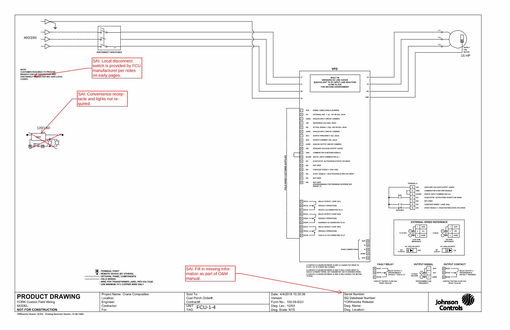
460/3/60
120/1/60
15 HP
FCU-1-4
SAI: Convenience recep-tacle and lights not re-quired.
SAI: Local disconnect switch is provided by FCU manufacturer per notes on early pages.
SAI: Fill in missing infor-mation as part of O&Mmanual.
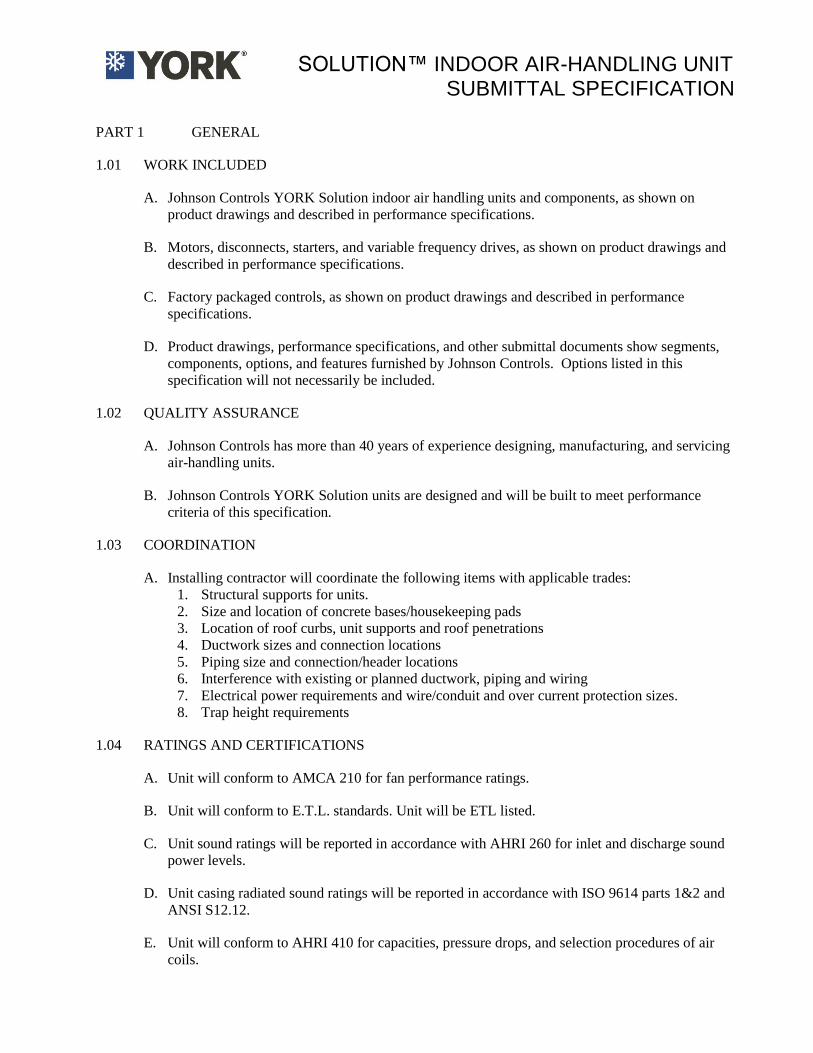
SOLUTION™ INDOOR AIR-HANDLING UNIT
SUBMITTAL SPECIFICATION
PART 1 GENERAL
1.01 WORK INCLUDED
A. Johnson Controls YORK Solution indoor air handling units and components, as shown on
product drawings and described in performance specifications.
B. Motors, disconnects, starters, and variable frequency drives, as shown on product drawings and
described in performance specifications.
C. Factory packaged controls, as shown on product drawings and described in performance
specifications.
D. Product drawings, performance specifications, and other submittal documents show segments,
components, options, and features furnished by Johnson Controls. Options listed in this
specification will not necessarily be included.
1.02 QUALITY ASSURANCE
A. Johnson Controls has more than 40 years of experience designing, manufacturing, and servicing
air-handling units.
B. Johnson Controls YORK Solution units are designed and will be built to meet performance
criteria of this specification.
1.03 COORDINATION
A. Installing contractor will coordinate the following items with applicable trades:
1. Structural supports for units.
2. Size and location of concrete bases/housekeeping pads
3. Location of roof curbs, unit supports and roof penetrations
4. Ductwork sizes and connection locations
5. Piping size and connection/header locations
6. Interference with existing or planned ductwork, piping and wiring
7. Electrical power requirements and wire/conduit and over current protection sizes.
8. Trap height requirements
1.04 RATINGS AND CERTIFICATIONS
A. Unit will conform to AMCA 210 for fan performance ratings.
B. Unit will conform to E.T.L. standards. Unit will be ETL listed.
C. Unit sound ratings will be reported in accordance with AHRI 260 for inlet and discharge sound
power levels.
D. Unit casing radiated sound ratings will be reported in accordance with ISO 9614 parts 1&2 and
ANSI S12.12.
E. Unit will conform to AHRI 410 for capacities, pressure drops, and selection procedures of air
coils.

Filename: SPEC_XTIrtf Page 2 of 7
F. Unit will conform to ANSI/AHRI 430 for all fabrication procedures of air handling units.
G. Motors covered by the Federal Energy Policy Act (EPACT) will meet EPACT requirements.
H. Damper performance will comply with AMCA 500.
I. Airflow Monitoring Stations will be rated in accordance with AMCA 611-95 and bear a Certified
Ratings Seal for Airflow Measurement Performance.
J. Air-handling units will be ISO 9001 certified.
K. Air-handling units will be manufactured in an ISO 9002 certified facility.
1.05 DELIVERY
A. Unpainted units will be shrink-wrapped for protection during shipment. Painted units will be
tarped for protection during shipment.
B. Openings will be protected against damage during shipping
C. Loose-shipped items will be packed, protected and secured with units. Detailed packing list of
loose-shipped items, illustrations and instructions for application will be included.
1.06 WARRANTY
A. Johnson Controls will warranty unit and factory packaged controls for eighteen (18) months from
date of shipment or twelve (12) months from startup (whichever occurs first). Warranty will be
limited to manufacturer’s defects on parts. Warranty does not include parts associated with
routine maintenance, such as belts, air filters, etc. Warranty work shall be performed by
manufacturer’s factory-trained and factory-employed technician. Warranty does not extend to
alterations, modifications, or external components installed after unit is shipped.
PART 2 PRODUCTS
2.01 GENERAL DESCRIPTION
A. Johnson Controls YORK Solution air-handling units are designed and built to meet performance
detailed in this submittal.
B. Unit will be complete with fans, motors, coils, dampers, controls, access doors and other
components/options, as shown on product drawings, wiring diagrams, and as described in
performance specifications.
C. Fans and drives will be balanced to limit vibration at operating speeds.
D. Unit will ship in one (1) piece whenever possible. Shipping splits will be provided when
necessary. Lifting lugs will be provided where required for proper lifting.
E. Unit casing will be factory insulated.
F. Units will be ETL labeled.

Filename: SPEC_XTIrtf Page 3 of 7
2.02 BASE RAIL
A. Structural base rail will be provided under the full perimeter of the unit, formed from mill
galvanized steel
2.03 UNIT CASING
A. Johnson Controls YORK Solution unit is specifically designed for indoor applications.
B. Unit casing will consist of a structural frame and insulated roof, wall, and floor panels.
C. Removal of wall panels will not affect structural integrity of units.
D. Unit casing will be insulated with spray injected foam to achieve a minimum thermal resistance
of R13 hr-ft2-°F/BTU. Insulation application will meet the requirements of NFPA 90A
E. Insulation system will be resistant to mold growth in accordance with a standardized test
method such as UL 181 or ASTM C 1338
F. Unit will conform to ASHRAE Standard 111 Class 6 for casing leakage no more than 1% of
design airflow at 1.25 times design static pressure up to a maximum of +8 inches w.g. in
positive pressure sections and -8 inches w.g. in negative pressure sections.
G. Wall panels and access doors will deflect no more than L/240 when subjected to 1.5 times
design static pressure up to a maximum of +8 inches w.g. in positive pressure sections and -8
inches w.g. in negative pressure sections. ‘L’ is the panel-span length and ‘L/240’ is the
deflection at panel midpoint.
H. Unit will have double wall, 2” insulated panels for walls, roof, and floor. Exterior skin will be
galvanized sheet steel. Individual segments will have galvanized sheet steel, stainless sheet
steel, or perforated galvanized interior liner, as described in performance specifications.
1. Provide panels with optional perforated liner in the fan section and other sections as shown
on the drawings. Interior liner will be perforated galvanized. Minimum perforated panel
thermal resistance (R-Value) will be R11 hr-ft2-°F/BTU.
I. Floor panels will be double wall construction, designed to provide at most L/240 deflection
when subjected to a 300 lb. load at mid-span.
J. Double wall access doors will be provided on sections as shown on product drawings.
1. Stainless steel hinges permit a 180 door swing.
2. Access door will be of the same material type as exterior/interior casing.
3. Access door latches will use a roller cam latching mechanism.
K. View ports will be double-pane tempered glass.
2.04 DRAIN PANS
A. Primary and auxiliary drain pans will be double wall with an insulation R-value of 6.25 hr-ft2-
°F/(BTU-in).

Filename: SPEC_XTIrtf Page 4 of 7
B. Drain pans comply with the guidelines of ASHRAE 62.
1. Drain pans will be double sloped at least 1/8” per foot, and have no horizontal surfaces.
2. Drain connection material will be the same as drain pan.
3. Drain pans drain to one point.
4. Drain connections will be welded to drain pans
5. Drain pans will have at least 1” clearance between pan and coil supports.
2.05 FANS
A. Fans will provide CFM and static pressure, as shown in performance specifications.
B. Fans will be Class I, II, or III, as required to meet selected RPM and horsepower shown in
performance specifications.
C. Fans will be DWDI (housed) or SWSI (plenum), as shown on product drawings.
D. Fans will have airfoil blades, as shown in performance specifications.
E. Airfoil fans will bear the AMCA Seal. Airfoil fan performance will be based on tests in
accordance with AMCA standard 210 and will comply with the requirements of AMCA
certified ratings programs for air and sound. Airfoil wheels will comply with AMCA standards
99-2408-69 and 99-2401-82.
F. Fans shafts will be polished steel and sized such that the first critical speed will be at least 125%
of the maximum operating speed for the fan pressure class. Shaft will be coated with an anti-
corrosion coating.
G. Fan and motor assembly will be internally mounted on a common base. Fan and motor base will
be spring isolated on a full width isolator support channel.
1. Fan motor will be on an adjustable base.
2. Fan discharge will be connected to cabinet via a flexible connection.
3. Access doors will be provided as shown on product drawing.
2.06 BEARINGS AND DRIVES
A. Fan bearings will have average life (L50) of at least 200,000 hours. Bearing fatigue life ratings
will comply with ANSI/AFBMA 9.
B. DWDI fans will be belt-driven. SWSI fans will be belt driven or direct driven, as shown on
product drawings.
C. Re-greaseable fan bearings will be factory lubricated and equipped with standard hydraulic
grease fittings and lube lines extended to the motor side of the fan. Fan drives will be selected
for a 1.5 service factor and will be furnished with anti-static belts.
1. Drives 15 hp or smaller on constant volume fans will be adjustable pitch.
2. Drives 20 hp or larger or drives on fans with VFDs will be fixed pitch.
3. Sheaves will be machined from close grain cast iron and statically balanced.
4. Drive belts will be V type, precision molded, raw edge construction, anti-static, oil and heat
resistant.

Filename: SPEC_XTIrtf Page 5 of 7
2.07 ELECTRICAL MOTORS
A. Fan motors will be built in accordance with the latest NEMA and IEEE standards.
B. Fan motors comply with ASHRAE Standard 90.1.
C. Fan motors will be furnished in sizes, electrical power and starting characteristics as shown in
performance specifications.
1. Fan motors will be rated for continuous, full load duty at 104F (40C) ambient temperature
and 1.15 service factor.
a. Exception: 1.5 hp and 3 hp, dual voltage (230/460V), 900 RPM, TEFC motors will have a
1.0 service factor.
2. Fan motors will be NEMA design ball bearing type.
a. Direct drive plenum fans will be coupled with motors that closely match required fan
RPM.
3. Fan motors will be Open drip proof (ODP) or totally enclosed, fan cooled (TEFC)
4. Premium Efficiency Inverter ready per NEMA STD MG1 PART 31.4.4.2
5. Motors will be suitable for use with variable frequency drives, per NEMA MG-1 Part 30.
2.08 FAN VARIABLE FREQUENCY DRIVES
1. To follow
2.09 Johnson Controls MANUFACTURED HEATING AND COOLING COILS
A. Johnson Controls manufactured coils described in this specification will not include:
1. Electric Heat coils
2. Integral face and bypass coils
3. Heat pipe coils
B. Water, direct expansion (DX), and steam coil capacity and pressure drop performance will be
certified in accordance with AHRI Standard 410, when selected within fluid velocity, inlet fluid
temperature, and entering air temperature ranges specified by AHRI 410.
C. Cooling coil segments will have a full-width IAQ drain pan that extends at least 6” downstream
of the last coil in the section.
D. Coils will be removable from the side of unit, via removable AHU panels. No more than one
panel must be removed to remove a coil.
E. Coils will have frames constructed of galvanized steel. Casing channels will be free-draining and
do not block fin area.
F. Optional Units with multiple stacked coils, will have a G-90 steel stacking rack to allow
individual coils to be removed from side of unit without disturbing any other coils. Coil pull
panels will be easily removable with no special tools. Coils will be removable from the side of
the unit.
G. Cooling coils with finned height greater than 48” will have an intermediate drain pan with
downspout to drain condensate to main drain pan. Intermediate drain pan material will match coil
frame material.
H. Coil segment door clearances will allow for at least 2-inches of field installed piping insulation.
Filename: SPEC_XTIrtf Page 6 of 7
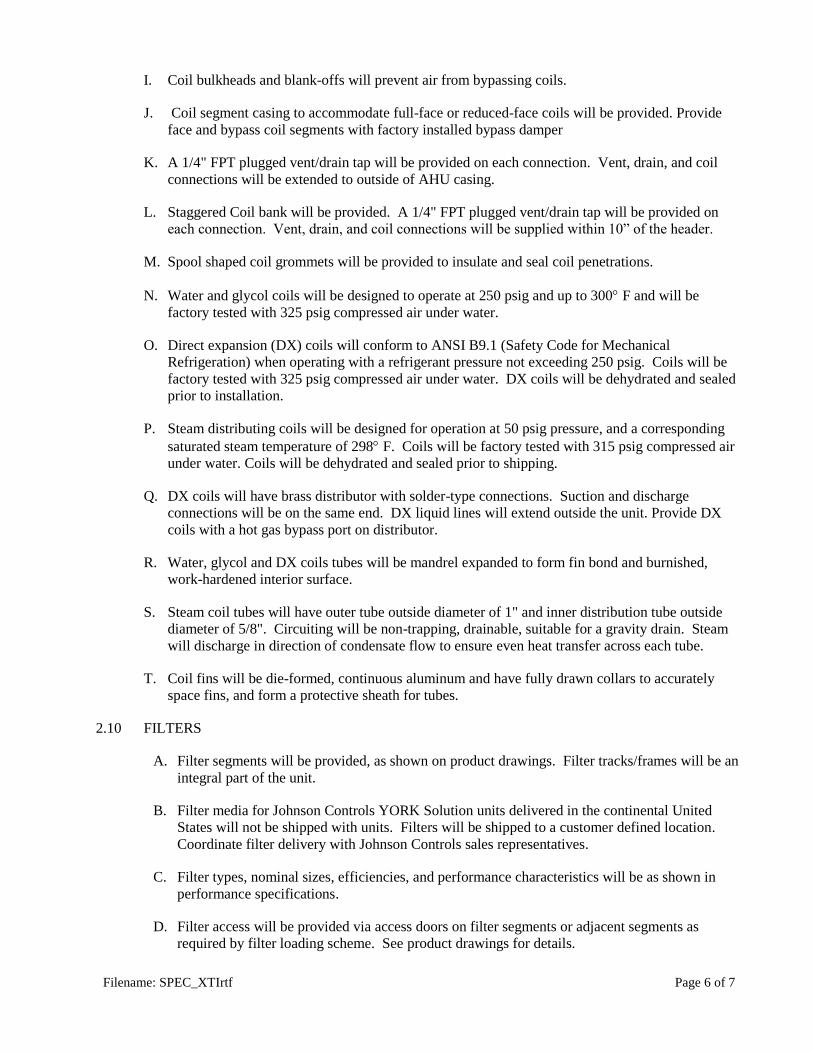
I. Coil bulkheads and blank-offs will prevent air from bypassing coils.
J. Coil segment casing to accommodate full-face or reduced-face coils will be provided. Provide
face and bypass coil segments with factory installed bypass damper
K. A 1/4" FPT plugged vent/drain tap will be provided on each connection. Vent, drain, and coil
connections will be extended to outside of AHU casing.
L. Staggered Coil bank will be provided. A 1/4" FPT plugged vent/drain tap will be provided on
each connection. Vent, drain, and coil connections will be supplied within 10” of the header.
M. Spool shaped coil grommets will be provided to insulate and seal coil penetrations.
N. Water and glycol coils will be designed to operate at 250 psig and up to 300 F and will be
factory tested with 325 psig compressed air under water.
O. Direct expansion (DX) coils will conform to ANSI B9.1 (Safety Code for Mechanical
Refrigeration) when operating with a refrigerant pressure not exceeding 250 psig. Coils will be
factory tested with 325 psig compressed air under water. DX coils will be dehydrated and sealed
prior to installation.
P. Steam distributing coils will be designed for operation at 50 psig pressure, and a corresponding
saturated steam temperature of 298 F. Coils will be factory tested with 315 psig compressed air
under water. Coils will be dehydrated and sealed prior to shipping.
Q. DX coils will have brass distributor with solder-type connections. Suction and discharge
connections will be on the same end. DX liquid lines will extend outside the unit. Provide DX
coils with a hot gas bypass port on distributor.
R. Water, glycol and DX coils tubes will be mandrel expanded to form fin bond and burnished,
work-hardened interior surface.
S. Steam coil tubes will have outer tube outside diameter of 1" and inner distribution tube outside
diameter of 5/8". Circuiting will be non-trapping, drainable, suitable for a gravity drain. Steam
will discharge in direction of condensate flow to ensure even heat transfer across each tube.
T. Coil fins will be die-formed, continuous aluminum and have fully drawn collars to accurately
space fins, and form a protective sheath for tubes.
2.10 FILTERS
A. Filter segments will be provided, as shown on product drawings. Filter tracks/frames will be an
integral part of the unit.
B. Filter media for Johnson Controls YORK Solution units delivered in the continental United
States will not be shipped with units. Filters will be shipped to a customer defined location.
Coordinate filter delivery with Johnson Controls sales representatives.
C. Filter types, nominal sizes, efficiencies, and performance characteristics will be as shown in
performance specifications.
D. Filter access will be provided via access doors on filter segments or adjacent segments as
required by filter loading scheme. See product drawings for details.

Filename: SPEC_XTIrtf Page 7 of 7
E. Performance of installed HEPA filtration systems is certified via a DOP test and classified as
UL Class 1 when tested in accordance with UL Standard 586.
F. Flush mounted, factory installed differential pressure gauge on the drive side of unit to measure
pressure drop across filters will be provided.
2.11 FINISHES
A. External unit surfaces will be factory cleaned prior to finishing or shipping.
B. Unpainted air-handling units constructed of galvanized steel will pass the ASTM B-117 test for
220-hour salt spray solution (5%) without any sign of red rust.
C. Unit will be painted, as shown in performance specifications.
1. Painted units will be prime-coated prior to painting.
2. Paint will be acrylic polyurethane.
3. Painted unit will exceed 500-hour salt spray test, with (5%) solution, without any sign of
red rust when tested in accordance with ASTM B-117.
2.12 TESTS AND INSPECTIONS
A. Fan skid will be run-balanced at specified speed to insure smooth operation.
1. Constant volume fan assemblies will be balanced at design RPM.
2. Variable volume fan assemblies will be balanced from 10% to 100% of design RPM.
3. Filter-in measurements will be taken in horizontal and vertical axes on drive and opposite-
drive sides of fan shafts.
4. Constant speed fan vibration limits: filter-in measurements will not exceed 4 mils.
5. Variable speed fan vibration limits: filter -in measurements will not exceed 7 mils.
B. Unit wiring with voltage greater than 30VAC will be hipot tested prior to shipping.

Guide Specification for Johnson Controls / ABB AYK 550 Variable Frequency Drives Section 15172
Page - 1 of 6
PART 1-GENERAL
1.01 DESCRIPTION
A. This specification is to cover a complete Variable Frequency motor Drive (VFD) consisting of a
pulse width modulated (PWM) inverter designed for use on a standard NEMA Design B induction motor. It is required that the drive manufacturer have an existing:
1. Sales representative exclusively for HVAC products, with expertise in HVAC systems and controls.
2. An independent service organization.
B. The drive manufacturer shall supply the drive and all necessary controls as herein specified. The
manufacturer shall have been engaged in the production of this type of equipment for a minimum of twenty years.
1.02 QUALITY ASSURANCE
A. Referenced Standards:
1. Institute of Electrical and Electronic Engineers (IEEE) a) Standard 519-1992, IEEE Guide for Harmonic Content and Control.
2. Underwriters laboratories a) UL508C b) UL508A
3. National Electrical Manufacturer’s Association (NEMA) a) ICS 7.0, AC Variable Speed Drives
4. IEC 16800 Parts 1 and 2 5. International Building Code (IBC) (Applies to Base Drive Only)
a) IBC 2006 Seismic - referencing ASC 7-05 and ICC AC-156
B. Qualifications:
1. VFDs and options shall be UL listed as a complete assembly. VFD’s that require the customer to supply external fuses for the VFD to be UL listed are not acceptable. The base VFD shall be UL listed for 100 KAIC at 480VAC max without the need for input fuses.
a) The VFD shall have an option for a non-fused disconnect switch with a pad lockable handle UL type 1 enclosed with a coordinated package with stand rating of 100 KAIC at 480VAC max and shall be UL labeled as such.
2. CE Mark – The VFD base drive shall conform to the European Union Electromagnetic Compatibility directive, a requirement for CE marking. The VFD shall meet product standard EN 61800-3 for the First Environment restricted level.
3. Acceptable Manufacturers
a) Johnson Controls /ABB AYK Series. b) Engineer approved within 2 weeks of bid. Approval does not relieve supplier of
specification requirements.
1.03 SUBMITTALS
A. Submittals shall include the following information:
1. Outline dimensions, conduit entry locations and weight. 2. Customer connection and power wiring diagrams.
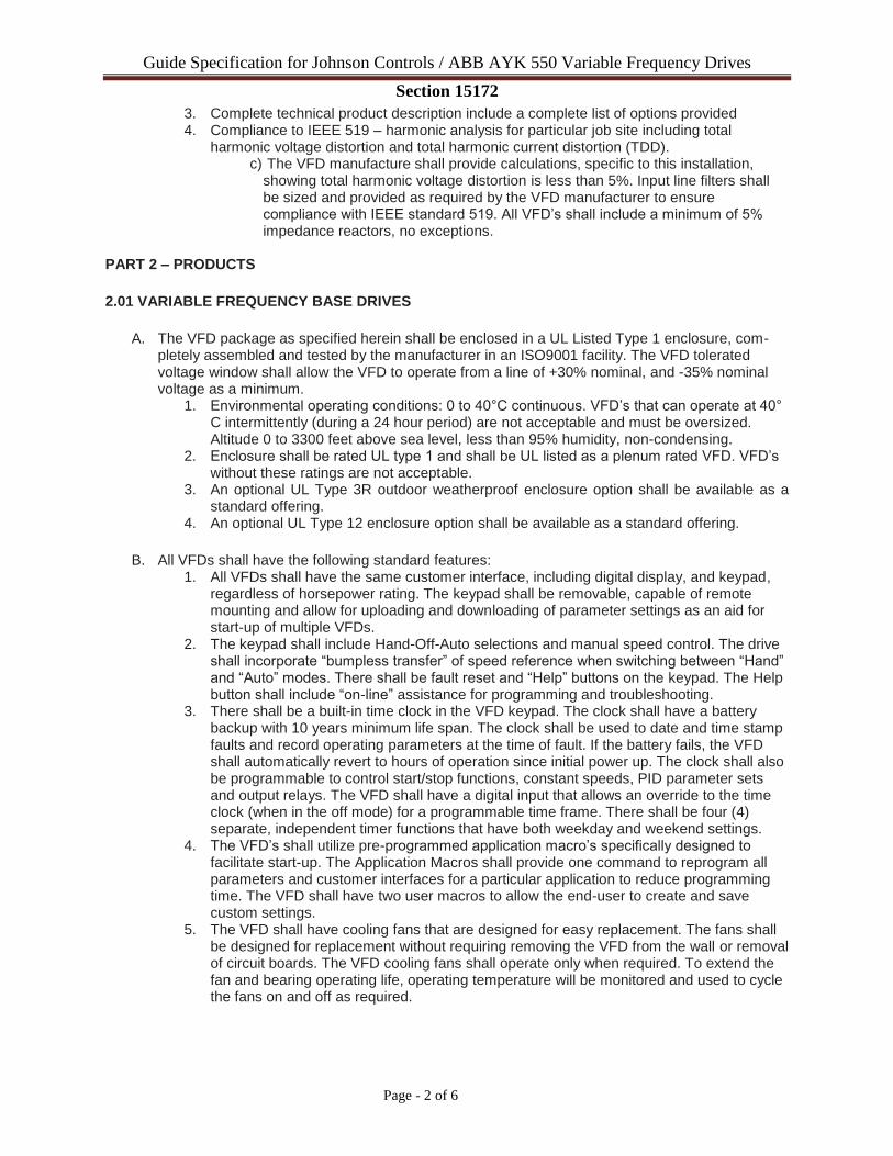
Guide Specification for Johnson Controls / ABB AYK 550 Variable Frequency Drives Section 15172
Page - 2 of 6
3. Complete technical product description include a complete list of options provided 4. Compliance to IEEE 519 – harmonic analysis for particular job site including total
harmonic voltage distortion and total harmonic current distortion (TDD). c) The VFD manufacture shall provide calculations, specific to this installation,
showing total harmonic voltage distortion is less than 5%. Input line filters shall be sized and provided as required by the VFD manufacturer to ensure compliance with IEEE standard 519. All VFD’s shall include a minimum of 5% impedance reactors, no exceptions.
PART 2 – PRODUCTS
2.01 VARIABLE FREQUENCY BASE DRIVES
A. The VFD package as specified herein shall be enclosed in a UL Listed Type 1 enclosure, com-
pletely assembled and tested by the manufacturer in an ISO9001 facility. The VFD tolerated voltage window shall allow the VFD to operate from a line of +30% nominal, and -35% nominal voltage as a minimum.
1. Environmental operating conditions: 0 to 40°C continuous. VFD’s that can operate at 40° C intermittently (during a 24 hour period) are not acceptable and must be oversized. Altitude 0 to 3300 feet above sea level, less than 95% humidity, non-condensing.
2. Enclosure shall be rated UL type 1 and shall be UL listed as a plenum rated VFD. VFD’s without these ratings are not acceptable.
3. An optional UL Type 3R outdoor weatherproof enclosure option shall be available as a standard offering.
4. An optional UL Type 12 enclosure option shall be available as a standard offering.
B. All VFDs shall have the following standard features:
1. All VFDs shall have the same customer interface, including digital display, and keypad, regardless of horsepower rating. The keypad shall be removable, capable of remote mounting and allow for uploading and downloading of parameter settings as an aid for start-up of multiple VFDs.
2. The keypad shall include Hand-Off-Auto selections and manual speed control. The drive shall incorporate “bumpless transfer” of speed reference when switching between “Hand” and “Auto” modes. There shall be fault reset and “Help” buttons on the keypad. The Help button shall include “on-line” assistance for programming and troubleshooting.
3. There shall be a built-in time clock in the VFD keypad. The clock shall have a battery backup with 10 years minimum life span. The clock shall be used to date and time stamp faults and record operating parameters at the time of fault. If the battery fails, the VFD shall automatically revert to hours of operation since initial power up. The clock shall also be programmable to control start/stop functions, constant speeds, PID parameter sets and output relays. The VFD shall have a digital input that allows an override to the time clock (when in the off mode) for a programmable time frame. There shall be four (4) separate, independent timer functions that have both weekday and weekend settings.
4. The VFD’s shall utilize pre-programmed application macro’s specifically designed to facilitate start-up. The Application Macros shall provide one command to reprogram all parameters and customer interfaces for a particular application to reduce programming time. The VFD shall have two user macros to allow the end-user to create and save custom settings.
5. The VFD shall have cooling fans that are designed for easy replacement. The fans shall be designed for replacement without requiring removing the VFD from the wall or removal of circuit boards. The VFD cooling fans shall operate only when required. To extend the fan and bearing operating life, operating temperature will be monitored and used to cycle the fans on and off as required.

Guide Specification for Johnson Controls / ABB AYK 550 Variable Frequency Drives Section 15172
Page - 3 of 6
6. The VFD shall be capable of starting into a coasting load (forward or reverse) up to full speed and accelerate or decelerate to setpoint without safety tripping or component damage (flying start).
7. The VFD shall have the ability to automatically restart after an over-current, over-voltage, under-voltage, or loss of input signal protective trip. The number of restart attempts, trial time, and time between attempts shall be programmable.
8. The overload rating of the drive shall be 110% of its normal duty current rating for 1 minute every 10 minutes, 130% overload for 2 seconds. The minimum FLA rating shall meet or exceed the values in the NEC/UL table 430-150 for 4-pole motors.
9. The VFD shall have an integral 5% impedance line reactor to reduce the harmonics to the power line and to add protection from AC line transients. The 5% impedance may be from dual (positive and negative DC bus) reactors, or 5% AC line reactors. VFD’s with only one DC reactor shall add AC line reactors.
10. The VFD shall include a coordinated AC transient protection system consisting of 4-120 joule rated MOV’s (phase to phase and phase to ground), a capacitor clamp, and 5% impedance reactors.
11. The VFD shall be capable of sensing a loss of load (broken belt / broken coupling) and signal the loss of load condition. The drive shall be programmable to signal this condition via a keypad warning, relay output and/or over the serial communications bus. Relay outputs shall include programmable time delays that will allow for drive acceleration from zero speed without signaling a false underload condition.
12. If the input reference (4-20mA or 2-10V) is lost, the VFD shall give the user the option of either (1) stopping and displaying a fault, (2) running at a programmable preset speed, (3) hold the VFD speed based on the last good reference received, or (4) cause a warning to be issued, as selected by the user. The drive shall be programmable to signal this condition via a keypad warning, relay output and/or over the serial communication bus.
13. The VFD shall have programmable “Sleep” and “Wake up” functions to allow the drive to be started and stopped from the level of a process feedback signal.
C. All VFDs to have the following adjustments: 1. Three (3) programmable critical frequency lockout ranges to prevent the VFD from
operating the load continuously at an unstable speed. 2. Two (2) PID Setpoint controllers shall be standard in the drive, allowing pressure or flow
signals to be connected to the VFD, using the microprocessor in the VFD for the closed loop control. The VFD shall have 250 ma of 24 VDC auxiliary power and be capable of loop powering a transmitter supplied by others. The PID setpoint shall be adjustable from the VFD keypad, analog inputs, or over the communications bus. There shall be two parameter sets for the first PID that allow the sets to be switched via a digital input, serial communications or from the keypad for night setback, summer/winter setpoints, etc. There shall be an independent, second PID loop that can utilize the second analog input and modulate one of the analog outputs to maintain setpoint of an independent process (i.e. valves, dampers, etc.). All setpoints, process variables, etc., to be accessible from the serial communication network. The setpoints shall be set in Engineering units and not require a percentage of the transducer input.
3. Two (2) programmable analog inputs shall accept current or voltage signals. 4. Two (2) programmable analog outputs (0-20ma or 4-20 ma). The outputs may be pro-
grammed to output proportional to Frequency, Motor Speed, Output Voltage, Output Current, Motor Torque, Motor Power (kW), DC Bus voltage, Active Reference, and other data.
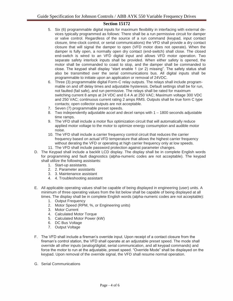
Guide Specification for Johnson Controls / ABB AYK 550 Variable Frequency Drives Section 15172
Page - 4 of 6
5. Six (6) programmable digital inputs for maximum flexibility in interfacing with external de-vices typically programmed as follows: There shall be a run permissive circuit for damper or valve control. Regardless of the source of a run command (keypad, input contact closure, time-clock control, or serial communications) the VFD shall provide a dry contact closure that will signal the damper to open (VFD motor does not operate). When the damper is fully open, a normally open dry contact (end-switch) shall close. The closed end-switch is wired to an VFD digital input and allows VFD motor operation. Two separate safety interlock inputs shall be provided. When either safety is opened, the motor shall be commanded to coast to stop, and the damper shall be commanded to close. The keypad shall display “start enable 1 (or 2) missing”. The safety status shall also be transmitted over the serial communications bus. All digital inputs shall be programmable to initiate upon an application or removal of 24VDC.
6. Three (3) programmable digital Form-C relay outputs. The relays shall include program-mable on and off delay times and adjustable hysteresis. Default settings shall be for run, not faulted (fail safe), and run permissive. The relays shall be rated for maximum switching current 8 amps at 24 VDC and 0.4 A at 250 VAC; Maximum voltage 300 VDC and 250 VAC; continuous current rating 2 amps RMS. Outputs shall be true form C type contacts; open collector outputs are not acceptable.
7. Seven (7) programmable preset speeds. 8. Two independently adjustable accel and decel ramps with 1 – 1800 seconds adjustable
time ramps. 9. The VFD shall include a motor flux optimization circuit that will automatically reduce
applied motor voltage to the motor to optimize energy consumption and audible motor noise.
10. The VFD shall include a carrier frequency control circuit that reduces the carrier frequency based on actual VFD temperature that allows the highest carrier frequency without derating the VFD or operating at high carrier frequency only at low speeds.
11. The VFD shall include password protection against parameter changes. D. The Keypad shall include a backlit LCD display. The display shall be in complete English words
for programming and fault diagnostics (alpha-numeric codes are not acceptable). The keypad shall utilize the following assistants:
1. Start-up assistants. 2. 2. Parameter assistants 3. 3. Maintenance assistant 4. 4. Troubleshooting assistant
E. All applicable operating values shall be capable of being displayed in engineering (user) units. A
minimum of three operating values from the list below shall be capable of being displayed at all times. The display shall be in complete English words (alpha-numeric codes are not acceptable):
1. Output Frequency 2. Motor Speed (RPM, %, or Engineering units) 3. Motor Current 4. Calculated Motor Torque 5. Calculated Motor Power (kW) 6. DC Bus Voltage 7. Output Voltage
F. The VFD shall include a fireman’s override input. Upon receipt of a contact closure from the
fireman’s control station, the VFD shall operate at an adjustable preset speed. The mode shall override all other inputs (analog/digital, serial communication, and all keypad commands) and force the motor to run at the adjustable, preset speed. “Override Mode” shall be displayed on the keypad. Upon removal of the override signal, the VFD shall resume normal operation.
G. Serial Communications
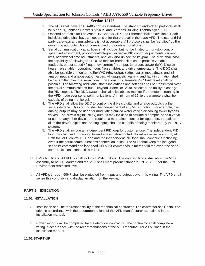
Guide Specification for Johnson Controls / ABB AYK 550 Variable Frequency Drives Section 15172
Page - 5 of 6
1. The VFD shall have an RS-485 port as standard. The standard embedded protocols shall be Modbus, Johnson Controls N2 bus, and Siemens Building Technologies FLN.
2. Optional protocols for LonWorks, BACnet MS/TP, and Ethernet shall be available. Each individual drive shall have an option slot for the protocol in the base VFD. The use of third party gateways and multiplexers is not acceptable. All protocols shall be “certified” by the governing authority. Use of non-certified protocols is not allowed.
3. Serial communication capabilities shall include, but not be limited to; run-stop control, speed set adjustment, proportional/integral/derivative PID control adjustments, current limit, accel/decel time adjustments, and lock and unlock the keypad. The drive shall have the capability of allowing the DDC to monitor feedback such as process variable feedback, output speed / frequency, current (in amps), % torque, power (kW), kilowatt hours (re-settable), operating hours (re-settable), and drive temperature. The DDC shall also be capable of monitoring the VFD relay output status, digital input status, and all analog input and analog output values. All diagnostic warning and fault information shall be transmitted over the serial communications bus. Remote VFD fault reset shall be possible. The following additional status indications and settings shall be transmitted over the serial communications bus – keypad “Hand” or “Auto” selected the ability to change the PID setpoint. The DDC system shall also be able to monitor if the motor is running in the VFD mode over serial communications. A minimum of 15 field parameters shall be capable of being monitored.
4. The VFD shall allow the DDC to control the drive’s digital and analog outputs via the serial interface. This control shall be independent of any VFD function. For example, the analog outputs may be used for modulating chilled water valves or cooling tower bypass valves. The drive’s digital (relay) outputs may be used to actuate a damper, open a valve or control any other device that requires a maintained contact for operation. In addition, all of the drive’s digital and analog inputs shall be capable of being monitored by the DDC system.
5. The VFD shall include an independent PID loop for customer use. The independent PID loop may be used for cooling tower bypass value control, chilled water value control, etc. Both the VFD control PID loop and the independent PID loop shall continue functioning even if the serial communications connection is lost. The VFD shall keep the last good set-point command and last good DO & PX commands in memory in the event the serial communications connection is lost.
H. EMI / RFI filters. All VFD’s shall include EMI/RFI filters. The onboard filters shall allow the VFD
assembly to be CE Marked and the VFD shall meet product standard EN 61800-3 for the First Environment restricted level.
I. All VFD’s through 50HP shall be protected from input and output power mis-wiring. The VFD shall
sense this condition and display an alarm on the keypad.
PART 3 – EXECUTION 11.01 INSTALLATION
A. Installation shall be the responsibility of the mechanical contractor. The contractor shall install the
drive in accordance with the recommendations of the VFD manufacturer as outlined in the installation manual.
B. Power wiring shall be completed by the electrical contractor. The contractor shall complete all
wiring in accordance with the recommendations of the VFD manufacturer as outlined in the installation manual.
11.02 START-UP
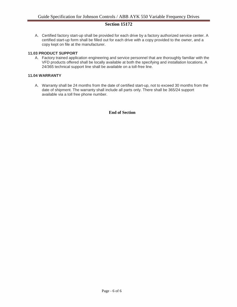
Guide Specification for Johnson Controls / ABB AYK 550 Variable Frequency Drives Section 15172
Page - 6 of 6
A. Certified factory start-up shall be provided for each drive by a factory authorized service center. A
certified start-up form shall be filled out for each drive with a copy provided to the owner, and a copy kept on file at the manufacturer.
11.03 PRODUCT SUPPORT A. Factory trained application engineering and service personnel that are thoroughly familiar with the
VFD products offered shall be locally available at both the specifying and installation locations. A 24/365 technical support line shall be available on a toll-free line.
11.04 WARRANTY
A. Warranty shall be 24 months from the date of certified start-up, not to exceed 30 months from the
date of shipment. The warranty shall include all parts only. There shall be 365/24 support available via a toll free phone number.
End of Section

SUBMITTAL PRIVILEGE AND CONFIDENTIALITY NOTICE: The information contained in this message is proprietary and confidential under applicable law, and is intended only for the use of the individual or entity named.
Date: 4.4.18
Purchaser: Strand Job Name: Crane Composites
Address:
Engineer: Strand
Phone: Glacier Project #: 16237
Fax:
WWW.THEGLACIERGROUP.NET
1001 Fourier Drive | Suite 202 | Madison WI 53717
P. 608-830-5210 | F.608-830-5215
The Glacier Group is please to provide the following equipment for Approval:
Equipment will not be released for production until (1) copy of the Approved submittal
is returned.
Air Cooled Chiller
Section 23 64 23
Edward Schnaubelt
The Glacier Group LLC
608.830.5211 Direct
608.830.5210 Main
608.830.5215 Fax
608.957.9980 Cell
www.theglaciergroup.net
1001 Fourier Drive, Suite 202
Madison WI 53717
Approved Approved As Noted Approved As Noted–Resubmit Not Approved
STRAND ASSOCIATES, INC.
THIS APPROVAL DOES NOT ALLEVIATE THE CONTRACTORS FROM REQUIREMENTS OF THE CONTRACT DOCUMENTS.
✔
By NES on Apr 06, 2018

WWW.THEGLACIERGROUP.NET
1001 Fourier Drive | Suite 202 | Madison WI 53717
P. 608-830-5210 | F.608-830-5215
YORK AIR COOLED CHILLER(S) (Build Time 9 weeks) TAG: CH-1
(1) York packaged R-134a air cooled chiller completely factory assembled and include the following:
300 Tons
Micro-Computer Control Center
Variable speed screw compressors
Hermetic Motor Compressors mounted on vibration isolators
Low sound fans
Compressor sound attenuation
Suction and Filter Dryer Service Valves
Non Fused disconnect switch
Unit vibration isolators
Louvered Condenser Guards
Flow switch provided by YORK (installed by others)
Factory start-up by York Service Technicians
5 year parts whole unit
BacNet Control Card
Connections for evap can be front or back relative to control panel
Freight FOB Jobsite ($500 has been added to this unit already for this)
ITEMS NOT INCLUDED
Factory Testing with Glycol is not available; will be tested with water
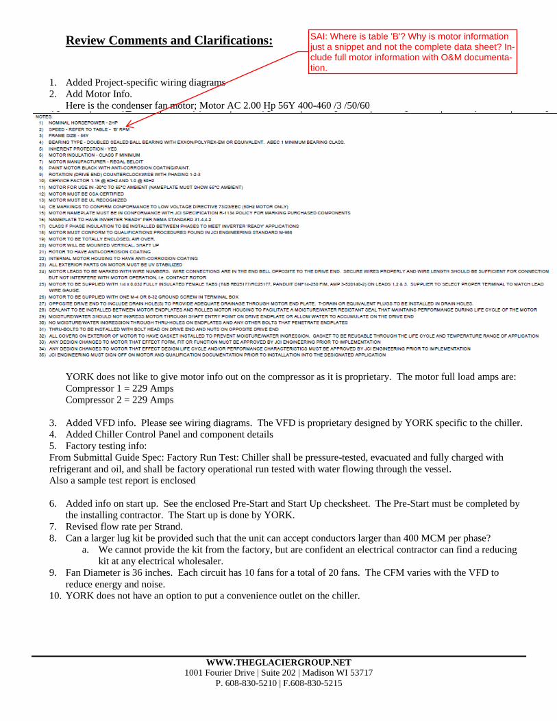
WWW.THEGLACIERGROUP.NET
1001 Fourier Drive | Suite 202 | Madison WI 53717
P. 608-830-5210 | F.608-830-5215
Review Comments and Clarifications:
1. Added Project-specific wiring diagrams
2. Add Motor Info.
Here is the condenser fan motor; Motor AC 2.00 Hp 56Y 400-460 /3 /50/60
YORK does not like to give motor info out on the compressor as it is proprietary. The motor full load amps are:
Compressor 1 = 229 Amps
Compressor 2 = 229 Amps
3. Added VFD info. Please see wiring diagrams. The VFD is proprietary designed by YORK specific to the chiller.
4. Added Chiller Control Panel and component details
5. Factory testing info:
From Submittal Guide Spec: Factory Run Test: Chiller shall be pressure-tested, evacuated and fully charged with
refrigerant and oil, and shall be factory operational run tested with water flowing through the vessel.
Also a sample test report is enclosed
6. Added info on start up. See the enclosed Pre-Start and Start Up checksheet. The Pre-Start must be completed by
the installing contractor. The Start up is done by YORK.
7. Revised flow rate per Strand.
8. Can a larger lug kit be provided such that the unit can accept conductors larger than 400 MCM per phase?
a. We cannot provide the kit from the factory, but are confident an electrical contractor can find a reducing
kit at any electrical wholesaler.
9. Fan Diameter is 36 inches. Each circuit has 10 fans for a total of 20 fans. The CFM varies with the VFD to
reduce energy and noise.
10. YORK does not have an option to put a convenience outlet on the chiller.
SAI: Where is table 'B'? Why is motor information just a snippet and not the complete data sheet? In-clude full motor information with O&M documenta-tion.

Air Cooled Screw Chiller Performance
Datasheet
MLP Effective Date:2/1/2018 NewProject
Generated on 2018-04-04 E.18.1.0.8518-D.60.0044(REV. v8_04.idd) Datasheet Spec
Unit Folder: CH-2-ALT Software Version: YW18.01b Page_1_of_2
Unit Tag Qty Model No Net Cooling
Capacity (ton.R)
Nominal Power
Volts-Ph-Hz Refrigerant Type
CH-2 1 YVAA0345EXV46BAVNXX 300.0 460-3-60.0 R134a
PIN:
YVAA0345EX V46BAVNXXX XAXLXXXX60 42XOFXXV19 4X1SXDA3BM XV5XXXXXXX XK1SXX
....5...10 ....5...20 ....5...30 ....5...40 ....5...50 ....5...60 ....5...70 ....5...80 ....5...90
Evaporator Data Evaporator Data (Cont.) Performance Data EWT (°F) 58.00 Fluid Volume (USGAL) 113.1 EER (Btu/W∙h) 9.879
LWT (°F) 42.00 Min. Flow Rate (USGPM) 269.5 NPLV.IP (Btu/W∙h) 18.53
Design Flow Rate (USGPM) 477.0 Max. Flow Rate (USGPM) 1062
Total Press. Drop (ft H2O) 19.5 Condenser Data Physical Data
Fluid Propylene
Glycol (%) 30 Ambient Temp. Design (°F) 100.0 Rigging Wt. (lb) 21072
Fouling Factor (h.ft².F/Btu) 0.000100 Altitude (ft) 0.000 Operating Wt. (lb) 21932
Number Passes 3 Compressor Type VSD Screw - Semi
Hermetic Refrigerant Charge (lb) 630.6
Electrical Data Circuit 1 2 3 4
Compressor kW 166.3 165.6
Compressor RLA 229 229
Fan QTY/FLA (each) 10 / 2.4 10 / 2.4
Single Point Min. Circuit Ampacity 569
Min. Fuse / CB Rating (A) 700
Max. Fuse / CB Rating (A) 700
Unit Short Circuit Withstand (STD) 50 kA [kA]
Wires Per Phase 3
Wire Range (Lug Size) #2 - 600 kcmil
Displacement Power Factor 0.95 Operating Condition Electrical Data Control kVA 3 Compressor kW 331.9
Total kW 364.4
Notes:
Certified in accordance with the AHRI Air-Cooled Water-Chilling Packages Using Vapor
Compression Cycle Certification Program, which is based on AHRI Standard 550/590 (I-P) and
AHRI Standard 551/591 (SI). Unit containing freeze protection fluids in the condenser or in the
evaporator with a leaving chilled fluid temperature above 32 DEG F [0 DEG C] is certified when
rated per the Standard with water. Certified units may be found in the AHRI Directory at
www.ahridirectory.org. Auxiliary components included in total KW - Oil heaters, Chiller controls.
Auxiliary power is already included in the compressor and fan power
Min DSD (Factory Purpose/Use only): 80 psig
Use Copper Conductors only
Displacement Power Factor refers to compressor only. Unit Power Factor depends on fan option
selected. Calculated value is available by request.
Minimum and maximum evaporator flow information are for full load ratings with water only. Contact Johnson Controls for application limits for gycol and
variable primary flow.
Evaporator Passes: 3, Condenser Type: M, Fan Type: V
Actuated suction service valves ARE NOT selected
Exclusion of actuated suction service valves will require incorporation of additional freeze protection including use of glycol, pump control or draining the
evaporator.
Part Load Rating Data
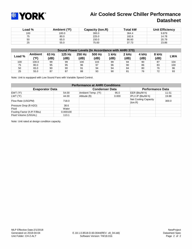
Air Cooled Screw Chiller Performance
Datasheet
MLP Effective Date:2/1/2018 NewProject
Generated on 2018-04-04 E.18.1.0.8518-D.60.0044(REV. v8_04.idd) Datasheet Spec
Unit Folder: CH-2-ALT Software Version: YW18.01b Page_2_of_2
Load % Ambient (°F) Capacity (ton.R) Total kW Unit Efficiency 100 100.0 300.0 364.4 9.879
75 80.0 225.0 182.6 14.78
50 65.0 150.0 86.60 20.79
25 55.0 75.00 37.73 23.86
Sound Power Levels (In Accordance with AHRI 370)
Load % Ambient
(°F)
63 Hz
(dB)
125 Hz
(dB)
250 Hz
(dB)
500 Hz
(dB)
1 kHz
(dB)
2 kHz
(dB)
4 kHz
(dB)
8 kHz
(dB) LWA
100 100.0 99 99 100 103 99 94 90 87 104
75 80.0 95 95 96 97 96 90 86 83 100
50 65.0 90 90 91 94 94 84 80 76 96
25 55.0 87 87 88 93 90 81 76 72 93
Note: Unit is equipped with Low Sound Fans with Variable Speed Control.
Performance at AHRI Conditions
Evaporator Data Condenser Data Performance Data EWT (°F) 54.00 Ambient Temp. (°F) 95.0 EER (Btu/W∙h) 11.51
LWT (°F) 44.00 Altitude (ft) 0.000 IPLV.IP (Btu/W∙h) 19.88
Flow Rate (USGPM) 718.0 Net Cooling Capacity
(ton.R) 300.0
Pressure Drop (ft H2O) 38.6
Fluid Water
Fouling Factor (h.ft².F/Btu) 0.000100
Fluid Volume (USGAL) 113.1
Note: Unit rated at design condition capacity.
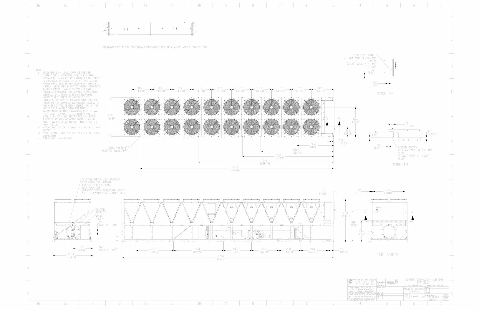

JOHNSON CONTROLS
FORM 201.28-EG1 (1016)
74
Power Wiring
���������������
�����������
���� ��������
���������� ������
�������������
���
�����������
����� �������� ���� �����
������
��� ����
���� ������� �����������
��������
��������
�������� ����� �������� ������� � ���� ���������� ����������
������ � ����
SINGLE POINT WIRING
LD18588
SAI: Provide equipment labels on O&M documen-tation.
SAI: Note 1 is missing from this wiring diagram.
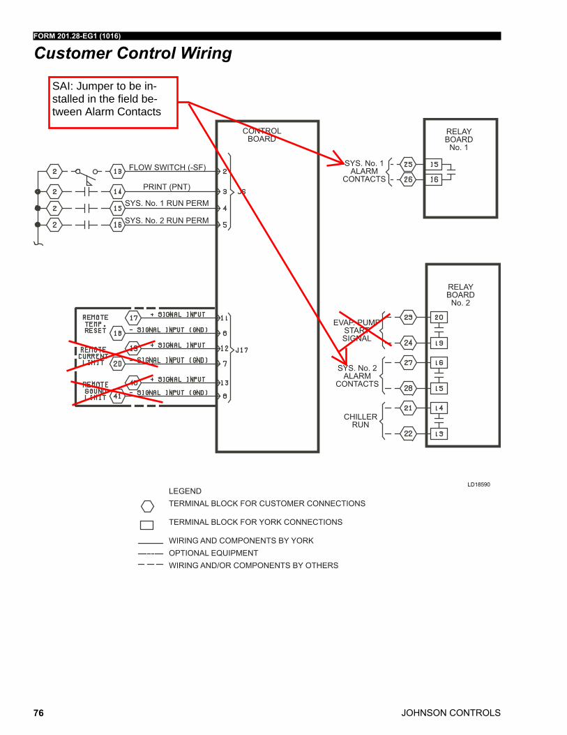
JOHNSON CONTROLS
FORM 201.28-EG1 (1016)
76
SYS. No. 1ALARM
CONTACTS
SYS. No. 2ALARM
CONTACTS
CHILLERRUN
EVAP. PUMPSTARTSIGNAL
SYS. No. 1 RUN PERM
SYS. No. 2 RUN PERM
FLOW SWITCH (-SF)
PRINT (PNT)
LEGENDTERMINAL BLOCK FOR CUSTOMER CONNECTIONS
TERMINAL BLOCK FOR YORK CONNECTIONS
WIRING AND COMPONENTS BY YORKOPTIONAL EQUIPMENTWIRING AND/OR COMPONENTS BY OTHERS
RELAYBOARD
No. 2
RELAYBOARD
No. 1
CONTROLBOARD
Customer Control Wiring
LD18590
SAI: Jumper to be in-stalled in the field be-tween Alarm Contacts
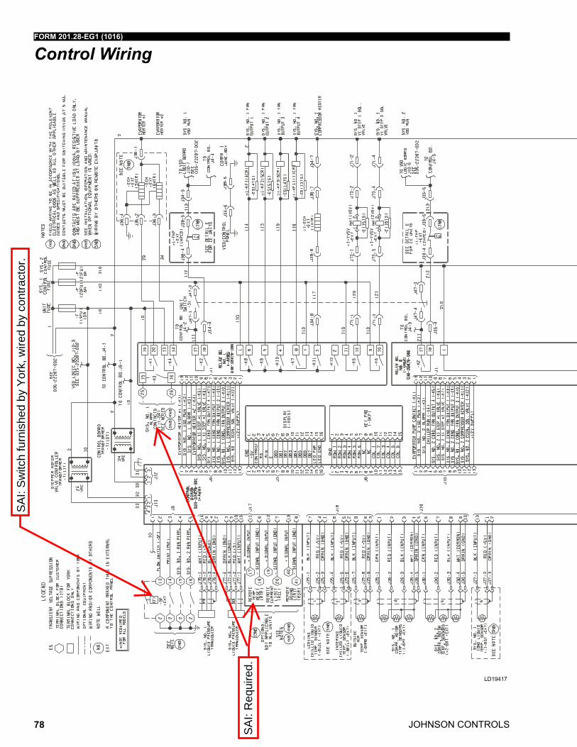
JOHNSON CONTROLS
FORM 201.28-EG1 (1016)
78
Control Wiring
LD19417
SAI:
Req
uire
d.
SAI:
Switc
h fu
rnis
hed
by Y
ork,
wire
d by
con
tract
or.

FORM 201.28-EG1 (1016)
JOHNSON CONTROLS 79
LD19417
Control Wiring (Cont'd)
LD19418
SAI:
Req
uire
d.

Factory Testing

MLP Effective Date:2/1/2018 NewProject
Generated on 2018-03-05 E.18.1.0.7841-D.60.0035(REV. v8_03.idd) Smart Specification
Unit Folder: CH-2 Software Version: YW18.01 Page_1_of_6
Air Cooled Screw Liquid Chiller -YORK YVAA R134a 50Hz & 60Hz
1. GENERAL
1.01. GENERAL REQUIREMENTS
The requirements of this Section shall conform to the general provisions of the Contract, including General and
Supplementary Conditions, Conditions of the Contract, and Contract Drawings.
1.02. SCOPE
Provide Microprocessor controlled, twin-screw compressor, air-cooled, liquid chillers of the scheduled capacities as shown
and indicated on the Drawings, including but not limited to:
1. Chiller package
2. Charge of refrigerant and oil
3. Electrical power and control connections
4. Chilled liquid connections
5. Manufacturer start-up
1.03. QUALITY ASSURANCE
A. Products shall be Designed, Tested, Rated and Certified in accordance with, and Installed in compliance with
applicable sections of the following Standards and Codes:
1. AHRI 550/590 – Water Chilling Packages Using the Vapor Compression Cycle
2. AHRI 370 – Sound Rating of Large Outdoor Refrigerating and Air-Conditioning Equipment
3. ANSI/ASHRAE 15 – Safety Code for Mechanical Refrigeration
4. ANSI/ASHRAE 34 – Number Designation and Safety Classification of Refrigerants
5. ASHRAE 90.1 – Energy Standard for Buildings Except Low-Rise Residential Buildings
6. ANSI/NFPA 70 – National Electrical Code (N.E.C.)
7. ASME Boiler and Pressure Vessel Code, Section VIII, Division 1
8. OSHA – Occupational Safety and Health Act
9. Manufactured in facility registered to ISO 9001
10. Conform to Intertek Testing Services for construction of chillers and provide ETL/cETL Listed Mark
B. Factory Run Test: Chiller shall be pressure-tested, evacuated and fully charged with refrigerant and oil, and shall
be factory operational run tested with water flowing through the vessel.
C. Chiller manufacturer shall have a factory trained and supported service organization.
D. Warranty: Manufacturer shall Warrant all equipment and material of its manufacture against defects in
workmanship and material for a period of eighteen (18) months from date of shipment or twelve (12) months from date
of start-up, whichever occurs first.
1.04. DELIVERY AND HANDLING
A. Unit shall be delivered to job site fully assembled with all interconnecting refrigerant piping and internal wiring ready
for field installation and charged with refrigerant and oil by the Manufacturer.
B. Provide protective covering over vulnerable components for unit protection during shipment. Fit nozzles and open
ends with plastic enclosures.
C. Unit shall be stored and handled per Manufacturer’s instructions.
MLP Effective Date:2/1/2018 NewProject
Generated on 2018-03-05 E.18.1.0.7841-D.60.0035(REV. v8_03.idd) Smart Specification
Unit Folder: CH-2 Software Version: YW18.01 Page_2_of_6
2. PRODUCTS
2.01. MANUFACTURERS
A. The design shown on the Drawings is based on YORK model YVAA chiller manufactured by Johnson Controls /
YORK. Alternate equipment will be acceptable if the manufacturer’s equipment meets the scheduled performance and
complies with these specifications. If equipment manufactured by a manufacturer other than that scheduled is utilized,
then the Mechanical Contractor shall be responsible for coordinating with the General Contractor and all affected
Subcontractors to insure proper provisions for installation of the furnished unit. This coordination shall include, but not
be limited to, the following:
1. Structural supports for units.
2. Piping size and connection/header locations.
3. Electrical power requirements and wire/conduit and overcurrent protection sizes.
4. Chiller physical size on plant layout.
5. Site noise considerations.
B. The Mechanical Contractor shall be responsible for all costs incurred by the General Contractor, Subcontractors,
and Consultants to modify the building provisions to accept the furnished alternate equipment.
2.02. GENERAL
A. Description: Furnish, Install, and Commission factory assembled, charged, and operational run tested air-cooled
screw compressor chiller as specified herein and shown on the Drawings. Chiller shall include, but is not limited to: a
complete system with multiple independent refrigerant circuits, semi hermetic twin screw compressors, shell and tube
hybrid falling film type evaporator, air-cooled condenser, R134a refrigerant, lubrication system, interconnecting wiring,
safety and operating controls including capacity controller, control center, motor starting components, and special
features as specified herein or required for safe, automatic operation.
B. Operating Characteristics:
1. Provide low and high ambient temperature control options as required to ensure unit is capable of starting and
operating from 0°F to 125°F (-18°C to 52°C) ambient temperature.
2. Cabinet: Unit panels, structural elements, control boxes and heavy gauge structural base shall be constructed
of painted galvanized steel. All exposed sheet steel shall be coated with baked on powder paint to meet 1000-
hour salt spray test in accordance with the ASTM B117 standard.
3. Shipping: Unit shall ship in one piece and shall require installer to provide only a single evaporator inlet and
outlet pipe connection. If providing chiller model that ships in multiple pieces, bid shall include all the material and
field labor costs for factory authorized personnel to install a trim kit to connect the pieces as well as all
interconnecting piping and wiring.
2.03. COMPRESSORS
A. Compressor Motors: Refrigerant suction-gas cooled accessible hermetic compressor motor, full suction gas flow
through 0.006” (0.1524 mm) maximum mesh screen, with inherent internal thermal overload protection and external
current overload on all three phases.
B. Balancing Requirements: All rotating parts shall be statically and dynamically balanced.
C. Lubrication System: External oil separators with no moving parts, 450 psig (31 barg) design working pressure, and
ETL listing shall be provided on the chiller. Refrigerant system differential pressure shall provide oil flow through
service replaceable, 0.5 micron, full flow, cartridge type oil filter internal to compressor. Filter bypass, less restrictive
media, or oil pump not acceptable.
D. Capacity Control: Compressors shall start at minimum load. Provide Microprocessor control to command
compressor capacity to balance compressor capacity with cooling load.

MLP Effective Date:2/1/2018 NewProject
Generated on 2018-03-05 E.18.1.0.7841-D.60.0035(REV. v8_03.idd) Smart Specification
Unit Folder: CH-2 Software Version: YW18.01 Page_3_of_6
2.04. REFRIGERANT CIRCUIT COMPONENTS
A. Refrigerant: R-134a. Classified as Safety Group A1 according to ASHRAE 34.
B. Equipment supplied shall comply with LEED Energy & Atmosphere Credit 4, Enhanced Refrigerant Management.
C. Each independent refrigerant circuit shall incorporate all components necessary for the designed operation
including: liquid line shut-off valve with charging port, low side pressure relief device, removable core filter-drier and
sight glass with moisture indicator.
D. Chiller manufacturer shall provide an independent circuit for each compressor to provide maximum redundancy
during chiller operation. If equipment does not have independent circuits per compressor, manufacturer shall provide
owner one spare compressor of each unique size.
E. Discharge lines shall be provided with manual compressor shut-off service valves.
2.05. HEAT EXCHANGERS
A. Evaporator:
1. Evaporator shall be shell and tube, hybrid falling film type with 3 pass arrangement to optimize efficiency and
refrigerant charge. Tubes shall be high-efficiency, internally and externally enhanced type copper tubes with
0.035” (0.89 mm) minimum wall thickness at all intermediate tube supports to provide maximum tube wall
thickness at the support area. Each tube shall be roller expanded into the tube sheets providing a leak proof seal,
and be individually replaceable. Independent refrigerant circuits shall be provided per compressor.
2. Constructed, tested, and stamped in accordance with applicable sections of ASME pressure vessel code for
minimum 235 psig (16 barg) refrigerant side design working pressure and 150 psig (10 barg) liquid side design
working pressure.
3. Water boxes shall be removable to permit tube cleaning and replacement. Water boxes shall include liquid
nozzle connections suitable for ANSI/AWWA C-606 couplings, welding, or flanges.
4. Provide vent and drain fittings, and thermo-statically controlled heaters to protect to 0°F (-17.8°C) ambient
temperature in off-cycle.
5. Connection location: Chilled liquid inlet and outlet nozzle connections are located at rear (opposite control
panel) end of unit.
B. Air-cooled Condenser:
1. Condenser coils shall be microchannel type, parallel flow aluminum alloy tubes metallurgically brazed as one
piece to enhanced aluminum alloy fins. Condenser coils shall be made of a single material to avoid galvanic
corrosion due to dissimilar metals. Tube and fin type condenser coils are an acceptable alternate when tubes and
fins are fabricated of the same metal material to avoid galvanic corrosion due to dissimilar metals. Coils shall be
designed for 350 psig (24 barg) or higher working pressure.
2. Unit shall include Louvered Panels (Condenser Coils): Painted steel to match unit panels, over external
condenser coil faces.
3. Low Sound Fans: Shall provide vertical air discharge from extended orifices. Fans shall be composed of
corrosion resistant aluminum hub and glass-fiber-reinforced polypropylene composite blades molded into a low-
noise airfoil section. Fan impeller shall be dynamically balanced for vibration-free operation. Fan guards of heavy
gauge, PVC (polyvinyl chloride) coated or galvanized steel.
4. Fan Motors: High efficiency, direct drive, 3-phase, insulation class “F”, current protected, Totally Enclosed Air-
Over (TEAO), with double sealed, permanently-lubricated ball bearings. Open Drip Proof (ODP) fan motors will
not be acceptable.
2.06. INSULATION
A. Material: Closed-cell, flexible, UV protected, thermal insulation complying with ASTM C 534 Type 2 (Sheet) for
preformed flexible elastomeric cellular thermal insulation in sheet and tubular form.

MLP Effective Date:2/1/2018 NewProject
Generated on 2018-03-05 E.18.1.0.7841-D.60.0035(REV. v8_03.idd) Smart Specification
Unit Folder: CH-2 Software Version: YW18.01 Page_4_of_6
B. Thickness: 3/4" (19mm).
C. Thermal conductivity: 0.26 (BTU/HR-Ft2-°F/in) maximum at 75°F mean temperature.
D. Factory-applied insulation over cold surfaces of liquid chiller components including evaporator shell, water boxes,
and suction line. Liquid nozzles shall be insulated by Contractor after pipe installation.
E. Adhesive: As recommended by insulation manufacturer and applied to 100 percent of insulation contact surface
including all seams and joints.
2.07. ACOUSTICAL DATA
A. Provide acoustical sound power or sound pressure level data in decibels (dB) at the scheduled eight (8) octave
band center frequencies. A-weighted sound data alone is not acceptable.
B. Provide all sound power or sound pressure level data at 100%, 75%, 50%, and 25% load.
C. Supplied equipment shall not exceed scheduled sound power or sound pressure level data at any load point. The
mechanical Contractor shall be responsible for any additional costs associated with equipment deviation.
D. Acoustical performance ratings shall be in accordance with AHRI Standard 370.
2.08. POWER AND ELECTRICAL REQUIREMENTS
A. Power/Control Panel:
1. Factory installed and wired NEMA 3R, powder painted steel cabinets with tool lockable, hinged, latched, and
gasket sealed outer doors equipped with wind struts for safer servicing. Provide main power connection(s),
compressor starters and fan motor contactors, current overloads, and factory wiring.
2. Panel shall include control display access door.
B. Single Point Power:
1. Provide single point power connection to chiller, shall be 3 phase of scheduled voltage.
2. Single Point Circuit Breaker: A unit-mounted Circuit Breaker with external lockable handle shall be provided at
the point of incoming single point connection for field connection, interconnecting wiring to the compressors, and
isolating the power voltage for servicing. Incoming power wiring must comply with local codes. Circuit breaker
shall be sized to provide the motor branch circuit protection, short circuit protection and ground fault protection for
the motor branch-circuit conductors, the motor control apparatus and the motors.
C. Control Transformer: Power panel shall be supplied with a factory mounted and wired control transformer that will
supply all unit control voltage from the main unit power supply. Transformer shall utilize scheduled line voltage on the
primary side and provide 115V/1Ø on secondary.
D. Short Circuit Withstand Rating of the chiller electrical enclosure shall be (380, 400, & 460V: 65,000 Amps). Rating
shall be published in accordance with UL508.
E. Motor Starters: Motor starters shall be Variable Frequency Drive type with zero electrical inrush current. Wye-Delta,
Solid State, and Across the Line type starters will not be acceptable.
a. Compressor Variable Frequency Drive(s) shall meet 6kV surge rating as recommended by IEEE C62.41.1
and C62.41.2.
F. Power Factor:
1. Provide equipment with power factor correction capacitors as required to maintain a displacement power factor
of 95% at all load conditions.
2. The installing contractor is responsible for additional cost to furnish and install power factor correction
capacitors if they are not factory mounted and wired.
G. All exposed power wiring shall be routed through liquid-tight, UV-stabilized, non-metallic conduit.
H. Supplied equipment shall not exceed scheduled Minimum Circuit Ampacity (MCA.) The mechanical Contractor
shall be responsible for any additional costs associated with equipment deviation.
MLP Effective Date:2/1/2018 NewProject
Generated on 2018-03-05 E.18.1.0.7841-D.60.0035(REV. v8_03.idd) Smart Specification
Unit Folder: CH-2 Software Version: YW18.01 Page_5_of_6
2.09. CONTROLS
A. General:
1. Provide automatic control of chiller and waterside economizer operation including compressor start/stop and
load/unload, anti-recycle timers, condenser fans, evaporator pump, evaporator heater, waterside economizer
bypass value, unit alarm contacts and run signal contacts.
2. Chiller shall automatically reset to normal chiller operation after power failure.
3. Unit operating software shall be stored in non-volatile memory. Field programmed set points shall be retained
in lithium battery backed regulated time clock (RTC) memory for minimum 5 years.
4. Alarm contacts shall be provided to remote alert for any unit or system safety fault.
B. Display and Keypad:
1. Provide minimum 80 character liquid crystal display that is both viewable in direct sunlight and has LED
backlighting for nighttime viewing. Provide one keypad and display panel per chiller.
2. Display and keypad shall be accessible through display access door without opening main control/electrical
cabinet doors.
3. Display shall provide a minimum of unit setpoints, status, electrical data, temperature data, pressures, safety
lockouts and diagnostics without the use of a coded display.
4. Descriptions in English (or available language options), numeric data in English (or Metric) units.
5. Sealed keypad shall include unit On/Off switch.
C. Programmable Setpoints (within Manufacturer limits): Display language, chilled liquid cooling mode, local/remote
control mode, display units mode, system lead/lag control mode, remote temperature reset, remote current limit,
remote sound limit, low ambient temperature cutout enable/disable, leaving chilled liquid setpoint and range,
maximum remote temperature reset.
D. Display Data: Chilled liquid leaving and entering temperatures; outside ambient air temperature; lead system;
evaporator pump status; active remote control; compressor suction, discharge, and oil pressures per refrigerant
circuit; compressor discharge, motor, and oil temperatures per refrigerant circuit; saturation temperatures per
refrigerant circuit; compressor speed; condenser fan status; condenser subcooling temperature; condenser drain
valve percentage open; compressor capacity in percentage of Full Load Amps; compressor number of starts; run
time; operating hours; evaporator heater status; history data for last ten shutdown faults; history data for last 20
normal (non-fault) shutdowns.
E. Predictive Control Points: Unit controls shall avoid safety shutdown when operating outside design conditions by
optimizing the chiller controls and cooling load output to stay online and avoid safety limits being reached. The system
shall monitor the following parameters and maintain the maximum cooling output possible without shutdown of the
equipment: motor current, suction pressure, discharge pressure, starter internal ambient temperature, and starter
baseplate temperature.
F. System Safeties: Shall cause individual compressor systems to perform auto-reset shut down if: high discharge
pressure or temperature, low suction pressure, low motor current, high/low differential oil pressure, low discharge
superheat, high motor temperature, system control voltage.
G. Unit Safeties: Shall be automatic reset and cause compressors to shut down if: high or low ambient temperature,
low leaving chilled liquid temperature, under voltage, flow switch operation. Contractor shall provide flow switch and
wiring per chiller manufacturer requirements.
H. Manufacturer shall provide any controls not listed above, necessary for automatic chiller operation. Mechanical
Contractor shall provide field control wiring necessary to interface sensors to the chiller control system.
2.10. ACCESSORIES AND OPTIONS
Some accessories and options supersede standard product features. All options are factory-mounted unless otherwise
noted.
A. CONTROLS OPTIONS:
MLP Effective Date:2/1/2018 NewProject
Generated on 2018-03-05 E.18.1.0.7841-D.60.0035(REV. v8_03.idd) Smart Specification
Unit Folder: CH-2 Software Version: YW18.01 Page_6_of_6
1. Building Automation System Interface: Chiller to accept BACnet MS/TP, N2 and Modbus protocol from BAS (by
others). BACnet to be BACnet Testing Laboratories (BTL) listed and support BACnet Automatic Discovery to
eliminate field commissioning of chiller controls.
B. GENERAL OPTIONS:
1. Differential Pressure Switch: 3-45 psig (0.2-3 barg) range with 1/4” NPTE pressure connections. (Field
Mounted by Contractor).
3. EXECUTION
3.01. INSTALLATION
A. General: Rig and Install in full accordance with Manufacturer’s requirements, Project drawings, and Contract
documents.
B. Location: Locate chiller as indicated on drawings, including cleaning and service maintenance clearance per
Manufacturer instructions. Adjust and level chiller on support structure.
C. Components: Installing Contractor shall provide and install all auxiliary devices and accessories for fully operational
chiller.
D. Electrical: Coordinate electrical requirements and connections for all power feeds with Electrical Contractor.
E. Controls: Coordinate all control requirements and connections with Controls Contractor.
F. Finish: Installing Contractor shall paint damaged and abraded factory finish with touch-up paint matching factory
finish.


![BID ADDENDUM - Scpurchasing.sc.edu/solicitations/H27-Z155 Addendum One.pdf · mech room 106 --> abated mechanical rm first floor & hvac rooms --> hot water pipe [160 lin. ft.] mechanical](https://img.pdfslide.us/doc/110x75/5f07a6607e708231d41e0b62/bid-addendum-addendum-onepdf-mech-room-106-abated-mechanical-rm-first.jpg)