Embed Size (px)
Citation preview

Crane installation manualon light vehicles
Mod. MD.0.218_GB Ed. 1 06/13

Via Mediterraneo, 642022 - Boretto - Reggio Emilia - Italy
Tel. +39 - 0522-96 30 08 - Fax +39 - 0522-96 30 39- 64 -
- Crane Fitting Directive - Manual for crane mounting on commercial vehicles -
Via Mediterraneo, 642022 - Boretto - Reggio Emilia - Italy
Tel. +39 - 0522-96 30 08 - Fax +39 - 0522-96 30 39- 1 -
1 – INTRODUCTION
1.1 BASIC INFORMATION
This manual holds the information and prescriptions to be respected in order to install correctly theMAXILIFT cranes on vehicles, as well as to check the correct mounting when the work is finished.For further evidence and better readability, in such manual are used the following symbologies:
DANGER: this symbol is used with reference to activities which caninvolve risk or danger for people.
ATTENTION: this symbol is used with reference to activities which caninvolve risk or danger for things.
IMPORTANT: it indicates useful suggestions or hints for crane installation
NOTE: it indicates information which can facilitate crane mountingand installation.
ATTENTION
Read carefully this manual before starting each operation related to crane installation.
ATTENTION
Read carefully the “INSTALLATION INSTRUCTIONS” manual of the vehicle’s manufacturer be-fore starting crane installation.
!
- Crane Fitting Directive - Manual for crane mounting on commercial vehicles -
Via Mediterraneo, 642022 - Boretto - Reggio Emilia - Italy
Tel. +39 - 0522-96 30 08 - Fax +39 - 0522-96 30 39- 2 -
The Maxilift cranes can be installed only by workshops expressly authorised by Next Hydraulics S.r.l.for this purpose.Such workshops must be equipped with the devices, machinery, tools and implements proper and inorder with the Accident Prevention Norms in force.Mounting must be carried out by trained and qualified staff, with a good knowledge of the technical state-of-the-art, which must cling to the prescriptions of this manual and the Installation Instructions of thevehicle’s Manufacturer while executing the work.Such staff must have a specific competence in the safety devices installed on Maxilift cranes, evenavailing itself of the free Training Courses held, periodically or on request, at Next Hydraulics S.r.l..
ATTENTION
In case of doubts or uncertainty always consult Next Hydraulics s.r.l..
The installation of the crane or other options must in no way change or affect negatively the functionalityof the different vehicle’s parts. As a simple and not exhaustive example, we remind that:
1 - the installation must not change the breathing and ventilation conditions foreseen by the vehicle’smanufacturer for the different parts or services (motor, batteries, brakes, heat exchangers, etc.)
2 - the installation must not compromise the accessibility to the several parts and systems of the vehicle,nor compromise their easy maintenance, inspections, repair interventions
3 - the installation must not compromise duration and endurance to the corrosion of the different vehicle’sparts; in case of modifications or workings, provide for the restoration by the proper treatments
4 - special attention must be used when working with welding machines or other tools near to the hosesof brakes, air and electricity system. Such parts must be always adequately protected and, if necessary,temporarily removed
5 - the interventions on vehicle’s electric system (for instance: additions, shunts, etc.) must be carriedout with cables and water-tight joints of the same type of those original. The cables are to be protectedby sheaths and steadily fixed on safe points. Do not change the original ground connections of vehicle’ssystem
6 - for further information consult the Installation Instructions manual of vehicle’s manufacturer.
ATTENTION
During the installation, always keep within reach this manual and the “INSTALLATION INSTRUC-TIONS” manual of the vehicle’s manufacturer. Should you notice on both manuals some clash-ing data or instructions on a same matter, always apply the most conservative ones in terms ofsafety.
In accordance with the policy of steady improvement of its products, Next Hydraulics S.r.l. reserves theright to bring to them modifications at any time. Therefore, in some points this manual could not exactlysuit what noticed on the crane during mounting.Always make sure to have received (and to be using) the last release of the manual!In case of doubt, always apply to Next Hydraulics s.r.l..
- Crane Fitting Directive - Manual for crane mounting on commercial vehicles -
Via Mediterraneo, 642022 - Boretto - Reggio Emilia - Italy
Tel. +39 - 0522-96 30 08 - Fax +39 - 0522-96 30 39- 3 -
1.2 “MACHINE DIRECTIVE”
All the machines sold inside the European Union’s territory must fulfil the regulations of the 2006/42/CE(“MACHINE DIRECTIVE”) in the version in force.Therefore, each Maxilift crane is fitted with the safety devices required, it bears a plate carrying the CEmark in a visible position, and is delivered accompanied by relevant Conformity Declaration.The installer carrying out mounting, by incorporating the Maxilift crane in the vehicle produces a newmachine: a truck loader, ready to be put into service. Therefore, he becomes the manufacturer of thisnew machine and must comply with the Directive’s provisions concerning design, building, safety infunctioning and use.He must keep all of this recorded in the Technical Dossier he is compelled to draw up.After having made sure, by proper tests and practical exams, of the correspondence to the requirements,the installer places his own CE plate and releases his own Conformity Certificate.
NOTE
We remind that the non-fulfilment to the above involves, in case of accidents:- criminal sanctions- fines (compensation for economic damage caused by defective product)- withdrawal from the market of the machine itself, and eventually also others of the same
series.
1.3 REFERENCE NORMS
Directives 2006/42/CE , 2004/108/EGNorm EN 12999 in the version in forceNorm CUNA NC 034-05 (Release. 1984), Norm DIN 15019INSTALLATION AND MOUNTING INSTRUCTIONS, Manufacturers of various industrial vehiclesUse manuals of hydraulic hoses, from various ManufacturersUse manuals of hydraulic steel pipes and fittings, from various Manufacturers.Use manuals of pumps and PTO’s, from various Manufacturers
- Crane Fitting Directive - Manual for crane mounting on commercial vehicles -
Via Mediterraneo, 642022 - Boretto - Reggio Emilia - Italy
Tel. +39 - 0522-96 30 08 - Fax +39 - 0522-96 30 39- 4 -
2 – MOUNTING PREPARATION
2.1 STARTING PREPARATION
Each Maxilift crane is delivered protected and wrapped up in a transparent nylon bag, placed on shorttimbers of proper size and sturdiness, even in order to allow moving by transpallet or forklift.Along with each crane the following are delivered:
Materials Documents
- For cranes with outrigger base: - Warranty certificatebrackets, tie bolts fitted with nuts and lock - Use and maintenance manualnuts, relevant support plates for fixing tothe vehicle’s frame
- For cranes in standard version: - Spare parts manualtie bolts, nuts and lock nuts
- Grease cartridge gr. 400, type recommended - CE conformity declarationfor slewing gears lubrication - Fac-simile of Installer’s CE Conformity
Declaration
- A second loading capacity plate (the first is - Certificate of origin (only Italy)applied on the crane boom), to be placed in the - other certificates when compulsory in themost proper position by the crane control place destination Country, or expressly requested
by the Customer.
- Hydraulic power pack (only for electric cranes)
- Two keys for the main board switch.
ATTENTION
Check that the above equipment is delivered complete. If not, get in touch with Next Hydraulicsfor the restoration of the missing items.
2.2 CRANE MOVING AND STORAGE
Each Maxilift crane is equipped with a lifting connection placed on the upper side of main boom. Forlifting the crane, cut the upper part of the nylon package, in order to release such connection. This isadequately marked by stickers and allows a safe crane lifting in case it is handled by a steel shackle ofproper dimensions and capacity.
- Crane Fitting Directive - Manual for crane mounting on commercial vehicles -
Via Mediterraneo, 642022 - Boretto - Reggio Emilia - Italy
Tel. +39 - 0522-96 30 08 - Fax +39 - 0522-96 30 39- 5 -
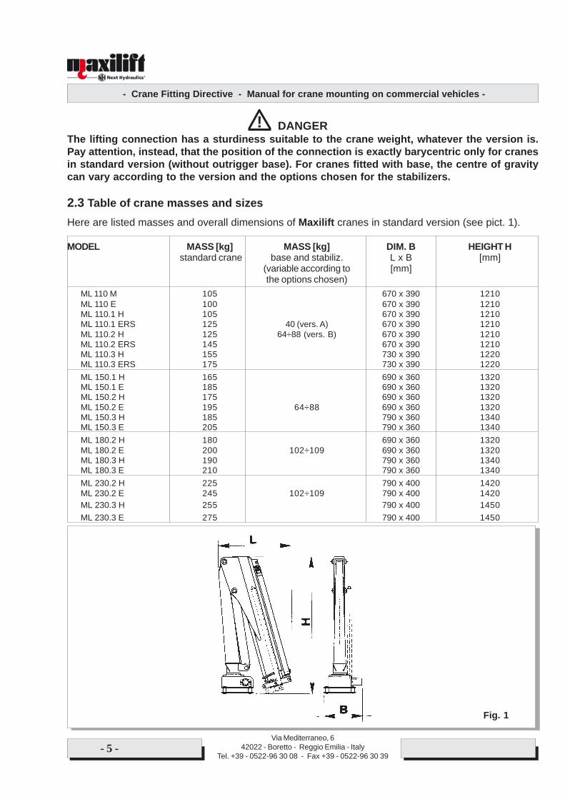
DANGERThe lifting connection has a sturdiness suitable to the crane weight, whatever the version is.Pay attention, instead, that the position of the connection is exactly barycentric only for cranesin standard version (without outrigger base). For cranes fitted with base, the centre of gravitycan vary according to the version and the options chosen for the stabilizers.
2.3 Table of crane masses and sizesHere are listed masses and overall dimensions of Maxilift cranes in standard version (see pict. 1).
MODEL MASS [kg] MASS [kg] DIM. B HEIGHT H standard crane base and stabiliz. L x B [mm]
(variable according to [mm]the options chosen)
ML 110 M 105 670 x 390 1210ML 110 E 100 670 x 390 1210ML 110.1 H 105 670 x 390 1210ML 110.1 ERS 125 40 (vers. A) 670 x 390 1210ML 110.2 H 125 64÷88 (vers. B) 670 x 390 1210ML 110.2 ERS 145 670 x 390 1210ML 110.3 H 155 730 x 390 1220ML 110.3 ERS 175 730 x 390 1220ML 150.1 H 165 690 x 360 1320ML 150.1 E 185 690 x 360 1320ML 150.2 H 175 690 x 360 1320ML 150.2 E 195 64÷88 690 x 360 1320ML 150.3 H 185 790 x 360 1340ML 150.3 E 205 790 x 360 1340ML 180.2 H 180 690 x 360 1320ML 180.2 E 200 102÷109 690 x 360 1320ML 180.3 H 190 790 x 360 1340ML 180.3 E 210 790 x 360 1340ML 230.2 H 225 790 x 400 1420ML 230.2 E 245 102÷109 790 x 400 1420ML 230.3 H 255 790 x 400 1450ML 230.3 E 275 790 x 400 1450
!
Fig. 1
- Crane Fitting Directive - Manual for crane mounting on commercial vehicles -
Via Mediterraneo, 642022 - Boretto - Reggio Emilia - Italy
Tel. +39 - 0522-96 30 08 - Fax +39 - 0522-96 30 39- 6 -
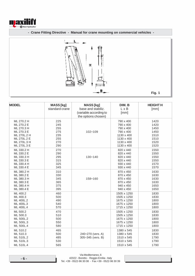
MODEL MASS [kg] MASS [kg] DIM. B HEIGHT H standard crane base and stabiliz. L x B [mm]
(variable according to [mm]the options chosen)
ML 270.2 H 225 790 x 400 1420ML 270.2 E 245 790 x 400 1420ML 270.3 H 255 790 x 400 1450ML 270.3 E 275 102÷109 790 x 400 1450ML 270L.2 H 235 1130 x 400 1510ML 270L.2 E 255 1130 x 400 1510ML 270L.3 H 270 1130 x 400 1520ML 270L.3 E 290 1130 x 400 1520ML 330.2 H 270 820 x 440 1550ML 330.2 E 290 820 x 440 1550ML 330.3 H 295 130÷140 820 x 440 1550ML 330.3 E 315 820 x 440 1550ML 330.4 H 325 930 x 440 1570ML 330.4 E 345 930 x 440 1570ML 380.2 H 310 870 x 450 1630ML 380.2 E 330 870 x 450 1630ML 380.3 H 345 158÷160 870 x 450 1630ML 380.3 E 365 870 x 450 1630ML 380.4 H 375 940 x 450 1650ML 380.4 E 395 940 x 450 1650ML 400.2 460 1505 x 1250 1830ML 400.3 500 1505 x 1250 1830ML 400L.2 490 1675 x 1250 1800ML 400L.3 540 1675 x 1250 1800ML 400L.4 570 1715 x 1250 1800ML 500.2 470 1505 x 1250 1830ML 500.3 510 1505 x 1250 1830ML 500L.2 500 1675 x 1250 1800ML 500L.3 550 1675 x 1250 1800ML 500L.4 580 1715 x 1250 1800ML 510.2 465 1380 x 545 1830ML 510.3 500 240÷270 (vers. A) 1380 x 545 1830ML 510L.2 485 305÷345 (vers. B) 1510 x 545 1790ML 510L.3 530 1510 x 545 1790ML 510L.4 565 1510 x 545 1790
Fig. 1

- Crane Fitting Directive - Manual for crane mounting on commercial vehicles -
Via Mediterraneo, 642022 - Boretto - Reggio Emilia - Italy
Tel. +39 - 0522-96 30 08 - Fax +39 - 0522-96 30 39- 7 -
ATTENTION
When a forklift is not available, only the above mentioned connection must be used for cranelifting.
ATTENTION
Before moving the crane, make sure to have a lifting device with proper capacity. Relevantoptions (shackles, chains, hooks, ropes, etc.) must have a suitable capacity and be in goodworking order.
ATTENTION
The crane moving area must be cleared, delimited by proper signals or by a staff specially chargedfor such purpose. Nobody is to be in such area, so that accidental falls of the crane itself, or itsparts, or its options, due to mistakes in movement, impacts or floors unevenness can occurwithout consequences for people.
The crane is to be cautiously moved, in order to avoid damages to its parts, especially to the componentsof the electric and hydraulic circuits, and the safety and protection systems. Should it be noticed that,during transport or moving, some damages have occurred, the parts concerned are to be replaced byoriginal Next Hydraulics spare parts before putting the crane into operation.
ATTENTION
Check carefully the external state and aspect of valves and safety components. In case of somedoubts on their efficiency and functioning, remove and return them to Next Hydraulics s.r.l. forthe necessary inspections.Check carefully the external state and aspect of valves and safety components. In case of some doubtson their efficiency and functioning, remove and return them to Next Hydraulics s.r.l. for the necessaryinspections.
ATTENTION
Should the crane need to be stored for some times placed on timbers, take care of securing it ina safe way by ropes or other means suitable to ensure its protection and prevent its overturning.
The crane is to be stored in a covered and dry place. The nylon bag must be removed only when mountingthe crane on the vehicle.
IMPORTANT
After long storage periods (for instance: 12 months or more, even depending on the environ-mental conditions), when putting the crane into service for the first time you could notice someanomalies due to the seals sticking on rods, sliders, valves, etc. because of long inactivity.In case of some doubts, consult Next Hydraulics.
- Crane Fitting Directive - Manual for crane mounting on commercial vehicles -
Via Mediterraneo, 642022 - Boretto - Reggio Emilia - Italy
Tel. +39 - 0522-96 30 08 - Fax +39 - 0522-96 30 39- 8 -
2.4 PRECAUTIONS TO BE RESPECTED
As a simple and not exhaustive example, we hereby report some basic precautions regarding theinstallation operations:1 - locate and delimit the area appointed for mounting, keeping it clear from the transit of other machines,
equipments, personnel2 - it is forbidden to carry out any welding operation, or involving flames, in narrow or not adequately
vented places, or close to inflammables3 - be careful when entering narrow spaces (or slipping in some parts of the body)4 - pay attention to dangers and risks coming from parts in motion, corrosives or toxicants (for instance:
batteries acids), fluids under pressure5 - apparel must be composed by clothes conform to the accident preventing norms6 - all the machines or some of their parts, or other equipments lifted from the ground, or which might
cause crushing or shearing, must be safely locked in their position7 - operate in healthy environments, well aired, with clean and dry floors. Avoid using inflammable or
toxic detergents.

- Crane Fitting Directive - Manual for crane mounting on commercial vehicles -
Via Mediterraneo, 642022 - Boretto - Reggio Emilia - Italy
Tel. +39 - 0522-96 30 08 - Fax +39 - 0522-96 30 39- 9 -
3 – CRANE - VEHICLE MESHING
3.1 Minimum vehicle
A well-chosen crane-vehicle coupling emphasizes the installer’s professional qualities, and assuresCustomer’s satisfaction, as it contributes to ensure the safety of working operations, the reduction oftruck wear and tear and, consequently, the economy of use during the years.As a simple indicative example, to be used only for a first very indicative evaluation, we hereby report inthe following tables the vehicle’s “minimum wheelbase” and “minimum pitch” rates required for the Maxiliftcrane models.Such couplings are always, and in any case, to be first verified with calculation, and then with practicaltest according to the procedures indicated in following paragraphs.
MOUNTING WITHOUT SUPPLEMENTARY OUTRIGGERS Table [A]
Crane model Vehicle’s minimum tare [Kg.] Vehicle’s minimum(vehicle’s tare when completely fitted, wheelbase (mm)
except the crane itself and itsstabilizing system)
ML 110 1400 2000ML 150 1400 2450ML 180 1840 2800ML 230 2000 2800ML 270-ML 330 2200 2800ML 380 1850 3200ML 510 3200 3690
MOUNTING WITH SUPPLEMENTARY OUTRIGGERS Table [B]
Crane model Vehicle’s minimum tare [Kg.] Vehicle’s minimum(vehicle’s tare when completely fitted, wheelbase (mm)
except the crane itself and itsstabilizing system)
ML 110 1200 1800ML 150 1200 2200ML 180 1450 2200ML 230 1450 2450ML 270-ML 330 1750 2450ML 380 1750 2800ML 510 2800 3100
- Crane Fitting Directive - Manual for crane mounting on commercial vehicles -
Via Mediterraneo, 642022 - Boretto - Reggio Emilia - Italy
Tel. +39 - 0522-96 30 08 - Fax +39 - 0522-96 30 39- 10 -
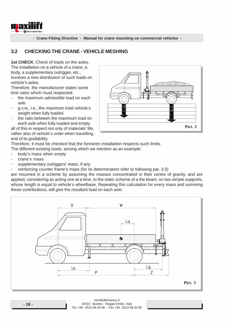
3.2 CHECKING THE CRANE - VEHICLE MESHING
1st CHECK: Check of loads on the axles.The installation on a vehicle of a crane, abody, a supplementary outrigger, etc.,involves a new distribution of such loads onvehicle’s axles.Therefore, the manufacturer states somelimit rates which must respected:- the maximum admissible load on each
axle- g.v.w., i.e., the maximum total vehicle’s
weight when fully loaded- the ratio between the maximum load on
each axle when fully loaded and emptyall of this in respect not only of materials’ life,rather also of vehicle’s order when travelling,and of its guidability.Therefore, it must be checked that the foreseen installation respects such limits.The different existing loads, among which we mention as an example:- body’s mass when empty- crane’s mass- supplementary outriggers’ mass, if any- reinforcing counter frame’s mass (for its determination refer to following par. 3.5)are resumed in a scheme by assuming the masses concentrated in their centre of gravity, and areapplied, considering as acting one at a time, to the static scheme of a the beam, on two simple supports,whose length is equal to vehicle’s wheelbase. Repeating this calculation for every mass and summingthese contributions, will give the resultant load on each axle.
Pict. 2
Pict. 3
- Crane Fitting Directive - Manual for crane mounting on commercial vehicles -
Via Mediterraneo, 642022 - Boretto - Reggio Emilia - Italy
Tel. +39 - 0522-96 30 08 - Fax +39 - 0522-96 30 39- 11 -
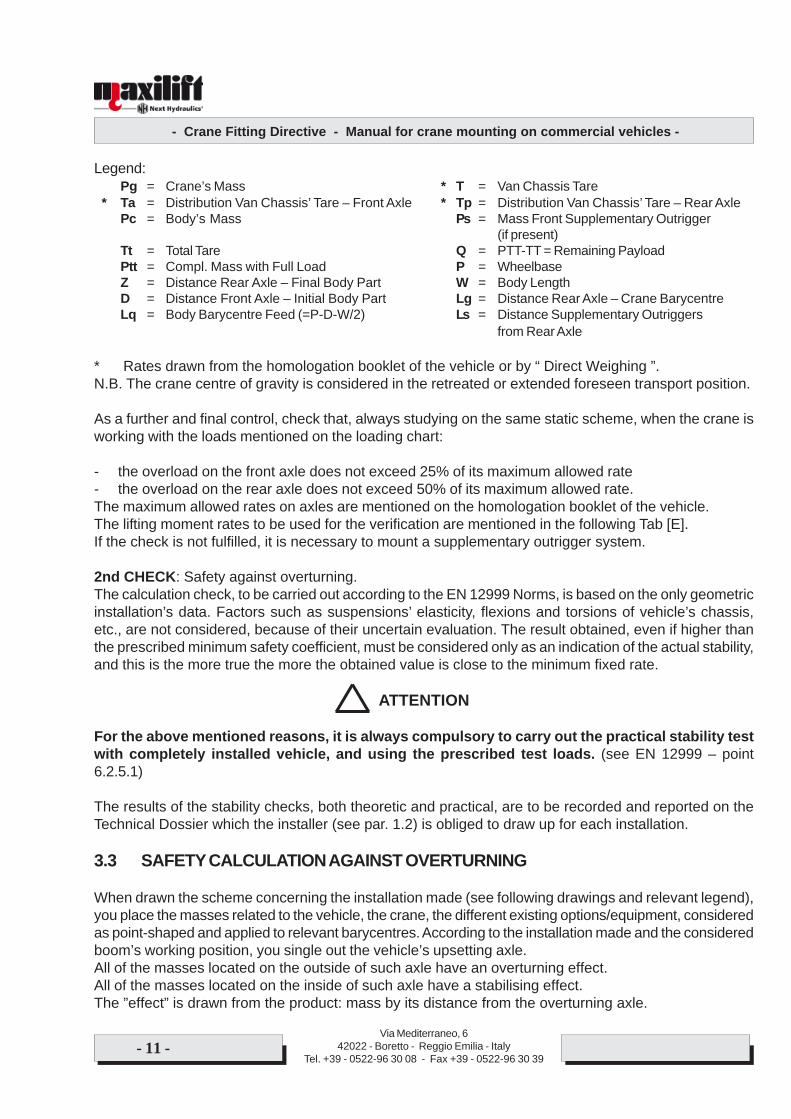
Legend:Pg = Crane’s Mass * T = Van Chassis Tare
* Ta = Distribution Van Chassis’ Tare – Front Axle * Tp = Distribution Van Chassis’ Tare – Rear AxlePc = Body’s Mass Ps = Mass Front Supplementary Outrigger
(if present)Tt = Total Tare Q = PTT-TT = Remaining PayloadPtt = Compl. Mass with Full Load P = WheelbaseZ = Distance Rear Axle – Final Body Part W = Body LengthD = Distance Front Axle – Initial Body Part Lg = Distance Rear Axle – Crane BarycentreLq = Body Barycentre Feed (=P-D-W/2) Ls = Distance Supplementary Outriggers
from Rear Axle
* Rates drawn from the homologation booklet of the vehicle or by “ Direct Weighing ”.N.B. The crane centre of gravity is considered in the retreated or extended foreseen transport position.
As a further and final control, check that, always studying on the same static scheme, when the crane isworking with the loads mentioned on the loading chart:
- the overload on the front axle does not exceed 25% of its maximum allowed rate- the overload on the rear axle does not exceed 50% of its maximum allowed rate.The maximum allowed rates on axles are mentioned on the homologation booklet of the vehicle.The lifting moment rates to be used for the verification are mentioned in the following Tab [E].If the check is not fulfilled, it is necessary to mount a supplementary outrigger system.
2nd CHECK: Safety against overturning.The calculation check, to be carried out according to the EN 12999 Norms, is based on the only geometricinstallation’s data. Factors such as suspensions’ elasticity, flexions and torsions of vehicle’s chassis,etc., are not considered, because of their uncertain evaluation. The result obtained, even if higher thanthe prescribed minimum safety coefficient, must be considered only as an indication of the actual stability,and this is the more true the more the obtained value is close to the minimum fixed rate.
ATTENTION
For the above mentioned reasons, it is always compulsory to carry out the practical stability testwith completely installed vehicle, and using the prescribed test loads. (see EN 12999 – point6.2.5.1)
The results of the stability checks, both theoretic and practical, are to be recorded and reported on theTechnical Dossier which the installer (see par. 1.2) is obliged to draw up for each installation.
3.3 SAFETY CALCULATION AGAINST OVERTURNING
When drawn the scheme concerning the installation made (see following drawings and relevant legend),you place the masses related to the vehicle, the crane, the different existing options/equipment, consideredas point-shaped and applied to relevant barycentres. According to the installation made and the consideredboom’s working position, you single out the vehicle’s upsetting axle.All of the masses located on the outside of such axle have an overturning effect.All of the masses located on the inside of such axle have a stabilising effect.The ”effect” is drawn from the product: mass by its distance from the overturning axle.
- Crane Fitting Directive - Manual for crane mounting on commercial vehicles -
Via Mediterraneo, 642022 - Boretto - Reggio Emilia - Italy
Tel. +39 - 0522-96 30 08 - Fax +39 - 0522-96 30 39- 12 -
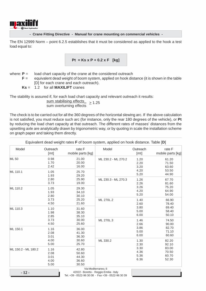
The EN 12999 Norm – point 6.2.5 establishes that it must be considered as applied to the hook a testload equal to:
Pt = Ks x P + 0.2 x F [kg]
where: P = load chart capacity of the crane at the considered outreachF = equivalent dead weight of boom system, applied on hook distance (it is shown in the table
[D] for each crane and each outreach). Ks = 1.2 for all MAXILIFT cranes
The stability is assured if, for each load chart capacity and relevant outreach it results:sum stabilising effects_sum overturning effects
The check is to be carried out for all the 360 degrees of the horizontal slewing arc. If the above calculationis not satisfied, you must reduce such arc (for instance, only the rear 180 degrees of the vehicle), or Ptby reducing the load chart capacity at that outreach. The different rates of masses’ distances from theupsetting axle are analytically drawn by trigonometric way, or by quoting in scale the installation schemeon graph paper and taking them directly.
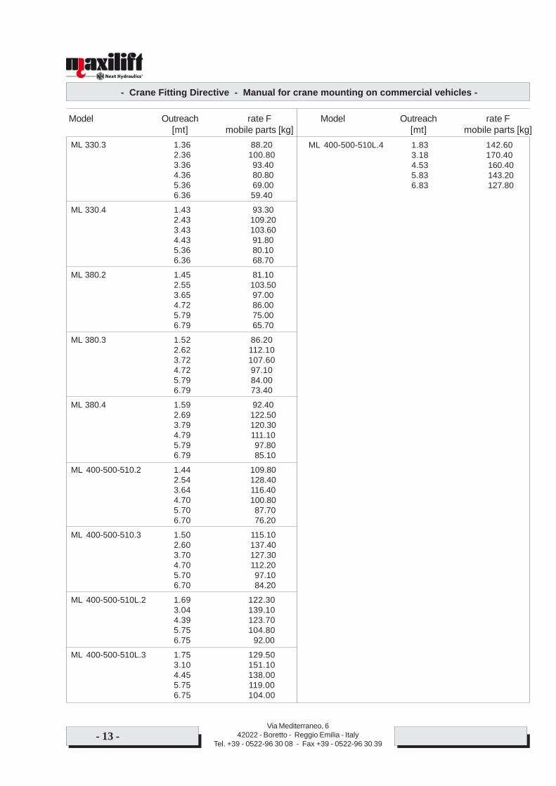
Equivalent dead weight rates F of boom system, applied on hook distance. Table [D]
Model Outreach rate F Model Outreach rate F[mt] mobile parts [kg] [mt] mobile parts [kg]
ML 50 0.98 21.001.70 20.002.42 16.00
ML 110.1 1.05 25.701.93 29.202.80 25.903.73 19.00
ML 110.2 1.05 29.301.93 34.102.80 30.103.73 25.204.50 21.60
ML 110.3 1.10 31.601.98 38.302.85 35.103.73 30.004.50 25.60
ML 150.1 1.16 36.002.08 41.303.01 36.304.00 30.605.00 25.70
ML 150.2 - ML 180.2 1.16 42.802.08 50.603.01 44.304.00 36.605.00 30.50
ML 230.2 - ML 270.2 1.20 61.202.20 71.503.20 63.604.20 53.505.20 44.90
ML 230.3 - ML 270.3 1.26 67.702.26 81.603.26 75.204.20 64.905.20 54.00
ML 270L.2 1.40 66.902.60 78.403.80 69.405.00 58.406.00 50.10
ML 270L.3 1.46 74.502.66 90.003.86 82.705.00 71.106.00 60.60
ML 330.2 1.30 82.202.30 92.103.30 83.004.36 70.505.36 60.706.36 52.30
> 1.25
- Crane Fitting Directive - Manual for crane mounting on commercial vehicles -
Via Mediterraneo, 642022 - Boretto - Reggio Emilia - Italy
Tel. +39 - 0522-96 30 08 - Fax +39 - 0522-96 30 39- 13 -
ML 330.3 1.36 88.202.36 100.803.36 93.404.36 80.805.36 69.006.36 59.40
ML 330.4 1.43 93.302.43 109.203.43 103.604.43 91.805.36 80.106.36 68.70
ML 380.2 1.45 81.102.55 103.503.65 97.004.72 86.005.79 75.006.79 65.70
ML 380.3 1.52 86.202.62 112.103.72 107.604.72 97.105.79 84.006.79 73.40
ML 380.4 1.59 92.402.69 122.503.79 120.304.79 111.105.79 97.806.79 85.10
ML 400-500-510.2 1.44 109.802.54 128.403.64 116.404.70 100.805.70 87.706.70 76.20
ML 400-500-510.3 1.50 115.102.60 137.403.70 127.304.70 112.205.70 97.106.70 84.20
ML 400-500-510L.2 1.69 122.303.04 139.104.39 123.705.75 104.806.75 92.00
ML 400-500-510L.3 1.75 129.503.10 151.104.45 138.005.75 119.006.75 104.00
Model Outreach rate F Model Outreach rate F[mt] mobile parts [kg] [mt] mobile parts [kg]
ML 400-500-510L.4 1.83 142.603.18 170.404.53 160.405.83 143.206.83 127.80
- Crane Fitting Directive - Manual for crane mounting on commercial vehicles -
Via Mediterraneo, 642022 - Boretto - Reggio Emilia - Italy
Tel. +39 - 0522-96 30 08 - Fax +39 - 0522-96 30 39- 14 -
3.4 DIMENSIONING OF REINFORCING CHASSIS FRAME
As the crane is to be solidly fixed to the vehicle’s chassis (see following Chapt. 4), this one comes to besubjected to very high stresses, not foreseen by the truck Manufacturer. Therefore, it is generally essentialto stiffen the chassis by a supplementary reinforcing structure called “reinforcing chassis counter-fra-me”. Apart from its constructive conditions for the moment (see following par. 3.5), first it is to be determined:1 - size of the section (and its mass for line meter)2 - materialthat the reinforcing chassis must have to avoiding damaging of vehicle’s chassis, and in order to estimat-ing the additional reinforcing chassis’ mass (necessary for the calculation of loads on the axles andvehicle’s stability). The following calculation is conform to CUNA NC 034-05 Regulation.
ATTENTION
The following calculation method does not replace the prescriptions of the truck Manufacturer,which are indicated on its “INSTALLATION INSTRUCTIONS”. Such prescriptions must anywaybe respected. May a discordance arise between “INSTALLATION INSTRUCTIONS” and thefollowing calculation, always apply the most conservative results.
3.4.1 Reinforcing chassis calculation
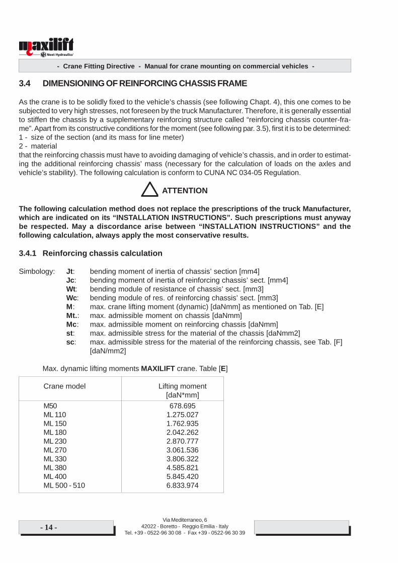
Simbology: Jt: bending moment of inertia of chassis’ section [mm4]Jc: bending moment of inertia of reinforcing chassis’ sect. [mm4]Wt: bending module of resistance of chassis’ sect. [mm3]Wc: bending module of res. of reinforcing chassis’ sect. [mm3]M: max. crane lifting moment (dynamic) [daNmm] as mentioned on Tab. [E]Mt.: max. admissible moment on chassis [daNmm]Mc: max. admissible moment on reinforcing chassis [daNmm]st: max. admissible stress for the material of the chassis [daNmm2]sc: max. admissible stress for the material of the reinforcing chassis, see Tab. [F]
[daN/mm2]
Max. dynamic lifting moments MAXILIFT crane. Table [E]
Crane model Lifting moment[daN*mm]
M50 678.695ML 110 1.275.027ML 150 1.762.935ML 180 2.042.262ML 230 2.870.777ML 270 3.061.536ML 330 3.806.322ML 380 4.585.821ML 400 5.845.420ML 500 - 510 6.833.974

- Crane Fitting Directive - Manual for crane mounting on commercial vehicles -
Via Mediterraneo, 642022 - Boretto - Reggio Emilia - Italy
Tel. +39 - 0522-96 30 08 - Fax +39 - 0522-96 30 39- 15 -
3.4.2 Materials for reinforcing chassis
Use exclusively structural steel. Make sure that the quality chosen is actually supplied, even asking themilling certificates.
STEEL TYPES COMMONLY USED FOR REINFORCING CHASSIS Tab. [F]
Standard EN 10025 Standard UNI 7070 Ultimate strength Admissible stress sc[daN/mm2] [daN/mm2]
Fe E 235 Fe 360 >= 36 16Fe E 275 Fe 430 >= 43 18.3Fe E 355 Fe 510 >= 52 24
For other steel types ask previously Next Hydraulics.
3.4.3 Reinforcing chassis calculation
First it is to be checked that the reinforcing chassis is actually needed in the specific case. When thecrane is very small in relation to the truck where it is mounted, the vehicle’s chassis may suffice to bearcrane stresses. If:
s = M / 2*Wt < st
then we are in such case. The vehicle’s chassis is in itself sufficient, only a stress distribution plate ofproper length between crane and chassis is required (see par. 3.5).
Otherwise, the verification takes two different ways according to the fact that:
A) the crane is installed behind the cabB) the crane is installed rear body.
A) CRANE INSTALLED BEHIND THE CABThe dynamic moment of the crane is to be split up in parts proportional to the moments of inertia of thechassis’ and reinforcing chassis’ sections, by imposing the following equations:
Mt = 2st*Wt Mc = M-Mt
The following relations must be simultaneously verified:
Jc >= Mc*Jt/Mt Wc >= Mc/2sc
If not so, the calculation is to be repeated by adopting a different reinforcing chassis’ section (with biggerthickness or height).
- Crane Fitting Directive - Manual for crane mounting on commercial vehicles -
Via Mediterraneo, 642022 - Boretto - Reggio Emilia - Italy
Tel. +39 - 0522-96 30 08 - Fax +39 - 0522-96 30 39- 16 -
B) CRANE INSTALLED REAR BODY (= on the rear overhang of the truck)The building of the reinforcing chassis is more complicated and exacting, because it is to be carried outso that it forms one only structure with the vehicle’s chassis, with a suitable contrast in bending andtorsion (see foll. par. 3.5).Considering: J = bending moment of inertia of the global section formed by the chassis’ and rein-
forcing chassis’ sections, considered as all in one [mm4]Zsup, Zinf = distances of the extreme borders of the reinforcing chassis and the chassis
from the centre of gravity of the global section [mm]
Wsup = J / Zsup [mm³] , Winf = J / Zinf [mm³]
The calculation is verified if:
Wsup >= M / (2*st) , Winf >= M / (2*sc)
If not so, the calculation must be repeated choosing a different reinforcing chassis’ section (with biggerthickness or height).
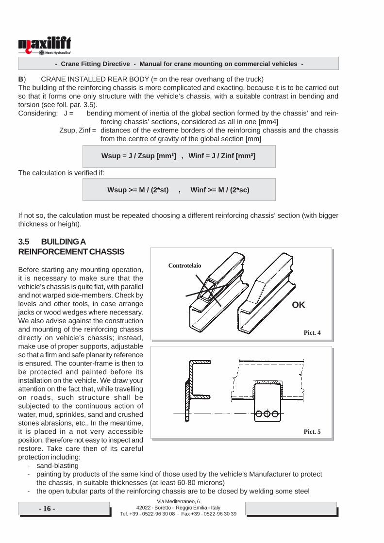
3.5 BUILDING AREINFORCEMENT CHASSIS
Before starting any mounting operation,it is necessary to make sure that thevehicle’s chassis is quite flat, with paralleland not warped side-members. Check bylevels and other tools, in case arrangejacks or wood wedges where necessary.We also advise against the constructionand mounting of the reinforcing chassisdirectly on vehicle’s chassis; instead,make use of proper supports, adjustableso that a firm and safe planarity referenceis ensured. The counter-frame is then tobe protected and painted before itsinstallation on the vehicle. We draw yourattention on the fact that, while travellingon roads, such structure shall besubjected to the continuous action ofwater, mud, sprinkles, sand and crushedstones abrasions, etc.. In the meantime,it is placed in a not very accessibleposition, therefore not easy to inspect andrestore. Take care then of its carefulprotection including:
- sand-blasting- painting by products of the same kind of those used by the vehicle’s Manufacturer to protect
the chassis, in suitable thicknesses (at least 60-80 microns)- the open tubular parts of the reinforcing chassis are to be closed by welding some steel
Pict. 5
Pict. 4
Controtelaio
OK
- Crane Fitting Directive - Manual for crane mounting on commercial vehicles -
Via Mediterraneo, 642022 - Boretto - Reggio Emilia - Italy
Tel. +39 - 0522-96 30 08 - Fax +39 - 0522-96 30 39- 17 -
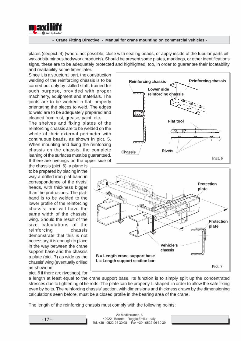
plates (seepict. 4) (where not possible, close with sealing beads, or apply inside of the tubular parts oil-wax or bituminous bodywork products). Should be present some plates, markings, or other identificationssigns, these are to be adequately protected and highlighted, too, in order to guarantee their locatabilityand readability some times later.Since it is a structural part, the constructionwelding of the reinforcing chassis is to becarried out only by skilled staff, trained forsuch purpose, provided with propermachinery, equipment and materials. Thejoints are to be worked in flat, properlyorientating the pieces to weld. The edgesto weld are to be adequately prepared andcleaned from rust, grease, paint, etc.The shelves and fixing plates of thereinforcing chassis are to be welded on thewhole of their external perimeter withcontinuous beads, as shown in pict. 5.When mounting and fixing the reinforcingchassis on the chassis, the completeleaning of the surfaces must be guaranteed.If there are rivetings on the upper side ofthe chassis (pict. 6), a plane isto be prepared by placing in theway a drilled iron plat-band incorrespondence of the rivets’heads, with thickness biggerthan the protrusions. The plat-band is to be welded to thelower profile of the reinforcingchassis, and will have thesame width of the chassis’wing. Should the result of thesize calculations of thereinforcing chassisdemonstrate that this is notnecessary, it is enough to placein the way between the cranesupport base and the chassisa plate (pict. 7) as wide as thechassis’ wing (eventually drilledas shown inpict. 6 if there are rivetings), fora length at least equal to the crane support base. Its function is to simply split up the concentratedstresses due to tightening of tie rods. The plate can be properly L-shaped, in order to allow the safe fixingeven by bolts. The reinforcing chassis’ section, with dimensions and thickness drawn by the dimensioningcalculations seen before, must be a closed profile in the bearing area of the crane.
The length of the reinforcing chassis must comply with the following points:
Pict. 6
Flat tool
Rivets
Reinforcing chassis
Chassis
Reinforcing chassis
Lower sidereinforcing chassis
Pict. 6
Pict. 7
Protectionplate
Protectionplate
Vehicle’schassis
B
B = Length crane support baseL = Length support section bar
- Crane Fitting Directive - Manual for crane mounting on commercial vehicles -
Via Mediterraneo, 642022 - Boretto - Reggio Emilia - Italy
Tel. +39 - 0522-96 30 08 - Fax +39 - 0522-96 30 39- 18 -
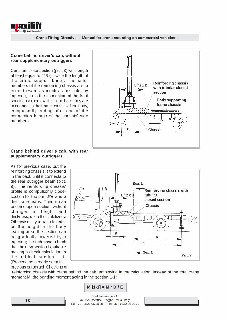
Crane behind driver’s cab, withoutrear supplementary outriggers
Constant close-section (pict. 8) with lengthat least equal to 2*B (= twice the length ofthe crane support base). The side-members of the reinforcing chassis are tocome forward as much as possible, bytapering, up to the connection of the frontshock absorbers, whilst in the back they areto connect to the frame chassis of the body,compulsorily ending after one of theconnection beams of the chassis’ sidemembers.
Crane behind driver’s cab, with rearsupplementary outriggers
As for previous case, but thereinforcing chassis is to extendin the back until it connects tothe rear outrigger beam (pict.9). The reinforcing chassis’profile is compulsorily close-section for the part 2*B wherethe crane leans. Then it canbecome open-section, withoutchanges in height andthickness, up to the stabilizers.Otherwise, if you wish to redu-ce the height in the bodyleaning area, the section canbe gradually lowered by atapering; in such case, checkthat the new section is suitablemaking a check calculation inthe critical section 1-1.(Proceed as already seen inprevious paragraph Checking of reinforcing chassis with crane behind the cab, employing in the calculation, instead of the total cranemoment M, the bending moment acting in the section 1-1:
M [1-1] = M * D / E
Reinforcing chassiswith tubular closedsection
L > 2 x B
B
Body supportingframe chassis
Chassis
Pict. 9
L > 2 x B
B
Chassis
Reinforcing chassis withtubularclosed section
D
E
Sez. 1
Sez. 1
- Crane Fitting Directive - Manual for crane mounting on commercial vehicles -
Via Mediterraneo, 642022 - Boretto - Reggio Emilia - Italy
Tel. +39 - 0522-96 30 08 - Fax +39 - 0522-96 30 39- 19 -
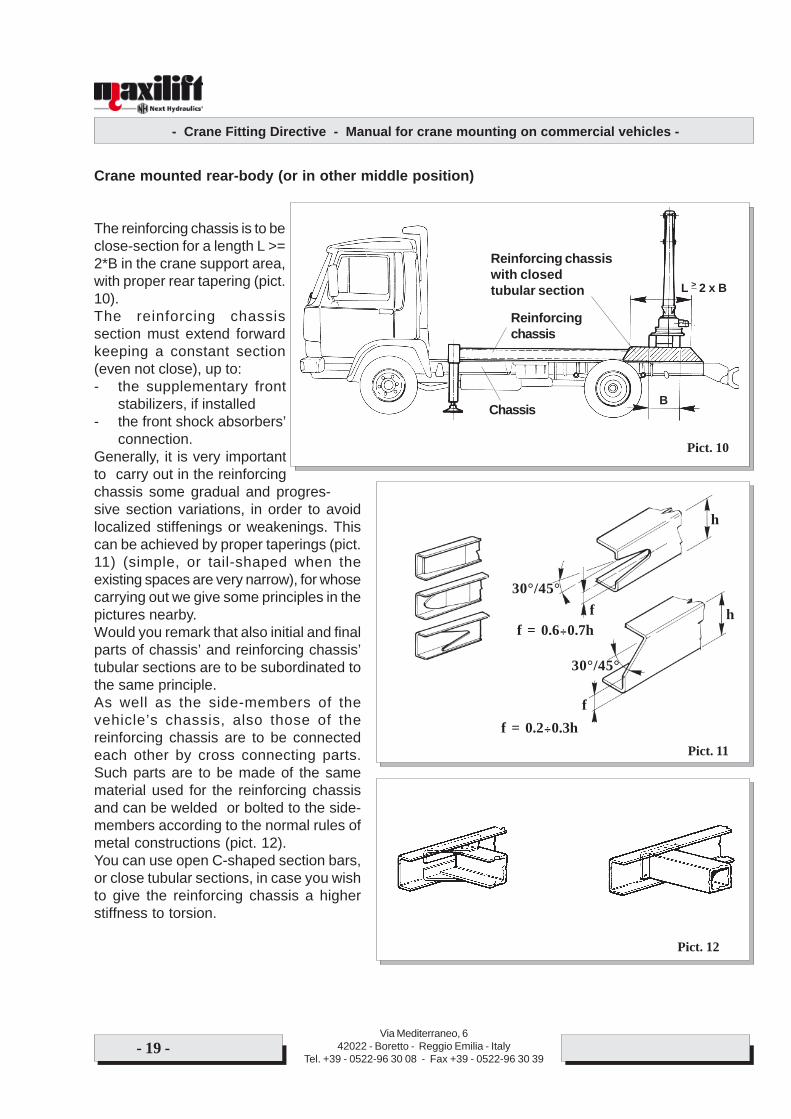
Crane mounted rear-body (or in other middle position)
The reinforcing chassis is to beclose-section for a length L >=2*B in the crane support area,with proper rear tapering (pict.10).The reinforcing chassissection must extend forwardkeeping a constant section(even not close), up to:- the supplementary front
stabilizers, if installed- the front shock absorbers’
connection.Generally, it is very importantto carry out in the reinforcingchassis some gradual and progres-sive section variations, in order to avoidlocalized stiffenings or weakenings. Thiscan be achieved by proper taperings (pict.11) (simple, or tail-shaped when theexisting spaces are very narrow), for whosecarrying out we give some principles in thepictures nearby.Would you remark that also initial and finalparts of chassis’ and reinforcing chassis’tubular sections are to be subordinated tothe same principle.As well as the side-members of thevehicle’s chassis, also those of thereinforcing chassis are to be connectedeach other by cross connecting parts.Such parts are to be made of the samematerial used for the reinforcing chassisand can be welded or bolted to the side-members according to the normal rules ofmetal constructions (pict. 12).You can use open C-shaped section bars,or close tubular sections, in case you wishto give the reinforcing chassis a higherstiffness to torsion.
h
hf
f
30°/45°
30°/45°
f = 0.6÷0.7h
f = 0.2÷0.3hPict. 11
Pict. 12
Pict. 10
L > 2 x B
B
Reinforcingchassis
Reinforcing chassiswith closedtubular section
Chassis
- Crane Fitting Directive - Manual for crane mounting on commercial vehicles -
Via Mediterraneo, 642022 - Boretto - Reggio Emilia - Italy
Tel. +39 - 0522-96 30 08 - Fax +39 - 0522-96 30 39- 20 -
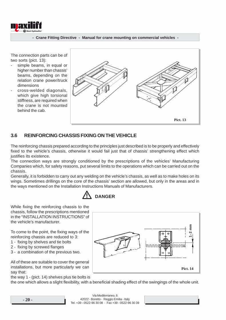
The connection parts can be oftwo sorts (pict. 13):- simple beams, in equal or
higher number than chassis’beams, depending on therelation crane power/truckdimensions
- cross-welded diagonals,which give high torsionalstiffness, are required whenthe crane is not mountedbehind the cab.
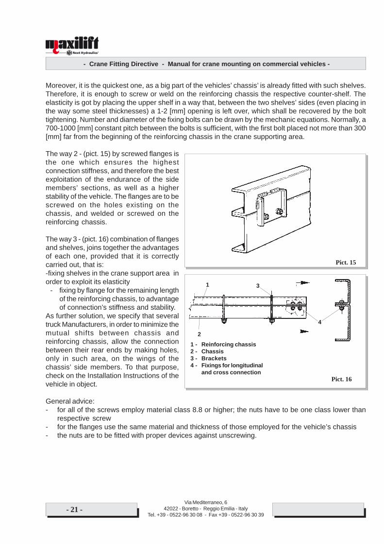
3.6 REINFORCING CHASSIS FIXING ON THE VEHICLE
The reinforcing chassis prepared according to the principles just described is to be properly and effectivelyfixed to the vehicle’s chassis, otherwise it would fail just that of chassis’ strengthening effect whichjustifies its existence.The connection ways are strongly conditioned by the prescriptions of the vehicles’ ManufacturingCompanies which, for safety reasons, put several limits to the operations which can be carried out on thechassis.Generally, it is forbidden to carry out any welding on the vehicle’s chassis, as well as to make holes on itswings. Sometimes drillings on the core of the chassis’ section are allowed, but only in the areas and inthe ways mentioned on the Installation Instructions Manuals of Manufacturers.
DANGER
While fixing the reinforcing chassis to thechassis, follow the prescriptions mentionedin the “INSTALLATION INSTRUCTIONS” ofthe vehicle’s manufacturer.
To come to the point, the fixing ways of thereinforcing chassis are reduced to 3:1 - fixing by shelves and tie bolts2 - fixing by screwed flanges3 - a combination of the previous two.
All of these are suitable to cover the generalinstallations, but more particularly we cansay that:the way 1 - (pict. 14) shelves plus tie bolts isthe one which allows a slight flexibility, with a beneficial shading effect of the swingings of the whole unit.
!
Pict. 13
Pict. 14
1÷2
mm
- Crane Fitting Directive - Manual for crane mounting on commercial vehicles -
Via Mediterraneo, 642022 - Boretto - Reggio Emilia - Italy
Tel. +39 - 0522-96 30 08 - Fax +39 - 0522-96 30 39- 21 -
Moreover, it is the quickest one, as a big part of the vehicles’ chassis’ is already fitted with such shelves.Therefore, it is enough to screw or weld on the reinforcing chassis the respective counter-shelf. Theelasticity is got by placing the upper shelf in a way that, between the two shelves’ sides (even placing inthe way some steel thicknesses) a 1-2 [mm] opening is left over, which shall be recovered by the bolttightening. Number and diameter of the fixing bolts can be drawn by the mechanic equations. Normally, a700-1000 [mm] constant pitch between the bolts is sufficient, with the first bolt placed not more than 300[mm] far from the beginning of the reinforcing chassis in the crane supporting area.
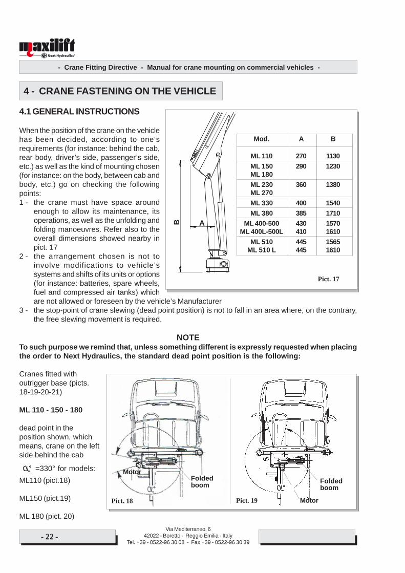
The way 2 - (pict. 15) by screwed flanges isthe one which ensures the highestconnection stiffness, and therefore the bestexploitation of the endurance of the sidemembers’ sections, as well as a higherstability of the vehicle. The flanges are to bescrewed on the holes existing on thechassis, and welded or screwed on thereinforcing chassis.
The way 3 - (pict. 16) combination of flangesand shelves, joins together the advantagesof each one, provided that it is correctlycarried out, that is:-fixing shelves in the crane support area inorder to exploit its elasticity
- fixing by flange for the remaining lengthof the reinforcing chassis, to advantageof connection’s stiffness and stability.
As further solution, we specify that severaltruck Manufacturers, in order to minimize themutual shifts between chassis andreinforcing chassis, allow the connectionbetween their rear ends by making holes,only in such area, on the wings of thechassis’ side members. To that purpose,check on the Installation Instructions of thevehicle in object.
General advice:- for all of the screws employ material class 8.8 or higher; the nuts have to be one class lower than
respective screw- for the flanges use the same material and thickness of those employed for the vehicle’s chassis- the nuts are to be fitted with proper devices against unscrewing.
Pict. 15
Pict. 16
1
2
4
3
1 - Reinforcing chassis2 - Chassis3 - Brackets4 - Fixings for longitudinal
and cross connection
- Crane Fitting Directive - Manual for crane mounting on commercial vehicles -
Via Mediterraneo, 642022 - Boretto - Reggio Emilia - Italy
Tel. +39 - 0522-96 30 08 - Fax +39 - 0522-96 30 39- 22 -
4 - CRANE FASTENING ON THE VEHICLE
4.1 GENERAL INSTRUCTIONS
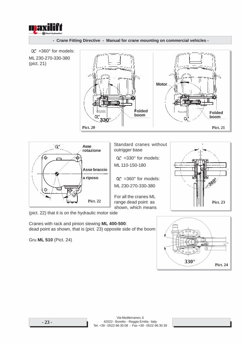
When the position of the crane on the vehiclehas been decided, according to one’srequirements (for instance: behind the cab,rear body, driver’s side, passenger’s side,etc.) as well as the kind of mounting chosen(for instance: on the body, between cab andbody, etc.) go on checking the followingpoints:1 - the crane must have space around
enough to allow its maintenance, itsoperations, as well as the unfolding andfolding manoeuvres. Refer also to theoverall dimensions showed nearby inpict. 17
2 - the arrangement chosen is not toinvolve modifications to vehicle’ssystems and shifts of its units or options(for instance: batteries, spare wheels,fuel and compressed air tanks) whichare not allowed or foreseen by the vehicle’s Manufacturer
3 - the stop-point of crane slewing (dead point position) is not to fall in an area where, on the contrary,the free slewing movement is required.
NOTETo such purpose we remind that, unless something different is expressly requested when placingthe order to Next Hydraulics, the standard dead point position is the following:
Cranes fitted withoutrigger base (picts.18-19-20-21)
ML 110 - 150 - 180
dead point in theposition shown, whichmeans, crane on the leftside behind the cab
=330° for models:ML110 (pict.18)
ML150 (pict.19)
ML 180 (pict. 20)
Pict. 17
Mod. A B
ML 110 270 1130ML 150 290 1230ML 180ML 230 360 1380ML 270ML 330 400 1540ML 380 385 1710
ML 400-500 430 1570ML 400L-500L 410 1610
ML 510 445 1565ML 510 L 445 1610
B A
Pict. 19
Foldedboom
MotorPict. 18
Foldedboom
Motor
- Crane Fitting Directive - Manual for crane mounting on commercial vehicles -
Via Mediterraneo, 642022 - Boretto - Reggio Emilia - Italy
Tel. +39 - 0522-96 30 08 - Fax +39 - 0522-96 30 39- 23 -
=360° for models:ML 230-270-330-380(pict. 21)
Standard cranes withoutoutrigger base
=330° for models:ML 110-150-180
=360° for models:ML 230-270-330-380
For all the cranes MLrange dead point asshown, which means
(pict. 22) that it is on the hydraulic motor side
Cranes with rack and pinion slewing ML 400-500:dead point as shown, that is (pict. 23) opposite side of the boom
Gru ML 510 (Pict. 24)
Pict. 22
Asserotazione
Asse braccio
a riposo
Pict. 23
Pict. 21
Motor
Foldedboom
Foldedboom
Pict. 20
Pict. 24330°
- Crane Fitting Directive - Manual for crane mounting on commercial vehicles -
Via Mediterraneo, 642022 - Boretto - Reggio Emilia - Italy
Tel. +39 - 0522-96 30 08 - Fax +39 - 0522-96 30 39- 24 -
4.2 CHANGING THE DEAD POINT POSITION
If necessary, the dead point can be changed from its original position.
ATTENTIONBefore starting to change the dead point position, read carefully the following instructions andmake sure to have fully understood the whole procedure.
NEXT HYDRAULICS DOES NOT ACKNOWLEDGE ANY WARRANTY FOR DAMAGES CAUSEDBY NON-CORRECT OR CLUMSY RE-POSITIONING OF THE DEAD POINT.
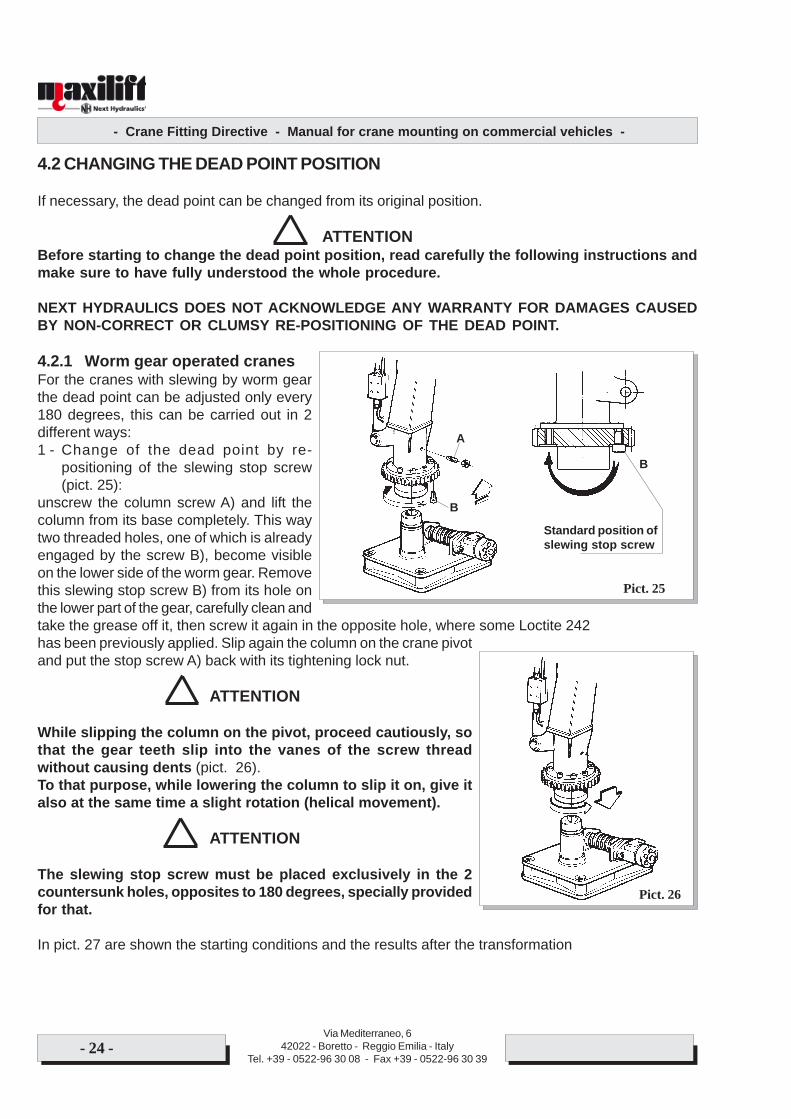
4.2.1 Worm gear operated cranesFor the cranes with slewing by worm gearthe dead point can be adjusted only every180 degrees, this can be carried out in 2different ways:1 - Change of the dead point by re-
positioning of the slewing stop screw(pict. 25):
unscrew the column screw A) and lift thecolumn from its base completely. This waytwo threaded holes, one of which is alreadyengaged by the screw B), become visibleon the lower side of the worm gear. Removethis slewing stop screw B) from its hole onthe lower part of the gear, carefully clean andtake the grease off it, then screw it again in the opposite hole, where some Loctite 242has been previously applied. Slip again the column on the crane pivotand put the stop screw A) back with its tightening lock nut.
ATTENTION
While slipping the column on the pivot, proceed cautiously, sothat the gear teeth slip into the vanes of the screw threadwithout causing dents (pict. 26).To that purpose, while lowering the column to slip it on, give italso at the same time a slight rotation (helical movement).
ATTENTION
The slewing stop screw must be placed exclusively in the 2countersunk holes, opposites to 180 degrees, specially providedfor that.
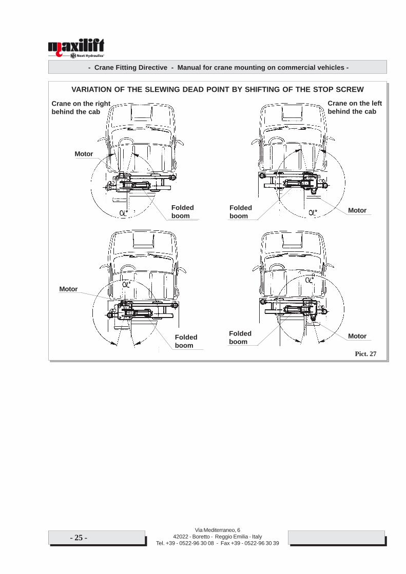
In pict. 27 are shown the starting conditions and the results after the transformation
Pict. 25
Standard position ofslewing stop screw
B
A
B
Pict. 26
- Crane Fitting Directive - Manual for crane mounting on commercial vehicles -
Via Mediterraneo, 642022 - Boretto - Reggio Emilia - Italy
Tel. +39 - 0522-96 30 08 - Fax +39 - 0522-96 30 39- 25 -
Pict. 27
VARIATION OF THE SLEWING DEAD POINT BY SHIFTING OF THE STOP SCREW
Crane on the rightbehind the cab
Crane on the leftbehind the cab
Motor
Foldedboom
MotorFoldedboom
MotorFoldedboomFolded
boom
Motor
- Crane Fitting Directive - Manual for crane mounting on commercial vehicles -
Via Mediterraneo, 642022 - Boretto - Reggio Emilia - Italy
Tel. +39 - 0522-96 30 08 - Fax +39 - 0522-96 30 39- 26 -
!
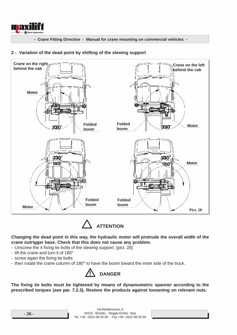
2 - Variation of the dead point by shifting of the slewing support
ATTENTION
Changing the dead point in this way, the hydraulic motor will protrude the overall width of thecrane outrigger base. Check that this does not cause any problem.- Unscrew the 4 fixing tie bolts of the slewing support (pict. 28)- lift the crane and turn it of 180°- screw again the fixing tie bolts- then rotate the crane column of 180° to have the boom toward the inner side of the truck.
DANGER
The fixing tie bolts must be tightened by means of dynamometric spanner according to theprescribed torques (see par. 7.2.3). Restore the products against loosening on relevant nuts.
Pict. 28
Crane on the rightbehind the cab
Crane on the leftbehind the cab
Motor
Foldedboom
FoldedboomMotor
MotorFoldedboom
Motor
Foldedboom
- Crane Fitting Directive - Manual for crane mounting on commercial vehicles -
Via Mediterraneo, 642022 - Boretto - Reggio Emilia - Italy
Tel. +39 - 0522-96 30 08 - Fax +39 - 0522-96 30 39- 27 -
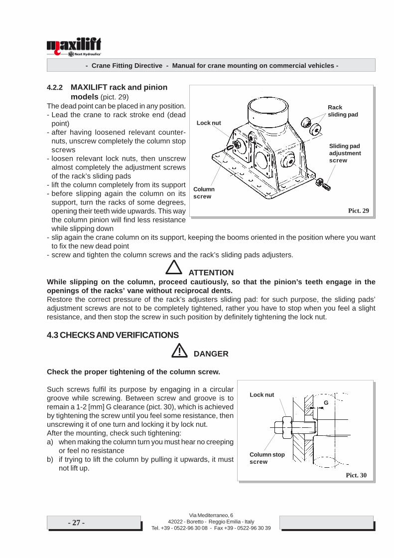
4.2.2 MAXILIFT rack and pinionmodels (pict. 29)
The dead point can be placed in any position.- Lead the crane to rack stroke end (dead
point)- after having loosened relevant counter-
nuts, unscrew completely the column stopscrews
- loosen relevant lock nuts, then unscrewalmost completely the adjustment screwsof the rack’s sliding pads
- lift the column completely from its support- before slipping again the column on its
support, turn the racks of some degrees,opening their teeth wide upwards. This waythe column pinion will find less resistancewhile slipping down
- slip again the crane column on its support, keeping the booms oriented in the position where you wantto fix the new dead point
- screw and tighten the column screws and the rack’s sliding pads adjusters.
ATTENTIONWhile slipping on the column, proceed cautiously, so that the pinion’s teeth engage in theopenings of the racks’ vane without reciprocal dents.Restore the correct pressure of the rack’s adjusters sliding pad: for such purpose, the sliding pads’adjustment screws are not to be completely tightened, rather you have to stop when you feel a slightresistance, and then stop the screw in such position by definitely tightening the lock nut.
4.3 CHECKS AND VERIFICATIONS
DANGER
Check the proper tightening of the column screw.
Such screws fulfil its purpose by engaging in a circulargroove while screwing. Between screw and groove is toremain a 1-2 [mm] G clearance (pict. 30), which is achievedby tightening the screw until you feel some resistance, thenunscrewing it of one turn and locking it by lock nut.After the mounting, check such tightening:a) when making the column turn you must hear no creeping
or feel no resistanceb) if trying to lift the column by pulling it upwards, it must
not lift up.
Pict. 29
Pict. 30
!
Racksliding pad
Sliding padadjustmentscrew
Columnscrew
Lock nut
Column stopscrew
Lock nutG
- Crane Fitting Directive - Manual for crane mounting on commercial vehicles -
Via Mediterraneo, 642022 - Boretto - Reggio Emilia - Italy
Tel. +39 - 0522-96 30 08 - Fax +39 - 0522-96 30 39- 28 -
! DANGER
Danger of hoses’ break. After carrying out the shifting of the dead point, check that the way ofthe hoses’ bundle from the crane base to the column originally provided by Next Hydraulics forthe standard configuration is still suitable to the new position of the column.The check is to be carried out by rotating, slowly and cautiously, up to the dead point, in both ways, andverifying that the hoses’ bundle regularly rolls and unrolls without getting entangled or creeping.
ATTENTION
All of the parts getting damaged during such operations (for instance: tie bolts, nuts, hoses,etc.) are to be replaced with original parts.

- Crane Fitting Directive - Manual for crane mounting on commercial vehicles -
Via Mediterraneo, 642022 - Boretto - Reggio Emilia - Italy
Tel. +39 - 0522-96 30 08 - Fax +39 - 0522-96 30 39- 29 -
- Crane Fitting Directive - Manual for crane mounting on commercial vehicles -
Via Mediterraneo, 642022 - Boretto - Reggio Emilia - Italy
Tel. +39 - 0522-96 30 08 - Fax +39 - 0522-96 30 39- 30 -
5 - CRANE CONNECTION
5.1 General information
The crane’s electric system is divided into two different parts:1 - one part concerning controls2 - one part <of power>, not always present, for which we refer to following par. 5.2.The electric power, 12V or 24V, required for the supply of the safety devices’ electrovalves and theswitchboard components (warning lights, key-switches, etc.) is to be drawn in the points, and accordingto the conditions stated by the vehicle’s Manufacturer in the relevant “Installation instructions”.Before starting work, make sure that the voltage of the vehicle’s electric system and the crane’s one arethe same.
IMPORTANT
On all of the covers and wrappings of the components of the crane’s electric system a plateshowing the working voltage is applied in a visible position.
DANGER
Before starting work, make sure that the vehicle and the crane have the same working voltage.
The damages caused to the crane’s electric system, and to its components, by the connection with awrong supply voltage are not acknowledged under warranty. The wiring diagrams of the different cranemodels and versions are shown in their relevant use and maintenance manuals. We hereby recall somebasic points:1 - the current withdrawal is to be placed under the vehicle’s ignition key, properly protected by a suitable
fuse2 - the fuse must be placed in a position easily accessible for its checking and replacement. It is to be
clearly marked and identifiable, and its position must be made known to the user3 - the supply cables of crane’s circuit are clearly marked by the (+) and (-) symbols. Before the connection,
make sure of the polarities’ correspondence.
DANGER
Before carrying out the connections, make sure of the polarities of the cables.
The damages to the crane electric plant, and to its parts, caused by the inversion of the polarities are notacknowledged under warranty.
DANGER
Each welding operation or working by electro-tools is to be carried out with disconnected supplyand ground cables, in order to avoid the serious damaging of the existing electric and electronicmain parts.
!
!
!
- Crane Fitting Directive - Manual for crane mounting on commercial vehicles -
Via Mediterraneo, 642022 - Boretto - Reggio Emilia - Italy
Tel. +39 - 0522-96 30 08 - Fax +39 - 0522-96 30 39- 31 -
NOTESome Maxilift crane models are fitted with electronic load limiter.Description, wiring diagrams and instructions for load limiting device and its components’ setting: seethe instructions booklet MD0219.
5.2 CRANE’S POWER SUPPLY
As far as the service operation period of the crane is concerned, there are basically two possibilities:A - the typical working cycle foreseen for the crane is continuative, and therefore not limited to
short periodsB - the working cycle is not regular and short, with frequent interruptions whose duration are longer
that the working periods.It is important that a correct identification of the kind of service is made when ordering the crane toNext Hydraulics, as to the two above mentioned possibilities correspond two different versions of asame crane model:A - crane in hydraulic version (with P.T.O. and pump) for working cycle not limited to short periodsB - crane in electro-hydraulic version (with electric pump) for working cycle limited to short periods.
ATTENTION
In case of any doubt about the choice, ask Next Hydraulics, supplying the data about theforeseen usage.
5.2.1 Crane with working cycle not limited to short periodsThe power is to be supplied preferably from the vehicle’s gearbox, on whose casing there is ascrewed lid prepared for such purpose.
ATTENTION
Before carrying out any operation on the vehicle’s gearbox, always consult the“INSTALLATION INSTRUCTIONS” manual of the manufacturer.
The power is obtained by removing the lid and applying a gear set, called “power take off”, whichdrives an hydraulic pump that delivers the crane the hydraulic oil required for its operation, drawing itfrom the relevant oil tank.
- Crane Fitting Directive - Manual for crane mounting on commercial vehicles -
Via Mediterraneo, 642022 - Boretto - Reggio Emilia - Italy
Tel. +39 - 0522-96 30 08 - Fax +39 - 0522-96 30 39- 32 -
i x 628 x eCp x pmax
628 x eCp x pmax
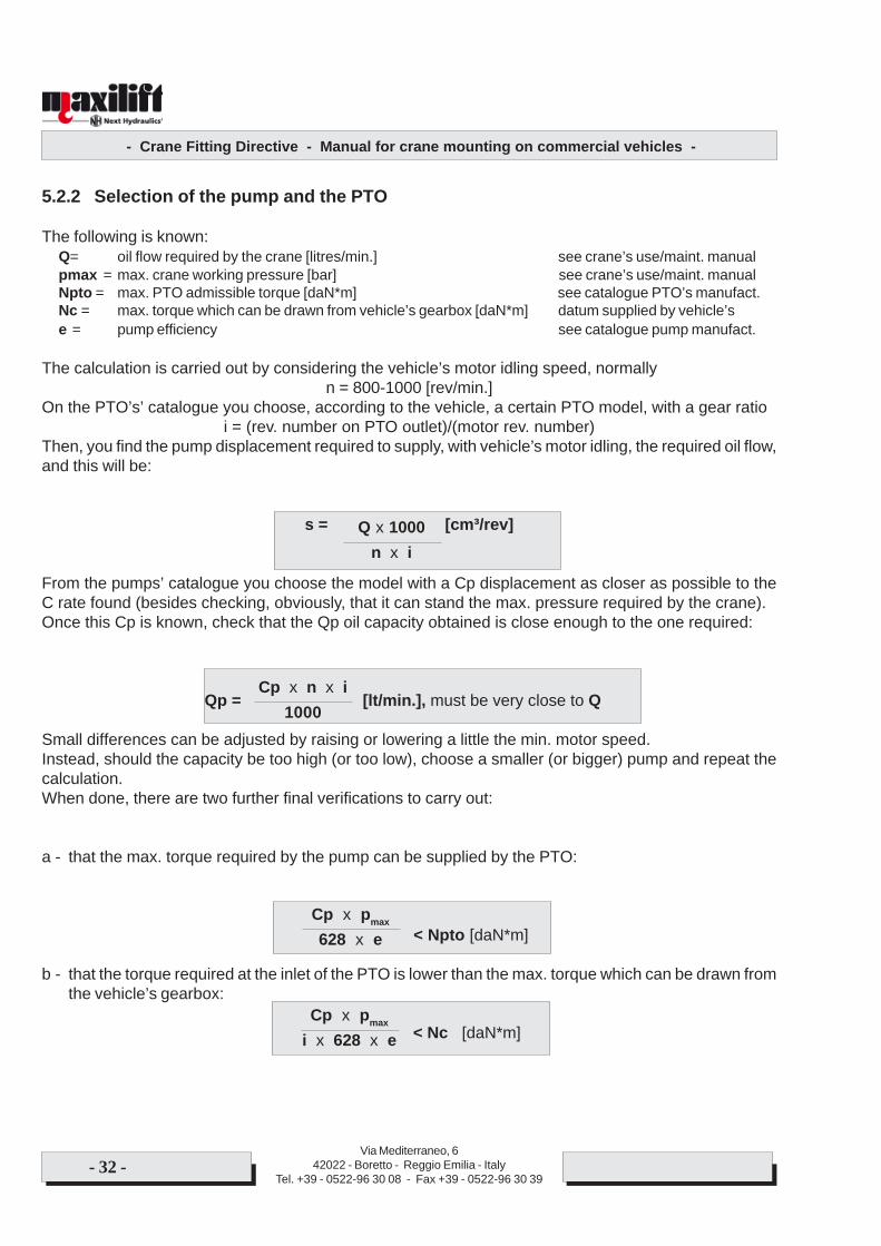
5.2.2 Selection of the pump and the PTO
The following is known:Q= oil flow required by the crane [litres/min.] see crane’s use/maint. manualpmax = max. crane working pressure [bar] see crane’s use/maint. manualNpto = max. PTO admissible torque [daN*m] see catalogue PTO’s manufact.Nc = max. torque which can be drawn from vehicle’s gearbox [daN*m] datum supplied by vehicle’se = pump efficiency see catalogue pump manufact.
The calculation is carried out by considering the vehicle’s motor idling speed, normallyn = 800-1000 [rev/min.]
On the PTO’s’ catalogue you choose, according to the vehicle, a certain PTO model, with a gear ratioi = (rev. number on PTO outlet)/(motor rev. number)
Then, you find the pump displacement required to supply, with vehicle’s motor idling, the required oil flow,and this will be:
s = [cm³/rev]
From the pumps’ catalogue you choose the model with a Cp displacement as closer as possible to theC rate found (besides checking, obviously, that it can stand the max. pressure required by the crane).Once this Cp is known, check that the Qp oil capacity obtained is close enough to the one required:
Qp = [lt/min.], must be very close to Q
Small differences can be adjusted by raising or lowering a little the min. motor speed.Instead, should the capacity be too high (or too low), choose a smaller (or bigger) pump and repeat thecalculation.When done, there are two further final verifications to carry out:
a - that the max. torque required by the pump can be supplied by the PTO:
< Npto [daN*m]
b - that the torque required at the inlet of the PTO is lower than the max. torque which can be drawn fromthe vehicle’s gearbox:
< Nc [daN*m]
n x iQ x 1000
1000Cp x n x i
- Crane Fitting Directive - Manual for crane mounting on commercial vehicles -
Via Mediterraneo, 642022 - Boretto - Reggio Emilia - Italy
Tel. +39 - 0522-96 30 08 - Fax +39 - 0522-96 30 39- 33 -
DANGER
If the pump flow is not the prescribed one (see chapt. 10 – technical data Use and maintenancemanual), the crane will not work correctly. Specifically, an oil flow greater than the prescribedone, besides causing a bad functioning of the hydraulic circuit (oil overheating), vibrations andcounter-pressures on valves and motors, causes too fast crane movements, and thereforedangers such as:
crane structure’s overloading because of dynamic effectslower metering of the loadslower stability of the vehicle.
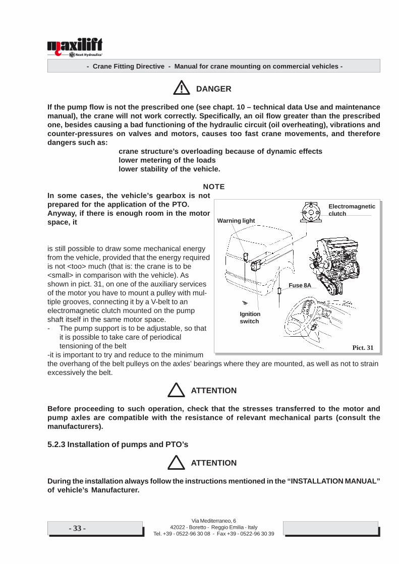
NOTEIn some cases, the vehicle’s gearbox is notprepared for the application of the PTO.Anyway, if there is enough room in the motorspace, it
is still possible to draw some mechanical energyfrom the vehicle, provided that the energy requiredis not <too> much (that is: the crane is to be<small> in comparison with the vehicle). Asshown in pict. 31, on one of the auxiliary servicesof the motor you have to mount a pulley with mul-tiple grooves, connecting it by a V-belt to anelectromagnetic clutch mounted on the pumpshaft itself in the same motor space.- The pump support is to be adjustable, so that
it is possible to take care of periodicaltensioning of the belt
-it is important to try and reduce to the minimumthe overhang of the belt pulleys on the axles’ bearings where they are mounted, as well as not to strainexcessively the belt.
ATTENTION
Before proceeding to such operation, check that the stresses transferred to the motor andpump axles are compatible with the resistance of relevant mechanical parts (consult themanufacturers).
5.2.3 Installation of pumps and PTO’s
ATTENTION
During the installation always follow the instructions mentioned in the “INSTALLATION MANUAL”of vehicle’s Manufacturer.
!
Pict. 31
Electromagneticclutch
Warning light
Ignitionswitch
Fuse 8A
- Crane Fitting Directive - Manual for crane mounting on commercial vehicles -
Via Mediterraneo, 642022 - Boretto - Reggio Emilia - Italy
Tel. +39 - 0522-96 30 08 - Fax +39 - 0522-96 30 39- 34 -
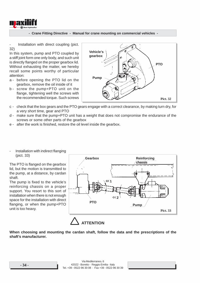
- Installation with direct coupling (pict.32)In this system, pump and PTO coupled bya stiff joint form one only body, and such unitis directly flanged on the proper gearbox lid.Without exhausting the matter, we herebyrecall some points worthy of particularattention:a - before opening the PTO lid on the
gearbox, remove the oil inside of itb - screw the pump+PTO unit on the
flange, tightening well the screws withthe recommended torque. Such screws
c - check that the box gears and the PTO gears engage with a correct clearance, by making turn dry, fora very short time, gear and PTO
d - make sure that the pump+PTO unit has a weight that does not compromise the endurance of thescrews or some other parts of the gearbox
e - after the work is finished, restore the oil level inside the gearbox.
- Installation with indirect flanging(pict. 33)
The PTO is flanged on the gearboxlid, but the motion is transmitted tothe pump, at a distance, by cardanshaft.The pump is fixed to the vehicle’sreinforcing chassis on a propersupport. You resort to this sort ofinstallation when there is not enoughspace for the installation with directflanging, or when the pump+PTOunit is too heavy.
ATTENTION
When choosing and mounting the cardan shaft, follow the data and the prescriptions of theshaft’s manufacturer.
Pict. 32
Pict. 33
Pump
PTO
Vehicle’sgearbox
Gearbox Reinforcingchassis
PTO Pump
2
1
- Crane Fitting Directive - Manual for crane mounting on commercial vehicles -
Via Mediterraneo, 642022 - Boretto - Reggio Emilia - Italy
Tel. +39 - 0522-96 30 08 - Fax +39 - 0522-96 30 39- 35 -
We hereby recall some basic points:- the pump is to be fixed to the reinforcing chassis in a way that its shaft has the same slope, referring
to the horizontal line, of the gear outlet shaft- when preparing the installation consider that, in order to prevent the pump damaging, the max. slope
of the cardan shaft compared with the pump axle must not exceed 9-10 degrees- the end forks of the cardan shaft are to lie on the same level (ALIGNED JOINTS), and to be leaning of
the same angle compared with the horizontal line (with reference to pict. 30: ALFA1 angle = ALFA2angle).
General instructions concerning the installation of pumps and PTO’s
1 - The pump inlet must always be installed <under oil level>, that is, its suction plug is to lie always at alower level than the hydraulic oil MINIMUM one in the tank
2 - While mounting, make sure that the outlet shaft of the PTO is subject only to a torsional stress. Avoidto mount on such shaft gears or pulleys, which would cause bendings. Use grooved joints axiallysliding, in order to prevent axial loads
3 - Make sure that the insertion times in full service given by the pump and PTO manufacturers arecompatible with the working periods foreseen for the crane
4 - While connecting the pump to the hydraulic system, follow the warnings mentioned in followingparagraph.
5.2.4 ontrols of the pump-PTO operation
ATTENTION
Pump and PTO must stay engaged exclusively for the only period of time strictly required foroperating the crane.
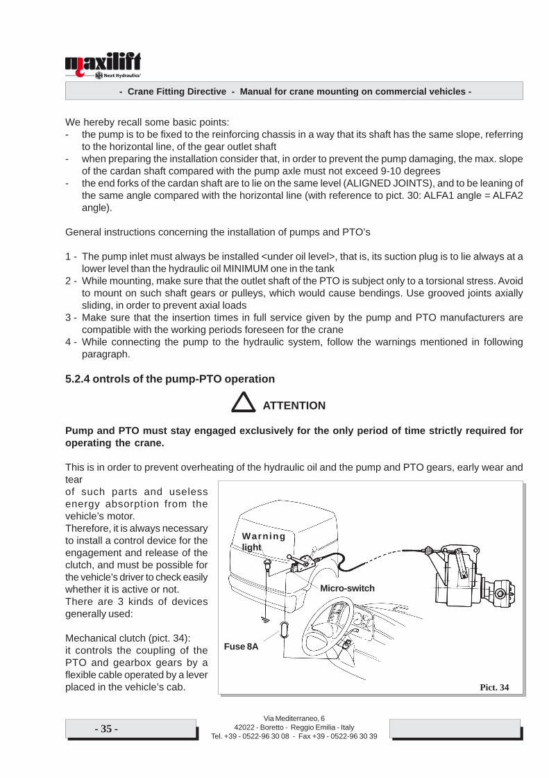
This is in order to prevent overheating of the hydraulic oil and the pump and PTO gears, early wear andtearof such parts and uselessenergy absorption from thevehicle’s motor.Therefore, it is always necessaryto install a control device for theengagement and release of theclutch, and must be possible forthe vehicle’s driver to check easilywhether it is active or not.There are 3 kinds of devicesgenerally used:
Mechanical clutch (pict. 34):it controls the coupling of thePTO and gearbox gears by aflexible cable operated by a leverplaced in the vehicle’s cab. Pict. 34
Fuse 8A
Warninglight
Micro-switch
- Crane Fitting Directive - Manual for crane mounting on commercial vehicles -
Via Mediterraneo, 642022 - Boretto - Reggio Emilia - Italy
Tel. +39 - 0522-96 30 08 - Fax +39 - 0522-96 30 39- 36 -
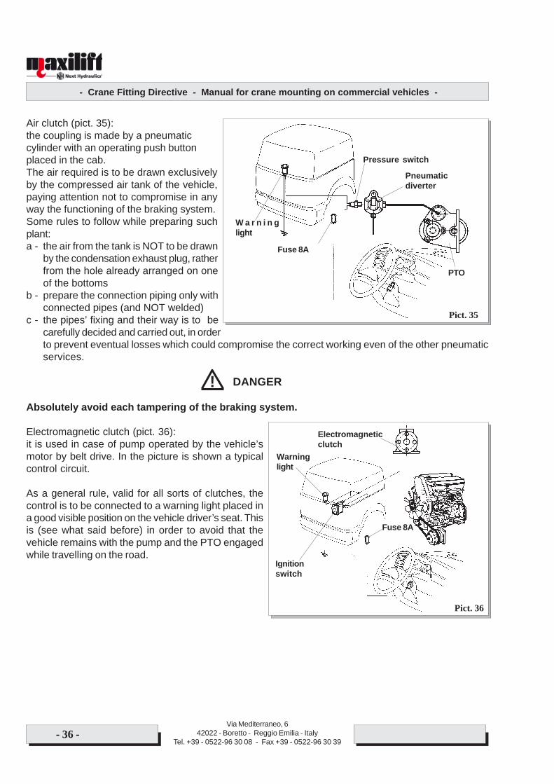
Air clutch (pict. 35):the coupling is made by a pneumaticcylinder with an operating push buttonplaced in the cab.The air required is to be drawn exclusivelyby the compressed air tank of the vehicle,paying attention not to compromise in anyway the functioning of the braking system.Some rules to follow while preparing suchplant:a - the air from the tank is NOT to be drawn
by the condensation exhaust plug, ratherfrom the hole already arranged on oneof the bottoms
b - prepare the connection piping only withconnected pipes (and NOT welded)
c - the pipes’ fixing and their way is to becarefully decided and carried out, in orderto prevent eventual losses which could compromise the correct working even of the other pneumaticservices.
DANGER
Absolutely avoid each tampering of the braking system.
Electromagnetic clutch (pict. 36):it is used in case of pump operated by the vehicle’smotor by belt drive. In the picture is shown a typicalcontrol circuit.
As a general rule, valid for all sorts of clutches, thecontrol is to be connected to a warning light placed ina good visible position on the vehicle driver’s seat. Thisis (see what said before) in order to avoid that thevehicle remains with the pump and the PTO engagedwhile travelling on the road.
!
Pict. 35
Pict. 36
PTO
Pneumaticdiverter
Pressure switch
W a r n i n glight
Fuse 8A
Electromagneticclutch
Warninglight
Ignitionswitch
Fuse 8A
- Crane Fitting Directive - Manual for crane mounting on commercial vehicles -
Via Mediterraneo, 642022 - Boretto - Reggio Emilia - Italy
Tel. +39 - 0522-96 30 08 - Fax +39 - 0522-96 30 39- 37 -
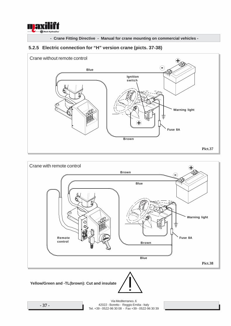
5.2.5 Electric connection for “H” version crane (picts. 37-38)
Crane without remote control
Crane with remote control
Yellow/Green and -TL(brown): Cut and insulate
Blue
Brown
+-
+Fuse 8A
Ignitionswitch
Warning light
+-Brown
Blue
Brown
Blue
Fuse 8A
Warning light
Remotecontrol
Pict.37
Pict.38
- Crane Fitting Directive - Manual for crane mounting on commercial vehicles -
Via Mediterraneo, 642022 - Boretto - Reggio Emilia - Italy
Tel. +39 - 0522-96 30 08 - Fax +39 - 0522-96 30 39- 38 -
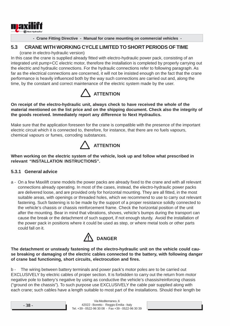
5.3 CRANE WITH WORKING CYCLE LIMITED TO SHORT PERIODS OF TIME(crane in electro-hydraulic version)
In this case the crane is supplied already fitted with electro-hydraulic power pack, consisting of anintegrated unit pump+CC electric motor, therefore the installation is completed by properly carrying outthe electric and hydraulic connections. For the hydraulic connections refer to following paragraph. Asfar as the electrical connections are concerned, it will not be insisted enough on the fact that the craneperformance is heavily influenced both by the way such connections are carried out and, along thetime, by the constant and correct maintenance of the electric system made by the user.
ATTENTION
On receipt of the electro-hydraulic unit, always check to have received the whole of thematerial mentioned on the list price and on the shipping document. Check also the integrity ofthe goods received. Immediately report any difference to Next Hydraulics.
Make sure that the application foreseen for the crane is compatible with the presence of the importantelectric circuit which it is connected to, therefore, for instance, that there are no fuels vapours,chemical vapours or fumes, corroding substances.
ATTENTION
When working on the electric system of the vehicle, look up and follow what prescribed inrelevant “INSTALLATION INSTRUCTIONS”.
5.3.1 General advice
a - On a few Maxilift crane models the power packs are already fixed to the crane and with all relevantconnections already operating. In most of the cases, instead, the electro-hydraulic power packsare delivered loose, and are provided only for horizontal mounting. They are all fitted, in the mostsuitable areas, with openings or threaded holes, which we recommend to use to carry out relevantfastening. Such fastening is to be made by the support of a proper resistance solidly connected tothe vehicle’s chassis or chassis reinforcement frame. Check the horizontal position of the unitafter the mounting. Bear in mind that vibrations, shoves, vehicle’s bumps during the transport cancause the break or the detachment of such support, if not enough sturdy. Avoid the installation ofthe power pack in positions where it could be used as step, or where metal tools or other partscould fall on it.
DANGER
The detachment or unsteady fastening of the electro-hydraulic unit on the vehicle could cau-se breaking or damaging of the electric cables connected to the battery, with following dangerof crane bad functioning, short circuits, electrocution and fires.
b - The wiring between battery terminals and power pack’s motor poles are to be carried outEXCLUSIVELY by electric cables of proper section. It is forbidden to carry out the return from motornegative pole to battery’s negative by using as conductive the vehicle’s chassis/reinforcing chassis(“ground on the chassis”). To such purpose use EXCLUSIVELY the cable pair supplied along witheach crane; such cables have a length suitable to most part of the installations. Should their length be
!
- Crane Fitting Directive - Manual for crane mounting on commercial vehicles -
Via Mediterraneo, 642022 - Boretto - Reggio Emilia - Italy
Tel. +39 - 0522-96 30 08 - Fax +39 - 0522-96 30 39- 39 -
insufficient (keep anyway their length as reduced as possible, in order to minimize voltage drops), askNext Hydraulics’ Technical Department, giving the length required, in order to make sure that thesection originally foreseen for such cables is still suitable.
ATTENTION
Due to the serious damages which can come about, the non-fulfilment of what prescribed onprevious point 5.3.1 involves the warranty forfeiture from Next Hydraulics on all of the crane’selectric parts.
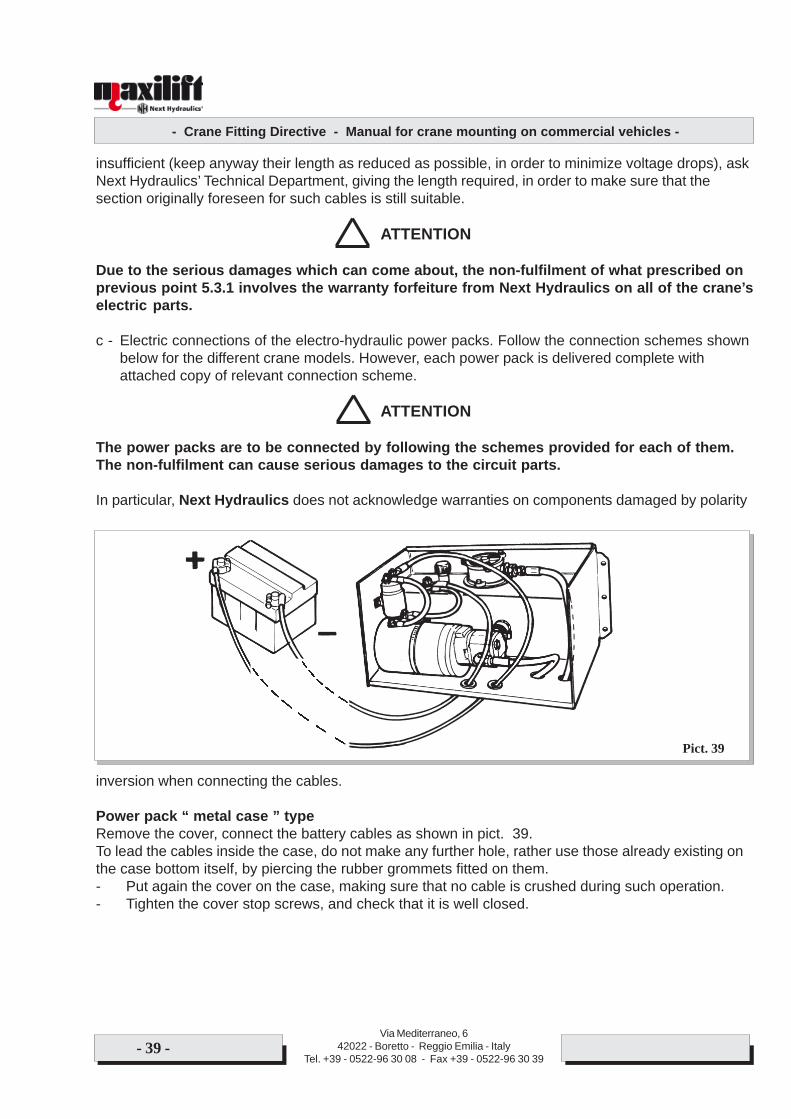
c - Electric connections of the electro-hydraulic power packs. Follow the connection schemes shownbelow for the different crane models. However, each power pack is delivered complete withattached copy of relevant connection scheme.
ATTENTION
The power packs are to be connected by following the schemes provided for each of them.The non-fulfilment can cause serious damages to the circuit parts.
In particular, Next Hydraulics does not acknowledge warranties on components damaged by polarity
inversion when connecting the cables.
Power pack “ metal case ” typeRemove the cover, connect the battery cables as shown in pict. 39.To lead the cables inside the case, do not make any further hole, rather use those already existing onthe case bottom itself, by piercing the rubber grommets fitted on them.- Put again the cover on the case, making sure that no cable is crushed during such operation.- Tighten the cover stop screws, and check that it is well closed.
Pict. 39
- Crane Fitting Directive - Manual for crane mounting on commercial vehicles -
Via Mediterraneo, 642022 - Boretto - Reggio Emilia - Italy
Tel. +39 - 0522-96 30 08 - Fax +39 - 0522-96 30 39- 40 -
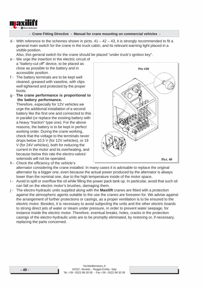
d - With reference to the schemes shown in picts. 41 – 42 – 43, it is strongly recommended to fit ageneral main switch for the crane in the truck cabin, and its relevant warning light placed in avisible position.Also, this general switch for the crane should be placed “under truck’s ignition key”.
e - We urge the insertion in the electric circuit ofa “battery-cut off” device, to be placed asclose as possible to the battery and inaccessible position.
f - The battery terminals are to be kept wellcleaned, greased with vaseline, with clipswell tightened and protected by the properboots.
g - The crane performance is proportional tothe battery performance.
Therefore, especially for 12V vehicles weurge the additional installation of a secondbattery like the first one and connected to thisin parallel (or replace the existing battery witha heavy “traction” type one). For the abovereasons, the battery is to be kept in perfectworking order. During the crane working,check that the voltage to the terminals neverdrops below 10,5 V (for 12V vehicles), or 19V (for 24V vehicles), both for reducing thecurrent in the motor and its overheating, andbecause below this rate the electro-valves’solenoids will not be operated.
h - Check the efficiency of the vehicle’salternator considering the crane installed. In many cases it is advisable to replace the originalalternator by a bigger one, even because the actual power produced by the alternator is alwayslower than the nominal one, due to the high temperature inside of the motor space.
i - Avoid to spill or overflow the oil while filling the power pack tank up. In particular, avoid that such oilcan fall on the electric motor’s brushes, damaging them.
j - The electro-hydraulic units supplied along with the Maxilift cranes are fitted with a protectionagainst the atmospheric agents suitable to the use the cranes are foreseen for. We advise againstthe arrangement of further protections or casings, as a proper ventilation is to be ensured to theelectric motor. Besides, it is necessary to avoid subjecting the units and the other electric boardsto strong direct jets of water or steam under pressure, in order to prevent water seepage, forinstance inside the electric motor. Therefore, eventual breaks, holes, cracks in the protectioncasings of the electro-hydraulic units are to be promptly eliminated, by restoring or, if necessary,replacing the parts concerned.
Pict. 40
Pin #30
- Crane Fitting Directive - Manual for crane mounting on commercial vehicles -
Via Mediterraneo, 642022 - Boretto - Reggio Emilia - Italy
Tel. +39 - 0522-96 30 08 - Fax +39 - 0522-96 30 39- 41 -
ATTENTION
Water seepage inside the motors are obviously due to oversights in following what abovedescribed, therefore Next Hydraulics does not acknowledge any warranty on electric motorsdamaged because of seepage.
Pict. 41
Warning light
Ignitionswitch
Fuse 8A
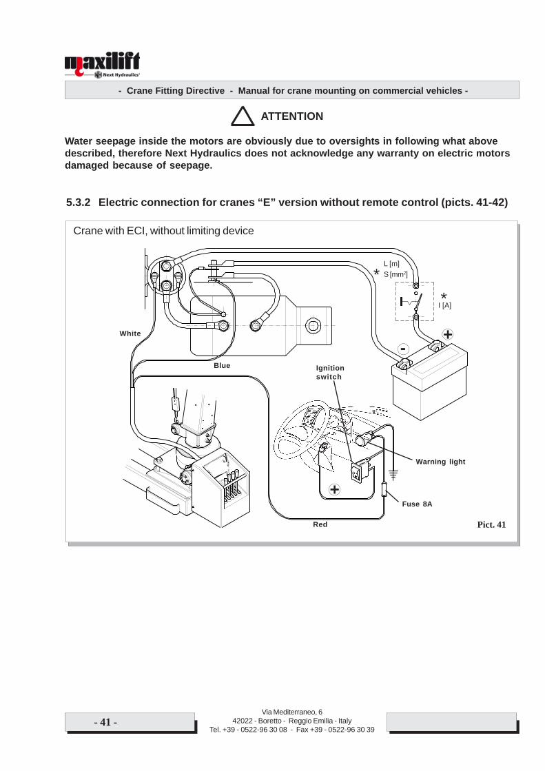
5.3.2 Electric connection for cranes “E” version without remote control (picts. 41-42)
-+
+
Red
Crane with ECI, without limiting device
Blue
White
S [mm2]L [m]
*
I [A]*
- Crane Fitting Directive - Manual for crane mounting on commercial vehicles -
Via Mediterraneo, 642022 - Boretto - Reggio Emilia - Italy
Tel. +39 - 0522-96 30 08 - Fax +39 - 0522-96 30 39- 42 -
Pict. 42
Fuse 8A
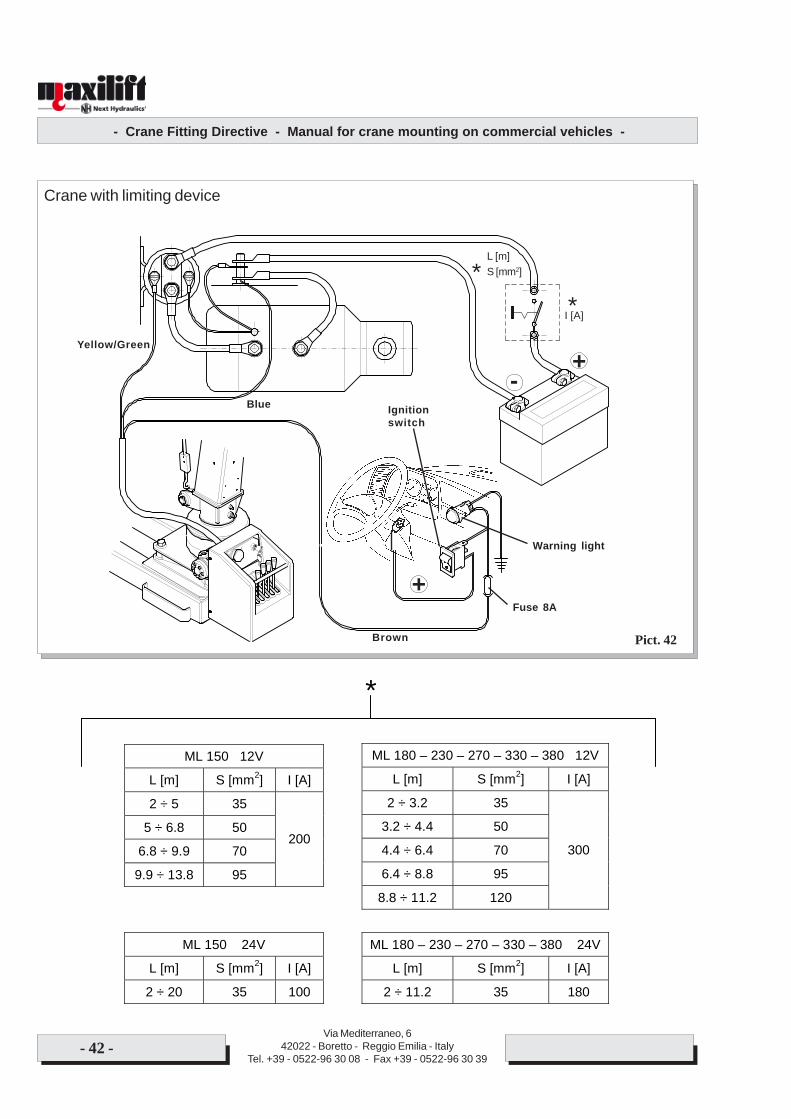
Crane with limiting device
Warning light
+
Ignitionswitch
-
Brown
Blue
Yellow/Green
+
S [mm2]L [m]
*I [A]*
ML 150 12V
L [m] S [mm2] I [A]
2 ÷ 5 35
5 ÷ 6.8 50
6.8 ÷ 9.9 70
9.9 ÷ 13.8 95
200
ML 180 – 230 – 270 – 330 – 380 12V
L [m] S [mm2] I [A]
2 ÷ 3.2 35
3.2 ÷ 4.4 50
4.4 ÷ 6.4 70
6.4 ÷ 8.8 95
8.8 ÷ 11.2 120
300
ML 150 24V
L [m] S [mm2] I [A]
2 ÷ 20 35 100
ML 180 – 230 – 270 – 330 – 380 24V
L [m] S [mm2] I [A]
2 ÷ 11.2 35 180
*
- Crane Fitting Directive - Manual for crane mounting on commercial vehicles -
Via Mediterraneo, 642022 - Boretto - Reggio Emilia - Italy
Tel. +39 - 0522-96 30 08 - Fax +39 - 0522-96 30 39- 43 -
Pict. 43
Fuse 8A
Warning light
+
Ignitionswitch
-
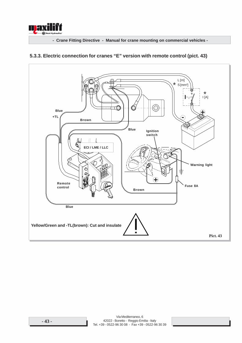
Brown
Blue
+
Blue
Remotecontrol
Blue
+TLBrown
Yellow/Green and -TL(brown): Cut and insulate
5.3.3. Electric connection for cranes “E” version with remote control (pict. 43)
ECI / LME / LLC
S [mm2]L [m]
*I [A]*
- Crane Fitting Directive - Manual for crane mounting on commercial vehicles -
Via Mediterraneo, 642022 - Boretto - Reggio Emilia - Italy
Tel. +39 - 0522-96 30 08 - Fax +39 - 0522-96 30 39- 44 -
5.4 CONNECTION OF CRANE’S HYDRAULIC SYSTEMThe crane’s good working is ensured only if the sizing and the installation of its hydraulic system arecorrectly carried out.
5.4.1 Hydraulic oilThe Maxilift crane is delivered with cylinders and piping filled up with oil and plugged. We employ hydraulicoil ISO 46 grade, with additives against emulsion and wear and tear, suitable for use in temperate climates.After the work, fill up the system through the proper plug on the tank, adding only fresh hydraulic oil, ofgood rate and same grade.
ATTENTION
Look up the lubricants table on the crane’s use and maintenance manual.In case of special requirements or applications consult Next Hydraulics.
5.4.2 Carrying out of the hydraulic system
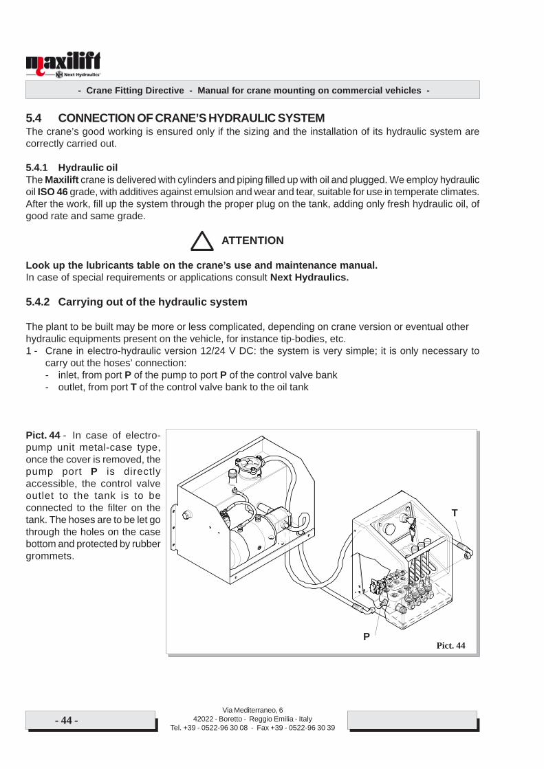
The plant to be built may be more or less complicated, depending on crane version or eventual otherhydraulic equipments present on the vehicle, for instance tip-bodies, etc.1 - Crane in electro-hydraulic version 12/24 V DC: the system is very simple; it is only necessary to
carry out the hoses’ connection:- inlet, from port P of the pump to port P of the control valve bank- outlet, from port T of the control valve bank to the oil tank
Pict. 44 - In case of electro-pump unit metal-case type,once the cover is removed, thepump port P is directlyaccessible, the control valveoutlet to the tank is to beconnected to the filter on thetank. The hoses are to be let gothrough the holes on the casebottom and protected by rubbergrommets.
Pict. 44P
T
- Crane Fitting Directive - Manual for crane mounting on commercial vehicles -
Via Mediterraneo, 642022 - Boretto - Reggio Emilia - Italy
Tel. +39 - 0522-96 30 08 - Fax +39 - 0522-96 30 39- 45 -
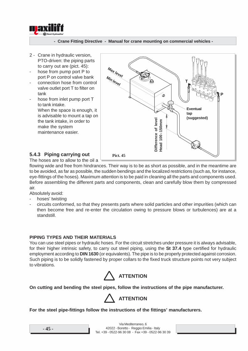
2 - Crane in hydraulic version,PTO-driven: the piping partsto carry out are (pict. 45):
- hose from pump port P toport P on control valve bank
- connection hose from controlvalve outlet port T to filter ontank
- hose from inlet pump port Tto tank intake.When the space is enough, itis advisable to mount a tap onthe tank intake, in order tomake the systemmaintenance easier.
5.4.3 Piping carrying outThe hoses are to allow to the oil aflowing wide and free from hindrances. Their way is to be as short as possible, and in the meantime areto be avoided, as far as possible, the sudden bendings and the localized restrictions (such as, for instance,eye-fittings of the hoses). Maximum attention is to be paid in cleaning all the parts and components used.Before assembling the different parts and components, clean and carefully blow them by compressedair.Absolutely avoid:- hoses’ twisting- circuits conformed, so that they presents parts where solid particles and other impurities (which can
then become free and re-enter the circulation owing to pressure blows or turbulences) are at astandstill.
PIPING TYPES AND THEIR MATERIALSYou can use steel pipes or hydraulic hoses. For the circuit stretches under pressure it is always advisable,for their higher intrinsic safety, to carry out steel piping, using the St 37.4 type certified for hydraulicemployment according to DIN 1630 (or equivalents). The pipe is to be properly protected against corrosion.Such piping is to be solidly fastened by proper collars to the fixed truck structure points not very subjectto vibrations.
ATTENTION
On cutting and bending the steel pipes, follow the instructions of the pipe manufacturer.
ATTENTION
For the steel pipe-fittings follow the instructions of the fittings’ manufacturers.
Pict. 45
Eventualtap(suggested)
Max levelMin level
P
T
Diff
eren
ce o
f le
vel
Hea
d 10
0÷15
0mm
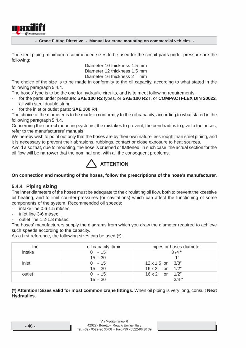
- Crane Fitting Directive - Manual for crane mounting on commercial vehicles -
Via Mediterraneo, 642022 - Boretto - Reggio Emilia - Italy
Tel. +39 - 0522-96 30 08 - Fax +39 - 0522-96 30 39- 46 -
The steel piping minimum recommended sizes to be used for the circuit parts under pressure are thefollowing:
Diameter 10 thickness 1.5 mmDiameter 12 thickness 1.5 mmDiameter 16 thickness 2 mm
The choice of the size is to be made in conformity to the oil capacity, according to what stated in thefollowing paragraph 5.4.4.The hoses’ type is to be the one for hydraulic circuits, and is to meet following requirements:- for the parts under pressure: SAE 100 R2 types, or SAE 100 R2T, or COMPACTFLEX DIN 20022,
all with steel double string- for the inlet or outlet parts: SAE 100 R4.The choice of the diameter is to be made in conformity to the oil capacity, according to what stated in thefollowing paragraph 5.4.4.Concerning the correct mounting systems, the mistakes to prevent, the bend radius to give to the hoses,refer to the manufacturers’ manuals.We hereby wish to point out only that the hoses are by their own nature less rough than steel piping, andit is necessary to prevent their abrasions, rubbings, contact or close exposure to heat sources.Avoid also that, due to mounting, the hose is crushed or flattened: in such case, the actual section for theoil flow will be narrower that the nominal one, with all the consequent problems.
ATTENTION
On connection and mounting of the hoses, follow the prescriptions of the hose’s manufacturer.
5.4.4 Piping sizingThe inner diameters of the hoses must be adequate to the circulating oil flow, both to prevent the xcessiveoil heating, and to limit counter-pressures (or cavitations) which can affect the functioning of somecomponents of the system. Recommended oil speeds:- intake line 0.6-1.5 mt/sec- inlet line 3-6 mt/sec- outlet line 1.2-1.8 mt/sec.The hoses’ manufacturers supply the diagrams from which you draw the diameter required to achievesuch speeds according to the capacity.As a first reference, the following sizes can be used (*):
line oil capacity lt/min pipes or hoses diameterintake 0 - 15 3 /4 “
15 - 30 1”inlet 0 - 15 12 x 1.5 or 3/8”
15 - 30 16 x 2 or 1/2”outlet 0 - 15 16 x 2 or 1/2”
15 - 30 3/4 “
(*) Attention! Sizes valid for most common crane fittings. When oil piping is very long, consult NextHydraulics.
- Crane Fitting Directive - Manual for crane mounting on commercial vehicles -
Via Mediterraneo, 642022 - Boretto - Reggio Emilia - Italy
Tel. +39 - 0522-96 30 08 - Fax +39 - 0522-96 30 39- 47 -
5.4.5 General advice- The oil temperature, after a normal working period, must not exceed 70°C with environmental
temperatures around 20°C. Higher oil temperatures can mean that the hoses’ diameters are insufficient,or that there are localized narrowings. In case of special requirements (very high environmentaltemperatures, very complicated hoses’ way, continuous pump working for long periods), which needfurther adjustments to keep the oil temperature within the foreseen limits, pass to the immediatelyhigher hose diameter. It could be necessary to install an oil tank with bigger capacity. Consult NextHydraulics.
- When you expect to use the crane very often with temperatures below –5/-10°C, replace the oil byone with proper ISO grade. Consult Next Hydraulics about this, in order to make sure of its compatibilitywith the seals. It could be necessary to apply to the tank a heater with electric resistance, in order tolead the oil to a sufficient temperature before the operations’ starting. This heater is to be disconnectedas soon as the purpose is achieved. Provide proper devices and instructions to avoid that the user letit plugged in more than necessary.
- Oil tank position: even with minimum oil level, the intake pump port must always be minimum 100-150 mm below this level; its position must allow the easy level checking and maintenance (topping upand filter replacement on the outlet line, if present).
- Keep the intake piping as short and straight as possible. We advise against the installation of a filteron such line.
- The counter-pressure on the outlet line, gauged by applying a T–shaped fitting on the port T of thehydraulic control valve must not exceed 15 bar. If required, modify the line to re-enter within such limit.
DANGER
The non-fulfilment of the prescribed precautions for the different hoses’ lines involves cranebad functioning and damaging of the circuit components.
- When the installation is finished, check the arrangement and the way of the hoses in all of the crane’sconditions and working positions. In particular, the hoses lying within 1 meter from the user’s positionare to be properly shielded, in order to protect him from pressure oil leaks.
!
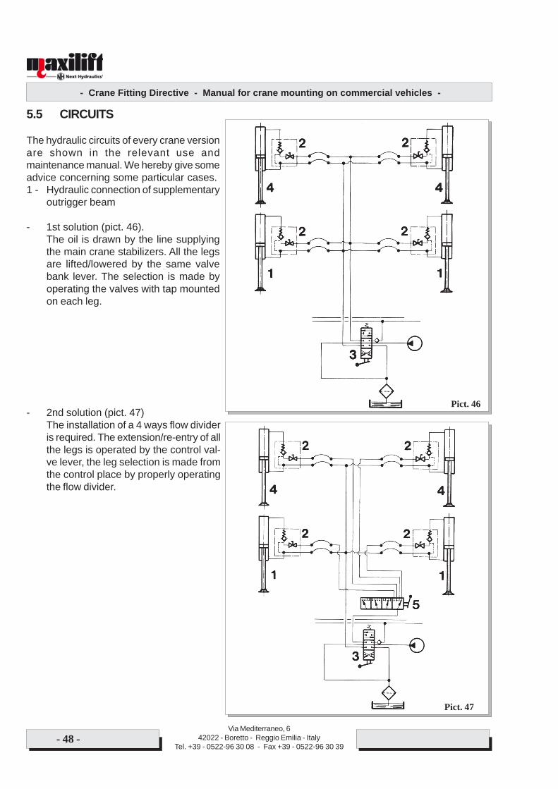
- Crane Fitting Directive - Manual for crane mounting on commercial vehicles -
Via Mediterraneo, 642022 - Boretto - Reggio Emilia - Italy
Tel. +39 - 0522-96 30 08 - Fax +39 - 0522-96 30 39- 48 -
5.5 CIRCUITS
The hydraulic circuits of every crane versionare shown in the relevant use andmaintenance manual. We hereby give someadvice concerning some particular cases.1 - Hydraulic connection of supplementary
outrigger beam
- 1st solution (pict. 46).The oil is drawn by the line supplyingthe main crane stabilizers. All the legsare lifted/lowered by the same valvebank lever. The selection is made byoperating the valves with tap mountedon each leg.
- 2nd solution (pict. 47)The installation of a 4 ways flow divideris required. The extension/re-entry of allthe legs is operated by the control val-ve lever, the leg selection is made fromthe control place by properly operatingthe flow divider.
Pict. 47
Pict. 46
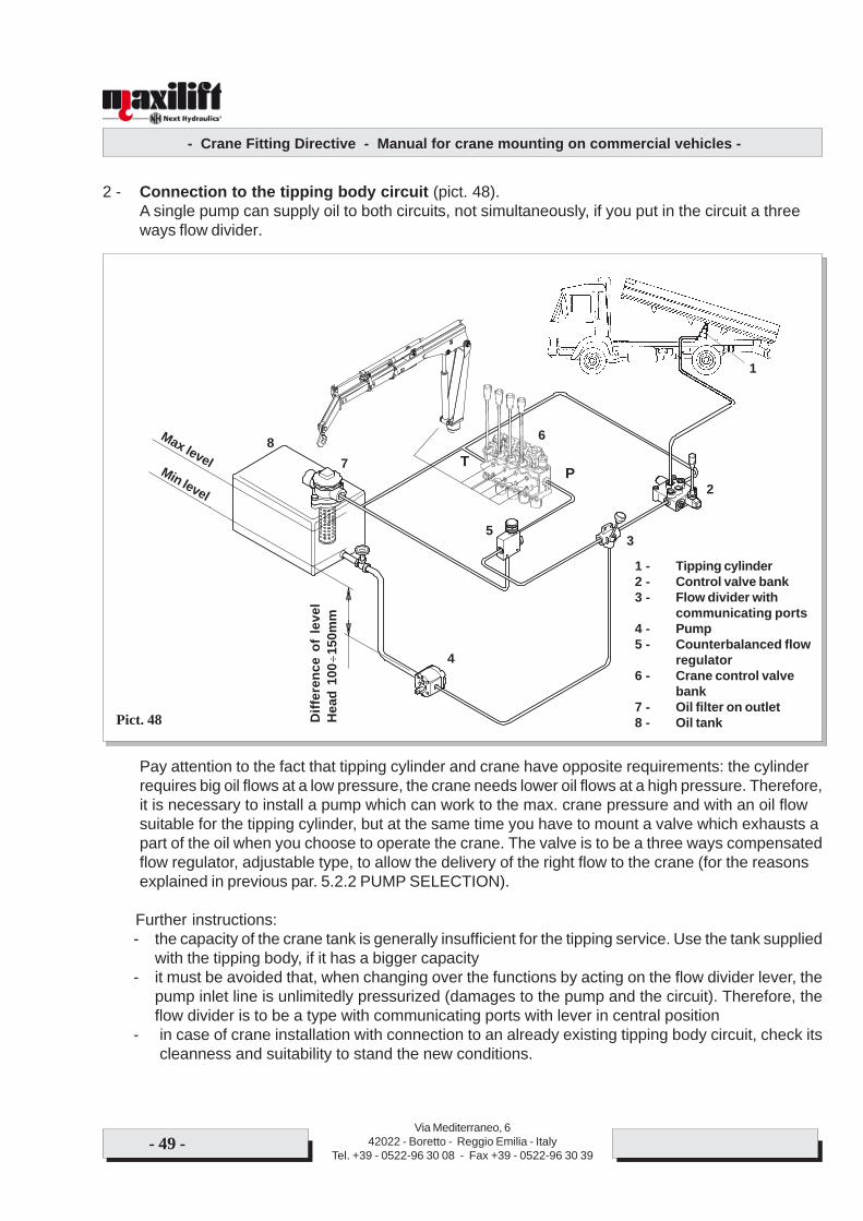
- Crane Fitting Directive - Manual for crane mounting on commercial vehicles -
Via Mediterraneo, 642022 - Boretto - Reggio Emilia - Italy
Tel. +39 - 0522-96 30 08 - Fax +39 - 0522-96 30 39- 49 -
2 - Connection to the tipping body circuit (pict. 48).A single pump can supply oil to both circuits, not simultaneously, if you put in the circuit a threeways flow divider.
Pay attention to the fact that tipping cylinder and crane have opposite requirements: the cylinderrequires big oil flows at a low pressure, the crane needs lower oil flows at a high pressure. Therefore,it is necessary to install a pump which can work to the max. crane pressure and with an oil flowsuitable for the tipping cylinder, but at the same time you have to mount a valve which exhausts apart of the oil when you choose to operate the crane. The valve is to be a three ways compensatedflow regulator, adjustable type, to allow the delivery of the right flow to the crane (for the reasonsexplained in previous par. 5.2.2 PUMP SELECTION).
Further instructions:- the capacity of the crane tank is generally insufficient for the tipping service. Use the tank supplied
with the tipping body, if it has a bigger capacity- it must be avoided that, when changing over the functions by acting on the flow divider lever, the
pump inlet line is unlimitedly pressurized (damages to the pump and the circuit). Therefore, theflow divider is to be a type with communicating ports with lever in central position
- in case of crane installation with connection to an already existing tipping body circuit, check itscleanness and suitability to stand the new conditions.
Pict. 48 Diff
eren
ce o
f le
vel
Hea
d 10
0÷15
0mm
Max levelMin levelP
T
1
2
3
4
5
6
78
1 - Tipping cylinder2 - Control valve bank3 - Flow divider with
communicating ports4 - Pump5 - Counterbalanced flow
regulator6 - Crane control valve
bank7 - Oil filter on outlet8 - Oil tank
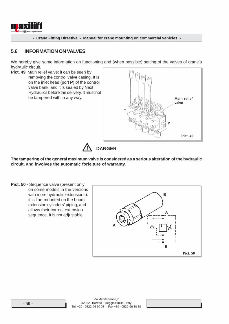
- Crane Fitting Directive - Manual for crane mounting on commercial vehicles -
Via Mediterraneo, 642022 - Boretto - Reggio Emilia - Italy
Tel. +39 - 0522-96 30 08 - Fax +39 - 0522-96 30 39- 50 -
5.6 INFORMATION ON VALVES
We hereby give some information on functioning and (when possible) setting of the valves of crane’shydraulic circuit.Pict. 49 Main relief valve: it can be seen by
removing the control valve casing. It ison the inlet head (port P) of the controlvalve bank, and it is sealed by NextHydraulics before the delivery. It must notbe tampered with in any way.
DANGER
The tampering of the general maximum valve is considered as a serious alteration of the hydrauliccircuit, and involves the automatic forfeiture of warranty.
Pict. 50 - Sequence valve (present onlyon some models in the versionswith more hydraulic extensions):it is line-mounted on the boomextension cylinders’ piping, andallows their correct extensionsequence. It is not adjustable.
Pict. 49
Main reliefvalve
P
T
Pict. 50
B
A
A
B
!
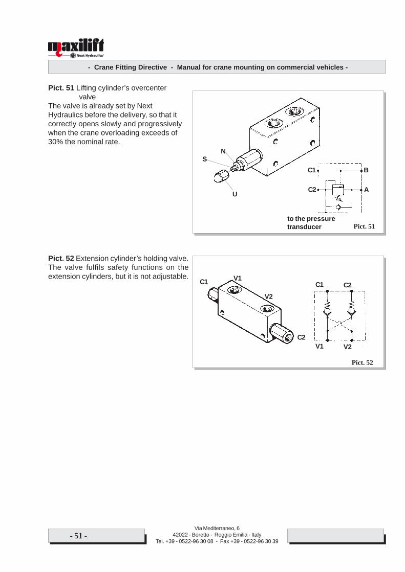
- Crane Fitting Directive - Manual for crane mounting on commercial vehicles -
Via Mediterraneo, 642022 - Boretto - Reggio Emilia - Italy
Tel. +39 - 0522-96 30 08 - Fax +39 - 0522-96 30 39- 51 -
Pict. 51 Lifting cylinder’s overcentervalve
The valve is already set by NextHydraulics before the delivery, so that itcorrectly opens slowly and progressivelywhen the crane overloading exceeds of30% the nominal rate.
Pict. 52 Extension cylinder’s holding valve.The valve fulfils safety functions on theextension cylinders, but it is not adjustable.
Pict. 51
NS
U A
B
C2
C1
to the pressuretransducer
Pict. 52
C1 C2
V1 V2
V2
V1C1
C2
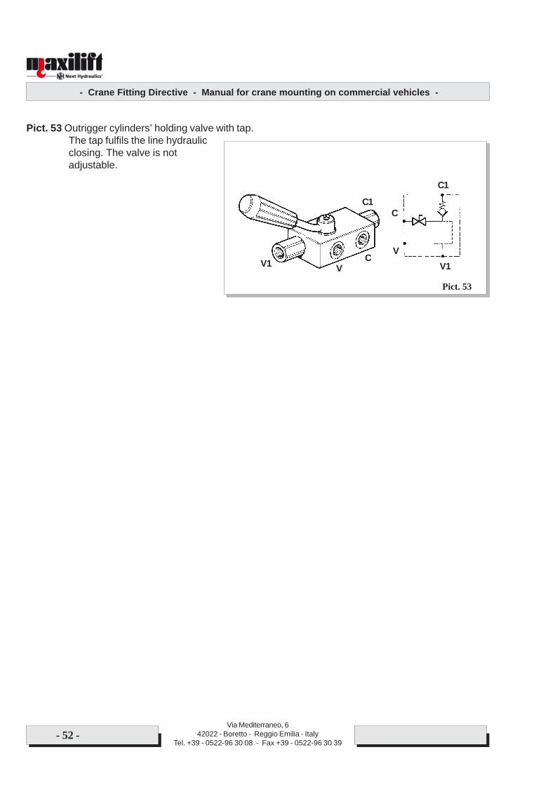
- Crane Fitting Directive - Manual for crane mounting on commercial vehicles -
Via Mediterraneo, 642022 - Boretto - Reggio Emilia - Italy
Tel. +39 - 0522-96 30 08 - Fax +39 - 0522-96 30 39- 52 -
Pict. 53 Outrigger cylinders’ holding valve with tap.The tap fulfils the line hydraulicclosing. The valve is notadjustable.
Pict. 53
C1
C
VV1
C1
V1 VC
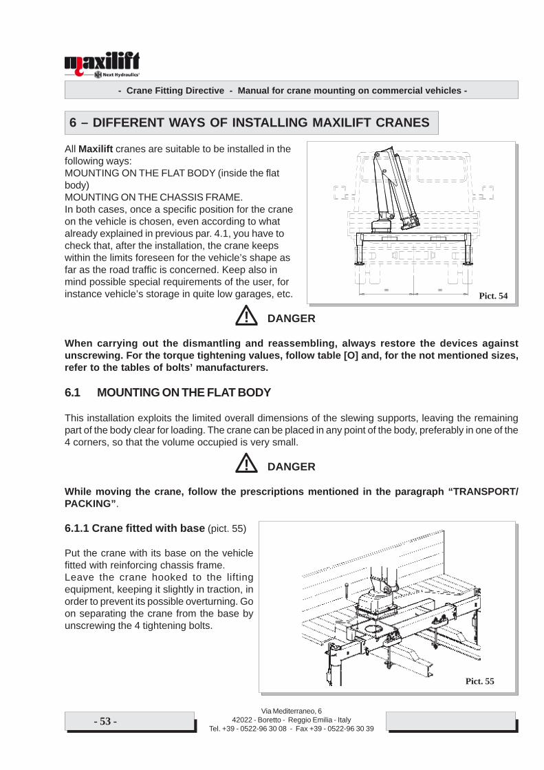
- Crane Fitting Directive - Manual for crane mounting on commercial vehicles -
Via Mediterraneo, 642022 - Boretto - Reggio Emilia - Italy
Tel. +39 - 0522-96 30 08 - Fax +39 - 0522-96 30 39- 53 -
6 – DIFFERENT WAYS OF INSTALLING MAXILIFT CRANES
All Maxilift cranes are suitable to be installed in thefollowing ways:MOUNTING ON THE FLAT BODY (inside the flatbody)MOUNTING ON THE CHASSIS FRAME.In both cases, once a specific position for the craneon the vehicle is chosen, even according to whatalready explained in previous par. 4.1, you have tocheck that, after the installation, the crane keepswithin the limits foreseen for the vehicle’s shape asfar as the road traffic is concerned. Keep also inmind possible special requirements of the user, forinstance vehicle’s storage in quite low garages, etc.
DANGER
When carrying out the dismantling and reassembling, always restore the devices againstunscrewing. For the torque tightening values, follow table [O] and, for the not mentioned sizes,refer to the tables of bolts’ manufacturers.
6.1 MOUNTING ON THE FLAT BODY
This installation exploits the limited overall dimensions of the slewing supports, leaving the remainingpart of the body clear for loading. The crane can be placed in any point of the body, preferably in one of the4 corners, so that the volume occupied is very small.
DANGER
While moving the crane, follow the prescriptions mentioned in the paragraph “TRANSPORT/PACKING”.
6.1.1 Crane fitted with base (pict. 55)
Put the crane with its base on the vehiclefitted with reinforcing chassis frame.Leave the crane hooked to the liftingequipment, keeping it slightly in traction, inorder to prevent its possible overturning. Goon separating the crane from the base byunscrewing the 4 tightening bolts.
!
!
Pict. 55
Pict. 54
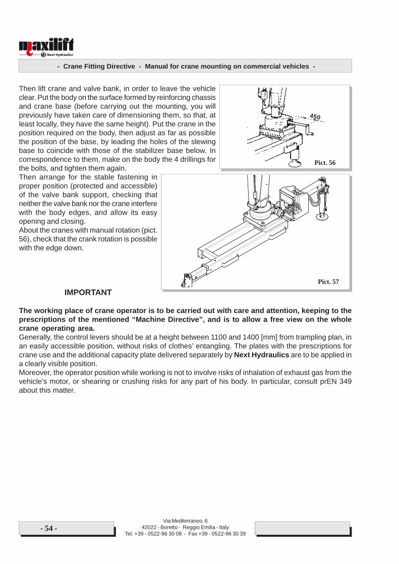
- Crane Fitting Directive - Manual for crane mounting on commercial vehicles -
Via Mediterraneo, 642022 - Boretto - Reggio Emilia - Italy
Tel. +39 - 0522-96 30 08 - Fax +39 - 0522-96 30 39- 54 -
Then lift crane and valve bank, in order to leave the vehicleclear. Put the body on the surface formed by reinforcing chassisand crane base (before carrying out the mounting, you willpreviously have taken care of dimensioning them, so that, atleast locally, they have the same height). Put the crane in theposition required on the body, then adjust as far as possiblethe position of the base, by leading the holes of the slewingbase to coincide with those of the stabilizer base below. Incorrespondence to them, make on the body the 4 drillings forthe bolts, and tighten them again.Then arrange for the stable fastening inproper position (protected and accessible)of the valve bank support, checking thatneither the valve bank nor the crane interferewith the body edges, and allow its easyopening and closing.About the cranes with manual rotation (pict.56), check that the crank rotation is possiblewith the edge down.
IMPORTANT
The working place of crane operator is to be carried out with care and attention, keeping to theprescriptions of the mentioned “Machine Directive”, and is to allow a free view on the wholecrane operating area.Generally, the control levers should be at a height between 1100 and 1400 [mm] from trampling plan, inan easily accessible position, without risks of clothes’ entangling. The plates with the prescriptions forcrane use and the additional capacity plate delivered separately by Next Hydraulics are to be applied ina clearly visible position.Moreover, the operator position while working is not to involve risks of inhalation of exhaust gas from thevehicle’s motor, or shearing or crushing risks for any part of his body. In particular, consult prEN 349about this matter.
Pict. 57
Pict. 56
450

- Crane Fitting Directive - Manual for crane mounting on commercial vehicles -
Via Mediterraneo, 642022 - Boretto - Reggio Emilia - Italy
Tel. +39 - 0522-96 30 08 - Fax +39 - 0522-96 30 39- 55 -
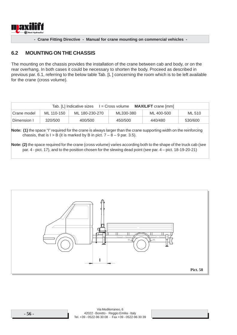
- Crane Fitting Directive - Manual for crane mounting on commercial vehicles -
Via Mediterraneo, 642022 - Boretto - Reggio Emilia - Italy
Tel. +39 - 0522-96 30 08 - Fax +39 - 0522-96 30 39- 56 -
6.2 MOUNTING ON THE CHASSIS
The mounting on the chassis provides the installation of the crane between cab and body, or on therear overhang. In both cases it could be necessary to shorten the body. Proceed as described inprevious par. 6.1, referring to the below table Tab. [L ] concerning the room which is to be left availablefor the crane (cross volume).
Tab. [L] Indicative sizes I = Cross volume MAXILIFT crane [mm]
Crane model ML 110-150 ML 180-230-270 ML330-380 ML 400-500 ML 510
Dimension I 320/500 400/500 450/500 440/480 530/600
Note: (1) the space “I” required for the crane is always larger than the crane supporting width on the reinforcingchassis, that is I > B (it is marked by B in pict. 7 – 8 – 9 par. 3.5).
Note: (2) the space required for the crane (cross volume) varies according both to the shape of the truck cab (seepar. 4 - pict. 17), and to the position chosen for the slewing dead point (see par. 4 – pict. 18-19-20-21)
Pict. 58
I
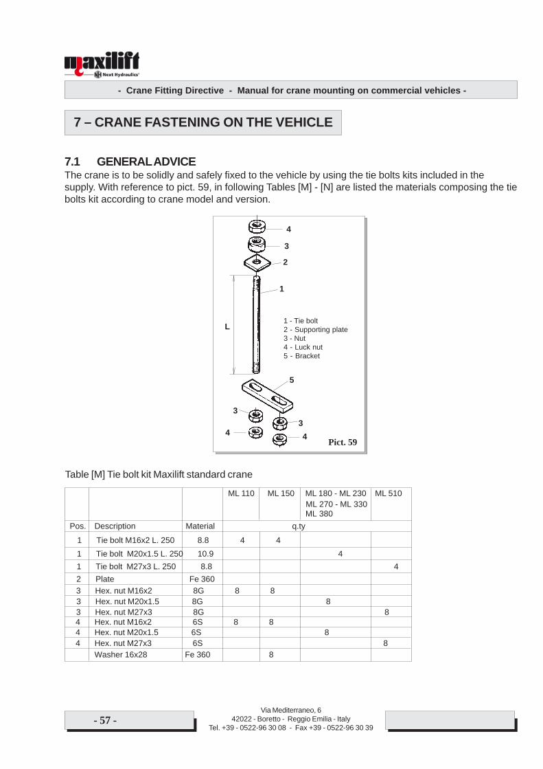
- Crane Fitting Directive - Manual for crane mounting on commercial vehicles -
Via Mediterraneo, 642022 - Boretto - Reggio Emilia - Italy
Tel. +39 - 0522-96 30 08 - Fax +39 - 0522-96 30 39- 57 -
7 – CRANE FASTENING ON THE VEHICLE
7.1 GENERAL ADVICEThe crane is to be solidly and safely fixed to the vehicle by using the tie bolts kits included in thesupply. With reference to pict. 59, in following Tables [M] - [N] are listed the materials composing the tiebolts kit according to crane model and version.
Pict. 59
3
1
2
3
4
5
34
L1 - Tie bolt2 - Supporting plate3 - Nut4 - Luck nut5 - Bracket
ML 110 ML 150 ML 180 - ML 230 ML 510ML 270 - ML 330ML 380
Pos. Description Material q.ty
1 Tie bolt M16x2 L. 250 8.8 4 41 Tie bolt M20x1.5 L. 250 10.9 41 Tie bolt M27x3 L. 250 8.8 42 Plate Fe 3603 Hex. nut M16x2 8G 8 83 Hex. nut M20x1.5 8G 83 Hex. nut M27x3 8G 84 Hex. nut M16x2 6S 8 84 Hex. nut M20x1.5 6S 84 Hex. nut M27x3 6S 8 Washer 16x28 Fe 360 8
4
Table [M] Tie bolt kit Maxilift standard crane
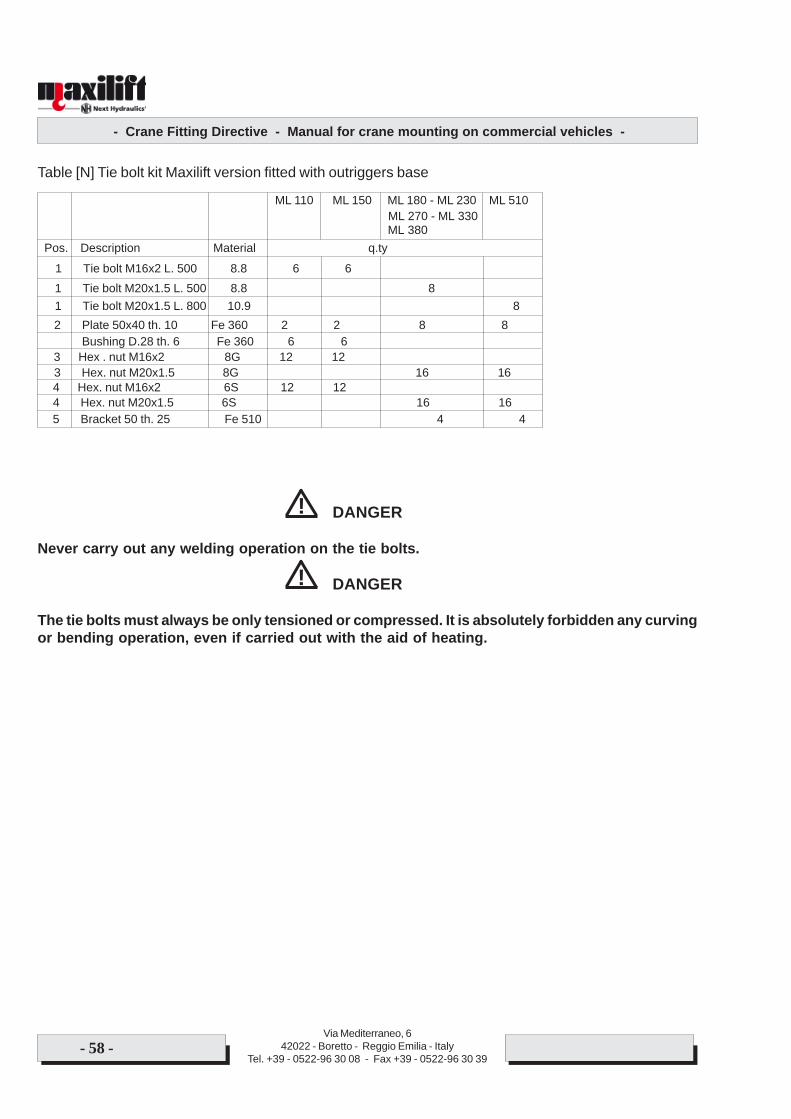
- Crane Fitting Directive - Manual for crane mounting on commercial vehicles -
Via Mediterraneo, 642022 - Boretto - Reggio Emilia - Italy
Tel. +39 - 0522-96 30 08 - Fax +39 - 0522-96 30 39- 58 -
DANGER
Never carry out any welding operation on the tie bolts.
DANGER
The tie bolts must always be only tensioned or compressed. It is absolutely forbidden any curvingor bending operation, even if carried out with the aid of heating.
!
!
ML 110 ML 150 ML 180 - ML 230 ML 510ML 270 - ML 330ML 380
Pos. Description Material q.ty
1 Tie bolt M16x2 L. 500 8.8 6 61 Tie bolt M20x1.5 L. 500 8.8 8
Bushing D.28 th. 6 Fe 360 6 63 Hex . nut M16x2 8G 12 123 Hex. nut M20x1.5 8G 16 164 Hex. nut M16x2 6S 12 124 Hex. nut M20x1.5 6S 16 165 Bracket 50 th. 25 Fe 510 4 4
Table [N] Tie bolt kit Maxilift version fitted with outriggers base
2 Plate 50x40 th. 10 Fe 360 2 2 8 81 Tie bolt M20x1.5 L. 800 10.9 8
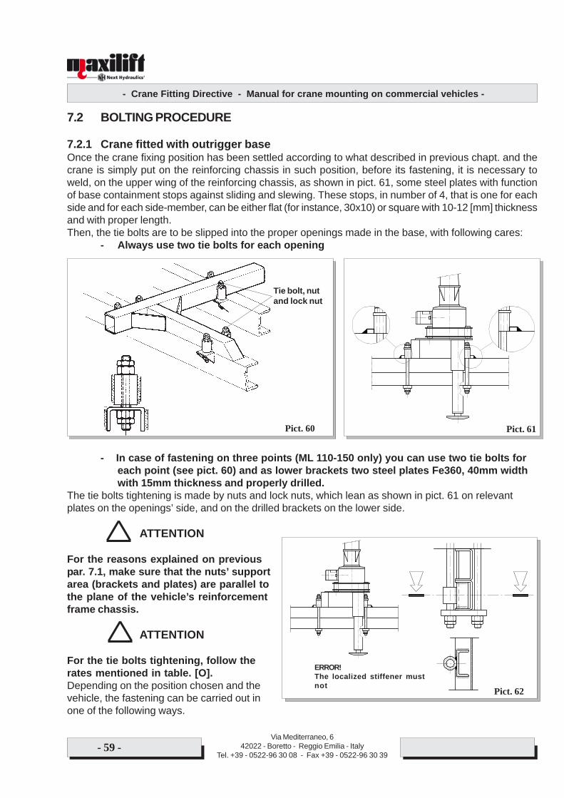
- Crane Fitting Directive - Manual for crane mounting on commercial vehicles -
Via Mediterraneo, 642022 - Boretto - Reggio Emilia - Italy
Tel. +39 - 0522-96 30 08 - Fax +39 - 0522-96 30 39- 59 -
7.2 BOLTING PROCEDURE
7.2.1 Crane fitted with outrigger baseOnce the crane fixing position has been settled according to what described in previous chapt. and thecrane is simply put on the reinforcing chassis in such position, before its fastening, it is necessary toweld, on the upper wing of the reinforcing chassis, as shown in pict. 61, some steel plates with functionof base containment stops against sliding and slewing. These stops, in number of 4, that is one for eachside and for each side-member, can be either flat (for instance, 30x10) or square with 10-12 [mm] thicknessand with proper length.Then, the tie bolts are to be slipped into the proper openings made in the base, with following cares:
- Always use two tie bolts for each opening
- In case of fastening on three points (ML 110-150 only) you can use two tie bolts foreach point (see pict. 60) and as lower brackets two steel plates Fe360, 40mm widthwith 15mm thickness and properly drilled.
The tie bolts tightening is made by nuts and lock nuts, which lean as shown in pict. 61 on relevantplates on the openings’ side, and on the drilled brackets on the lower side.
ATTENTION
For the reasons explained on previouspar. 7.1, make sure that the nuts’ supportarea (brackets and plates) are parallel tothe plane of the vehicle’s reinforcementframe chassis.
ATTENTION
For the tie bolts tightening, follow therates mentioned in table. [O].Depending on the position chosen and thevehicle, the fastening can be carried out inone of the following ways.
Pict. 61Pict. 60
Tie bolt, nutand lock nut
Pict. 62
ERROR!The localized stiffener mustnot
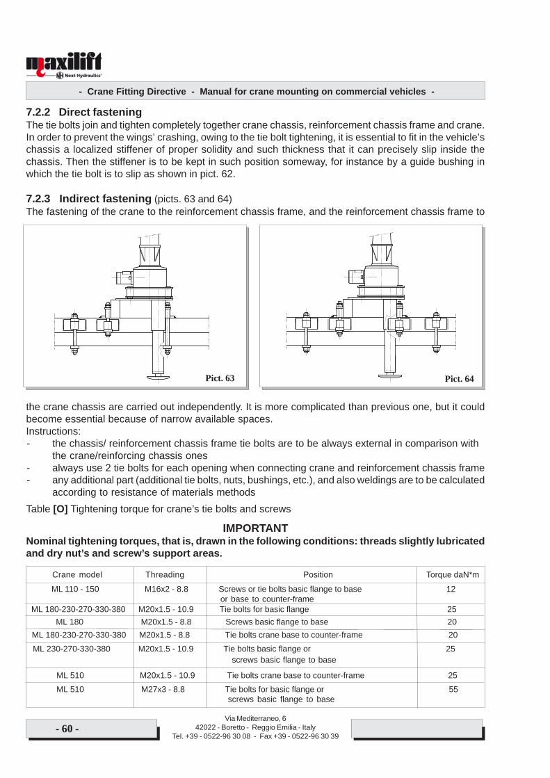
- Crane Fitting Directive - Manual for crane mounting on commercial vehicles -
Via Mediterraneo, 642022 - Boretto - Reggio Emilia - Italy
Tel. +39 - 0522-96 30 08 - Fax +39 - 0522-96 30 39- 60 -
7.2.2 Direct fasteningThe tie bolts join and tighten completely together crane chassis, reinforcement chassis frame and crane.In order to prevent the wings’ crashing, owing to the tie bolt tightening, it is essential to fit in the vehicle’schassis a localized stiffener of proper solidity and such thickness that it can precisely slip inside thechassis. Then the stiffener is to be kept in such position someway, for instance by a guide bushing inwhich the tie bolt is to slip as shown in pict. 62.
7.2.3 Indirect fastening (picts. 63 and 64)The fastening of the crane to the reinforcement chassis frame, and the reinforcement chassis frame to
the crane chassis are carried out independently. It is more complicated than previous one, but it couldbecome essential because of narrow available spaces.Instructions:- the chassis/ reinforcement chassis frame tie bolts are to be always external in comparison with
the crane/reinforcing chassis ones- always use 2 tie bolts for each opening when connecting crane and reinforcement chassis frame- any additional part (additional tie bolts, nuts, bushings, etc.), and also weldings are to be calculated
according to resistance of materials methodsTable [O] Tightening torque for crane’s tie bolts and screws
IMPORTANTNominal tightening torques, that is, drawn in the following conditions: threads slightly lubricatedand dry nut’s and screw’s support areas.
Pict. 63 Pict. 64
Crane model Threading Position Torque daN*m
ML 110 - 150 M16x2 - 8.8 Screws or tie bolts basic flange to base 12
ML 180 M20x1.5 - 8.8 Screws basic flange to base 20
or base to counter-frame
ML 230-270-330-380 M20x1.5 - 10.9 Tie bolts basic flange or 25
ML 180-230-270-330-380 M20x1.5 - 10.9 Tie bolts for basic flange 25
screws basic flange to base
ML 510 M27x3 - 8.8 Tie bolts for basic flange or 55screws basic flange to base
ML 510 M20x1.5 - 10.9 Tie bolts crane base to counter-frame 25
ML 180-230-270-330-380 M20x1.5 - 8.8 Tie bolts crane base to counter-frame 20
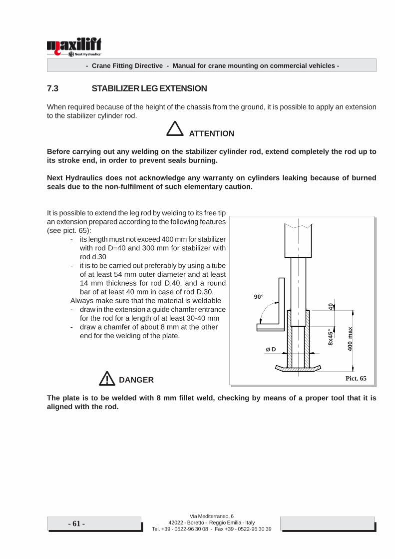
- Crane Fitting Directive - Manual for crane mounting on commercial vehicles -
Via Mediterraneo, 642022 - Boretto - Reggio Emilia - Italy
Tel. +39 - 0522-96 30 08 - Fax +39 - 0522-96 30 39- 61 -
7.3 STABILIZER LEG EXTENSION
When required because of the height of the chassis from the ground, it is possible to apply an extensionto the stabilizer cylinder rod.
ATTENTION
Before carrying out any welding on the stabilizer cylinder rod, extend completely the rod up toits stroke end, in order to prevent seals burning.
Next Hydraulics does not acknowledge any warranty on cylinders leaking because of burnedseals due to the non-fulfilment of such elementary caution.
It is possible to extend the leg rod by welding to its free tipan extension prepared according to the following features(see pict. 65):
- its length must not exceed 400 mm for stabilizerwith rod D=40 and 300 mm for stabilizer withrod d.30
- it is to be carried out preferably by using a tubeof at least 54 mm outer diameter and at least14 mm thickness for rod D.40, and a roundbar of at least 40 mm in case of rod D.30.
Always make sure that the material is weldable- draw in the extension a guide chamfer entrance
for the rod for a length of at least 30-40 mm- draw a chamfer of about 8 mm at the other
end for the welding of the plate.
DANGER
The plate is to be welded with 8 mm fillet weld, checking by means of a proper tool that it isaligned with the rod.
! Pict. 65
400
max
Ø D
40
90°
8x45
°

- Crane Fitting Directive - Manual for crane mounting on commercial vehicles -
Via Mediterraneo, 642022 - Boretto - Reggio Emilia - Italy
Tel. +39 - 0522-96 30 08 - Fax +39 - 0522-96 30 39- 62 -
CONTENTS
1 INTRODUCTION ........................................................................................................ Page .. 11.1 Basic information .......................................................................................................... “ ...... 11.2 Machine Directive .......................................................................................................... “ ...... 31.3 Reference norms .......................................................................................................... “ ...... 3
2 MOUNTING PREPARATION ......................................................................................... “ ...... 42.1 Starting preparation ....................................................................................................... “ ...... 42.2 Crane moving and storage ............................................................................................ “ ...... 42.3 Table of crane masses and sizes ................................................................................. “ ...... 52.4 Precautions ................................................................................................................... “ ...... 8
3 CRANE/VEHICLE MESHING...................................................................................... Page .. 93.1 Minimum vehicle ........................................................................................................... “ ...... 93.2 Checking the crane - vehicle meshing .......................................................................... “ .... 103.3 Safety calculation against overturning ........................................................................... “ .....113.4 Dimensioning of reinforcing chassis frame ................................................................... “ .... 143.4.1 Reinforcing chassis calculation .................................................................................... “ .... 143.4.2 Materials for reinforcing chassis ................................................................................... “ .... 153.4.3 Reinforcement chassis calculation ............................................................................... “ .... 153.5 Building a reinforcement chassis .................................................................................. “ .... 163.6 Reinforcing chassis fixing on the vehicle ...................................................................... “ .... 20
4 CRANE FASTENING ON THE VEHICLE ...................................................................... “ .... 224.1 General instructions ...................................................................................................... “ .... 224.2 Changing the dead point position .................................................................................. “ .... 244.2.1 Worm gear operated cranes ......................................................................................... “ .... 244.2.2 Rack and pinion models ................................................................................................ “ .... 274.3 Checks and verifications ............................................................................................... “ .... 27
5 CRANE CONNECTION ............................................................................................. Page 305.1 General information ....................................................................................................... “ .... 305.2 Crane’s power supply ................................................................................................... “ .... 315.2.1 Crane with working cycle not limited to short period ..................................................... “ .... 315.2.2 Selection of the pump and the PTO .............................................................................. “ .... 325.2.3 Installation of pumps and PTO’s ................................................................................... “ .... 335.2.4 Controls of the pump-PTO operation ............................................................................ “ .... 355.2.5 Electric connection for “H” version crane ...................................................................... “ .... 375.3 Crane with working cycle limited to short periods of time ............................................. “ .... 38

- Crane Fitting Directive - Manual for crane mounting on commercial vehicles -
Via Mediterraneo, 642022 - Boretto - Reggio Emilia - Italy
Tel. +39 - 0522-96 30 08 - Fax +39 - 0522-96 30 39- 63 -
5.3.1 General advice .............................................................................................................. “ .... 385.3.2 Electric connection for “E” version crane without remote conrol .................................. “ .... 415.3.3 Electric connection for “E version crane with remote control ........................................ “ .... 435.4 Connection of crane’s hydraulic system ....................................................................... “ .... 445.4.1 Hydraulic oil ................................................................................................................... “ .... 445.4.2 Carrying out of the hydraulic system ............................................................................. “ .... 445.4.3 Piping carrying out......................................................................................................... “ .... 455.4.4 Piping sizing .................................................................................................................. “ .... 465.4.5 General advice .............................................................................................................. “ .... 475.5 Circuits .......................................................................................................................... “ .... 485.6 Information on valves .................................................................................................... “ .... 50
6 DIFFERENT WAYS OF INSTALLING MAXILIFT CRANE ......................................... Page .. 536.1 Mounting on the flat body .............................................................................................. “ ...... 536.1.1 Crane fitted with base .................................................................................................. “ ...... 536.1.2 Crane without base (= standard crane) ....................................................................... “ ...... 546.2 Mounting on the chassis .............................................................................................. “ ...... 56
7 CRANE FASTENING ON THE VEHICLE ................................................................. Page .. 577.1 General advice ............................................................................................................. “ ...... 577.2 Bolting procedure ......................................................................................................... “ ...... 597.2.1 Crane fitted with outrigger base ................................................................................... “ ...... 597.2.2 Direct fastening ............................................................................................................ “ ...... 607.2.3 Indirect fastening .......................................................................................................... “ ...... 607.3 Welding of the stabilizer leg extension ......................................................................... “ ... ..61

Via Mediterraneo, 642022 - Boretto - Reggio Emilia - Italy
Tel. +39 - 0522-96 30 08 - Fax +39 - 0522-96 30 39- 64 -

Via Mediterraneo, 642022 - Boretto - Reggio Emilia - Italy
Tel. +39 - 0522-96 30 08 - Fax +39 - 0522-96 30 39- 64 -

NEXT HYDRAULICS S.r.l.Via Mediterraneo, 6 Boretto (RE) - ITALY
Tel. +39 - 0522-963008 Fax +39 - 0522-963039e-mail: [email protected]
COPYRIGHT BY NEXT HYDRAULICS s.r.l.Reproduction and distribution are forbidden according to lawwithout written permission in writing from Next Hydraulics s.r.l.
www.nexthydraulics.com