Embed Size (px)
DESCRIPTION
Jointer manual
Citation preview
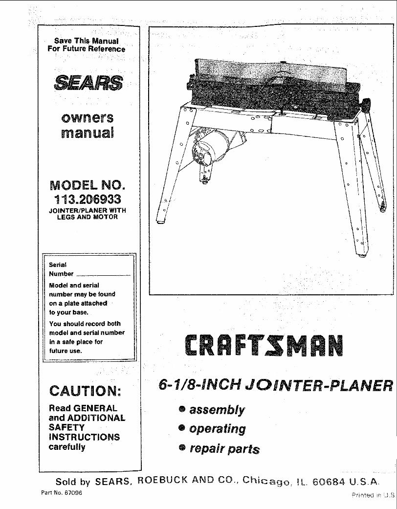
Save This ManualFor Future Reference
SEARS
MODEL NO.1 "l3.206933
JOINTER/PLANER WITHLEGS AND MOTOR
Serial
Number
Model and serial
number may be found
on a plate attachedto your base,
You should record both
model and serial number
in a safe place forfuture use.
CAUTION:Read GENERALand ADDITIONALSAFETYiNSTRUCTiONScarefully
6-1/8-iNCH JOINTER-PLANER
® assembly
• operating
e repair parts
Sold by SEARS, ROEBUCK AND CO., Chicago, IL. 60684 U.SoA,
Part No. 67096 :Prir_ted Lr_U_S

general safety instructions for power tools1. KNOWYOUR POWER TOOL
Readand understand the owner's manual andlabels affixed to the too!. Learn its applicationand limitations as we_l as the specific potentialhazards peculiar to this tool.
2. GROUND ALL TOOLSThis tool is equipped with an approved3-conductor cord and a 3-prong grounding typeplug tofit the proper grounding type receptacle.
he green c0nductor inthe cord is the groundingwire. Never connect the green wire to a liveterminal.
3. KEEP GUARDS IN PLACE,in working order, and in proper adjustment andalignment.
4. REMOVE ADJUSTING KEYS AND WRENCHESForm habit of checking to see that keys andadjusting wrenches are removed from tool beforeturning it on.
5. KEEP WORK AREA CLEANCluttered areas and benches invite accidents,Floor must not be slippery dueto wax or sawdust.
6. AVOID DANGEROUS ENVIRONMENTDon't use power tools in dam p or wet locations orexpose them to rain. Keep work areawell lighted.Provideadequate surrOunding work space,
7. KEEP CHILDREN AWAYAll visitors should be kept a safe distance fromwork area.
8. MAKE WORKSHOP CHILD-PROOF-- with padlocks, master switches, or by removing
it will do the job better and safer at the rate forwhich it was designed.
10. USE RIGHT TOOLDon't force tool or attachment to do a job it wasnot designed for.
11. WEAR PROPER APPARELDo not wear loose clothing, gloves neckties o[ewelry (rings, wrist watches) to get caught in
moving parts. Nonslip footwear is recommended,Wear protective hair covering to contain tonghair, Roll long sleeves above the elbow.
12, USE SAFETY GOGGLES (Head Protection)Wear Safety goggles (must comply with ANSIZ87,1) at all times. Everyday eyeglasses onlyhave impact resistant lenses, they are NO1-
safety glasses. Also. use face or dust mask ifcutting operation is dusty, and ear protectors(plugs or muffs) during extended periods ofoperation.
13. SECURE WORKUse clam ps or a v_seto hold work when practical.it's safer than using your hand, frees both handsto operate tool.
14. DON'T OVERREACHKeep proper footing and balance at alt times.
15. MAINTAIN TOOLS WITH CAREKeep tools sharp and clean for best and safestperformances, Follow instructions for lubricatingand changing accessories.
16. DISCONNECT TOOLSbefore servicing; when changing accessoriessuch as blades, bits, cutters, etc.
17. AVOID ACCIDENTAL STARTINGMake sure switch is in "OFF" position beforeplugging in.
18. USE RECOMMENDED ACCESSORIESConsult the owner's manual for recommendedaccessories. Follow the instructions that accom-pany the accessories. The use of improper acces-sories may cause hazards.
19. NEVER STAND ON TOOLSerious injury could occur if the tool is tipped orif the cutting tool is accidentally contacted. Donot store materials above or near the too! suchthat it is necessary to stand on the tool to reachthem.
20. CHECK DAMAGED PARTSBefore further use of the tool. a guard or otherpart that is damaged should be carefully checkedtoensurethat it will operate properly and performits intended function. Check for alignment ofmoving parts, binding of moving parts, breakageof parts, mounting, and any other conditions thatmay effect its operation. A guard or other partthat is damaged should be properly repaired orreplaced.
21. DIRECTION OF FEEDFeed work into a blade or cutter against thedirection of rotation of the blade or cutter only.
22. NEVER LEAVE TOOL RUNNING UNATTENDEDTurn power off. Don't leave too! until it comes toa complete stop.

additional safety instructions for jointer-.planerSafety is a combination of operator common sense andalertness at all times when the Jointer-Planer is beingused.
WARNING: FOR YOUR OWN SAFETY, DO NOT AT-TEMPT TO OPERATE YOUR JOINTER-PLANER UNTILIT IS COMPLETELY ASSEMBLED AND INSTALLEDACCORDING TO THE INSTRUCTIONS., . AND UNTILYOU HAVE READ AND UNDERSTOOD THE FOLLOW-ING.
PAGE
1. GENERAL SAFETY INSTRUCTIONS FOR POWERTOOLS ..................................... 2
2. GETTING TO KNOW YOUR JOINTER-PLANER 11
3. BASIC MACHINE OPERATION ................ 17
4. USE OF HOLD-DOWN/PUSH BLOCKS ......... 18
5. MAINTENANCE ............................. 19
6. STABILITY OF MACHINE
If there is any tendency for the Jointer=Planer to tipover or move during certain operations such as whenpJaning or jointing long heavy boards, the Jointer =Planer (stand) should be bolted to the floor.
7. LOCATION
The Jointer-Planer should be positioned so neitherthe operator nor a casual observer is fo rced to stand inline with the wood while it is being planed.
This machine is intended for indoor use only. Provideadequate lighting.
8. KICKBACKS
Kickbacks can cause serious injury. A kickback occurswhen the operator looses control of the workpiececausing it to be kicked back toward him.
Kickbacks- and possible injury from them can usuaf_ybe avoided by:
a, Holding the workpiece firmly against tables andfence.
b. Not taking too deep a cut at one time, A deep cutreq uires more effort to feed the wood while planingand can cause the wood to kickback. A cut between1/32 and 1/16 of an inch deep wil_ produce the bestresults.
9_ PROTECTION: EYES, HANDS, FACE, EARS, BODY
a. If any part of your jointer is malfunctioning, hasbeen damaged or broken . . such as the mo:orSwitch, or other operating controF, a safety deviceor the power cord.., cease operating immediatelyuntil the particular part is properly repaired orreplaced
b. Wear safety goggles that comply with ANSI Z87.1and a face shield if operation is dusty. Wear earplugs or muffs during extended periods of operation,
c. Do not plane, joint, or bevel wood shorter than 12in. Smaller pieces of wood can tip over on thetables, or into the cutterhead and be kicked backtoward you.
d. Always use the hold down/push block when j ointingor beveling wood narrower than 3 in. but never jointor bevel wood narrower than 3/4 in., or less than t/4inch thick.
e. Always use the hold down/push blocks whenplaning wood thinner than 3 in. but never pianewood thinner than 1/2 in. under any circumstances.
f. Avoid awkward hand positions, where a suddenslip could cause a hand to move into the cutters.
g. Never turn your Jointer-Ptaner "ON" before cleadngthe table(s) of all objects (toots, scraps of wood,etc.) except for the workpiece and related feed orsupport devices for the operation planned.
h. Make sure the cutterhead revolves in the rightdirection, (toward the infeed table).
i. KEEP CUTTER GUARD IN PLACE AND OPERAT-
ING PROPERLY AT ALL TIMES. Regularly checkthe tension of the cutter guard spring to assuresatisfactory operation. (See Getting To Know YourJointer-Ptaner section.)
j. Always feed the wood completely through thecutter head and past the cutter guard so that theguard returns to the rest position against the fence,When using only one hold down/push Mock to feedthe wood, do not place your other hand on theJointer-Planer.
k. Always maintain complete control of the work piece
and provide adequate support for iong and heavyworkpieces.
C,
smaller than recommended. (See section in thismanual, "Basic Jointer_Piane_r operations, ')Smaller pieces of wOOd can tip over on the tables;or into the cutter head and can be kicked backtoward you,
d, Keeping blades sharp. Blades that are dull ornicked require more effort while p_aning and wllitend to pound the wood rather than cut it, whichcan cause the wood to kickback. A nicked blade willcut a ridge in your wood and cause the wood to rideup on the outfeed table. Make sure the cutter bladesare installed properly, and cutter blade wedgescrews are tight.
Not jointing, planing, or beveling pieces of:woodI0, Warped wood should be surface planed on the concave
side for best resutts_
11. To avoid a rough planed surface, determine if possible,which way the grain emerges from the wood and feedthe wood accordingly.
GRAIN EMERGING
ROTATION
!2, Do not plane edges of plywood, composition materials,or wood that has gtue o,n it or is painted or varnished.Planing these materials will dutl the blades quickly.
3

beyondthe :desired
15. Never leave the Jo " work area:with thepower on, before the Jo nter-Planer has come to acomplete stop; Or without removing and storing theswitch key. :
t6: Never operate the Jointer-Pla ner with protective coveron the unused shaft end of the motor removed.
17. Do not attempt to perform an abnormal or little-usedoperation without study and the use of adequate holddowntpush blocks, jigs, fixtures, stops, etc.
18: DO NOT perform layout, assembly, or setup work onthe table white the cutting _ool is rotating,
WARNING_ THE 2" JOINTER-PLANER PULLEY ANDTHE 2-1/2" MOTOR PULLEY FURNISHED WILL RUNTHE CUTTER HEAD AT APPROXIMATELY 4300 RPM
ns for jointer-pmanerEN USED WITH A 3450 RPM MOTOR, NEVER
SUBSTITUTE OTHER PULLEYS TO INCREASE THISSPEED BECAUSE iT COULD BE DANGEROUS.
WARNING: DO NOT ALLOW FAMILIARITY (GAINEDFROM FREQUENT USE OF YOUR JOINTER-PLANER)
BECOME COMMONPLACE. ALWAYS REMEMBERTHAT A CARELESS FRACTION OF A SECOND ISSUFFICIENT TO INFLICT SEVERE INJURY.
19. Read and follow the instructions appearing on thedanger label on the cutter guard.
DANGER - FOR YOUR OWN SAFETY
READ AND UNDERSTAND OWNER'SMANUAL SEFORE OPERATING MACHINE
1. WEAR SAFETY GOGGLES PER ANSI Z87.f AT ALL TIMES.
2, NE_VER PERFORM A JOINTING OR PLANING OPERATION WITH CUTTERHEAD OR DRIVE GUARD REMOVED.
3. NEVER MAKE A JOINTING OR PLANING CUT DEEPER THAN 1/8 INCH,
4, ALWAYS USE HOLD DOWN/PUSH BLOCKS FOR JOINTING MATERIALNARROWER THAN 3 INCP_ES, OR PLANING MATERIAL THINNER THAN 3INCHES.
WEAR YOUR
The operation of any power tool can result in foreignobjects being thrown into the eyes. which can result insevere eye damage. Always wear safety gogg les complyingwith ANSI Z87.1 (shown on Package) before commencingpower too_ operation, Safety Goggles are available atSears retail or catalog stores.
contents
POWER TOOL GUARANTEE . . ...... 2
GENERAL SAFETY INSTRUCTIONS FOR
POWER TOOLS ............... ................. 2ADDITIONAL SAFETY INSTRUCTIONS FOR
JOINTER-PLANER ............................. 3
MOTOR SPECIFICATIONS AND ELECTRICALREQUIREMENTS.. ............................ 5
Connecting to Power Source Outlet ............. 5Check Motor Rotation ......................... 5
UNPACKING AND CHECKING CONTENTS ......... 6
ASS EMB LY ..................................... 7
Assembling Steel Legs ........................ 7Mounting Jointer-Planer On Recommended
Craftsman Leg Set .......................... 8Checking Cutterblades and Screws ..............Mounting Switch .............................. 9Installing Motor, Pulley, V-Belt and Belt Guards...9
Fence Locks and Stops ...................... 12Fence Tilt Scale ............................ 12Cutter Guard ............................... 13Infeed Table ................................ 14On-Off Switch .............................. 16
BASIC JOINTER-PLANER OPERATION ........... 17Feeding the Workpiece ........................ 17Using the Hold Down/Push Blocks ............. 18Beveling ................................... 19
MAINTENANCE ................................ 19Replacing Cutter Blades ..................... 19Installing Cutter Guard Spring ................ 21Sharpening Cutter Blades .................... 23
GENERAL MAINTENANCE ...................... 23
LU BRfCATI ON ................................. 23
MOTOR MAINTENANCE AND LUBRICATION ...... 24
TROUBLE-SHOOTING .......................... 24
Installing Sliding Guard ...................... 10 REPAIR PARTS ................................ 26GETTING TC) KNOW YOUR JOINTER-PLANER. ,o, .11 RECOMMENDED ACCESSORIES ................. 31
DePth of CutHandWhee_ . :. _... ,_ .... .... ;* -o ! 1
4

motor specifications and
This machin6 is designed to use a 3450 RPM motor only.Do not use any motor that runs faster than 3450 RPM. It iswired for operation on 110-120 volts, 60 Hz., atternatingcurrent, IT MUST NOT BE CONVERTED TO OPERATEON 230 VOLTS. EVENTHOUGH SOME OFTHE RECOM-MENDED MOTORS ARE DUAL VOLTAGE.
THESE CRAFTSMAN MOTORS HAVE BEENFOUND TO BE ACCEPTABLE FOR USE ONTHIS TOOL.
HP RPM VOLTS CATALOG NO.
1/2 3450 110-120 12!61/2 3450 110-220 12183/4 3450 110-120 12193/4 3450 110-120 1226
CAUTION: Do not use blower or washing machine motorsor any motor with an automatic reset overload protector astheir use may be hazardous.
CONNECTING TO POWER SOURCE OUTLET
This machine must be grounded while in use to protect theoperator from electric shock.
Plug power cord into a 110-120V properly grounded typeoutlet protected by a !5-amp, dual element time delay orCircuit-Saver fuse or circuit breaker.
If you are not sure that your outlet is properly grounded,have it checked by a qualified electrician.
WARNING: DO NOT PERMIT FINGERS TO TOUCH THETERMINALS OF PLUGS WHEN INSTALLING ORREMOVING THE PLUG TO OR FROM THE OUTLET,
WARNING: IF NOT PROPERLY GROUNDED THISPOWER TOOL CAN INCUR THE POTENTIAL HAZARDOF ELECTRICAL SHOCK. PARTICULARLY WHEN USEDIN DAMP LOCATIONS IN PROXlMITYTO PLUMBING. IFAN ELECTRICAL SHOCK OCCURS THERE IS THEPOTENTIAL OF A SECONDARY HAZARD SUCH ASYOUR HANDS CONTACTING THE CUTTING BLADE.
If power cord is worn or cut, or damaged in any way, haveit replaced immediately.
PROPERLYGROUNDEDOUTLET\
3--PRONG
GROUNDINGPRONG
This power too! is equipped with a :?,-conductor cord andgrounding type plug which has a grounding prong listedby Underwriters_ Laboratories Association. The groundconductor has a green jacket and is attached to the toolhousing at one end and to the ground prong in theattachment plug at the other end.
This ptug requires a mating 3-conductor grounded typeoutlet as shown.
electrical requirements
If the outlet you are planning to use for this power tool is ofthe two prong type DO NOT REMOVE OR ALTER THEGROUNDING PRONG tN ANY MANNER. Use an adapteras shown and always connect the g rounding lug to knownground.
It is recommended that you have a qualified electricianreplace the TWO prong outlet with a property groundedTHREE prong outlet.
A temporary adapter as shown betow is available forconnecting plugs to 2-prong receptacles. The greengrounding lug extending from the adapter must be con-nected to a permanent ground such as to a properlygrounded outlet box.
A temporary adapter as illustrated is available for con-necting plugs to 2-prong receptacles. The temporaryadapter should be used only until a properly groundedoutlet can be installed by a qualified electrician.
GROUNDING LUG
t _1 MAKE SURE THIS IS
3-PRONG _L- _, _._--'*_-'_-_ CONNECTED TO A
PLUG I ll KNOW.GROU.O/ RECEPTACLE
ADAPTER
WARNING: THE GREEN GROUNDING LUG EXTENDINGFROM THE ADAPTER MUST BE CONNECTED TO APERMANENT GROUND SUCH AS TO A PROPERLYGROUNDED OUTLET BOX, NOT ALL OUTLET BOXESARE PROPERLY GROUNDED.
tf you are not sure that your outlet is properly grounded,have it checked by a qualified electrician.
NOTE: The adapter illustrated is for use only if you alreadyhave a properly grounded 2-prong receptacle.
The use of any extension cord will cause some toss ofpower, To keep this to a minimum and to prevent over-heating and motor burn-out, L_se the table below todetermine the minimum wire size (A.W.G.) extensioncord. Use oniy 3 wire extension cords which have 3 pronggrounding type plugs and 3-pole receptac}es which wif_accept the plug on the saw
Extension Cord Length Wire Size A.W.G.
Up to 100 Ft. 14100 - 200 Ft. 122OO- 4OOFt 8
CHECK MOTOR ROTATION
Place the motor on your workbench or on the floor.Standing clear of the motor shaft, plug the motor cord intoa properly grounded outlet. Notice the rotation of theshaft. As you look directly at the motor shaft it shoutd beturning in the counterclockwise direction,_--'_, if themotor shaft is turning counterclockwise, remove the plugfrom the power outlet and continue the assembly pro-cedures If the motor isturning clockwise, remove the piingfrom the power outlet and contact your Sears Storeimmediately.
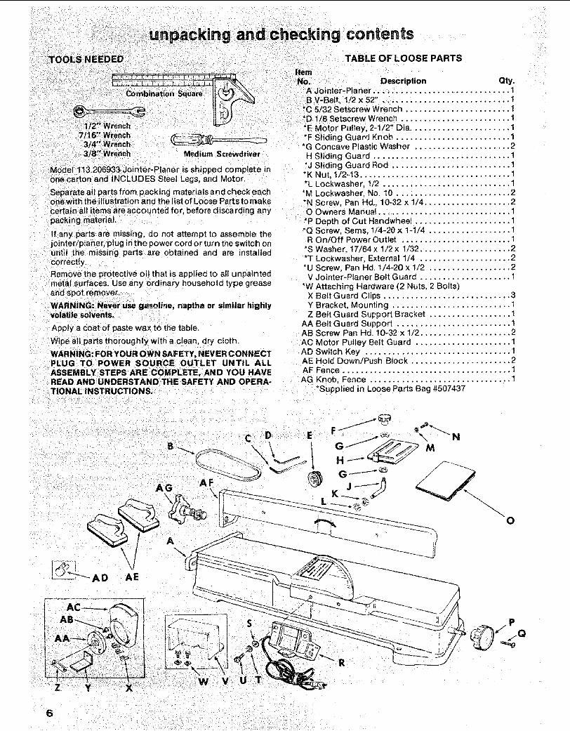
-//
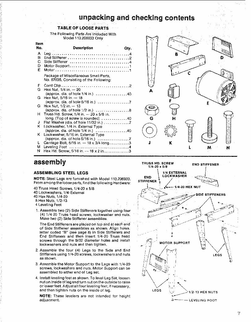
d checking contentsTABLE OF LOOSE PARTS
ItemNo. Description Qty.
A Jointer-Planer .............................. 1
7/:16" Wrench __3/4°'_Wrench3/8" Wrench Medium Screwdriver
M0def:113.206933 Jointer-Planer is shipped complete inonecarton and INCLUDES Steel Legs, and Motor.
Separate all parts from packing materials and check eachonewith the illustration and the list of Loose Parts to make
certain all items are accounted for, before discarding anypacking material.
If any: parts are missing, do not attempt to assemble thejointer/planer_ plug in the power cord or turn the switch onuntil the missing parts are obtained and are installedcorrectly.
Remove the protective oil that is applied to al{ unpaintedmetal surfaces. Use any ordinary household type grease
and spot remover.
WARNING: Never use gasoline, naptha or similar highlyvolatile solvents.
Apply a coat of paste wax to the table.
Wipe all parts thoroughly with a clean, dry cloth.
WARNING: FOR YOUR OWN SAFETY, NEVER CONNECTPLUG TO POWER SOURCE OUTLET UNTIL ALL
ASSEMBLY STEPS ARE: COMPLETE, AND YOU HAVE- READAND UNDERSTAND THESAFETY AND OPERA-T| ONAL INSTRUCTION S.
B V-Bett_ 1,/2 x 52" ............................ 1*C 5/32 Setscrew Wrench ....................... 1*D 1/8 Setscrew Wrench ........................ 1*E Motor Pulley, 2-1/2" Dia ...................... 1*F Sliding Guard Knob ......................... 1*G Concave Plastic Washer ..................... 2H Sliding Guard .............................. 1*J Sliding Guard Rod .......................... 1*K Nut, 1/2-13 ................................. 1*L Lockwasher, 1/2 ............................ 1*M Lockwasher. No. 10 ......................... 2*N Screw, Pan Hd., 10-32 x 1/4 ................... 2O Owners Mariu!! .............................. 1*P Depth of Cut Handwheet ..................... 1*Q Screw, Sems, 1/4-20 x 1-1/4 .................. 1
R On/Off Power Outlet ........................ 1*S Washer, 17/64 x 1/2 x 1/32 .................... 2"T Lockwasher. External 1/4 .................... 2*U Screw, Pan Hd. 1/4-20 x 1/2 .................. 2V Jointer-Planer Belt Guard .................... 1
*W Attaching Hardware (2 Nuts, 2 Bolts)X Belt Guard Clips ............................ 3Y Bracket. Mounting ......................... 1Z Beft Guard Support Bracket .................. 1
AA Bett Guard Support ......................... 1AB Screw Pan Hd. 10-32 x 1/2 .................... 2AC Motor Pulley Belt Guard ..................... 1AD Switch Key ................................ 1AE Hold Down/Push Block ...................... 2AF Fence ..................................... I
........ Fence ............................... I*Supplied in Loose Parts Bag #507437
AFAG
A
\ \
0
AD AE
6
:/
ItemNo.
unpacking and checking contentsTABLE OF LOOSE PARTS
TheFollowingPartsAreIn iudedWithModel 113,206933 Only
DescripUon Qty.
A Leg, .4B End Stiffener ............................... 2C Side Stiffener .............................. 4D Motor Support .............................. 1E Motor ..................................... 1
Package of Miscellaneous Small Parts,No. 67035, Consisting of the Following:
F Cord Clip .................................. 2G Hex Nut, 1/4 in.-- 20
(approx. dia. of hole 1/4 in,) ................ 40G Hex Nut, 5/16 in,-- 18
(approx. dla. of hole 5/16 in.) ................ 7G Hex Nut, 1/2 in.-- 13
(approx. dia. of hole 1/2 in.) ................. 8H TrussHd. Screw, 1/4in. --20x5/8 tn.
long. (Top of screw is rounded) ............. 40J Flat Washer (dia. of hole 11/32 in.) ............. 7K Lockwasher, 1/4 in. External Type
(approx. dia. of hole 1/4 in.) ................ 40K Lockwasher, 5/16 in, External Type
(approx. dia. of hote 5/16 in.) ................ 7L Carriage Bolt, 5/16 in. -- 18 x 3/4 tong .......... 3M Leveling Foot .............................. 4N Hex Hd. Screw, 5/16 in. -- 18 x 2 in ............. 3
ii i,, i ..................................
assembly
A
G
ASSEMBLING STEEL LEGS
NOTE: Steel Legs are furnished with Model 1t3.206933.From among the foose parts, find the foilowin 9 Hardware:
40 Truss Head Screws, I/4-20 x 5/840 Lockwashers, 1/4-External40 Hex Nuts, !/4-208 Hex Nuts, t/2-134 Leveling Feet
1. Assemble two (2) Side Stiffeners together Using four(4) 1/4-20 Truss head screws, tockwasher and nuts.Make two (2) Side Stiffener assemblies.
I
The End Stiffeners are placed on top and at each endof Side Stiffener assemblies as shown. Align holes,letter coded "B" (see page 8) in Side Stiffeners and ....-._ .....End Stiffeners and then insert 1/'4-20 Truss headscrews through the 9/32 diameter hotes and installIockwashers and nuts and then tighten.
2. Assemble the four (4) Legs to the Side and EndStiffeners using 1/4-20 screws, lockwashers and nutsas sh own, i
TRUSS HD. SCREW END STIFFENER
1/4-20 X _1/: EXTERNAL /END 1 LOCKWASHER __
MOTOR SUPPORT
STIFFENERS
LEGS
3. Assemble the Motor Support to the Legs with 1/4-20screws, Iockwashers and nuts. Motor Support can beassembled to either end of Leg set.
4. Install leveling feet as shown. To level Leg Set, loosennut on inside of leg and turn nut on the outside to raiseor lower feet. Adjust all four leveling feet, if necessary,and then tighten nuts on the inside of leg.
NOTE: These levelers are not intended for heightadjustment:
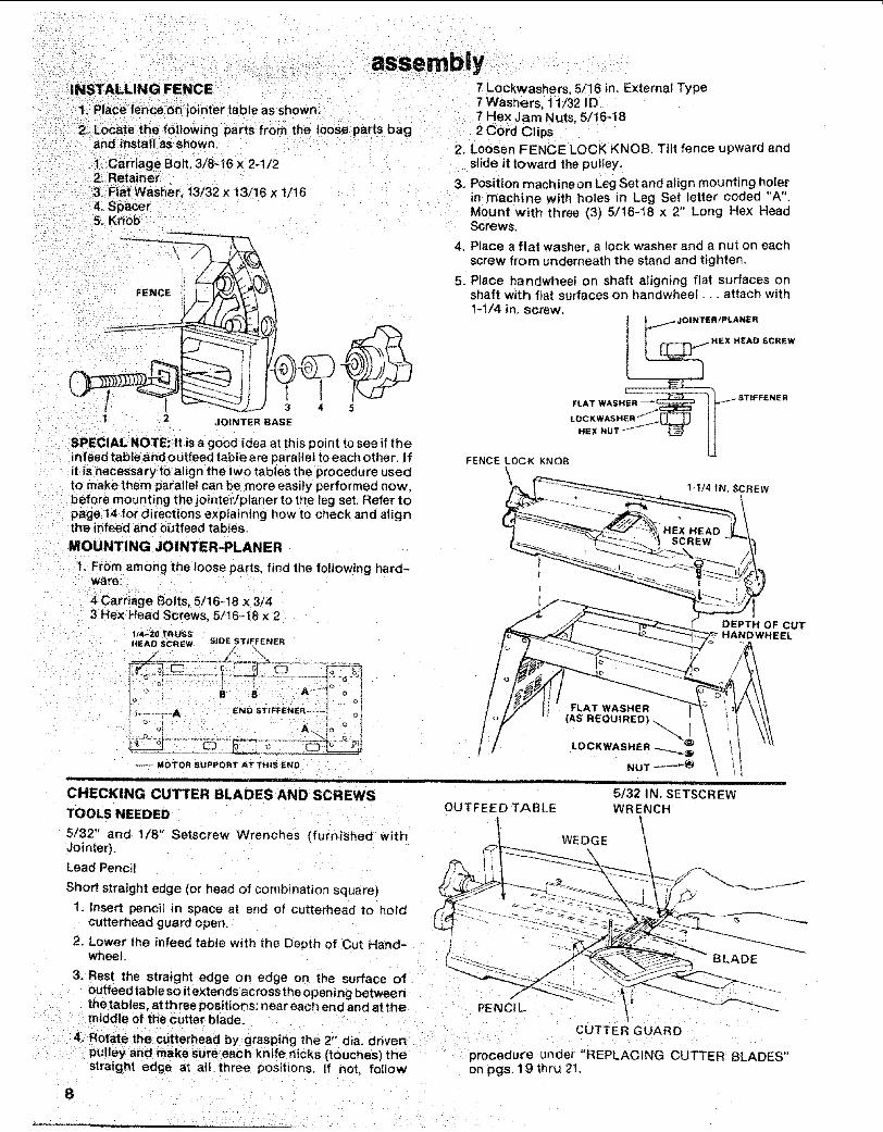
1. Place fence on jointer table as shown.
2_ Locate the following parts from the loose parts bagand install as shown.
1. CarriageBolt, 3/8-16 x 24/22. Retainer3, Fiat Washer 13/32 x 13/! 6 x 1/t64. Spacer5. =Knob
[E
1 2 JOINTER eASE
SPECIAL NOTE: It is a good _dea at this point to see if theinfeed table and Outfeed table are paraltel to each other. Ifit is necessary to align the two tables the procedure usedto make them parallel can be more easily performed now,before mounting the jointer/planer to the leg set, Refer topage 14 for directions explaining how to check and alignthe infeed and outfeed tables.
MOUNTING JOINTER-PLANER
1. From among the loose parts, find the following hard-ware:
assembly7 Lockwashers, 5/16 in. External Type7 Washers, 11/32 ID7 Hex Jam Nuts, 5/16-182 Cord Clips
2. Loosen FENCE LOCK KNOB, Tilt fence upward andslide it toward the pulley.
3. Position machine on Leg Set and align mounting holerin machine with holes in Leg Set letter coded "A'.Mount with three (3) 5/16-18 x 2" Long Hex HeadScrews.
4. Place a flat washer, a tock washer and a nut on eachscrew from underneath the stand and tighten.
5. Place handwheet on shaft aligning flat surfaces onshaft with flat surfaces on handwheel.., attach with1-1/4 in. screw.
_1_/ JOINTER ;PLANERHEX HEAD SCREW
1
HEXNOTff'_ Jl
FENCE LOCK KNOB
4Carriage Bolts, 5/16-18 x 3/43 Hex Head Screws, 5/16-18 x 2
_/4-_0 TRUSSHEAD SCREW SIDE STIFFENER
--- MOTOR SUPPORT AT THIS END
11 1
CHECKING CUTTER BLADES AND SCREWS
TOOLS NEEDED
5/32" and 1/8" Setscrew Wrenches (furnished withJointer).
Lead Pencil
FLAT WASHER
(AS REQUIRED) ..
LOCKWASHER
NUT ----"_
5/32 IN. SETSCREWOUTFEED TABLE WRENCH
WEDGE
DEPTH OF CUTEL
Short straight edge (or head of combination square)
1. Insert pencil in space at end of cutterhead to holdcutterhead guard open.
2. Lower the infeed table with the Depth of Cut Hand-wheel.
3. Rest the straight edge on edge on the surface ofoutfeed table so itextends across the opening betweenthe tables, at three positions: near each end and at themiddle of the cutter blade.
4. Rotate the cutterhead by grasping the 2" dia. drivenpulley and make sureeach knife nicks (touches) thestraight edge at all three positions. If not, follow
BLADE
PENCt L\
CUTTER GUARD
procedure under "REPLACING CUTTER BLADES"on pgs, 19 thru 21.
8
5. If a cutter blade adjustment is not required, checkeach locking screw of each wedge (5/32" setscrewwrench) and tighten if necessary. Hold the pulley
,i i --
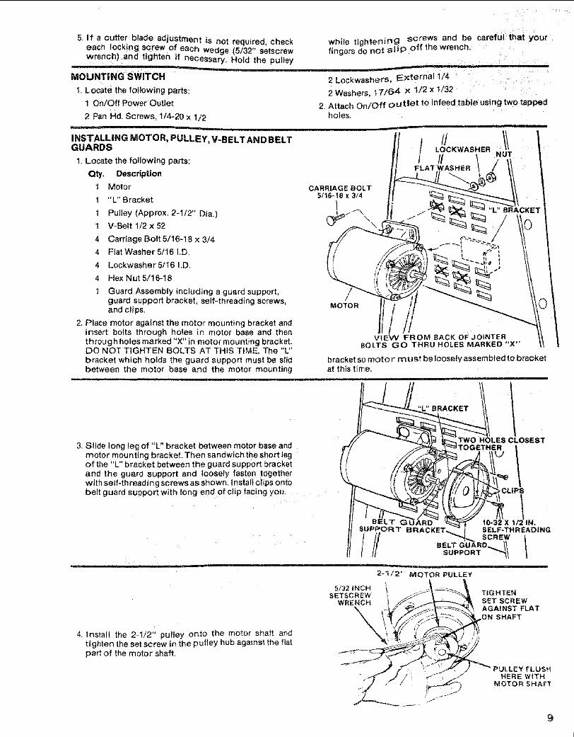
MOUNTING SWITCH
1, Locate the following parts:
1 On/Off Power Outlet
2 Pan Hd. Screws, 1/4-20 x 1/2
while tightening screws and be careful that yourfingers do not slip off the wrench-
2 Lockwash_rS, IE;<te real 1/4
2 Washers, 17/64 × 1/2 x 1732
2. Attach On/Off out|et to infeed table using two _appedholes.
i L __
INSTALLING MOTOR, PULLEY, V-BELT AND BELTGUARDS
1. Locate the following parts:
QIy. Description
1 Motor
1 "L" Bracket
1 Pulley (Approx. 2-1/2" Dia.)
1 V=Belt 1/2 x 52
4 Carriage Bolt 5/16-18 x 3/4
4 Fiat Washer 5/16 i.D.
4 Lockwasher5/16 I.D.
4 Hex Nut 5/16-!8
1 Guard Assembly _nctuding a guard support,guard support bracket, self-threading screws,and clips,
2. Place motor against the motor mounting bracket andinsert bolts through holes in motor base and thenthrough holes marked "X" in motor mounting bracket.DO NOT TIGHTEN BOLTS AT THiS TIME. The "L"bracket which holds the guard support must be slidbetween the motor base and the motor mounting
CARRIAGE BOLT5/16-18 x 3/4
MOTOR ti
VtEW FROM BACK OF JOINTERBOLTS GO THRU HOLES MARKED "X"
bracket somotor rn u st be loosely assembled to bracketat this time.
iii, IH i, iiiiiiii, ii
(
3. Slide long leg of "L" bracket between motor base andmotor mounting bracket. Then sandwich the short legof the "L" bracket between the guard support bracketand the guard support and loosely fasten togetherwith self-threading screws as shown. Install clips ontobett guard support with long end of clip facing you.
L¸ i_ j ill! i
TWO HOLES CLOSEST
10-32 X 1/2 IN,SELF-THREADING
suP.oRTi i i i !l , i iiiiii i _ url II I
2"!/2 '° MOTOR PULLEY
4. Install the 2-1/2" pulley onto the motor shaft andt_ghten the set screw in the pulley hub against the flatpart of the motor shaft.
5/32 INCHSETSCREW TIGHTEN
WRENCH S_T SCREWAGAINST FLAT
,ON SHAFT
HERE WITHMOTOR SHAFT
9
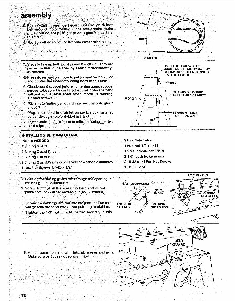
assembly ,. 5/Push V_Belt through belt guard just enough to loop
. belt aro'uhd motor pulley_ Place bett: around m0t()rpu ey but don0t push guard onto guard support at
: thistime. " - - -
6: Position other end of V-Belt onto cutter head pulley.
/ , i
7. Visually line up both pulleys and V-Belt until they are
perpendicular to the floor by sliding motor sidewaysas needed,
8. Pressdown hard on motor to put tension on the V-Beltand tighten the motor mounting bolts at this time.
9. Checkguard support before tightening guard supportscrews to be sure it is centered around motor shaft andwill not rub against shaft when motor msrunning.Tighten screws,
10. Push motor pulley belt guard into position onto guardsupport.
tl. Plug motor cord into outlet on switch box installedearlier through hole provided in stand.
12. Fasten cord along front side stiffener using the twocord clips.
i i i
INSTALLING SLIDING GUARD
OPEN ENDi i
PARTS NEEDED
1 Sliding Guard
1 Sliding Guard Knob
I Sliding Guard Rod
2 Sliding Guard Washers (one side of washer is concave)
2 Hex Hd. Screws 1/4-20x 1/2"
PULLEYS AND V-B ELT
j_MUST BE STRAIGHT IN-LINE_AT 90° WITH RELATIONSHIP
C_____ TO THE FLOOR!
t ,----V-BELT
GUARDS REMOVED..... ! FOR PICTURE CLARITY
i, t STRAIGHT LNE
// _,] \ , UP--DOWN90°
.... iJ, [ _
ill
2 Hex Nuts 1/4-20
1 Hex Nut 1/2 in. - 13
1 Split Iockwasher 1/2 in,
2 Ext. tooth Iockwashers
2 10-32 x 1/4 Pan Hd. Screws
1 Belt Guard
3, Screw the sliding guard rod into the jointer as far as itwitl go with the short end of rod pointing straight up.
4. Tighten the 1/2" nut to hold the rod securely in thisposition.
_I,POsitiOn the siiding:guard rod through the opening inthe belt guard as illustrated. 1/2" LOCKWASHER
2. Screw 1/2 °' nut alt the way onto long end of rod... \_ BELT
place 1/2" Iockwasher next to nut (as illustrated), _/i/4_:_ _ GUARD1/2" X t _/ .//_ \SLIDING
HEX NUT [i _/ GUARD RODt/
1/2" HEX NUT
GUARD ROD
5. Attach guard to stand with hex hd. screws and nuts,Make sure belt does not scrape guard,
10
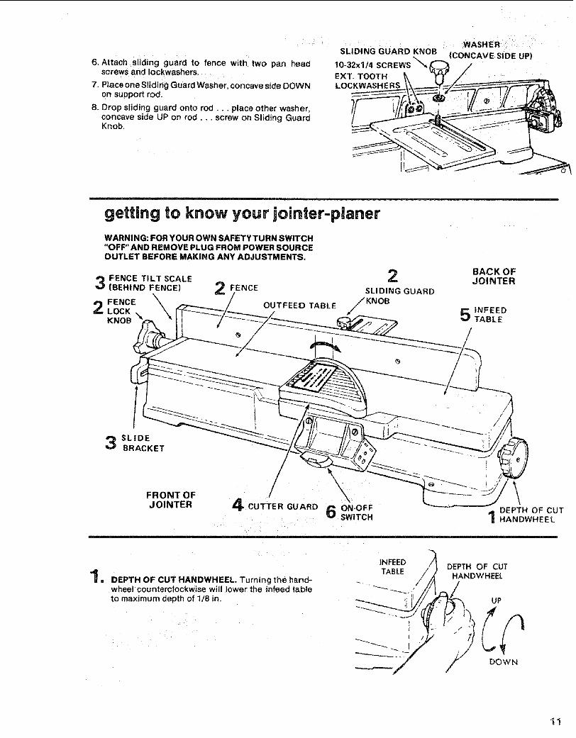
SLIDING GUARD KNOB
6. Attach sliding guard to fence with two pan head 10-32xl/4 SCREWS'_',,_screws and Iockwashers. EXT. TOOTH
7. PtaceoneSIidingGuardWasher, concaveside DOWN LOCKWASHERSon support rod.
8. Drop sliding guard onto rod.., place other washer,concave side UP on rod.. _screw on Sliding GuardKnob.
_,^o==o,,M=,,,_,_ '
(CONCAVE S|DE UP)
i,, u,i i llUl ,1= == ===LI H i i
getting to know your jointer-planerWARNING: FOR YOUR OWN SAFETYTURN SWITCH"OFF" AND REMOVE PLUG FROM POWER SOURCEOUTLET BEFORE MAKING ANY ADJUSTMENTS.
FENCE TILT SCALE(BEHIND FENCE)
FENCELOCKKNOB
FENCE
OUTFEE{) TABLE
2SLIDING GUARD
F KNOB
BACK OFJOINTER
INFEEDTABLE
SLIDEBRACKET
!
FRONT OF \,%
JOINTER 4 CUTTER GUARD 6 ON-OFF DEPTH OF CUTSWITCH 1 HANDWHEEL
1NFEED DEPTH OF CUT..41 TABLE
= DEPTH OF CUT HANDWHEEL Turning the hand- /I
HANDWHEEL
wheel counterclockwise will lower the infeed table _"_---_+.'to maximum depth of 1/8 in. UP
/.i/ DOWN
I"1
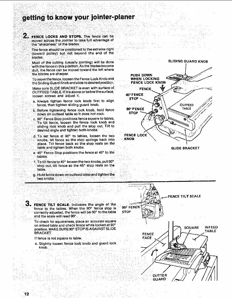
_- = FENCE LOCKS AND STOPS.= The fence can be
moved across the Jointer to take full advantage of1he "sharpness_' Of the blades.
Thb fence should be positioned to the extreme right(toward pulley) but not beyond the end of the
blades.
Most of the cutting (usually jointing) will be done-. w_th thefence in this position, As the blades become• .dull, the fence can be moved toward the left where
the blades are sharper,
To move the fence, loosen the Fence Lock Knob andthe Sliding Guard Knob and slide to desired position.
Make sure SLIDE BRACKET is even with surface ofOUTFEED TAB LE. If it is above or below the surface,loosen screws and adjust it.
a. Always tighten fence lock knob first to alignfence, then tighten sliding guard knob.
b. Before tightening fence lock knob, hold fencedown on outfeed table so it does not rock.
c. 90 ° Fence Stop positions fence square to tables.TO tilt fence, loosen the fence lock knob andsliding lock knob and pull the stop out. Tilt todesired angle and tighten both knobs.
d. To set fence at g0 ° to tables, loosen the twoknobs, tilt fence so the stop springs back intoplace. Tilt fence back so the stop rests on thetable and tighten both knobs.
e. 45 ° Fence Stop positions the fence at 45 ° to thetables.
f. To tilt fence to 45 ° loosen the two knobs, pull 90 °stop out, t It:fence so the 45 ° stop rests on thetable.
g. Ho d fencedown on outfeed table and tighten thetwokn0bs: " " : ' : :
i i i i ii i i
. FENCE TILT SCALE. Indicates tf_e angle of thefence to the tables. When the 90_ fence stop iscorrectly adjusted, the fence will be 90 ° to the tableand the scale will read 90 °.
To check for squareness, place an accurate square
PUSH DOWNWHEN LOCKINGFENCE LOCK KNOB
FENCE
45°FENCESTOf
_°FENCESTOP
FENCE LOCK .KNOB \
\
SLIDING GUARD KNOB
SLIDE BRACKET
._..---FENCE TILT SCALE
on infeed table and check fence while locked at 90°position. MAKE SURE 90° STOP IS AGAINST SLIDEBRACKET.
If fence is not square to table:
a. Slightly loosen fence lock knob and guard lockknob ....
FENCEFACE
SQUARE
/" CUTTER
GUARD
1NFEEDTABLE
12
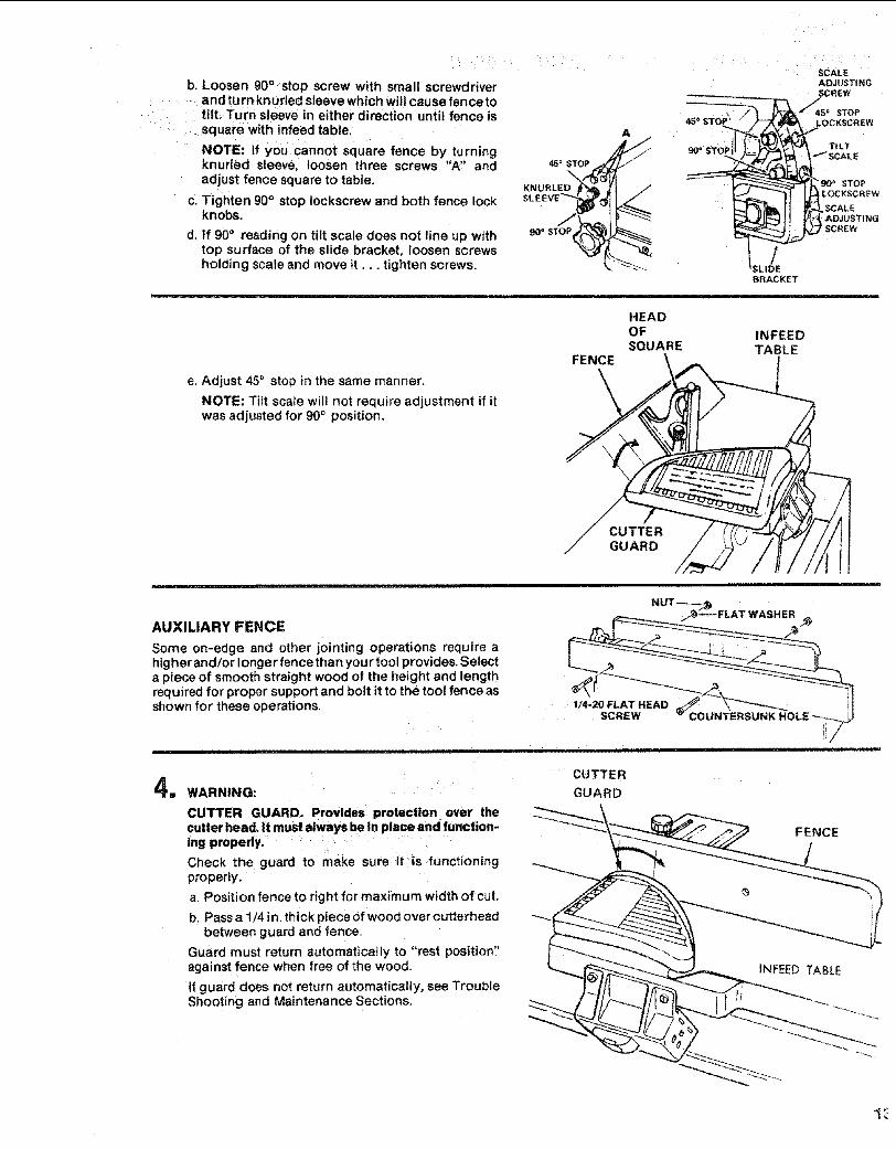
b. Loosen 90° stop screw with small screwdriverand turn knurled sleeve which will cause fence totilt, Turn sleeve in either direction until fence issquare with infeed table.
NOTE: If you cannot square fence by turningknuded sleeve, loosen three screws "A" andadjust fence square to table.
c. Tighten 90° stop Iockscrew and both fence lockknobs,
d, If 90° reading on tilt scale does not line up withtop surface of the slide bracket, loosen screwsholding scale and move it... tighten screws.
45 = STOP
KNURLED J_
SLEEVEN_(
90 e STOP
e. Adjust 45° stop in the same manner.
NOTE: Tilt scale wilt not require adjustment if itwas adjusted for 90 ° position.
45_'STO_
90° STOP
zF
HEADOFSQUARE
FENCE
SCALEADJUSTINGSCREW
_s o sToPLOCKSCREW
TiLT
SCALE
'gO '_ STOPLOCKSCREW
SCALEAD3USTINGSCREW
BRACKET
INFEEDTABLE
CUTTERGUARD
AUXILIARY FENCE
Some on-edge and other jointing operations require ahigher and/or Ionge r fence than you r tool provides. Selecta piece of smooth straight wood of the height and lengthrequired for proper support and bolt it to the tool fence asshown for these operations, 1/4-20 FLAT HEAD
SCREW COL
11 WARNING:
CUTTER GUARD. Provides protection over the
cutter head. It must always be in PlaCe and function-ing properly. ....
Check the guard to make sure it is functioningproperly.
a. Position fence to right for maximum width of cut.
b. Pass a 1/4 in. thick piece of wood over cutterheadbetween guard and fence,
Guard must return automatically to "rest position"against fence when free of the wood,
tf guard does not return automatically, see TroubleShooting and Maintenance Sections.
CUTTER
GUARD
FENCE
INFEED TABLE
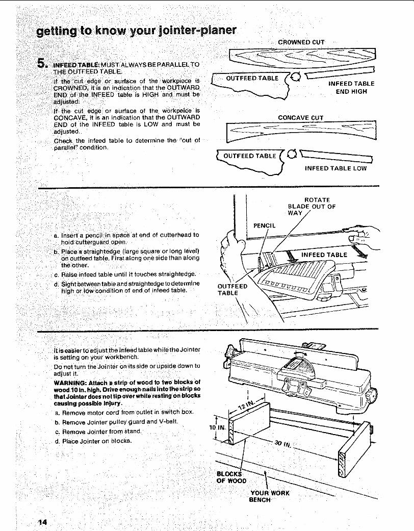
to know your jointer.planer
A ALWAYS BE PARALLEL TO
or lrfac. _ of the w0rkpiece isan iicati on that the OUTWARD
qFEED table is HiGH and must be
CROWNED CUT
or surface of the workpeice isCONCAVE, it is an ind tcation that the OUTWARDEND of the fNFEED table is LOW and must beadjusted.
Check the infeed table to determine the "out of
parallel" condition.
CONCAVE CUT
INFEED TABLE LOW
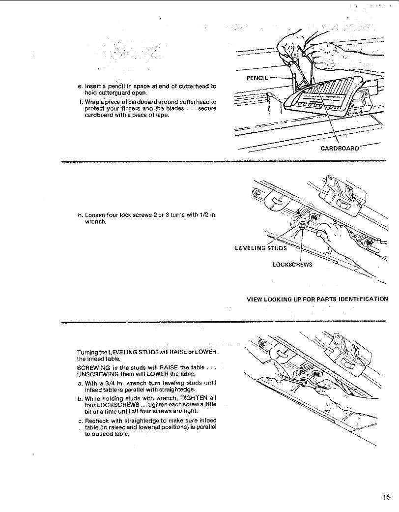
a, Insert a penciHn space at end of cutterhead tohold cutterguard open.
b, Place astraightedge (large square or long level)on outfeed table. First along one side than alongtheother.
C. Raise infeed table until it touches straightedge.
d. Sight between tabte and straightedge to determinehigh or!ow condition of end of infeed table.
= =ll
i l] w,y
PENCIL ",
TABLE _ _-_" J__
it iseasier to adjust the infeed table while the Jointeris setting on your workbench.
Do not turn the3ointer on its side or upside down toadjust it.
WARNING: Attach a strip of wood to two blocks ofwood 10 in. high. Drive enough nails into thestrlp sothat Jointer does not ti p over while resting on blockscausing possible injury,
a. Remove motor cord from outlet in switch box.
b. Remove Jointer pulley guard and V-belt.
c. Remove Jointertrom stand.
d. Place Jointer on blocks.
OF WOOD
YOUR WORKBENCH
e. Insert a pencil in space at end of cutterhead tohold cutterguard open.
f. Wrap a piece of cardboard around cutterhead toprotect your fingers and the btades.., sec_urecardboard with a piece of tape.
JCARDBOARD-
h. Loosenfourlockscrews 2 or3turns withl/2in.wrench.
LEVELING STUDS
LOCKSCREWS
VIEW LOOKING UP FOR PARTS IDENTIFICATION
Turning the LEVELING STUDS will RAISE or LOWERthe infeed table.
SCREWING in the studs will RAISE the table ....UNSCREWING them wilt LOWER the table.
a. With a 3/4 in. wrench turn leveling studs untilinfeed table is parallel with straightedge.
b. While holding studs with wrench, TIGHTEN allfour LOCKSCREWS... tighten each screw a littlebit at a time until alt four screws are tight.
c. Recheck with straightedge to make sure infeedtable (in raised and lowered positions) is paralletto ouffeed table.
\
15
j'ointer- pianer
be turned=ched or bumped,
OFF"by strikinge hand.
n" is a key, when inserted in theturned ON and OFF.
it is removed, the power cannot be turned ON.
THIS FEATURE tS INTENDED TO PREVENTUNAUTHORIZED AND POSSIBLE HAZARDOUSUSE BY CHILDREN AND OTHERS.
a. Insert Key into switch,
NOTE: Key is made of yellow plastic,
b. TO turn machine on, insert finger under switchlever and pull end Of switch out.
NOTE: Key is made of vellow plastic.
i i
c, To turn machine OFF PUSH lever in.
Never leave machine unattended until it hascome to a complete step.
d. TO lock switch in OFF position .. : hold switch INwith onehand ... REMOVE key with other hand.
WARNING: FOR YOUR OWN SAFETY, ALWAYSLOCK THE SWITCH "OFF" WHEN MACHINE ISNOT IN USE... REMOVE KEY AND KEEP tT IN ASAFE PLACE,., ALSO... IN THE EVENT OF APOWER FAILURE (ALL OF YOUR LIGHTS GOOUT) TURN SWITCH OFF... AND REMOVE THEKEY. THIS WILL PREVENT THE MACHINE FROMSTARTING UP AGAIN WHENTHE POWER COMESBACK ON.
\
HOLD
PULL
MOTORCORD
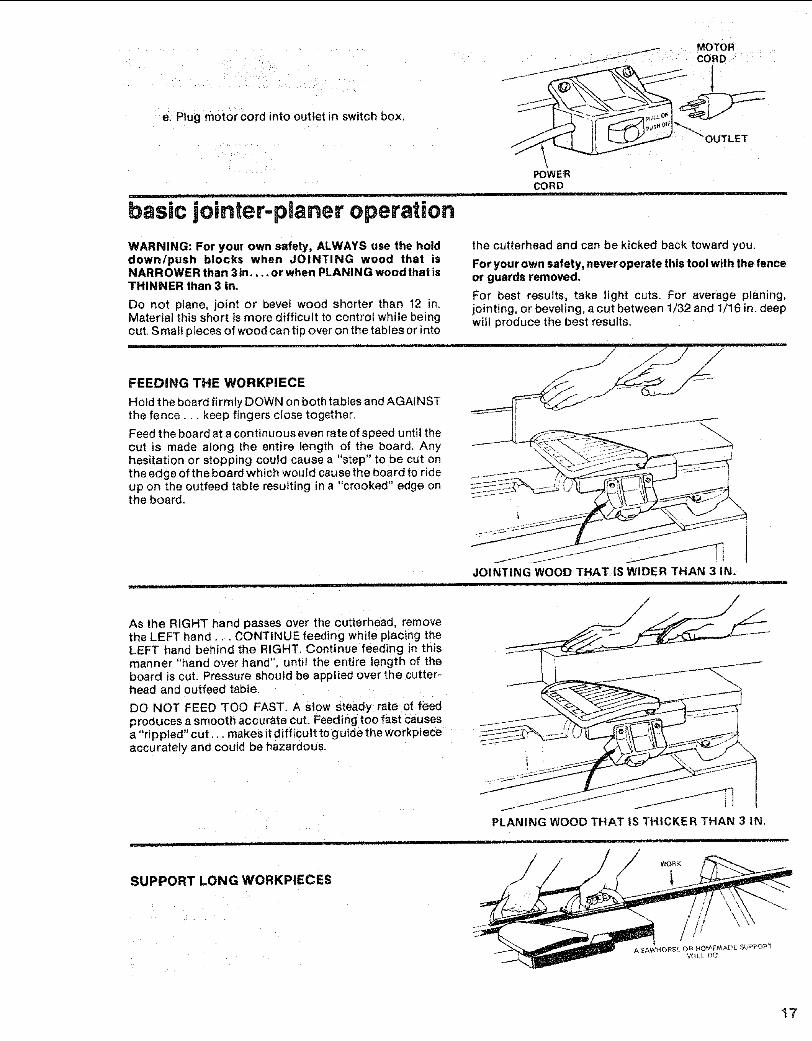
te. Plug motor cord into outlet in switch box,
OUTLET
-- i i _1 ii ___
basic jointer-planer operation
POWERCORD
WARNING: For your own safety, ALWAYS use the holddown/push blocks when JOINTING wood that isNARROWER than 3 tn.... or when PLANING wood that isTHINNER than 3 in.
Do not plane, joint or bevel wood shorter than 12 in.Material this short is more difficult to control while beingcut. S mall pieces of wood can tip over on the tables or into
, , , i
the cutterhead and can be kicked back toward you.
For your own safety, never operate this tool with the fenceor guards removed.
For best results, take light cuts. For average planing,jointing, or beveling, a cut between t/32 and t/16 in. deepwill produce the best results.
FEEDING THE WORKPIECE
Hold the board firmly DOWN on both tables and AGAINSTthe fence.., keep fingers close together.
Feed the boa rd at a continuous even rate of speed u ntil thecut is made along the entire length of the board. Anyhesitation or stopping could cause a "step" to be cut onthe edge of the board which would cause the board to rideup on the outfeed table resulting in a "crooked" edge onthe board.
i1,1 , iiil,,irl
JOINTING WOOD THAT IS WIDER THAN 3 IN.
As the RIGHT hand passe s over the cutterhead, removethe LEFT hand... CONTINUE feeding while placing theLEFT hand behind the RIGHT. Continue feeding in thismanner "hand over hand", until the entire length of theboard is cut. Pressure should be applied over the cutter-head and outfeed table.
DO NOT FEED TOO FAST. A stow steady: rate of feedproduces a smooth accurate cut. Feeding too fast causesa "rippled" cut,., makes it difficult to guide the workpiece ....accurately and could be hazardous.
i i iiii iii1,1 i ,HI
PLANING WOOD THAT IS THICKER THAN 3 IN.
SUPPORT LONG WORKPIECES
17
basic jointer-planer operation
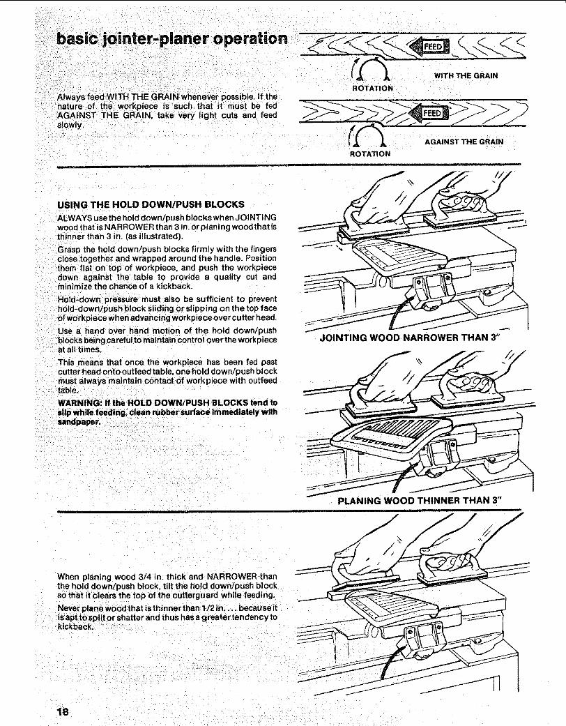
_ver 1natuAGAINST THE GRAIN, take very light cuts and feedslowly,
ROTATION
ROTATION
WITH THE GRAIN
AGAINST THE GRAIN
USING THE HOLD DOWN!PUSH BLOCKS
ALWAYS use the hold down/push blocks when JOINTINGwood that is NARROWER than 3 in. or planing wood that isthinner than 3 in. (as illustrated).
Grasp the hold down/push blocks firmly with the fingersclose together and wrapped around the handle. Positionthem flat on top of workpiece, and push the workpiecedown against the table to provide a quality cut andminimize the chance of a kickback.
Hold-down pressure must also be sufficient to preventhold-down/push block sliding or slipping on the top faceof workpiece when advancing workpiece over cutter head.
Use a hand over hand motion of the hold down/pushblocks being careful to maintain control over the workpieceat all times:
This means that once the workpiece has been fed pastcutter head onto outfeed table, one hold down/push blockmust always maintain contact of work piece with ouffeedtable.
WARNING: If the HOLD DOWNIPUSH BLOCKS tend to
slip while feeding, Clean rubber surfacelmmediately withsandpaper. _:
JOINTING WOOD NARROWER THAN 3"
%
PLANING WOOD THINNER THAN 3"i
Z
When planing wood 3/4 in. thick and NARROWER thanthe hold down/push block, tilt the hotd down/push blockso that it clears the top of the cutterguard while feeding,
Never plane wood that is thin net than 1/2 in .... because itsapt to spiitor shatter and th us has a greater ten dency to
kickback.: - "
18
k
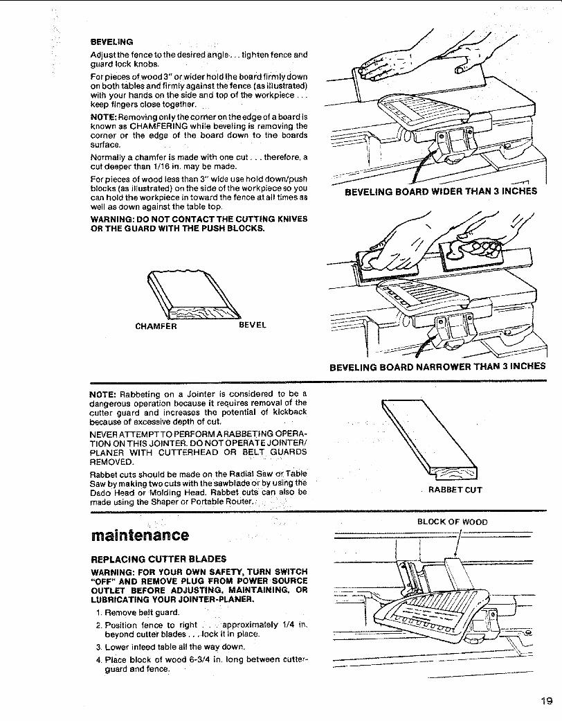
BEVELING
Adjust the fence to the desired angle.., tighten fence andguard lock knobs ......
For pieces of woo d 3" or wider hold the board firmlydownon both tables and firmly against the fence (as illustrated)with your hands on the side and top of the workpiece,..keep finge_s close together.
NOTE: Removing only the corner on the edge of a board isknown as CHAMFERING while beveling is removing thecorner or the edge of the board down to the boardssurface.
Normally a chamfer is made with one cut,., therefore, acut deeper than 1/16 in. may be made,
For pieces of wood less than 3" wide use hold down/pushblocks (as illustrated) on the side of the workpiece so youcan hotd the workpiece in toward the fence at all times aswell as down against the table top.
WARNING: DO NOT CONTACT THE CUTTING KNIVESOR THE GUARD WITH THE PUSH BLOCKS.
BEVELING BOARD WIDER THAN 3 INCHES
CHAMFER BEVEL
BEVELING BOARD NARROWER THAN 3 iNCHES
NOTE: Rabbeting on a Jointer is considered to be adangerous operation because it requires removal of thecutter guard and increases the potential of kickbackbecause of excessive depth of cut .....
NEVER ATTEMPTTO PERFORM A RABBETING OPERA-TION ON THIS JOINTER. DO NOT OPERATE JOtNTER/PLANER WITH CUTTERHEAD OR BELT GUARDSREMOVED.
Rabbet cuts should be made on the Radial Saw or TabteSaw by making two cuts with the sawblade or by using theDado Head or Molding Head. Rabbet cuts can also bemade using the Shaper or Portable Router.:
i
, i
maintenance
RABBETCUT
::i• IHUlhUlN ........=
BLOCK OF WOOD
REPLACING CUTTER BLADES
WARNING: FOR YOUR OWN SAFETY, TURN SWITCH"OFF" AND REMOVE PLUG FROM POWER SOURCEOUTLET BEFORE ADJUSTING, MAINTAINING, ORLUBRICATING YOUR JOINTER-PLANER,
1. Remove be!t guard.
2. Position fence to right ,.. approximately 1/4 in,beyond cutter blades.., lock it in place,
3. Lower infeed table all the way down,
4. Place block of wood 6-3/4 in, long between cutter-guard and fence:
/
19
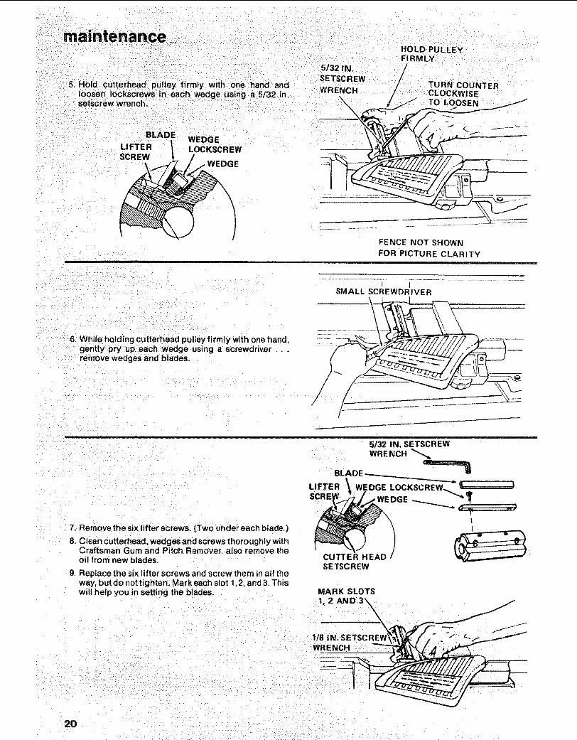
5. Hold cutterhead pulley firmly with one hand and
loosen iockscreWs in each wedge using a 5/32 in.Setscrew wrench.
BLADEWEDGE
LIFTER LOCKSCREWSCREW
i
5/32 IN.SETSCREW
WRENCH
HOLD PULLEYFIRMLY
CLOCKWISELOOSEN
FENCE NOT SHOWN
FOR PICTURE CLARITYj
6. While holding Cutterhead pulley firmly with one hand,gentlypry up each Wedge using a screwdriver . .remove wedges and blades.
SMALL SCREWDRIVER
!
7. Remove the six lifter screws. (Two under each blade.)
8. Clean cutterhead, weoges and screws thoroughly withCraftsman Gum and Pitch Remover. also remove theoil from new blades.
9. Replace the six lifter screws and screw them in all theway, but do not tighten. Mark each slot 1,2, and 3. Thiswitl help you in setting the blades.
CUTTER HEAD 'SETSCREW
MARK SLOTS
1, 2 AND 3X
!/8 IN. SETSCREVWRENCH
2O
I/8 IN, SETSCREW WRENCH
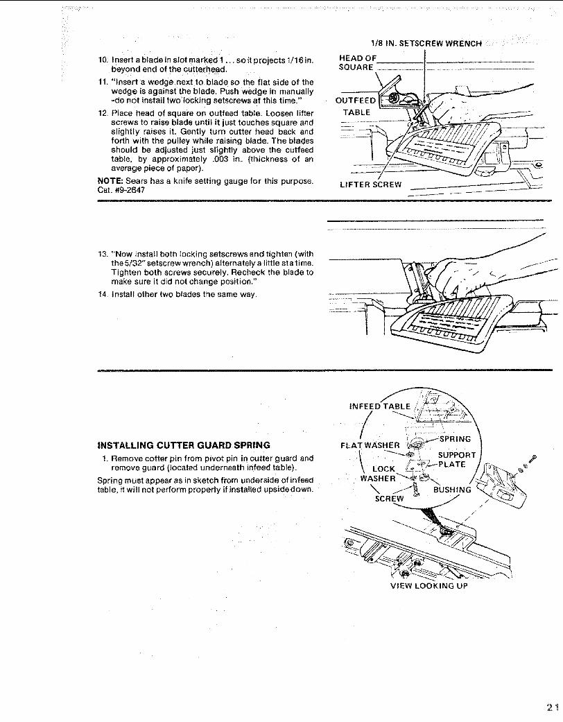
10. Insert a blade in slot marked I .,. so it projects t/16 in.beyond end of the cutterhead,
11. "Insert a wedge next to blade so the flat side of thewedge is against the bla(_e. Push wedge in manually-do not install two locking setscrews at this time."
!2, Place head of square on outfeed table. Loosen lifterscrews to raise blade until it just touches square andslightly raises it. Gently turn cutter head back andforth with the pulley while raising blade. The bladesshould be adjusted just slightly above the cutfeedtable, by approximately .003 in. (thickness of anaverage piece of paper).
NOTE: Sears has a knife setting gauge for this purpose.Cat. #9-2647
HEAD OFSQUARE ........
OUTFEED_
LIFTER SCREW
...... ii ,lllllr,i!iN,llll ii iii i
13. "Now install both locking setscrews and tighten (withthe 5/32" setscrew wrench) alternately a little at atime.Tighten both screws securely. Recheck the blade tomake sure it did not change position."
14. Install other two blades the same way.
INFEE
/
INSTALLING CUTTER GUARD SPRING FLAT WASHER _zSPRtNG
t. Remove cotter pin from pivot pin in cutter guard and _"-'-_ !_ SUPPORTremove guard (located u_derneath infeed table). _ LOCK _-_ 7"_PLATE
Spring must appear as in sketch from underside of infeed WASHE R_"_.._ /
table, it will not perform properly if nsta ed upside down. _ _ BUSHINGSCREW
//
./
VIEW LOOKING UP
2I
maintenance
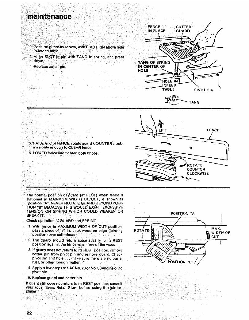
2. Position guard as shown with;PIVOT PIN above holein infeedtable.
3, Align SLOT in pin With TANG in spring, and pressdown.
4i Replace cotter pin.
FENCEIN PLACE
TANG OF SPRINGIN CENTER OFHOLE
CUTTERGUARD
'1 iii ii i
PIVOT PIN
5. RAISE end of FENCE, rotate guard COUNTER clock-wise only enough to CLEAR fence,
6. LOWER fence and tighten both knobs.
\LI FT
COUNTERCLOCKWISE
FENCE
= =
The normal position of guard (at REST) when fence isstationed at MAXIMUM WIDTH OF CUT. is shown as"position "A". NEVER ROTATE GUARD BEYOND POSI-TION "B" BECAUSE THIS WOULD EXERT EXCESSIVETENSION ON SPRING WHICH COULD WEAKEN ORBREAK IT.
Check operation of GUARD and SPRING.
1. With fence in MAXIMUM WIDTH OF CUT position,pass a piece of 1/4 in, thick wood on edge (jointingposition) over cutterhead.
2. The guard should return automatically to its RESTposition against the fence when free of the wood.
3. If guard does not return to its REST position, removecotter pin from pivot pin and remove guard. Checkpivot pin and hole.., make sure there are no burrs,rust, or other foreign matter.
4. Apply a few drops of SAE No. 20 or No, 3Oengine oil topivot pin.
5. Replace guard and cotter pin.
POSIT1 ON °'B"i,J /
If guard still does not return to its REST position consultyour local Sears Retail Store before using the jointer- :planer.
[MAX.WIDTH OFCUT
!
22 - i:
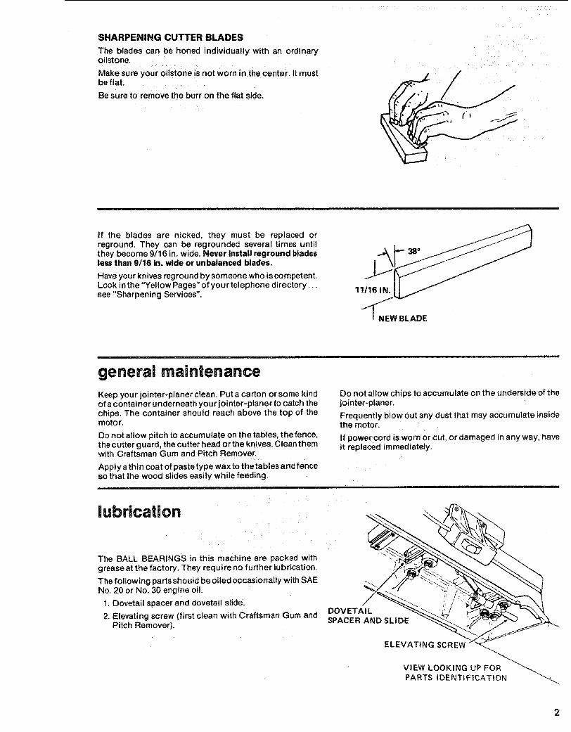
SHARPENING CUTTER BLADES
The blades can be honed individually with an ordinaryoilstone.
Make sure your oilstone is not worn in the center. It mustbe fiat.
Be sure to remove the burr on the fiat side.
//
/
If the blades are nicked, they must be replaced orreground. They can be regrounded several times untilthey become 9/16 in. wide. Never install reground bladesless than 9/16 in. wide or unbalanced blades.
Have your knives reground by someone who is competent.Look in the "Yellow Pages" of your telephone directory...see "Sharpening Services".
11116 IN,
NEW BLADE
........................................ i1=rll i=
general maintenanceKeep your jointer_planer clean. Put a carton or some kindof a container underneath your jointer-planer to catch thechips. The container should reach above the top of themotor.
Do not allow pitch to accumulate on the tables, the fence.the cutter g uard, the cutter head or the knives. Clean themwith Craftsman Gum and Pitch Remover.
Apply a thin coat of paste type wax to the tables and fenceso that the wood slides easily while feeding.
Do not atlow chips to accumulate on the underside of thejointer-planer.
Frequently biow out any dust that may accumulate insidethe motor.
If power cord iis worn or cut, or damaged in any way, haveit replaced immediately:
lubricaUon
The BALL BEARINGS in this machine are packed withgrease at the factory. They require no further lubrication.
The following parts should be oiled occasionally with SAENo. 20 or No. 30 engine oil.
1. Dovetail spacer and dovetail slide.
2. Elevating screw (first clean with Craftsman Gum andPitch Remover).
DOVETAILSPACER AND SLIDE
ELEVATING SCREW '
VIEW LOOKING UP FOR
PARTS IDENTIFICATION

MOTOR MAINTENANCE AND LUBRICATION
1. The bearings, in both end shields of the motor, havebeen lubricated at the factory with €orrect lubricant.NO Other part of the motor requires lubrication.
2_Re-lubricate motor bearings in accordance with theinstrgctions on the nameplate. Be sure to wipe off dirtor grit if present around oil hole caps to prevent anypossibility of foreign material contaminating the oilwicks that supply the bearings with oil. Use a good
-grade of medium weight mineral oil, such as automo-bile engine noii, SAE 20.
3. If disassembly of the motor is necessary, it should bereturned to your neareast Sears retail or mail-orderstore in order to prevent voiding the guarantee.
NOTE: The speed of this motor cannot be regulated orchanged.
4. Every effort shou Id be made to prevent foreign materialfrom entering the motor. When operated under cond|-tions likely to permit accumulations of dust, dirt, orwaste within the motor, a visual inspection should bemade at frequent intervals. Accumulations of dry dustcar'; usually be blown out successfully.
NOTE: Motors used on wood-working tools areparticularly susceptible to the accumulation of sawdustand wood chips and should be blown out or"vacuumed" frequently to prevent interference withnormal motor ventilation and proper operation of thecentrifugally-operated starting switch.
trouble shooting
WARNING: FOR YOUR OWN SAFETY, TURN SWITCH "OFF" AND REMOVE PLUG FROMPOWER SOURCE OUTLET BEFORE TROUBLE SHOOTING YOUR JOINTERPLANER.
TROUBLE SHOOTING CHART
TROUBLE PROBABLE CAUSE REMEDY
1. Defective On-Off switch. 1. Replace defective parts before using machine again.Defective switch cord.Defective switch box
receptacle.
- 2. Motor protector open (only 2, Consult Sears Service. Any attempt to repair this motor- : if your motor is equipped may create a HAZARD unless repair is done by a
.... : wi:th an ovedoad protector), qualified service technician. Repair service ls available
table after passing over , below surface of outfeed table.
Ripples on planed 1, One blade set higher than 1. Re-adjust btades, see Maintenance section.surface, I other.
2. Feeding wood too fast. 2. Feed wood slower.
Planed surface not Infeed table out of adjustment. Re-adjust infeed table, see Getting To Know your Jointer'straight. , Planer section.
Excessive gouging at Blades set too h gh above Reset blades, see Maintenance section.end of cut. outfeed table.
90 ° and 45° cuts 1. Fence stops not adjusted 1. Re-adjust fence stops, see Getting To Know yourinaccurate, properly. Jointer Planer section+
2. Fence slide bracket not 2. Re-adjust slide bracket, see Getting To Know your• even with table. Jointer Planer section.
InrOad table loose, l l Dovetail spacer requires 1. Tighten screw, key lO, see fig, 3 Parts List., adjustment, i
2. Female dovetail loose from! 2. Tighten screws, key 17, see fig. 3, Parts List.
.... t table. : i ...........
Cutter guard does not 1. Return spring brokeni or 1 Replace spring immediately. See Maintenance section.function properly, spring has been weakened_ : :.... " _ .... _ 2. improper assembly of 2. See Maintenance section.
I spring or guard mounting.

TROUBLE SHOOTING -- MOTOR .......
NOTE: Motors used on wood-working tools are particularly susceptible to the accumulationof Sawdust and wood chips and should be blown out or "vacuumed" frequentiy to prevent =interference with normal motor ventilation and proper operation of the centrifugally-operated starting switch. , '
TROUBLE PROBABLE CAUSE REMEDY
Excessive noise. 1, Motor,
Motor fails to developfull power, NOTE:LOW VOLTAGE: (Poweroutput of motordecreases rapidly withdecrease in voffage atmotor terminals. For
example, a reduction of10% in voltage causes areduction of 19% inmaximum power output
of which the motor iscapable, and a reductionof 20% in voltage causesa reduction of 36% inmaximum power output.)
Motor starts slowlyor fails to come upito full speed,
Motor overheats.
Starting switch in motorwilt not operate.
Motor stalls (resultingin blown fuses ortripped circuit breakers),
Frequent opening offuses or circuitbreakers.
1. Circuit overloaded withlights, appliances and othermotors.
2r Undersize wires or circuittoo long.
3. General overloading ofpower company facilities.
!. Low voltage will not triprelay,
2. Windings burned outoropen.
3. Starting relay not operating.
!. Motor overloaded.2. Improper cooling. (Air
circulation restrictedthrough motor due tosawdust, accumulatinginside of motor).
1. Burned switch contacts(due to extended hold-inperiods caused by low linevoltage, etc.).
2. Shorted capacitor.3. Loose =or broken
connections.
1. Starting switch notoperating.
2. Voltage too tow to permit:motor to reach operatingspeed!
3. Fuses or circuit breakersdo not have sufficientcapacity.
1. Motor overloaded.2. Fuses or circuit breakers
do not have sufficientcapacity.
3, Startring switch notoperating (motor does notreach speed).
1, Have motor checked by qualified service technician.Repair service is available at your nearest Sears store.
t. Do not use Other appliances or motors on same circuitwhen using the jointer.
2. Increase wire sizes, or reduce length of wiring. See"Motor Specifications and Electrical Requirements"section.
3. Request a voltage check from the power company.
1. Request voltage check from the power company.
2. Have motor repaired or replaced.
3. Have relay replaced.
1. Feed work slower into blade.2. Clean out sawdust to provide normal air circulation
through motor. See "Maintenance and Lubrication"section.
1. Have switch replaced and request a voltage checkfrom the power company.
2. Have capacitor tested and replace if defective.3. Have wiring checked and repaired.
1. Have switch replaced.
2. Request voltage check from the power company.
3. Install proper size fuses or circuit breakers.
1. Feed work slower.2. install proper size fuses or circuit breakers.
3. Have switch replaced.
2
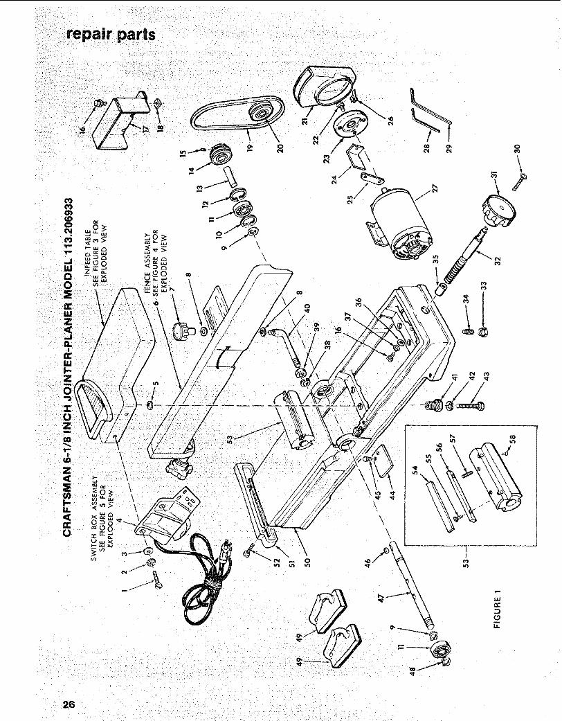
repair paris
\
26
Li.

eo
o
o_
w E00 z
2:."i
wEZ
"J I_
_z_,.
m _
Z<
h-
-n"o
d0
o -0 cont .-_"
_ 0 _ ^_
•_ _ 0._- _
x O- _ l'_? O_Z_oE _.oxo
._r -- _ 0_
mm0 "r nO 00 _ _0 _0 m 0+
_ 0 o_ _ o
z o_ ____o__
0
o
-- _ "0 "- 0 "r
• 0 0 ,- o F_"
_r_ 0 ....... _o!_ _ , _.m -- m _ x × •
_00_ r_ _ 0 - - _ 0 0 00_ 0 0
0E
c o
tG
_>. oO
z Eb5
+
27
repair parts
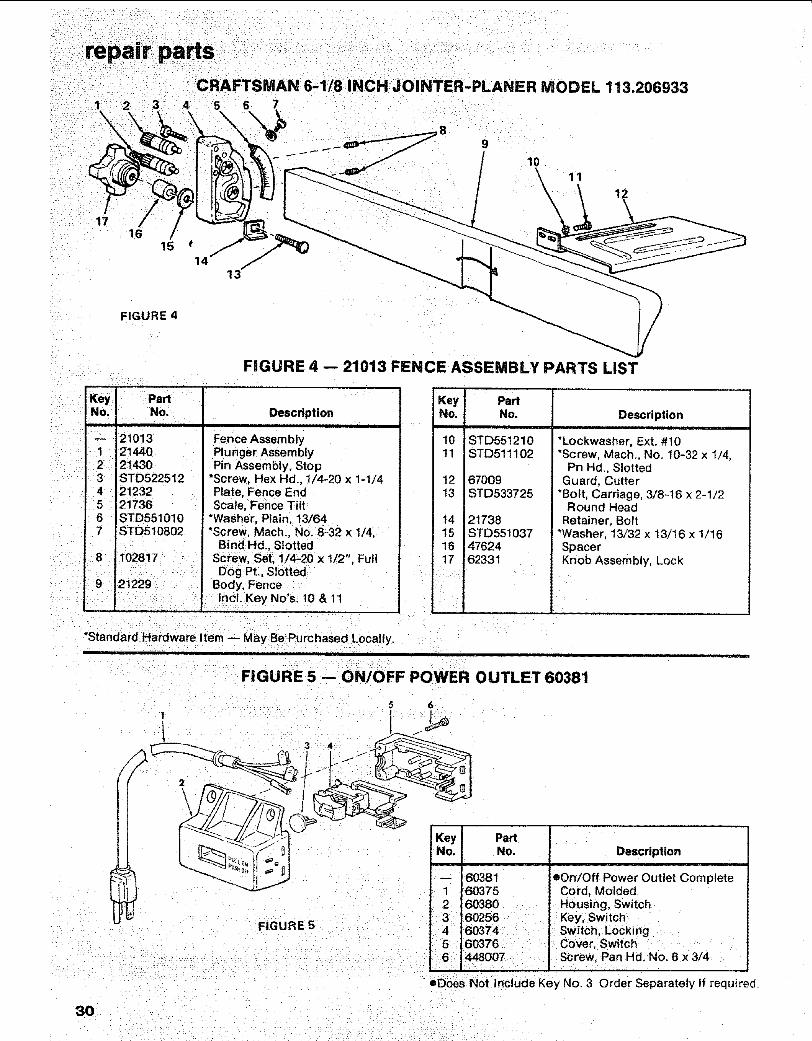
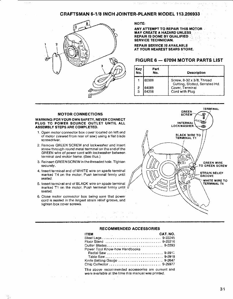
CRAFTSMAN 6-1/8 INCH JOINTER-PLANER MODEL 113.206933
/
5
FIGURE 2
FIGURE 2 -- LEGS PARTS LiST
KeyNo.
1234
56
78910
Part
No. Descriptionii
67033 Stiffener, End60314 • Screw, Truss Hd. 1/4-20 x 5/8STD551225 e*Lockwasher, 1/4 ExternalSTD541025 e'Nut, Hex 1/4-2067032 Stiffener, Side62614 Leg62204 • Clip, Cord67034 Support, MotorSTD541250 e'Nut, Hex Hd. 1/2-13803835 D Foot, Leveling67035 Bag of Loose Parts (Not Iltus.)
HARDWARE FOR MOUNTING TOOL AND MOTOR
-- STD532507 e'Bolt, Carriage 5/16-18 x 3/4STD551231 e*Lockwasher, 5/16 ExternalSTD551031 s'Washer, 1!/32 x 11/16 x 1/t6
- STD523120 t'Screw, Hex Hd= 5/16-16 x 2: e'Nut, Hex 5116-!8
oSupptied in Loose Parts Bag 67035
*Standard Hardware Item - May be Purchased Locally.
28
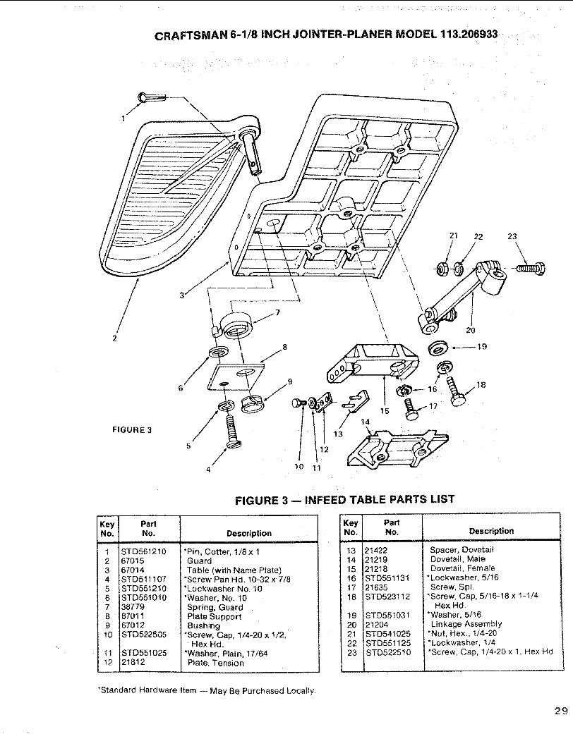
CRAFTSMAN 6-1/8 INCH JOINTER-PLANER MODEL 113.206933
1 \
/2
FIGURE 3
21 22
\\
\
\ 2o\
11
23
Key PartNo. No.
nl ,,i,n i ,n
1 STD5612102 670153 670144 STD5111075 STD5512t06 STD5510107 387798 670119 67012t0 STD522505
11 STD55tO2512 21812
FIGURE 3 -- INFEED TABLE PARTS LIST
Descriptioni inl
*Pin, Cotter, 1/8x 1Guard
Tabfe (with Name Plate)*Screw Pan Hd. 10-32 x 7/8*Lockwasher No. 10*Washer, No. 10Spring. GuardPlate SupportBushing
*Screw, Cap, 1/4-20 x !/2,Hex Hd.
*Washer, Plain, 17/64Plate, Tension=
Key PartNo. No.
13 2142214 2121915 2121816 STD55113117 i2163518 STD523112
1920212223
STD55103121204STD54!025STD551125STD5225t0
Description
Spacer, DovetailDovetail, MaleDovetail, Female
*Lockwasher, 5/16Screw, Spl.
*Screw, Cap, 5/16-18 x t_1/4Hex Hd.
*Washer, 5/I6Linkage Assembly
*Nut, Hex,, 1/4-20"Lockwasher, 1/4*Screw, Cap, 1/4-20 x 1, Hex Hd.
*Standard Hardware Item -- May Be Purchased Locally.
29
CRAFTSMAN 6-1/8 INCH JOINTER-PLANER MODEL 113.2069335 6 7
/17 /
1615
9
/ 10
\\
11
12
FIGURE 4
FIGURE 4 -- 21013 FENCE ASSEMBLY PARTS LIST
Key PartNo. I No.
210131 21440
2 21430STD52251221232
i 21736STD551010
7 STD510802r
8 102817
Descriptioni
9 21229i
nc KeyNo's 10&11I :,, . •
Plunger Assembly
.Pin Assembly, StopScrew, Hex Hd. 1/4-20 x !-t/4Plate, Fence EndScale, Fence Tilt
*Washer, Ptain, 13/64*Screw, Mach., No. 8-32 x 1/4,
Bind Hd., SlottedScrew, Se[, 1/4-20 x 1/2", FullDog Pt., Slotted
, Body, Fence
Key PartNo. No.
10 STD55121011 STD511102
12 6700913 STD533725
14 2173815 STD55103716 4762417 62331
Description,,, ,,,
*Lockwasher, Ext. #10*Screw, Mach,, No. 10-32 x t/4,
Pn Hd., SlottedGuard, Cutter
"Bolt, Carriage, 3/8-t6 x 2-1/2Round Head
Retainer, Bolt*Washer, 13/32 x 13/16 x !/16SpacerKnob Assembly, Lock
*Standard Hardware Item -- May BePurchased Locally.
FIGURE 5 -- ON/OFF POWER OUTLET 60381
FIGURE 5
6
Key PartNo. No.
-- 603811 603752 603803 602564
5
Description
cOn/Off Power Outlet CompleteCord, MoldedHousing, SwitchKey, Switch
60374 ' Switch, Locking60376 Cover Switch
6 448007 i Screw, PanHd, No.6x3/4
eDoes Not Include Key No. 3 Order Separately If required.
3O
CRAFTSMAN 6-1/8 iNCH JOINTER-PLANER MODEL 113.206933
NOTE:
ANY ATTEMPT TO REPAIR THIS MOTORMAY CREATE A HAZARD UNLESSREPAIR iS DONE BY QUALIFIEDSERVICE TECHNICIAN.
REPAIR SERVICE IS AVAILABLEAT YOUR NEAREST SEARS STORE,
FIGURE 6 -- 67094 MOTOR PARTS LIST
Key PartNo. No.
1 60306
2 640883 64258
Description
Screw, 8_32 x 3/8, ThreadCutting, Slotted, Serrated Hd.
Cover, TerminalCord with Plug
........ • ........................................................... , ,,,i,i,,
MOTOR CONNECTIONS
WARNING: FOR YOUR OWN SAFETY, NEVER CONNECTPLUG TO POWER SOURCE OUTLET UNTIL ALLASSEMBLY STEPS ARE COMPLETED.
1. Open motor connector box cover located on left endof motor (viewed from rear of saw) using a flat b_adescrewdriver,
2. Remove GREEN SCREW and Iockwasher and insertscrew through round metal terminal on the end of theGREEN wire of power cord with Iockwasher betweenterminal and motor frame. (See [llus_)
3. Reinsert GREEN SCREW in the threaded hole, Tightensecurely.
4. Insert terminal end of WHITE wire on spade terminalmarked T4 on the motor, Push terminal firmly untilseated.
5. Insert terminal end of BLACK wire on spade termina_marked T1 on the motor. Push terminal firmly untilseated.
6. Close motor connector box being sure that powercord is seated in the largest strain relief groove, andtighten box cover screws.
TERMINALGREEN
INTERNALLOCKWASHER
GREEN WtRE_TO GREEN SCREW
STRAIN RELIEF)VE
WHITE WIRE TOTERMINAL T4
IIIHI,, _ i H ........................... ii
RECOMMENDED ACCESSORIES
ITEM CAT. NO.Steel Legs ................................. 9-22245FloOr Stand .............................. 9-22216Cutter Blades .............................. 9-2293Power Too! Know-how Handbooks
Radial Saw .............................. 9-291;Table Saw ................................. 9o2918
Knife Setting Gauge ........................ 9-2647Chip Collector ............................ 9-29977
The above recommended accessories are current andwere available at the time this manual was printed_
31
SL _,AIR,,
SERVICE
MODEL NO.11 3.206933JOINTERiPLANER WITH
LEGS AND MOTOR
HOW TO ORDERREPAIR PARTS
Part No. 67096
6-1/8 iNCH JOINTER-PLANER
Now that you have purchased your jointer-planer, should aneed ever exist for repair parts or service, simply contactany Sears Service Center and most Sears, Roebuck and Co,stores. Be sure to provide all pertinent facts when you callor visit.
The model number of your 6-1/8 inch jointer-planer wil! befound on a plate attached to your base.
WHEN ORDERING REPAIR PARTS, ALWAYS GIVE THEFOLLOWING INFORMATION:
PART NUMBER PART DESCRIPTION
MODEL NUMBER NAME OF ITEM113.206933 6-1/8 INCH JOtNTER-PLANER
All parts listed may be ordered from any Sears ServiceCenter and most Sears stores. If the parts you need are notstocked locally, your order wilt be electronically transmittedto a Sears Repair Parts Distribution Center for handling.
Sold by SEARS, ROEBUCK AND CO., Chicago, IL. 60684 U.S.A.Form No. SP4939-1 Printed in U.S.A. 11/