Embed Size (px)
DESCRIPTION
1
Citation preview

1
CRACKS IN BUILDINGS
CAUSES AND PREVENTION
A SEMINAR
SUBMITTED BY
TARSEM LAL
UNIVERISTY ROLL NO.81402105009
IN PARTIAL FULFILLMENT FOR THE AWARD OF DEGREE
OF
MASTER OF TECHNOLOGY
IN
STRUCTURAL ENGINEERING
AT
PTU REGIONAL CENTRE
DAV INSTITUTE OF ENGINEERING & TECHNOLOGY
JALANDHAR
2010

2
CRACKS IN BUILDINGS
CAUSES AND PREVENTION
A SEMINAR
SUBMITTED BY
TARSEM LAL
UNIVERISTY ROLL NO.81402105009
IN PARTIAL FULFILLMENT FOR THE AWARD OF DEGREE
OF
MASTER OF TECHNOLOGY
IN
STRUCTURAL ENGINEERING
AT
PTU REGIONAL CENTRE
DAV INSTITUTE OF ENGINEERING & TECHNOLOGY
JALANDHAR
2010

3
DECLAREATION
I hereby declare that Seminar entitled “CRACKS IN BUILDINGS-
CAUSES AND PREVENTION” submitted for the M. Tech Degree is
my original work & the seminar has not formed the basis for
award of any degree, associate ship, fellowship or any other
similar title
PLACE: JALANDHAR TARSEM LAL
DATE: 20.11.2010 ROLL NO. 81402105009
DAVIET JALANDHAR

4
ACKNOWLEDGEMENT
I extend my deep sense of gratitude and indebtedness to my guide
Prof. Sanjeev Naval, Head, Department Of Civil Engineering, DAV Institute
of Engineering & Technology, Jalandhar, for his kind attitude, invaluable
guidance, keen interest, immense help, inspiration and encouragement
which helped me in carrying out my present work.
I am grateful to him for giving a lot of freedom, encouragement and
guidance, and the faculty members of Civil Engineering Department, DAV
Institute of Engineering & Technology, Jalandhar, for providing all kind of
possible help throughout for the completion of this seminar work...
I am also thankful to the Technical Laboratory Staff of DAV institute of
Engineering & Technology, Jalandhar for helping me during the experimental
work. It is a great pleasure for me to acknowledge and express my gratitude
to my classmates and friends for their understanding, unstinted support.
Lastly, I thank all those who are involved directly or indirectly in completion
of the present seminar work.
TARSEM LAL
ROLL NO: 81402105009

5
ABSTRACT
Cracking in structures is of common occurrence and engineers are
often required to look into their causes and to carry out suitable repairs and
remedial measures. For repairs and remedies to be effective, it is essential
that the engineer should have proper understanding of various causes of
cracking. For investigating the causes it is necessary to observe carefully
location, shape, size, depth, behavior and other characteristics of the cracks,
and to collect information about specifications of the job, time of
construction and past history of the structure. It will also be necessary for
the engineer to know as to when the cracks first came to notice and whether
the cracks are structural or non-structural.
Structural cracks are those which are due to incorrect design, faulty
construction or overloading and these may endanger the safety of a building.
Non-structural cracks which are due to moisture changes, thermal
variations, elastic deformation, creep, chemical reaction, foundation
movement and settlement of soil, vegetation, etc. Non-structural cracks are
mostly due to internally induced stresses in building materials and these
generally do not directly result in structural weakening. In course of time
however, sometimes these cracks may, because of penetration of moisture
through cracks or weathering action, result in corrosion of reinforcement and
thus may render the structure unsafe.
In order to be able to prevent or to minimize occurrence of
cracks, it is necessary to understand basic causes of cracking and to
have knowledge about certain properties of building materials,
specification for mortar and concrete, Architectural design of
building, structural design, foundation design, construction practices
& techniques and environments.

6
Contents CHAPTER 1 .............................................................. 9
INTRODUCTION ......................................................................................... 9
CHAPTER 2 ............................................................ 12
LITERATURE SURVEY ................................................................................ 12
2.1 MOISTURE CHANGES ......................................................................... 12
2.3 THERMAL VARIATIONS ....................................................................... 20
2.4 ELASTIC DEFORMATION ..................................................................... 26
2.4 MOVEMENT DUE TO CREEP ................................................................. 27
2.5 MOVEMENT DUE TO CHEMICAL REACTION ............................................ 29
2.6 FOUNDATION MOVEMENT AND SETTLEMENT OF SOIL ............................. 32
2.8 CRACKING DUE TO VEGETATION ......................................................... 34
CHAPTER 3 ............................................................ 35
THE CASE STUDY ..................................................................................... 35
3.1 BACKGROUND ................................................................................... 35
3.2 INVESTIGATION ................................................................................ 37
3.3 REPAIR PROPOSALS ........................................................................... 41
3.4 REPAIR WORK ................................................................................... 42
3.5 REPAIR WORK EVALUATION ................................................................ 43
CONCLUSION .......................................................................................... 46
REFERENCE ............................................................................................. 49
7
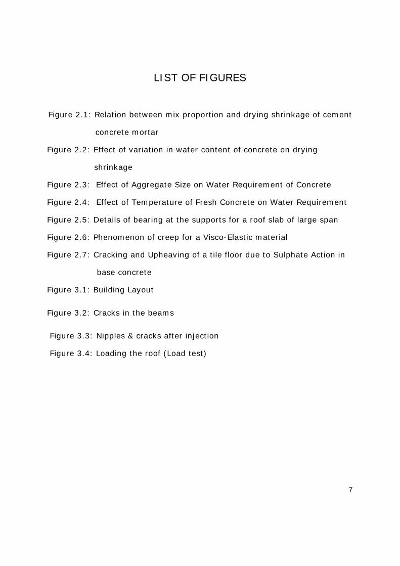
LIST OF FIGURES
Figure 2.1: Relation between mix proportion and drying shrinkage of cement
concrete mortar
Figure 2.2: Effect of variation in water content of concrete on drying
shrinkage
Figure 2.3: Effect of Aggregate Size on Water Requirement of Concrete
Figure 2.4: Effect of Temperature of Fresh Concrete on Water Requirement
Figure 2.5: Details of bearing at the supports for a roof slab of large span
Figure 2.6: Phenomenon of creep for a Visco-Elastic material
Figure 2.7: Cracking and Upheaving of a tile floor due to Sulphate Action in
base concrete
Figure 3.1: Building Layout
Figure 3.2: Cracks in the beams
Figure 3.3: Nipples & cracks after injection
Figure 3.4: Loading the roof (Load test)

8
LIST OF TABLES
TABLE 1: MOISTURE MOVEMENT OF SOME COMMON BUILDING MATERIALS
TABLE 1: GENERAL PRECAUTIONS FOR AVOIDANCE OF SHRINKAGE CRACKS
IN THE USE OF SOME COMMON BUILDING MATERIALS
TABLE 1: COEFFICIENT OF THERMAL EXPANSION OF SOME COMMON
BUILDING MATERIALS (WITHIN THE RANGE 0°C to 100° C)
TABLE 1: HEAT REFLECTIVITY COEFFICIENT OF SOME COMMON BUILDING
MATERIALS
TABLE 1: A GENERAL GUIDE FOR PROVISION OF MOVEMENT JOINTS
IN BUILDINGS

9
CHAPTER 1
INTRODUCTION Modern structures are comparatively tall and slender, have thin walls,
are designed for higher stresses and are built at a fast pace. These
structures are, therefore, more crack-prone as compared with old structures
which used to be low, had thick walls, were lightly stressed and were
built at a slow pace. Moreover, moisture from rain can easily reach the inside
and spoil the finish of a modern building which has thin walls. Thus
measures for control of cracks in buildings have assumed much greater
importance on account of the present trends in construction.
Cracks in buildings are of common occurrence. A building
component develops cracks whenever stress in the component
exceeds its strength. Stress in a building component could be caused
by externally applied forces, such as dead, live, wind or seismic
loads, or foundation settlement or it could be induced internally due
to thermal variations, moisture changes, chemical action, etc.
Cracks could be broadly classified as structural or non-structural.
Structural cracks are those which are due to incorrect design, faulty
construction or overloading and these may endanger the safety of a
building. Extensive cracking of an RCC beam is an instance of structural
cracking. Non-structural cracks are mostly due to internally induced stresses
in building materials and these generally do not directly result in
structural weakening. In course of time, however, sometime non-
structural cracks may, because of penetration of moisture through
cracks or weathering action, result in corrosion of reinforcement and thus
may render the structure unsafe. Vertical cracks in a long compound wall
due to shrinkage or thermal variation is an instance of non-structural
10
cracking. Non-structural cracks, normally do not endanger the safety of a
building, but may look unsightly, or may create an impression of faulty work
or may give a feeling of instability.
Cracks may appreciably vary in width from very thin hair cracks barely
visible to naked eye (about 0.01 mm in width) to gaping cracks 5 mm or
more in width. A commonly known classification1 of cracks, based on their
width is: (a) thin— less than 1 mm in width, (b) medium — 1 to 2 mm in
width, and (c) wide — more than 2 mm in width. Cracks may be of uniform
width throughout or may be narrow at one end, gradually widening at the
other. Cracks may be straight, toothed, stepped, map pattern or random
and may be vertical, horizontal or diagonal. Cracks may be only at the
surface or may extend to more than one layer of materials. Occurrence of
closely spaced fine cracks at surface of a material is sometimes called
'crazing'.
Internally induced stresses in building components lead to dimensional
changes and whenever there is a restraint to movement as is generally the
case, cracking occurs. Due to dimensional changes caused by moisture or
heat, building components tend to move away from stiff portions of the
building which act as fixed points. In case of symmetrical structures,
the centre of the structure acts as a fixed point and movement takes place
away from the centre. A building as a whole- can easily move in the vertical
direction, but in the horizontal direction, sub-structure and foundation
exert a restraining action on the movement of the superstructure.
Thus, vertical cracks occur in walls more frequently due to horizontal
movement. Volume changes due to chemical action within a component
result in either expansion or contraction and as a result cracks occur in the
components.

11
Internal stresses in building components could be compressive, tensile
or shear. Most of the building materials that are subject to cracking, namely,
masonry, concrete, mortar, etc, are weak in tension and shear and thus
forces of even small magnitude, when they cause tension or shear in a
number, are able to cause cracking. It is possible to distinguish between
tensile and shear cracks by closely examining their physical characteristics.
Depending on certain properties of building materials, shrinkage
cracks may be wider but further apart, or may be thin but more closely
spaced. As a general rule, thin cracks, even though closely spaced
and greater in number, are less damaging to the structure and are not so
objectionable from aesthetic and other considerations as a fewer number of
wide cracks.

12
CHAPTER 2
LITERATURE SURVEY In order to be able to prevent or to minimize occurrence of cracks, it is
necessary to understand basic causes of cracking and to have knowledge
about certain properties of building materials. Principal causes of occurrence
of cracks in buildings are as follows:
a) Moisture changes,
b) Thermal variations,
c) Elastic deformation,
d) Creep,
e) Chemical reaction,
f) Foundation movement and settlement of soil, and
g) Vegetation.
2.1 MOISTURE CHANGES
As a general rule, most of the building materials having pores in their
mortar, burnt clay bricks, some stones, timber, etc. Expand on
absorbing moisture and shrink on drying. These movements are
reversible, that is Cyclic in nature and is caused by increase or decrease in
the inter-pore pressure with moisture changes, extent of movement
depending on molecular structure and porosity of a material.
Reversible Movement
From consideration of moisture movement of reversible nature,
materials could be broadly classified as under:

13
a) Materials having very small moisture movement, as for example,
burnt clay bricks, igneous rocks, limestone, marble, gypsum plaster, metals,
etc. The use of these materials does not call for many precautions.
b) Materials having small to moderate moisture movement, as
for example, concrete, sand-lime bricks, sandstones, cement and lime
mortars, etc. In the use of these materials some precautions in design and
construction are necessary.
Based on research, range of reversible moisture movement of some of
the commonly used building materials is given in Table 1.
TABLE 1 MOISTURE MOVEMENT OF SOME COMMON BUILDING MATERIALS
S
No.
Material Moisture Movement (Dry to saturation
percent)
(1) (2) (3)
i) Burnt clay bricks, limestone 0.002 to 0.01
ii) Hollow clay bricks, terra cota 0.006 to 0.016
iii) Expanded clay concrete, cinder concrete 0.017 to 0.04
IV) Sandstone, sand-lime bricks, concrete
block's
0.01 to 0.05
v) Foam cellular concrete 0.04 to 0.05
VI) Cast-stone, dense concrete, cement
lime mortars
0.02 to 0.06
vii) Auto-clayed aerated concrete, clinker
concrete
0.03 to 0.08
viii) Marble Negligible
ix) Wood along grain 0.000 8
x) Wood across grain — tangential 5 to 15
xi) Wood across grain —radial 3 to 5

14
Initial drying shrinkage in cement and lime a product which is partly
irreversible is 50 percent more than the values of reversible shrinkage
given above 17. Data for items (i) to (vii) are reproduced from
'Principles of modern buildings'. Volume I and for items (viii) to (xi)
from 'Common defects in buildings 11.
INITIAL SHRINKAGE
Initial shrinkage, which is partly irreversible, normally
occurs in all building materials or components that are cement/lime-
based, for example, concrete, mortar, masonry units, masonry and
plasters. This shrinkage is one of the main causes of cracking in
structures. Influence of these factors on shrinkage is as follows:
a) Cement content —as a general rule, richer the mix, greater the drying
shrinkage. Conversely, larger the volume of aggregate in concrete, lesser
the shrinkage. For the range of aggregate content generally used for
structural concretes, increasing the volume of aggregates by 10 percent can
be expected to reduce shrinkage by about 50 percent 8. Relation between
mix proportion and shrinkage is depicted in Fig.2.1.
(Reproduced from ‘Principles of Modern Buildings Volume 17)
Figure 2.1: Relation between mix proportion and drying shrinkage of cement
concrete mortar

15
b) Water content — Greater the quantity of water used in the mix, greater
the shrinkage. Thus a wet mix has more shrinkage than a dry mix which is
otherwise similar. That explains why a vibrated concrete, which has low
slump, has lesser shrinkage than a manually compacted concrete, which
needs to have greater slump. In terrazo and concrete floors, use of excess
water in the mix (commonly resorted to by masons to save time and lab our
on compaction and screeding) is one of the principal causes of cracking in
such floors. A typical relation between water content and drying shrinkage is
shown in Fig. 2.2.3
(Based on graph given in ‘Control of Cracking in Concrete Structures 3)
Figure 2.2: Effect of variation in water content of concrete on drying shrinkage
c) Aggregates — By using the largest possible maximum size of aggregate in
concrete and ensuring good grading, requirement of water for concrete of
desired workability is reduced and the concrete thus obtained has less
shrinkage because of reduction in the porosity of hardened concrete. Any
water in concrete mix in excess of that required for hydration of cement, to
give the desired workability to the mix, results in formation of pores when it
dries out, thus causing shrinkage. Figure 2.3 illustrates the effect of

16
aggregate size on water requirement 5. For the same cement-aggregate
ratio, shrinkage of sand mortars is 2 to 3 times that of concrete using 20
mm maximum size aggregate and 3 to 4 times that of concrete using 40 mm
maximum size aggregate 8.
Figure 2.3: Effect of Aggregate Size on Water Requirement of Concrete
d) Use of accelerators — Use of calcium Chloride as accelerator in
concrete appreciably shrinkage increases—being up to 50 percent with 0.5 to
2.0 percent addition of calcium chloride. Shrinkage could be much more if
proportion of calcium chloride is higher 20. Moreover, it has some corrosive
effect on reinforcement in concrete.
e) Curing—Curing also plays an important part in limiting shrinkage. If
proper curing is started as soon as initial set has taken place and it is
continued for at least 7 to 10 days, drying shrinkage is comparatively less,
because when hardening of concrete takes place under moist environments,
there is initially some expansion which offsets a part of subsequent
shrinkage. Steam curing of concrete blocks at the time of manufacture
reduces their liability to shrinkage as high temperature results in
precarbonation 6.
f) Presence of excessive fines—Presence of excessive fines—silt, clay,
dust —in aggregates has considerable effect on extent of shrinkage in

17
concrete. Presence of fines increases specific surface area of aggregates and
consequently the water requirement. Rightly, therefore, specifications
for fine and coarse aggregates for concrete lay much emphasis on
cleanliness of aggregates and stipulate a limit for the maximum percentage
of fines in aggregates which is 3 percent for coarse as well as uncrushed
fine aggregate according to IS: 383-1970 7.
g) Humidity — Extent of shrinkage also, depends on relative humidity
of ambient air. Thus, shrinkage is much less in coastal areas where relative
humidity remains high throughout the year. Low relative humidity may also
cause plastic shrinkage in concrete.
h) Composition of cement — Chemical composition of cement used for
concrete and mortar also has some effect on shrinkage. It is less for
cements having greater proportion of tricalcium silicate and lower proportion
of alkalis like sodium and potassium oxides. Rapid hardening cement has
greater shrinkage than ordinary Portland cement.
j) Temperature — an important factor which influences the water
requirement of concrete and thus its shrinkage is the temperature of fresh
concrete. This is illustrated in Fig.2.4 based on studies made by Bureau of
Reclamation, USA 3.

18
Figure 2.4: Effect of Temperature of Fresh Concrete on Water Requirement
If temperature of concrete gets lowered from 38°C to 10°C it would result in
reduction of water requirement to the extent of about 25 liters per cubic
meter of concrete for the same slump. It, thus, follows that in a tropical
country like India, concrete work done in mild winter.
CRACKS IN FRESHLY LAID CEMENT CONCRETE
In freshly laid cement concrete pavements and slabs, sometimes
cracks occur before concrete has set due to plastic shrinkage. This
happens if concrete surface loses water faster than bleeding action brings it
to top of concrete at the surface results in shrinkage and as concrete in
plastic state cannot resist any tension; short cracks develop in the material.
These cracks may be 5 to 10 cm in depth and their width could be as much
as 3 mm. Once formed these cracks stay and may, apart from being
unsightly affect serviceability of the job. In order, to prevent plastic
shrinkage of concrete, it is necessary to take steps so as to slow down the
rate of evaporation from the surface of freshly laid concrete. Immediately
after placing of concrete, solid particles of the ingredients of concrete begin
to settle down by gravity action and water rises to the surface. This process
— known as bleeding—produces a layer of water at the surface and
continues till concrete has set. As long as rate of evaporation is lower than
the rate of bleeding, there is a continuous layer of water at the surface, as
evidenced by the appearance of ‘water sheen' on the surface and shrinkage
does not occur.
CRACKS IN BRICK WORK DUE TO EXPANTION
When clay bricks (or other clay products) are fired, because
of high temperature (900°C to 1000°C), not only intermolecular water but
also water that forms a part of the molecular structure of clay, is driven out.

19
After burning, as the temperature of bricks falls down, the moisture-
hungry bricks start absorbing moisture from the environment and
undergo gradual expansion, bulk of this expansion being irreversible.
Extent of irreversible expansion depends on the nature of soil, that is,
its chemical and minerological composition and the maximum
temperature of burning. When bricks are fired at very high temperature,
as in the case of engineering bricks, because of fusion of soil particles,
there is discontinuity in the pores and as a result, water absorption
and moisture movements are less.
MEASURES FOR CONTROLLING CRACKS DUE TO SHRINKAGE
(i) To avoid cracks in brickwork on account of initial expansion,
a minimum period varying from 1 week to 2 weeks is recommended by
authorities for storage of bricks after these are removed from Kilns 11.
(ii) Shrinkage cracks in masonry could be minimized by avoiding use of
rich cement mortar in masonry and by delaying plaster work till masonry has
dried after proper curing and has undergone most of its initial shrinkage.
(iii) Use of precast tiles in case of terrazo flooring is an example of this
measure. In case of in-situ/terrazo flooring, cracks are controlled by laying
the floor in small alternate panels or by introducing strips of glass, aluminum
or some plastic material at close intervals in a grid pattern, so as to render
the shrinkage cracks imperceptibly small.
(iv) In case of structural concrete, shrinkage cracks are controlled by
use of reinforcement, commonly termed as 'temperature reinforcement'.
This reinforcement is intended to control shrinkage as well as temperature
effect in concrete and is more effective if bars are small in diameter and are
thus closely spaced, so that, only thin cracks which are less perceptible,
occur 6.

20
(v) To minimize shrinkage cracks in rendering/plastering, mortar for
plaster should not be richer than what is necessary from consideration of
resistance to abrasion and durability
2.3 THERMAL VARIATIONS
It is a well known phenomenon of science that all materials, more or
less, expand on heating and contract on cooling. Magnitude of movement,
however, varies for different materials depending on their molecular
structure and other properties. When there is some restraint to movement of
a component of a structure, internal stresses are set up in the component,
resulting in cracks due to tensile or shear stresses. Extent of thermal
movement in a component depends on a number of factors, such as
temperature variation, dimensions, co-efficient of expansion and some other
physical properties of the materials.
• Thermal co-efficient for brickwork as given above is for
movement in horizontal direction; for movement of brickwork in
the vertical direction, coefficient is 50 percent higher 18.
• Data contained in this table is from 'Principles of modern
buildings'. Vol. I1 excepting item (iii), which is from the
'Performance of high" rise masonry structures 18 and item (vi)
which is from ' Thermal movements and expansion joints in
buildings 17 .
Coefficients of Thermal expansion of some of the common building
materials are given in Table 3.

21
TABLE 3 COEFFICIENT OF THERMAL EXPANSION OF SOME COMMON BUILDING MATERIALS (WITHIN
THE RANGE 0°C to I00°C)
Sr.No
MATERIAL Co-EFFICENT OF THEMAL EXPANSION
(1) (2) (3)
i) Bricks and brickwork 5 to 7
ii) Cement mortar and 10 to 14
concrete
iii) Sand-lime bricks 11 to 14
iv) Stones:
a) Igneous rocks 8 to10
(granite, etc)
b) Limestone’s 2.4 to 9
c) Marble 1.4 to 1 1
d) Sandstones 7 to 16
e) Slates 6 to 10
v) Metals:
a) Aluminum 25
b) Bronze 17.6
c) Copper 17.3
d) Lead 29
e) Steel and iron 11 to 13
VI) Wood

22
FACTORS EFFECT THE THERMAL MOVEMENT
Other factors which influence the thermal movement of component
are: colour and surface characteristics, thermal conductivity, provision of an
insulating or protective layer and internally generated heat, as discussed
below:
a) Colour and Surface Characteristics
Dark coloured and rough textured materials have lower reflectivity
than light coloured and smooth textured materials and thus, for the same
exposure conditions, gain of heat and consequently rise in temperature of
the former is more.
b) Thermal Conductivity
Low thermal conductivity of a component, which is subject to solar
radiation, produces a thermal gradient in the component, resulting in
warping of the component. In case of concrete roof slabs, as the
material has low conductivity, thermal gradient is quite appreciable and that
causes the slab to arch up and also to move outward due to heat from the
sun. This results in cracks in external walls which support the slab and in the
internal walls that are built up to the soffit of the slab. It is thus very
necessary to provide a layer of adequate thickness of a suitable material
preferably with a good reflective surface over concrete roof slab in order to
minimize cracking in walls.
c) Provision of an Insulating or Protective Layer
If there is a layer of an insulating or heat absorbing material acting
as protective cover to a, component, shielding it from sun rays, heat gain
or loss of the component is considerably reduced and thus its thermal
movement is lessened.

23
d) Internally Generated Heat
Rise of temperature in fresh concrete can take place not only due to
heat gained from an external source but also due to heat generated within
the material by hydration of cement. Reflectivity co-efficient of some of
the commonly used building materials are given in Table 4.
TABLE 4 HEAT REFLECTIVITY CO-EFFICIENT OF SOME COMMON BUILDING
MATERIALS
Sr.
No
Material Reflectivity Co-efficient
(1) (2) (3)
i) Asphalt 0.09 to. 17
ii) G.I. sheets 0.10 to 0.36
iii) Asbestos cement sheets 0.29 to 0.58
iv) Brickwork (exposed) 0.30 to 0.58
v) Cement mortar and
concrete
0.34 to 0.65
vi) Granite (reddish) 0.45
Vii) Aluminum paint 0.46
viii) Aluminum sheets 0.47
ix) Marble (white) 0.56
x) White paint 0.71
xi) Whitewash 0.79 to 0.91

24
MEASURES FOR CONTROLLING CRACKS DUE TO SHRINKAGE
Some general measures for prevention of cracks due to thermal
movement are given below:
a) Wherever feasible, provision should be made in the design and
construction of structures for unrestrained movement of parts, by
introducing movement joints of various types, namely, expansion joints,
control joints and slip joints.
b) Even when joints for movement are provided in various parts of a
structure, some amount of restraint to movement due to bond, friction and
shear is unavoidable. Concrete, being strong in compression, can stand
expansion but, being weak in tension, it tends to develop cracks due to
contraction and shrinkage, unless it is provided with adequate reinforcement
for this purpose. . Members in question could thus develop cracks on
account of contraction and shrinkage in the latter direction. It is, therefore,
necessary to provide some reinforcement called 'temperature reinforcement"
in that direction.
c) Over flat roof slabs, a layer of some insulating material or some other
material having good heat insulation capacity, preferably along with a high
reflectivity finish, should be provided so as to reduce heat load on the roof
slab.
d) In case of massive concrete structures, rise in temperature due to heat of
hydration of cement should be controlled.
PROVISION OF JOINTS IN STRUCTURE
Movement joints in structures are introduced so that unduly high
stresses are not set up in any part of a structure, and it may not develop
unsightly cracks. When a joint permits expansion as well as contraction it is

25
termed as 'expansion joint 5 , when it allows only contraction, it is termed as
'control joint' and when the joint permits sliding movement of one
component over another it is termed as 'slip joint’. Information given in
Table 5 is intended to serve as a general guide in this regard.
TABLE 5: A GENERAL GUIDE FOR PROVISION OF MOVEMENT JOINTS INBUILDINGS
Type of Structure Movement of Joints
1. RCC roof slab Provide 20 to 25 mm wide, joint at 10 to 20 M apart
2. Supports for RCC slabs 4
to 6m length
Provide slip joint between slab and bearing wall.
3. RCC framed and bearing
structure
Provide 25 to40mm wide expansion joints at 30 to 45 M interval
4. Junction between old and
new structure
Provide vertical slip joints
5. Compound walls Expansion joint 5 to 8 mm at 5 to 8 M interval and change of
direction
6. Concrete pavement Provide 20 to 25 mm wide joints at 25 m to 40 m interval with
control joints at 5 to 8 m. In cross direction control joints have to
be provided at 3 to 5 m intervals.
7. Chajja Provide expansion joint 5 to 8 mm wide at 4 to 6 M interval.
8. RCC Railing Provide expansion joints 5 to 8 mm wide at 6 to 9 m interval.
Note — For seismic Zones III, IV & V, expansion joints have to be
much wider for which IS: 4326-1976 'Code of practice for
earthquake resistant design and construction of buildings (first
revision) should be referred 19 .

26
2.4 ELASTIC DEFORMATION
Structural components of a building such as walls, columns, beams
and slabs, generally consisting of materials like masonry, concrete, steel,
etc, undergo elastic deformation due to load in accordance with Hook's law,
the amount of deformation depending upon elastic modulus of the material,
magnitude of loading and dimensions of the components. This deformation,
under circumstances such as those mentioned below, causes cracking in
some portions:
a) When walls are unevenly loaded with wide variations in stress in different
parts, excessive shear strain is developed which causes cracking in walls.
b) When a beam or slab of large span undergoes excessive deflection and
there is not much vertical load above the supports, ends of beam/slab curl
up causing cracks in supporting masonry.
Figure 2.5: Details of bearing at the supports for a roof slab of large span

27
c) When two materials, having widely different elastic properties, are
built side by side, under the effect of load, shear stress is set up at the
interface of the two materials, resulting in- cracks at the junction.
Sahlin26 has recommended use of cellular plastic pad with a layer of
tar-felt under the slab bearing together with a filling of mineral wool
between the slab and brick cover in the upper-most one or two storey’s of a
multistoried building having large spans so as to avoid cracks at supports
due to deflection, and shrinkage of slab as shown in figure 2.21.
2.4 MOVEMENT DUE TO CREEP
Some building items, such as concrete, brickwork and timber, when
subjected to sustained loads not only undergo instantaneous elastic
deformation, but also exhibit a gradual and slow time-dependent
deformation known as creep or plastic strain. The latter is made up of
delayed elastic strain which recovers when load is removed, and viscous
strain which appears as permanent set and remains after removal of load.
This phenomenon known as creep is explained in Fig. 2.18.
Figure 2.6: Phenomenon of creep for a Visco-Elastic material

28
BENEFICIAL EFFECT OF CREEP
In certain situations, creep has a beneficial effect on the
performance of materials, as it tends to relieve shrinkage and thermal
stresses. For example, seasonal variations in temperature being gradual
and slow, have less damaging effect on a structure because of creep in the
material. Similarly, if process of curing of concrete and masonry is
discontinued gradually, thereby slowing down the pace of drying of
these items, shrinkage stress gets relieved due to creep, and cracking due to
shrinkage is lessened.
MEASURES FOR PREVENTION OF CRACKS DUE TO CREEP
Though it may not be possible to eliminate cracking altogether,
following measures will considerably help in minimization of cracks due to
elastic strain, creep and shrinkage:
1) Use concrete which has low shrinkage and low slump.
2) Do not adopt a very fast pace of construction.
3) Do not provide brickwork over a flexural RCC member (beam or
slab) before removal of centering, and allow a time interval of at least 2
weeks between removal of centering and construction of partition or
panel wall over it.
4) When brick masonry is to be laid abutting an RCC column, defer
brickwork as much as possible.
5) When RCC and brickwork occur in combination and are to be plastered
over, allow sufficient time (at least one month) to RCC and- brickwork to
undergo initial shrinkage and creep before taking up plaster work. Also,
either provide a groove in the plaster at the junction or fix a 10 cm wide

29
strip of metal mesh or lathing over the junction to act as
reinforcement for the plaster.
6) In case of RCC members which are liable to deflect appreciably under
load, for example, cantilevered beams and slabs, removal of centering and
imposition of load should be deferred as much as possible (at least one
month) so that concrete attains-sufficient strength, before it bears the
load.
2.5 MOVEMENT DUE TO CHEMICAL REACTION
Certain chemical reactions in building materials result in
appreciable increase in volume of materials, and internal stresses are set up
which may result in outward thrust and formation of cracks. The materials
involved in reaction also get- weakened in strength. Commonly occurring
instances of this phenomenon are: sulphate attack on cement products,
carbonation in cement-based materials, and corrosion of reinforcement in
concrete and brickwork, and alkali-aggregate reaction.
EFFECT OF CHEMICAL REACTION
a)Due to Sulphate Attack
Soluble sulphate which are sometimes present in soil, ground water or
clay bricks react with tricalcium aluminate content of cement and hydraulic
lime in the presence of moisture and form products which occupy much
bigger volume than that of the original constituents. This expansive reaction
results in weakening of masonry, concrete and plaster and formation
of cracks. For such a reaction to take place, it is necessary that soluble
sulphates, tricalcium aluminate and moisture — all the three are present.
Severity of sulphate attack in any situation depends upon:

30
a) amount of soluble sulphates present;
b) permeability of concrete and mortar;
c) proportion of tri-calcium aluminate present in the cement used in
concrete and mortar; and
Sulphate attack on concrete and mortar of masonry in foundation and
plinth would result in weakening of these components and May, in course of
time, result in unequal settlement of foundation and cracks in the
superstructure. If brick aggregate used in base concrete of flooring contains
too much of soluble sulphates (more than 1 percent) and water table is
high so as to cause long spells of dampness in the base concrete, the latter
will in course of time swell up resulting in upheaving and cracking
of the concrete floor 15.
Figure 2.7: Cracking and Upheaving of a tile floor due to Sulphate Action in base
concrete

31
Upheaving of a concrete tile floor due to sulphate attack is shown in
Figure 2.7.
General Measures for Avoidance of Sulphate Attack:
a) In case of structural concrete in foundation, if sulphate content
in soil exceeds 0.2 percent or in ground water exceeds 300 ppm, use very
dense concrete and either increase richness of mix to 1:1/5:3 or use
sulphate resisting Portland cement/super-sulphated cement or adopt a
combination of the two methods depending upon the sulphate content of
the soil.
b) For superstructure masonry, avoid use of bricks containing too much of
soluble sulphates (more than 1 percent in exposed situations, such as
parapets, free standing walls and masonry in contact with damp soil as in
foundation and retaining walls; and more than 3 percent in case of walls in
less exposed locations) and if use of such bricks cannot be avoided, use rich
cement mortar (1:1/2:4.5 or 1:1/4 :3) for masonry as well as plaster or use
special cements mentioned earlier and take all possible precautions to
prevent dampness in masonry.
b)Due to Corrosion of Reinforcement
Under most conditions concrete provides good protection to
steel embedded in it. Protective value of concrete depends upon high
alkalinity and relatively high electrical resistivity of concrete, extent of
protection, depending upon the quality of concrete, depth of concrete cover
and workmanship.
As steel gets corroded, it increases in volume thus setting up internal
stress in concrete. In course of time it first causes cracks in line with
the direction of reinforcement and later causes spalling of concrete,

32
dislodging cover of reinforcement from the body of the concrete, thus
seriously damaging the structure.
To prevent such cracking and premature deterioration, it is desirable
to specify concrete of richer mix (say 1:1/5:3) for thin sections in exposed
locations and to take special care about grading, slump, compaction and
curing of concrete 6.
Figure 2.7: Cracking due to corrosion of reinforcement
2.6 FOUNDATION MOVEMENT AND SETTLEMENT OF SOIL
Shear cracks in buildings occur when there is large differential
settlement of foundation either due to unequal bearing pressure under
different parts of the structure or due to bearing pressure on soil being in
excess of safe bearing strength of the soil or due to low factor of safety in
the design of foundation.

33
EFFECT OF EXPANSIVE SOIL ON BUILDING
Buildings constructed on shrinkable clays (also sometimes called
expansive soils) which swell on absorbing moisture and shrink or drying as
a result of change in moisture content of the soil, are extremely crack
prone and special measures are necessary to prevent cracks in such
cases. Effect of moisture variation generally extends up to about 3.5 m
depth from the surface and below that depth it becomes negligible. Roots of
fast growing trees, however, cause drying and shrinkage of soil to greater
depth . Effect of soil movement can be avoided or considerably reduced by
taking the foundation 3.5 m deep and using moorum, granular soil or quarry
spoil for filling in foundation trenches and in plinth. Variation in moisture
content of soil under the foundation of a building could be
considerably reduced by providing a waterproof apron all round the
building. Use of under-reamed piles in foundation for construction on
shrinkable soils has proved effective and economical for avoiding cracks
and other foundation problems. It is necessary that bulb of the pile is
taken to a depth which is not much affected by moisture variations 22.
PROVISION OF HORIZONTAL EXTENTION WITH AN EXPENTION
JOINT
Sometimes it becomes necessary to make a horizontal extension
to an existing structure. Since foundation of a building generally
undergoes some settlement as load comes on the foundation, it is necessary
to ensure that new construction is not bonded with the old construction and
the two parts (old and new) are separated by a slip or expansion joints right
from bottom to the top, as otherwise when the newly constructed portion
undergoes settlement, an unsightly crack may occur at the junction. Care
should also be taken that in the vicinity of the old building; no excavation
below the foundation level of that building is made. When plastering the new

34
work a deep groove should be formed separating the new work from the old.
If the existing structure is quite long (20 to 25 m), the old and new work
should be separated by an expansion joint with a gap of about 25 to 40 mm
so as to allow some room for unhindered expansion of the two portions of
the building.
2.8 CRACKING DUE TO VEGETATION
Existence of vegetation, such as fast growing trees in the vicinity of
compound walls can sometimes cause cracks in walls due to expansive
action of roots growing under the foundation. Roots of a tree generally
spread horizontally on all sides to the extent of height of the tree above the
ground and when trees are located close to a wall; these should always be
viewed with suspicion.
Figure 2.7: Cracking of a compound wall due to growing roots under the
foundation

35
CHAPTER 3
THE CASE STUDY
A case study for causes of cracks and the repair of the main roofing
beams of Hall concrete slab will be presented. This chapter includes the
following:
1- Background
2- Investigation
3- Repair proposals
4- Repair work
5- Evaluation of the repair work
3.1 BACKGROUND
The afflicted structure forms part of the Gram Shabha Hall at Lohian.
The building was designed for 500 persons. The building is one story and
it consists of Main Hall with area 20x 30m, kitchen, store , and rooms for
persons. Figure 3.1 shows the layout of the building.
The building was under construction and the work was reached the
finishing stage. Attention was drawn towards the main beams in the Hall
where structural distress in the form of flexural and shear cracking had
been observed. Cracking was first noticed in August and by September; it
had progressed to the extent that the client requested immediate action
by the contractor. Figure 3.2: shows the cracks in the beams.

36
Figure 3.1: Building Layout

37
3.2 INVESTIGATION
An investigation process was carried out in order to determine the
causes of cracks. The investigation process basically consists of reviewing
technical information, condition survey of the site for visual inspection,
specific field tests to check for strength, reinforcement details, etc. The
investigation process carried out in order to determine the causes of
cracks of Hall’s beams was included the following phases:
Visual Inspection
The first signs of deterioration in concrete buildings are usually fine
cracks and rust stains which may be accompanied by spalling of concrete.
Visual Inspection is the first step to be taken in order to prepare a
complete investigation to determine the cause, nature and extent of
deterioration. Based on the visual inspection for the main beams of the
Hall, it was observed the following:

38
Figure 3.2: Cracks in the beams
• Cracking of all 12m and 16m span T-beams running along the
length of the building has been observed in the roof slab.
• The cracking follows patterns characteristically associated with
flexural and shear failure.
• Flexural cracking was spaced at about 200mm intervals along the
span and had extended 600mm up the web of the section.
• Diagonal shear cracking was found to be approximately 600mm in
length initiated at approximately 0.5 meter from the support.
• Cracks vary in size, from fine cracks (<0.3mm) to large (<2.0mm).

39
• Concrete was generally sound with no signs of spalling.
• At a number of locations, the reinforcement was inspected and
found to be free of corrosion.
Field Investigation
The purpose of this investigation was to determine the compressive
strength and structural adequacy of concrete in the structure, as a result
of visible cracks and doubt in the quality of concrete.
A total of five (5) cores were drilled from the beams of the Hall roof
using a rotohammer drill with a nominal 6 mm bit drilling a hole 30-35
mm deep into concrete 21. All the five cores were tested in compression
after calculating the average cross sectional area of each core. The test
results are shown in the table below and the complete report is attached
in the Appendix.
Core
#
Density
(N/m3 )
Compressive Strength
( N/ mm2 )
1 21100 12.2
2 21710 14.1
3 21620 13.5
4 22300 14.5
5 22240 14.9
40
Structural Design Review
As part of the investigation. The structural designs for the cracked
beams were reviewed. The analysis has revealed that, based on the
original design strength of the concrete, 20 N/mm2 the beams are safe
under expected loading conditions.
Using the in-situ strength of the concrete, 14 N/ mm2, as a basis for
checks, the analysis reveals that the ultimate moment capacity of the
beams is exceeded.
The calculations (attached in the Appendix) showed that the
moment capacity is reduced for the beams. Thus , leading to reduction in
the overall factor of safety of the system.
Conclusion Of The Investigation Work
a) Interpretation of core test results
According to the structural design of the building, the 28-day design
concrete cylinder strength was required to be 20 N/ mm2.
In accordance with IS: 456-2000 Code Requirements for Reinforced
Concrete 6, Concrete in an area represented by core tests shall be
considered structurally adequate if the average of three cores is equal to
at least 85 percent of the design strength and if no single core is less than
75 percent of the design strength. If these requirements are not met and
if doubts concerning the safety of a structure remain a structural strength
investigation by analysis or by means of load tests is required 9.
Therefore,
The lowest individual core compressive strength required:

41
= 0.75 x design strength
The Average of three core compressive strength required:
= 0.85 x design strength
= 0.85 x 20 N/nm2 = 17.9 N/ mm2
Based on the actual core compressive strength test results, the
concrete in the structure tested is unsatisfactory in quality and strength
can be considered structurally inadequate according to IS: 456-2000,
Code of Practice for Plain and Reinforced Concrete 6.
b)Structural assessment result
Based on the original design strength of the concrete (20 N/mm2),
the beams are safe under expected loading conditions.
Using the in-situ strength of the concrete, 14 N/mm2, as a basis for
checking, the analysis reveals that the ultimate moment capacity of the
beams is exceeded. The structural calculations showed that the moment
capacity of the beams is reduced. This leads to reduction in the overall
factor of safety of the system which means the beams needed further
strengthening.
3.3 REPAIR PROPOSALS
Having completed the investigation work and drawn the conclusion
concerning the required remedy to the problem, next step was to develop
a proper repair system. In older to solve the problem, the two alternatives
were proposed:

42
Epoxy Injection
In this solution all cracks should be injected with liquid epoxy resin
type Araldite of grade (GY 25) or equivalent 9.
This solution is acceptable if the factor of safety is reduced from 3.0
to 1.5 and no additional loads to the roof in the future. Also, the beams
must be tested after the completion of the repair work by using load test.
Epoxy Injection easing The Section of The Beams
This solution for keeping the factor of safety equals 3.0 as it is
required by Buildings Code Requirements for Reinforced Concrete. In this
solution a new layer of reinforcement should be fitted around the beams
and a layer of concrete pumped using shotcrete.
As an alternative for this solution, steel plates can be installed and
fixed with beams by using epoxy resin bonded to increase the strength of
the beams for the flexure and shear strength.
After reviewing the proposed solutions and the conditions of the
building, the solution of epoxy injection was selected.
3.4 REPAIR WORK
As mention before epoxy injection solution was selected. The
following steps were followed to carry out the repair work:
1- The cracks were cleaned thoroughly with compressed air.
2- Entry ports (Nipples) were installed using adhesive material,
spacing 40 cm between the two nipples. For some cracks which

43
continue to the other side of the beam, the nipples were installed
in both sides with staggered distribution.
3- The cracks surfaces were sealed with epoxy in order to keep the
injected epoxy from leaking out.
4- After drying the sealed epoxy, injection process was started using
epoxy. The injection was executed using injected system for
epoxy. The injection was started at the lowest nipple until the
epoxy level reaches the nipple above. The lower nipple was then
capped, and the process was repeated at the higher nipples until
the crack completely filled and all nipples were capped (Figure 3).
The injection process was continued until all cracks completely
injected.
5- After drying the epoxy, the nipples and surfaces sealed were
removed.
6- Information about each crack was recorded in tables include the
crack length, crack width, quantity of epoxy injected, and also
drawings showed the location of the cracks on the beam. (Sample
of the table is attached in the Appendix.)
3.5 REPAIR WORK EVALUATION
According to Building Code Requirements for Reinforced Concrete, a
strength evaluation may be required if the materials are considered to
be deficient in quality, if there is evidence indicating faulty construction,
if a structure has deteriorated, if a building will be used for a new
function, or if, for any reason, a structure or a portion of it does not
appear to satisfy the requirements of the code 1.

44
Figure 3.3: Nipples & cracks after injection
After the completion of epoxy injection work, load test was carried
out on the repaired beams in order to ensure the effectiveness of the
repair work and to ensure the integrity for those beams.
The principal aim of load test generally is to demonstrate
satisfactory performance under an overload above the design working
value. This is usually judged by measurement of deflections under this
load, which may be sustained for a specified period. The need may arise
from doubts about the quality of construction or design, or where some
damage has occurred, and the approach is particularly valuable where
public confidence is involved 9.
The load test was carried out on the repaired beams and the following
procedure was followed:
The total tests load was calculated,
Test load = Design dead load + 1.25 x (design imposed Load)

45
A system of steel pipes attached to steel plate was rigidly fixed at a
test location. A dial gauge mounted on a tripod, was fixed beneath
the steel pipe. By this means any deflection of the structure upon
loading, would immediately be transmitted and recorded on a dial
gauge. Preliminary readings were taken before the test loads were
applied.
The calculated test load was placed as a load consisted of bags of
sand in layers, on the roof (Figure 3.4). The load was placed in
increments and sustained for period of 24 hours. At 24 hours final
deflection readings were taken.
The maximum deflection allowed by the IS:456-2000 code 6 was
calculated
Maximum deflection = Lt2/2000xh.
The results showed that the allowable deflection equals 6.4mm and the
actual deflection equals 2.0mm.
The load test results showed that the deflections of the beams
were within the allowable limits. The results indicate the effectiveness of
the repair work, the integrity of those beams and they performed a well
performance under an overload above the design working value.
Figure 3.4: Loading the roof (Load test)

46
CONCLUSION
Generally speaking, for causes and prevention of cracks in any
particular case it is necessary to make careful observations and to collect
detailed information in regard to the following aspects as may be relevant to
a particular case:
What is the past history of the structure in regard to year of
construction, subsequent additions and alterations, major repairs,
etc?
What are the specifications of that part of the structure where cracks
have occurred?
When the cracks were first observed? Have the cracks since
widened or extended? If the cracks are in walls should be fixed to
monitor the progress of cracking.
Do the cracks open and close with change in temperature during the
course of a day?
Are the cracks superficial or deep, and in the latter case, what is
the depth of cracking? A fine steel wire may be used as a probe to
measure the depth of a crack and where necessary, a small patch of
the affected part may be removed to determine the depth of a
crack. In case of walls, it should be ascertained whether the cracks
are through or not, by examining both sides of the wall.
What are the starting and ending points of the cracks? Have these any
relation with the openings and weak sections in the buildings? Do the

47
cracks start above DPC or do these pass through DPC and extend to
the foundation?
What are the geometries of the cracks, that is, whether these are
horizontal, vertical, diagonal or random, whether straight, toothed,
stepped and whether of uniform width or tapering, etc. In case of
vertical and diagonal cracks in walls, if cracks are straight, masonry
units would also have cracked while toothed and stepped cracks
would follow the course of vertical and horizontal joints in masonry. In
case of tapering cracks, it should be observed as to which end of the
crack is wider, that is, upper or lower.
Do the cracks follow any set pattern in regard to direction and
spacing? As an example, vertical cracks may occur in a long
compound wall at more or less uniform spacing of say 4 to 6 m all
along the length, or in a building, diagonal cracks may occur over
most of the door openings similarly situated, starting from the lintels
and travelling upward in a direction away from the opening. In
concrete floors, cracks may occur in most of the panels more or less
in the middle, or diagonal cracks may occur at the corners.
Is there any difference in the level on the two sides of a crack? This
could be determined by moving tip of a finger across a crack or by
putting a straight edge across the crack. By this check, tensile cracks
could be distinguished from shear cracks and also bowing or curving
of walls could be detected.
Do the cracks have sharp or rounded edges? This could be found out
by visual examination either with the naked eye or with the help of a
magnifying glass. Rounded edges of cracks will mean alternate
compressive and tensile forces as in case of thermal movements.

48
Are the cracks accompanied by a bow in the member, if so, what is the
extent of bow? A bow will indicate buckling of the -member due to
compressive force.
Are there any signs of continuous dampness in the area affected by
cracks? Is the area subjected to severe exposure to rain? Are there
any indications of leakage of water from any source, such as water
supply lines, storage stands, drains, rain, etc.
Are there any signs of general or local subsidence around the
building? Is the building built on shrinkable clay soil? Does it have
shallow foundation? Are there any special features about the growth
of vegetation around the structure?
Do the bricks used in the-job contain excessive quantities of soluble
sulphates? Does the soil or ground water under the structure contain
excessive quantities of soluble sulphates?
Some guidance has also been given for diagnosing causes of cracks that
may have occurred in a structure and suitable remedial measures, where
feasible, have been suggested.

49
REFERENCE 1. ACl manual of concrete practice, Part 1 1976, American Concrete
Institute.
2. Concrete in sulphate-bearing soils and ground waters, British Research
Establishment Digest-174.
3. Control of cracking in concrete structures, Report of ACl Committee
224. ACI Journal, 1972
4. Cracking in buildings, British Research Establishment Digest-75.
5. IS.3414-1968 Design and installation of joints in buildings, Indian
Standards Institution
6. IS: 456-2000 Code of practice for plain and reinforced concede (third
revision), Indian Standards Institution.
7. IS.-383-1970 Specification for coarse and fine aggregates from natural
sources for concrete (second revision), Indian Standards Institution.
8. Jai Krishna & Jain (OP), Plain and reinforced concrete, 1968, Vol. 11,
Nem Chand and Bros, Roorkee.
9. M.L.Gambhir Concrete Technology, 2005, 3rd Edition, The McGraw-Hill
Companies, New Delhi.
10. Remedial measures of cracked buildings in expansive soil areas.
Building Digest No. 91, CBRI, Roorkee.
11. Ramesh and Datta Cracking in reinforced concrete. Indian
Journal, September 1974.

50
12. Sahlin, Sven Structural masonry, Prentice-Hall Inc, New Jersey, 1971.
13. Sharma and PANT, Cracking in concrete structures, Cement and
Concrete Journal, October I960.
14. Suresh Chand, Cracks in buildings and their remedial measures.
Indian Concrete Journal, October 1979.
15. Sulphate attack on brickwork, British Research Establishment Digest-89.
16. LENCZNER (D), Movements in buildings 1973, Pergamon Press, Oxford.
17. Principles of modern building, 1961, Vol. I. Her Majesty's Stationery
Office, London.
18. Thomas KANNATH ,The performance of high rise masonry structures.
Performance of Buildings Structures, 1976. Pentech Press.
19. IS: 383-1970 Specification for coarse and fine aggregates from natural
sources for concrete (second revision), Indian Standards Institution.
20. Planning and design of tall building, 1972, Vol. III. Proceedings of
International Conference held at Lehigh University.