Embed Size (px)
Citation preview
Model RTGC Series
CR4130EA
28-088-E01R0041①JM-J(AC)K
‘‘Model ○○○’’ in this catalogue is our model code.
http://www.ers.ebara.com/en/
Two-Stage CompressionCentrifugal Chiller
PEOPLE'S REPUBLIC OF CHINA○Yantai Ebara Air Conditioning Equipment Co.,Ltd. Phone: +86-535-630-3890
KOREA○Hanseo Air Conditioning Co.,Ltd. Phone: +82-2-3412-1270
MALAYSIA○Ebara Pumps Malaysia Sdn Bhd Phone: +60-3-8023-6622
SINGAPORE○Ebara Engineering Singapore Pte.,Ltd. Phone: +65-6865-5239
INDIA○Kirloskar Pneumatic Co.,Ltd. Phone: +91-20-2672-7000
‘‘Model ○○○’’ in this catalogue is our model code.
Head Office & Sales Department3-2-16 Ohmorikita, Tokyo 143-0016, JAPANPhone: +81-3-6384-8145 Fax: +81-3-5493-0716
THAILAND○Ebara Thermal Systems (Thailand) Co.,Ltd. 3rd Fl. ACME Building, 125 Petchburi Rd.,Thungphayathai, Rajthevee, Bangkok 10400, Thailand Phone: +66-2-612-9357-9 Fax: +66 (2) 612-9360
Head Office:11-1, Haneda Asahi cho, Ohta-ku, Tokyo, 144-8510 JapanPhone: +81-3-3743-6111 Fax: +81-3-3745-3356Cable: EBARAMAIN TOKYOint'l Telex: J22988 EBARA TYO3-2-16 Ohmorikita, Tokyo 143-0016, JAPAN.Phone: +81-3-6384-8121 Fax: +81-3-5493-0702
○Liaison Offices & Distributors
THAILAND ○Ebara(Thailand)Limited Head Office Head Office Phone: +66-2-612-0322-30 Work Shop Phone: +66-2-529-3643
TAIWAN ○Ebara Corporation Taipei Office Phone: +886-2-2567-1310 ○Ming Kung Ind. Co.,Ltd. Phone: +886-2-2816-1230
INDONESIA○PT. Ebara Indonesia Phone: +62-21-874-0852
PAKISTAN○Arshad Amjad & Abid (Pte) Ltd. Phone: +92-21-454-2112
EGYPT ○The Egyptian Co. for Refrigeration by Natural Gas (GASCOOL) Phone: +20-2-2270-6390, 2275-2478
ITALY○Dynamis Sistemi Diclimatizzazione
Phone: +39-32145-7643
HUNGARY○Regale Klimatechnika Kft. Phone: +36-1-212-2099
TURKEY○Atlantik Grup Phone: +90-216-553-9570
All specifications are subject to change without notice
The Products described herein fall under “the goods listed in row 16 of the appended table 1 of the Export Trade Control Order of Japan”, so in cases of export of such Products, you need to confirm “use” and “purchaser and/or end-user” and, as case may be, obtain the approval of the Minister of Economy, Trade and Industry. (Please confirm these conditions on your own.)For more information, please contact our sales office located near you.
CORPORATION
● High effciency semi hermetic type compressor enables high performance and long life.
● Motor is cooled directly by refrigerant liquid. Motor is designed compact and operated quiet.
● Eco-friendly refrigerant HFC 134a is applied to Model RTGC chiller.
● Model RTGC chiller adopts open type impeller and high speed revolution for compact design compressor.
● Compared with single-stage compression, Model RTGC chiller adopts economizer cycle for high efficiency and energy saving.
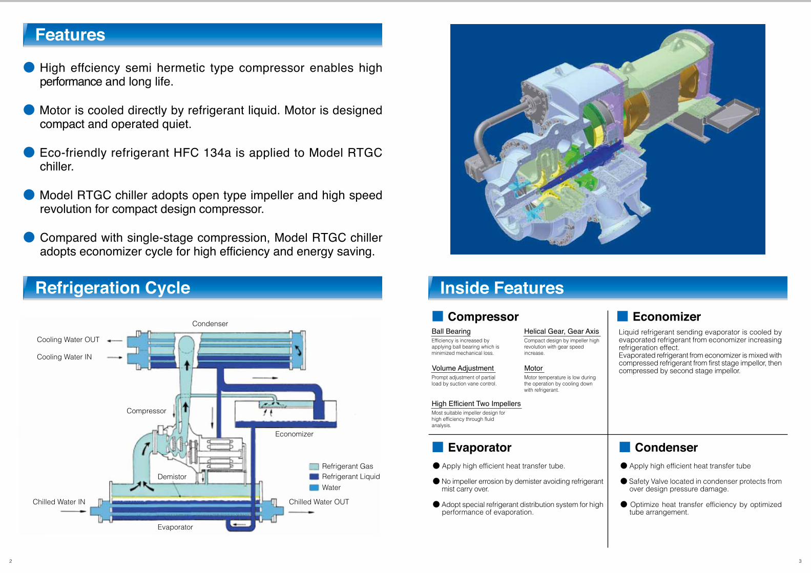
■ Compressor ■ Economizer
■ Evaporator ■ Condenser
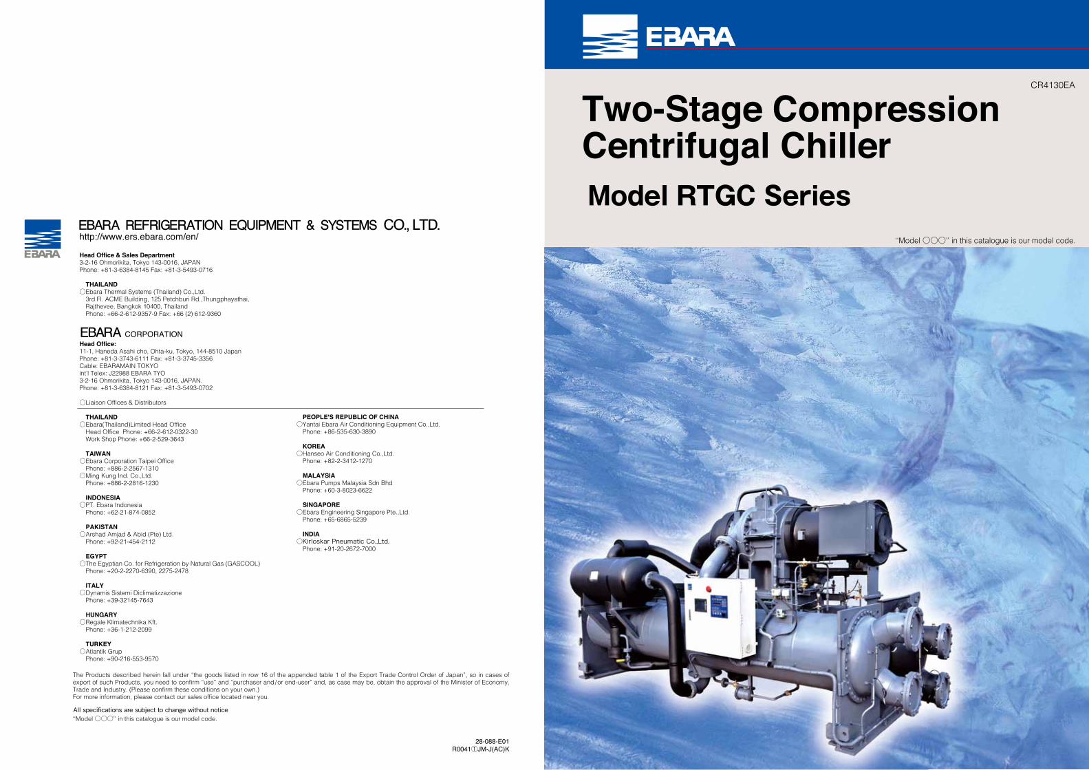
Inside FeaturesRefrigeration Cycle
Features
2 3
Cooling Water OUT
Condenser
Compressor
Demistor
Evaporator
Economizer
Refrigerant Gas
Ball Bearing Helical Gear, Gear Axis
Refrigerant Liquid
Water
Cooling Water IN
Chilled Water IN Chilled Water OUT
Efficiency is increased byapplying ball bearing which isminimized mechanical loss.
High Efficient Two ImpellersMost suitable impeller design forhigh efficiency through fluidanalysis.
Compact design by impeller highrevolution with gear speed increase.
Volume Adjustment MotorPrompt adjustment of partialload by suction vane control.
Motor temperature is low duringthe operation by cooling downwith refrigerant.
Liquid refrigerant sending evaporator is cooled by evaporated refrigerant from economizer increasing refrigeration effect.Evaporated refrigerant from economizer is mixed with compressed refrigerant from first stage impellor, then compressed by second stage impellor.
● Apply high efficient heat transfer tube.
● No impeller errosion by demister avoiding refrigerant mist carry over.
● Adopt special refrigerant distribution system for high performance of evaporation.
● Apply high efficient heat transfer tube
● Safety Valve located in condenser protects from over design pressure damage.
● Optimize heat transfer efficiency by optimized tube arrangement.

■Condition : 7 /32 ℃ Temperature Selection
Notes: 1) Chilled Water Temperature (IN / OUT) 12/7℃, Cooling Water Temperature (IN / OUT) 32/37℃2) Refrigerant R134a3) Water Box Max Working Pressure 1MPa4) Fouling Factor: Chilled Water; 0.018㎡K / kW (0.21 / 10000㎡h℃/ kcal), Cooling Water; 0.044㎡/ kW (0.51 / 10000㎡h℃/ kcal)5) Electric condition Frequency: 50, 60Hz, Voltage: 380V, 3kV, 6kV, 10kV Class
Machine Foundation Dimension
Water Box Nozzle Dimension
Model RTGC
2286
650
411
392.3
99
250
2
467.3
85
250
2
11.7 / 12.4
13.7 / 14.4
750
5075
2550
2700
4300
641
593
2110
600
379
362.1
98
250
2
431.2
84
250
2
11.6 / 12.2
13.5 / 14.1
700
5075
2550
2700
4300
611
559
1934
550
349
331.9
98
250
2
395.7
83
250
2
11.4 / 12.1
13.2 / 13.9
650
5075
2550
2700
4300
582
529
2462
700
444
422.4
100
250
2
503.4
85
250
2
11.9 / 12.5
14.0 / 14.7
775
5075
2550
2700
4300
671
625
2638
750
480
452.6
112
250
2
540.1
97
250
2
11.9 / 12.6
14.0 / 14.8
800
5075
2550
2700
4300
671
625
2814
800
506
482.8
98
300
2
575.1
83
300
2
15.0 / 15.3
17.6 / 17.9
820
5100
2900
2850
4300
839
762
3517
1000
636
603.5
100
300
2
719.4
86
300
2
15.6 / 15.9
18.5 / 18.9
950
5100
2900
2850
4300
957
893
2990
850
537
513.5
99
300
2
611.0
84
300
2
15.2 / 15.5
17.9 / 18.1
850
5100
2900
2850
4300
868
795
3869
1100
712
663.8
118
300
2
793.6
102
300
2
15.7 / 16.0
18.6 / 19.0
1000
5100
2900
2850
4300
957
893
4221
1200
757
724.2
126
350
2
862.4
101
400
2
21.4 / 21.5
25.6 / 25.7
1250
5500
3275
3285
4600
1230
1129
4572
1300
820
784.5
127
350
2
934.2
101
400
2
− / 21.7
− / 26.0
1320
5500
3275
3285
4600
1284
1194
4924
1400
884
844.9
128
350
2
1006.3
102
400
2
− / 22.0
− / 26.3
1400
5500
3275
3285
4600
1341
1259
5276
1500
954
905.2
129
350
2
1079.2
103
400
2
− / 22.1
− / 26.4
1450
5500
3275
3285
4600
1397
1324
5627
1600
1054
965.6
161
350
2
1157.6
131
400
2
− / 22.3
− / 26.7
1500
5500
3275
3285
4600
1397
1324
3341
950
602
573.3
99
300
2
683.1
85
300
2
15.5 / 15.6
18.3 / 18.4
900
5100
2900
2850
4300
928
862
3165
900
568
543.1
99
300
2
646.7
84
300
2
15.3 / 15.6
18.1 / 18.3
880
5100
2900
2850
4300
898
828
Specification
065A060A055A 070A 075A 080A 100A085A 110A 120A 130A 140A 150A 160A095A090A
ABC
Model RTGC
4805
530
2250
Model RTGC055A-075AModel RTGC080A-110AModel RTGC120A-160A
Nozzle Dimensions2040
2290
2600
1020
1145
1300
277
365
495
548
660
830
505
605
735
579
700
720
4805
530
2250
4805
530
2250
4805
530
2250
4805
530
2250
4805
530
2500
4805
530
2500
4805
530
2500
4805
530
2500
4805
530
2500
4805
530
2500
5093
530
2810
5093
530
2810
5093
530
2810
5093
530
2810
5093
530
2810
055A
A B C D E F
060A 065A 070A 075A 080A 085A 090A 095A 100A 110A 120A 130A 140A 150A 160A
Cooling Capacity
Motor Input
Approx. Dry Rigging Mass (380V/3,6,10kV)Approx. Running Mass (380V/3,6,10kV)Refrigerant Filler ContentMaximum Length Dimension (L)Maximum Width Dimension (W)Maximum Height Dimension (H)Tube Removal Space (Either End) (A)Chilled Water RetainCooling Water Retain
Flow RatePressure dropNozzle sizePass numberFlow RatePressure dropNozzle sizePass number
kWUSRT
kW㎥ /hkPa
A (mm)ー㎥ /hkPa
A (mm)ーttkg
mmmmmmmmℓℓ
4 5
Maintenance space for compressordisassembly is required 2000mmhigh above the machine includinglifting apparatus
Maintenance space for compressor disassembly is required 1250mm holizontal direction
Maintenance space
Minimum1000mm
Minimum1200mm
W
Tube removal space(either end)
H
L
A
Chi
lled
Wat
erC
oolin
g W
ater
5050
C10
0 5020-3
0
AB B 100
(REAR SIDE)
(FRONT SIDE)
DRAIN SEE THE MACHINEISOLATION DETAIL
BASE CONCRETE
MORTAR
SOLE PLATESHEARFLEX PAD
MACHINE FOOT
Evaporator
A
B
E
CD
F
Condenser
Cooling WaterLeaving Nozzle
Cooling WaterEntering Nozzle
Chilled WaterEntering Nozzle
Chilled WaterLeaving Nozzle
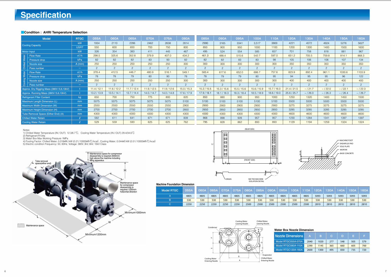
■Condition : AHRI Temperature Selection
Notes: 1) Chilled Water Temperature (IN / OUT) 12.3/6.7℃, Cooling Water Temperature (IN / OUT) 29.4/34.6℃2) Refrigerant R134a3) Water Box Max Working Pressure 1MPa4) Fouling Factor: Chilled Water; 0.018㎡K/kW (0.21 /10000㎡h℃/ kcal), Cooling Water; 0.044㎡ / kW (0.51 /10000㎡h℃/ kcal)5) Electric condition Frequency: 50, 60Hz, Voltage: 380V, 3kV, 6kV, 10kV Class
Machine Foundation Dimension
Water Box Nozzle Dimension
2286
650
383
352.8
82
250
2
446.7
79
250
2
11.7 / 12.4
13.7 / 14.4
750
5075
2550
2700
4300
641
593
2110
600
354
325.6
82
250
2
412.5
78
250
2
11.6 / 12.2
13.5 / 14.1
700
5075
2550
2700
4300
611
559
1934
550
326
298.5
82
250
2
378.4
78
250
2
11.4 / 12.1
13.2 / 13.9
650
5075
2550
2700
4300
582
529
2462
700
411
379.9
83
250
2
480.9
80
250
2
11.9 / 12.5
14.0 / 14.7
775
5075
2550
2700
4300
671
625
2638
750
445
407.0
93
250
2
516.1
90
250
2
11.9 / 12.6
14.0 / 14.8
800
5075
2550
2700
4300
671
625
2814
800
467
434.2
82
300
2
549.1
78
300
2
15.0 / 15.3
17.6 / 17.9
820
5100
2900
2850
4300
839
762
3,517
1000
585
542.7
83
300
2
686.7
80
300
2
15.6 / 15.9
18.5 / 18.9
950
5100
2900
2850
4300
957
893
2990
850
495
461.3
82
300
2
583.4
78
300
2
15.2 / 15.5
17.9 / 18.1
850
5100
2900
2850
4300
868
795
3869
1100
657
597.0
98
300
2
757.6
95
300
2
15.7 / 16.0
18.6 / 19.0
1000
5100
2900
2850
4300
957
893
4221
1200
701
651.2
105
350
2
823.9
94
400
2
21.4 / 21.5
25.6 / 25.7
1250
5500
3275
3285
4600
1230
1129
4572
1300
758
705.5
106
350
2
892.4
95
400
2
− / 21.7
− / 26.0
1320
5500
3275
3285
4600
1284
1194
4924
1400
818
759.8
106
350
2
961.1
95
400
2
− / 22.0
− / 26.3
1400
5500
3275
3285
4600
1341
1259
5276
1500
881
814.1
107
350
2
1030.6
96
400
2
− / 22.1
− / 26.4
1450
5500
3275
3285
4600
1397
1324
5627
1600
967
868.3
134
350
2
1103.9
122
400
2
− / 22.3
− / 26.7
1500
5500
3275
3285
4600
1397
1324
3341
950
554
515.6
83
300
2
652.0
79
300
2
15.5 / 15.6
18.3 / 18.4
900
5100
2900
2850
4300
928
862
3165
900
524
488.4
82
300
2
617.6
79
300
2
15.3 / 15.6
18.1 / 18.3
880
5100
2900
2850
4300
898
828
Specification
065A060A055A 070A 075A 080A 100A085A 110A 120A 130A 140A 150A 160A095A090AModel RTGCkW
USRTkW㎥ /hkPa
A (mm)ー㎥ /hkPa
A (mm)ーttkg
mmmmmmmmℓℓ
Cooling Capacity
Motor Input
Approx. Dry Rigging Mass (380V/3,6,10kV)Approx. Running Mass (380V/3,6,10kV)Refrigerant Filler ContentMaximum Length Dimension (L)Maximum Width Dimension (W)Maximum Height Dimension (H)Tube Removal Space (Either End) (A)Chilled Water RetainCooling Water Retain
Flow RatePressure dropNozzle sizePass numberFlow RatePressure dropNozzle sizePass number
ABC
Model RTGC
4805
530
2250
Model RTGC055A-075AModel RTGC080A-110AModel RTGC120A-160A
Nozzle Dimensions2040
2290
2600
1020
1145
1300
277
365
495
548
660
830
505
605
735
579
700
720
4805
530
2250
4805
530
2250
4805
530
2250
4805
530
2250
4805
530
2500
4805
530
2500
4805
530
2500
4805
530
2500
4805
530
2500
4805
530
2500
5093
530
2810
5093
530
2810
5093
530
2810
5093
530
2810
5093
530
2810
055A
A B C D E F
060A 065A 070A 075A 080A 085A 090A 095A 100A 110A 120A 130A 140A 150A 160A
6 7
Maintenance space for compressordisassembly is required 2000mmhigh above the machine includinglifting apparatus
Maintenance space for compressor disassembly is required 1250mm holizontal direction
Maintenance space
Minimum1000mm
Minimum1200mm
W
Tube removal space(either end)
H
L
A
Chi
lled
Wat
erC
oolin
g W
ater
5050
C10
0 5020-3
0
AB B 100
(REAR SIDE)
(FRONT SIDE)
DRAIN SEE THE MACHINEISOLATION DETAIL
BASE CONCRETE
MORTAR
SOLE PLATESHEARFLEX PAD
MACHINE FOOT
Evaporator
A
B
E
CD
F
Condenser
Cooling WaterLeaving Nozzle
Cooling WaterEntering Nozzle
Chilled WaterEntering Nozzle
Chilled WaterLeaving Nozzle
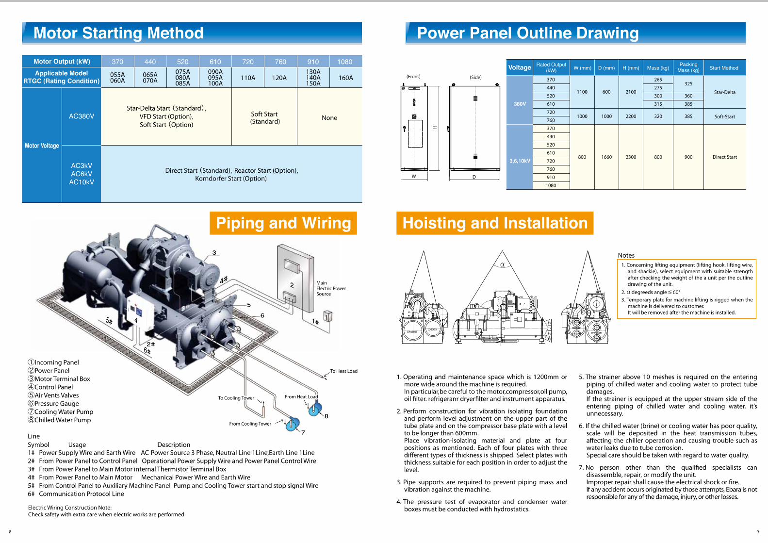
①Incoming Panel②Power Panel③Motor Terminal Box④Control Panel⑤Air Vents Valves⑥Pressure Gauge⑦Cooling Water Pump⑧Chilled Water Pump
LineSymbol Usage Description1# Power Supply Wire and Earth Wire AC Power Source 3 Phase, Neutral Line 1Line,Earth Line 1Line2# From Power Panel to Control Panel Operational Power Supply Wire and Power Panel Control Wire3# From Power Panel to Main Motor internal Thermistor Terminal Box4# From Power Panel to Main Motor Mechanical Power Wire and Earth Wire5# From Control Panel to Auxiliary Machine Panel Pump and Cooling Tower start and stop signal Wire6# Communication Protocol Line
Motor Starting Method Power Panel Outline Drawing
D
H
W
(Front) (Side)
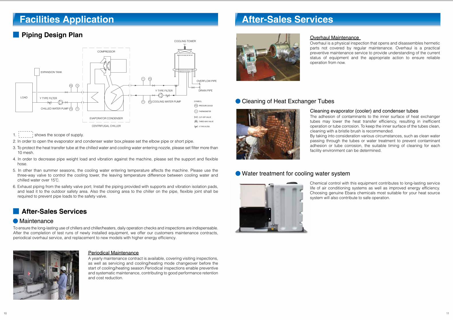
1. Concerning lifting equipment (lifting hook, lifting wire, and shackle), select equipment with suitable strength after checking the weight of the a unit per the outline drawing of the unit.
2.α degreeds angle ≦ 60°3. Temporary plate for machine lifting is rigged when the
machine is delivered to customer.It will be removed after the machine is installed.
Notesα
2#
45#
6#
3
5
6
8
7
1#
4#
98
Motor Output (kW) 370
055A060A
065A070A
075A080A085A
090A095A100A
130A140A150A
110A 120A 160A
440 520 610 720 760 910 1080
Motor Voltage
Applicable ModelRTGC (Rating Condition)
AC380V
AC3kVAC6kVAC10kV
Piping and Wiring
Star-Delta Start (Standard),VFD Start (Option),Soft Start (Option)
Soft Start (Standard)
Direct Start (Standard), Reactor Start (Option),Korndorfer Start (Option)
None
MainElectric PowerSource
From Heat LoadFrom Heat Load
To Heat LoadTo Heat Load
From Cooling Tower
To Cooling TowerTo Cooling Tower
Hoisting and Installation
1. Operating and maintenance space which is 1200mm or more wide around the machine is required.In particular,be careful to the motor,compressor,oil pump, oil �lter. refrigeranr dryer�lter and instrument apparatus.
2. Perform construction for vibration isolating foundation and perform level adjustment on the upper part of the tube plate and on the compressor base plate with a level to be longer than 600mm.Place vibration-isolating material and plate at four positions as mentioned. Each of four plates with three di�erent types of thickness is shipped. Select plates with thickness suitable for each position in order to adjust the level.
3. Pipe supports are required to prevent piping mass and vibration against the machine.
4. The pressure test of evaporator and condenser water boxes must be conducted with hydrostatics.
5. The strainer above 10 meshes is required on the entering piping of chilled water and cooling water to protect tube damages. If the strainer is equipped at the upper stream side of the entering piping of chilled water and cooling water, it’s unnecessary.
6. If the chilled water (brine) or cooling water has poor quality, scale will be deposited in the heat transmission tubes, a�ecting the chiller operation and causing trouble such as water leaks due to tube corrosion. Special care should be taken with regard to water quality.
7. No person other than the quali�ed specialists can disassemble, repair, or modify the unit. Improper repair shall cause the electrical shock or �re. If any accident occurs originated by those attempts, Ebara is not responsible for any of the damage, injury, or other losses.
D (mm)
380V
3,6,10kV
Voltage H (mm) Mass (kg)
265
275
300
315
PackingMass (kg)
325
360
385
Start Method
Star-Delta
Soft-Start
Direct Start
W (mm)
1100
1000
800
600
1000
1660
2100
2200
2300
320
800
385
900
Rated Output(kW)
370
440
520
610
720
760
370
440
520
610
720
760
910
1080
Electric Wiring Construction Note:Check safety with extra care when electric works are performed
■ After-Sales Services
■ Piping Design Plan
Facilities Application After-Sales Services
● Maintenance
● Cleaning of Heat Exchanger Tubes
● Water treatment for cooling water system
10 11
1. shows the scope of supply.
2. In order to open the evaporator and condenser water box,please set the elbow pipe or short pipe.
3. To protect the heat transfer tube at the chilled water and cooling water entering nozzle, please set filter more than 10 mesh.
4. In order to decrease pipe weight load and vibration against the machine, please set the support and flexible hose.
5. In other than summer seasons, the cooling water entering temperature affects the machine. Please use the three-way valve to control the cooling tower, the leaving temperature difference between cooling water and chilled water over 15℃.
6. Exhaust piping from the safety valve port; Install the piping provided with supports and vibration isolation pads, and lead it to the outdoor safety area. Also the closing area to the chiller on the pipe, flexible joint shall be required to prevent pipe loads to the safety valve.
To ensure the long-lasting use of chillers and chiller/heaters, daily operation checks and inspections are indispensable. After the completion of test runs of newly installed equipment, we offer our customers maintenance contracts, periodical overhaul service, and replacement to new models with higher energy efficiency.
A yearly maintenance contract is available, covering visiting inspections, as well as servicing and cooling/heating mode changeover before the start of cooling/heating season.Periodical inspections enable preventive and systematic maintenance, contributing to good performance retention and cost reduction.
Periodical Maintenance
EXPANSION TANK
Y TYPE FILTER
PG T1
PGT1
PG
PG
T1
T1 :THERMOMETER
:CUT-OFF VALVE
:Y TYPE FILTER
:THREE-WAY VALVE
:PRESSURE GAUGE
PG T1
LOAD
CHILLED WATER PUMP
EVAPORATOR CONDENSER
COMPRESSOR
COOLING WATER PUMP
Y TYPE FILTER
OVERFLOW PIPE
COOLING TOWER
SYMBOL
DRAIN PIPE
CENTRIFUGAL CHILLER
Overhaul is a physical inspection that opens and disassembles hermetic parts not covered by regular maintenance. Overhaul is a practical preventive maintenance service to provide understanding of the current status of equipment and the appropriate action to ensure reliable operation from now.
Overhaul Maintenance
The adhesion of contaminants to the inner surface of heat exchanger tubes may lower the heat transfer efficiency, resulting in inefficient operation or tube corrosion. To keep the inner surface of the tubes clean, cleaning with a bristle brush is recommended.By taking into consideration various circumstances, such as clean water passing through the tubes or water treatment to prevent contaminant adhesion or tube corrosion, the suitable timing of cleaning for each facility environment can be determined.
Cleaning evaporator (cooler) and condenser tubes
Chemical control with this equipment contributes to long-lasting service life of air conditioning systems as well as improved energy efficiency. Choosing genuine Ebara chemicals most suitable for your heat source system will also contribute to safe operation.