Embed Size (px)
Citation preview
®Mohawk InnovativeTechnology, Inc.
Oil-Free Centrifugal
Hydrogen Compression Technology Demonstration
PI: Hooshang Heshmat, PhD
Mohawk Innovative Technology, Inc. Albany, NY
Hydrogen and Fuel Cells Program Annual Merit Review and Peer Evaluation Meeting Arlington VA
Project ID # PD016
May 15, 2013
Fuel Cell Technologies Program
This presentation does not contain any proprietary, confidential, or otherwise restricted information
®Mohawk InnovativeTechnology, Inc.
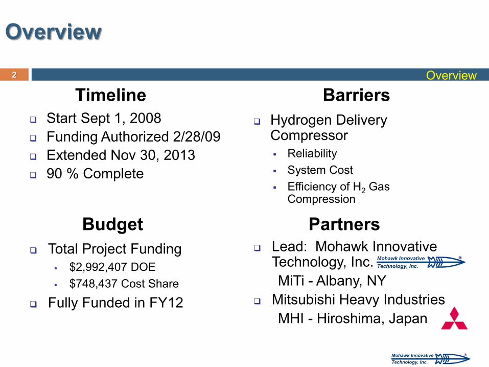
Start Sept 1, 2008 Funding Authorized 2/28/09 Extended Nov 30, 2013 90 % Complete
Hydrogen Delivery Compressor Reliability System Cost Efficiency of H2 Gas
Compression
Total Project Funding $2,992,407 DOE $748,437 Cost Share
Fully Funded in FY12
Timeline
Budget
Barriers
Lead: Mohawk Innovative Technology, Inc. MiTi - Albany, NY
Mitsubishi Heavy Industries MHI - Hiroshima, Japan
Partners
Overview
2
®Mohawk InnovativeTechnology, Inc.
Overview
®Mohawk InnovativeTechnology, Inc.
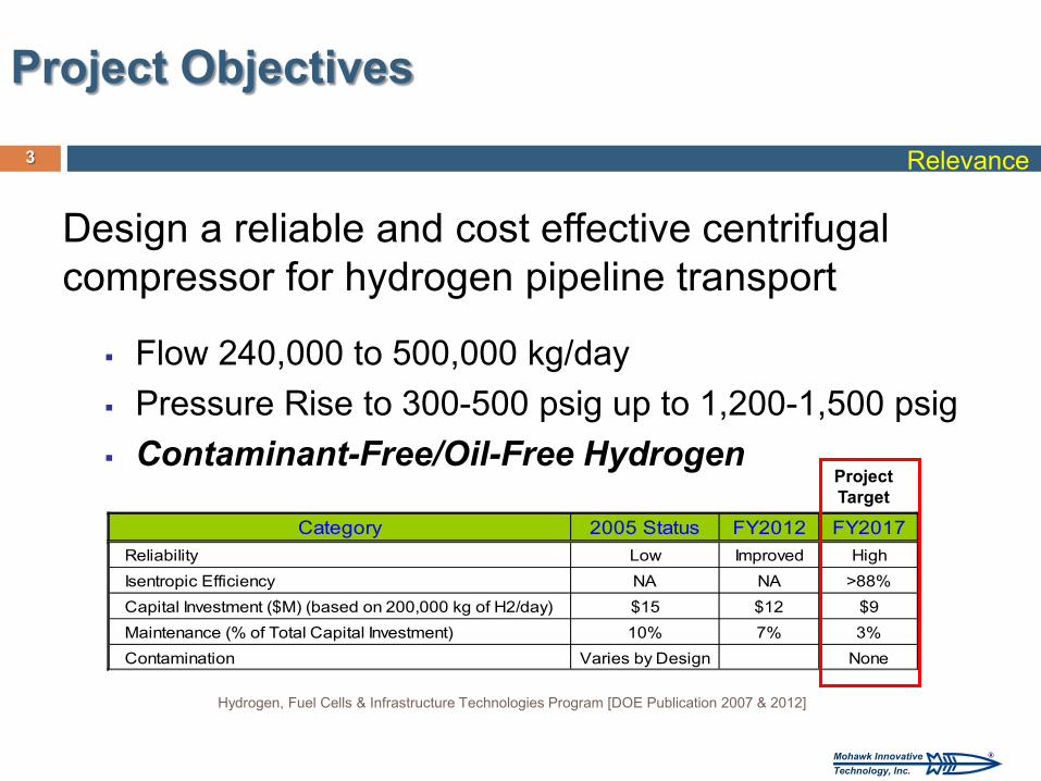
Design a reliable and cost effective centrifugal compressor for hydrogen pipeline transport
Flow 240,000 to 500,000 kg/day Pressure Rise to 300-500 psig up to 1,200-1,500 psig Contaminant-Free/Oil-Free Hydrogen
Category 2005 Status FY2012 FY2017Reliability Low Improved HighIsentropic Efficiency NA NA >88%Capital Investment ($M) (based on 200,000 kg of H2/day) $15 $12 $9Maintenance (% of Total Capital Investment) 10% 7% 3%Contamination Varies by Design None
Hydrogen, Fuel Cells & Infrastructure Technologies Program [DOE Publication 2007 & 2012]
Project Target
3
Project Objectives
Relevance
®Mohawk InnovativeTechnology, Inc.
4
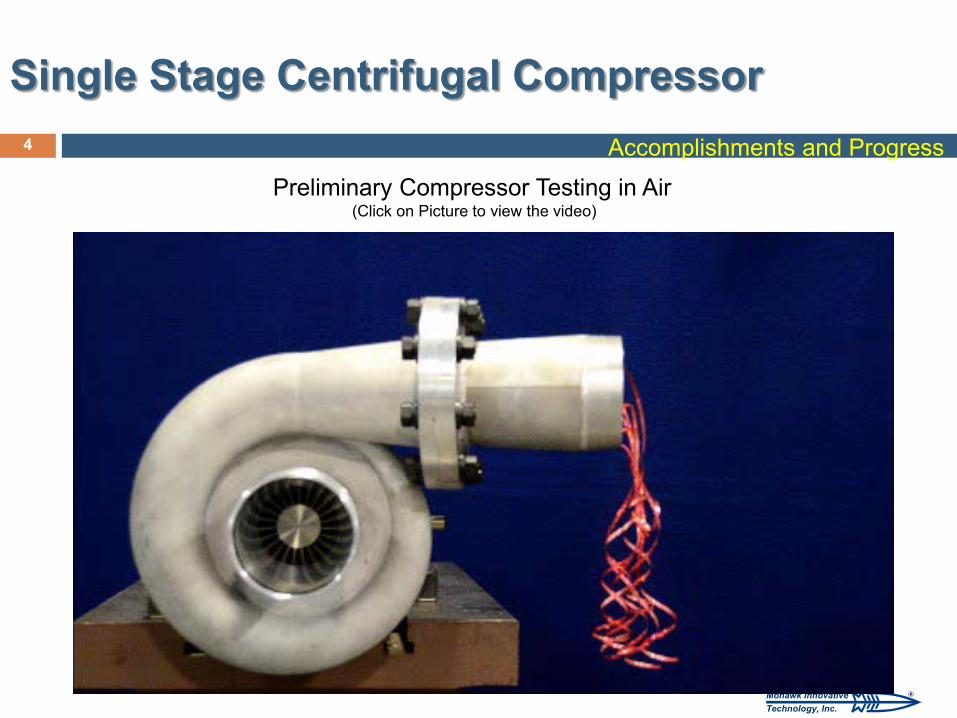
Single Stage Centrifugal Compressor Accomplishments and Progress
Preliminary Compressor Testing in Air (Click on Picture to view the video)
®Mohawk InnovativeTechnology, Inc.
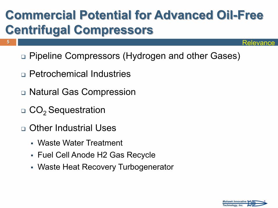
Commercial Potential for Advanced Oil-Free Centrifugal Compressors
Pipeline Compressors (Hydrogen and other Gases)
Petrochemical Industries
Natural Gas Compression
CO2 Sequestration
Other Industrial Uses Waste Water Treatment Fuel Cell Anode H2 Gas Recycle Waste Heat Recovery Turbogenerator
5 Relevance
®Mohawk InnovativeTechnology, Inc.
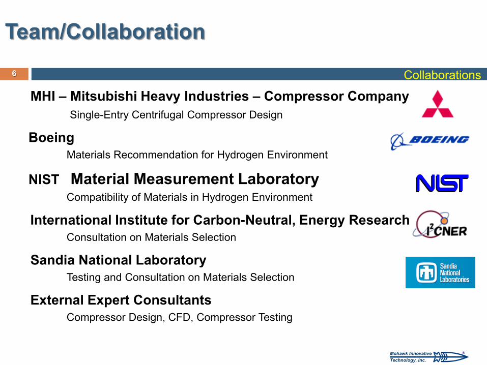
MHI – Mitsubishi Heavy Industries – Compressor Company Single-Entry Centrifugal Compressor Design
Boeing Materials Recommendation for Hydrogen Environment
NIST Material Measurement Laboratory Compatibility of Materials in Hydrogen Environment
International Institute for Carbon-Neutral, Energy Research Consultation on Materials Selection
Sandia National Laboratory Testing and Consultation on Materials Selection
External Expert Consultants Compressor Design, CFD, Compressor Testing
Team/Collaboration 6 Collaborations
®Mohawk InnovativeTechnology, Inc.
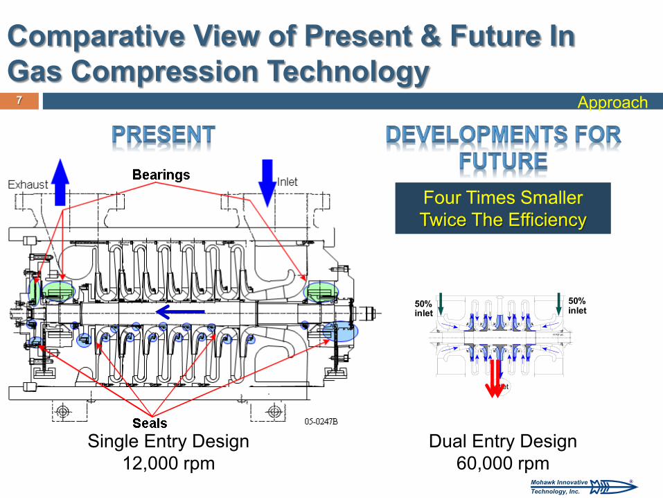
Comparative View of Present & Future In Gas Compression Technology
7
50%inlet
50%inlet
outlet
Single Entry Design 12,000 rpm
Dual Entry Design 60,000 rpm
Four Times Smaller Twice The Efficiency
Approach
®Mohawk InnovativeTechnology, Inc.
8
Copyright © 2009 MiTi®
8
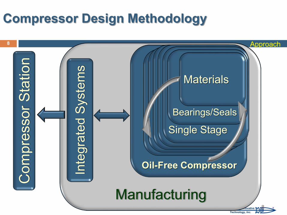
Inte
grat
ed S
yste
ms
Com
pres
sor S
tatio
n
Single Stage
Bearings/Seals
Materials
Oil-Free Compressor
Manufacturing
Compressor Design Methodology
Approach
®Mohawk InnovativeTechnology, Inc.
Demonstrate Feasibility of Very High Speed Hydrogen Centrifugal Compressor
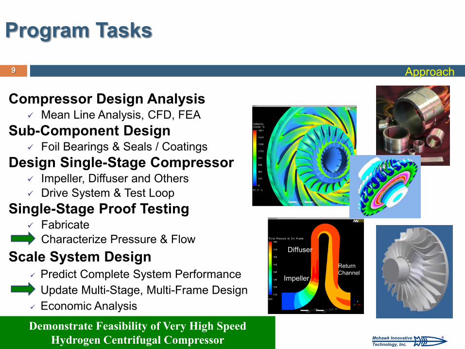
Program Tasks
Compressor Design Analysis Mean Line Analysis, CFD, FEA
Sub-Component Design Foil Bearings & Seals / Coatings
Design Single-Stage Compressor Impeller, Diffuser and Others Drive System & Test Loop
Single-Stage Proof Testing Fabricate Characterize Pressure & Flow
Scale System Design Predict Complete System Performance Update Multi-Stage, Multi-Frame Design Economic Analysis
9
Impeller
Diffuser
Return Channel
Approach
®Mohawk InnovativeTechnology, Inc.
10
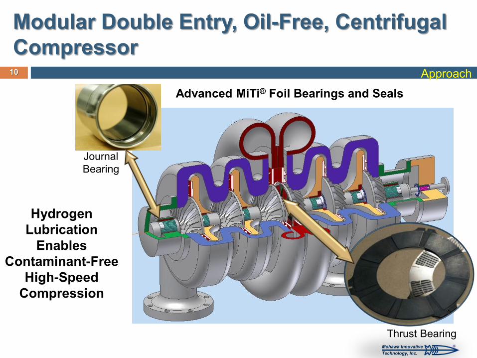
Journal Bearing
Thrust Bearing
Modular Double Entry, Oil-Free, Centrifugal Compressor
Approach
Hydrogen Lubrication
Enables Contaminant-Free
High-Speed Compression
Advanced MiTi® Foil Bearings and Seals
®Mohawk InnovativeTechnology, Inc.
0.0
0.1
0.2
0.3
0.4
0.5
0 15,000 30,000 45,000 60,000 75,000
Disp
lace
men
t (in
x10-3
)
Speed (rpm)
Rotor Motion Equivalent to Mechanical Runout at
60,000 rpm
Accomplishments and Progress
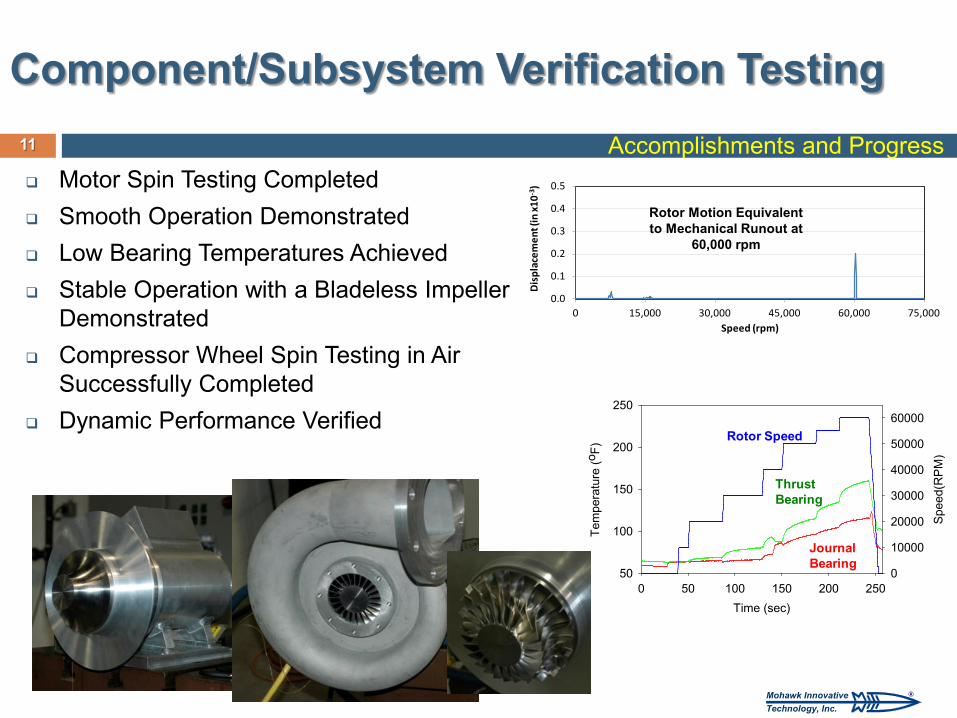
Component/Subsystem Verification Testing
Motor Spin Testing Completed Smooth Operation Demonstrated Low Bearing Temperatures Achieved Stable Operation with a Bladeless Impeller
Demonstrated Compressor Wheel Spin Testing in Air
Successfully Completed Dynamic Performance Verified
11
Time (sec)0 50 100 150 200 250
Tem
pera
ture
(oF)
50
100
150
200
250
Spe
ed(R
PM
)
0
10000
20000
30000
40000
50000
60000
Thrust Bearing
Journal Bearing
Rotor Speed
®Mohawk InnovativeTechnology, Inc.
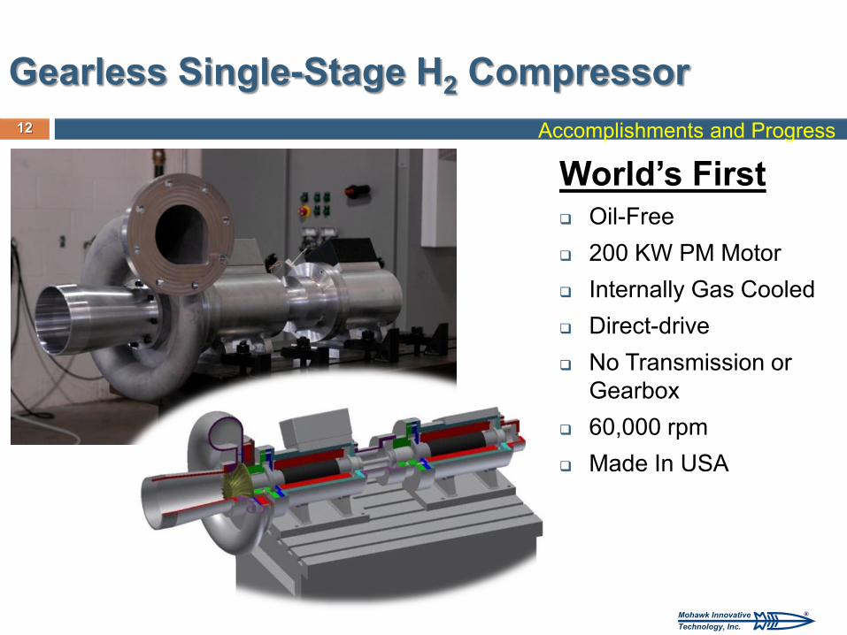
World’s First Oil-Free 200 KW PM Motor Internally Gas Cooled Direct-drive No Transmission or
Gearbox 60,000 rpm Made In USA
Accomplishments and Progress
Gearless Single-Stage H2 Compressor 12
®Mohawk InnovativeTechnology, Inc.
13
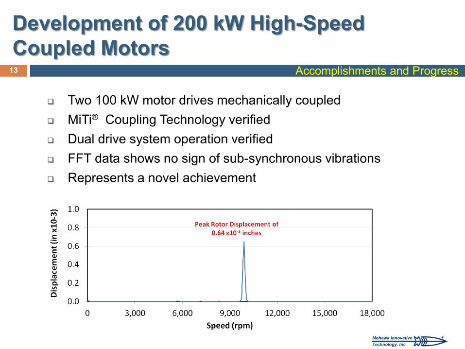
Development of 200 kW High-Speed Coupled Motors
Two 100 kW motor drives mechanically coupled MiTi® Coupling Technology verified Dual drive system operation verified FFT data shows no sign of sub-synchronous vibrations Represents a novel achievement
Accomplishments and Progress
®Mohawk InnovativeTechnology, Inc.
14
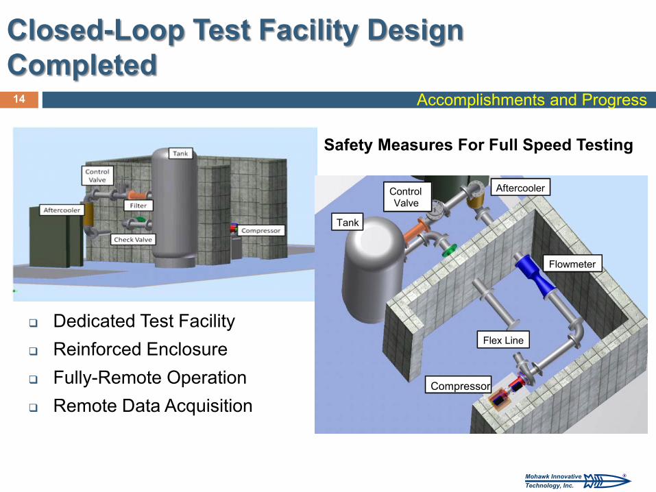
Closed-Loop Test Facility Design Completed
Dedicated Test Facility Reinforced Enclosure Fully-Remote Operation Remote Data Acquisition
Accomplishments and Progress
Safety Measures For Full Speed Testing
Compressor
Flex Line
Flowmeter
Tank
Control Valve
Aftercooler
®Mohawk InnovativeTechnology, Inc.
15
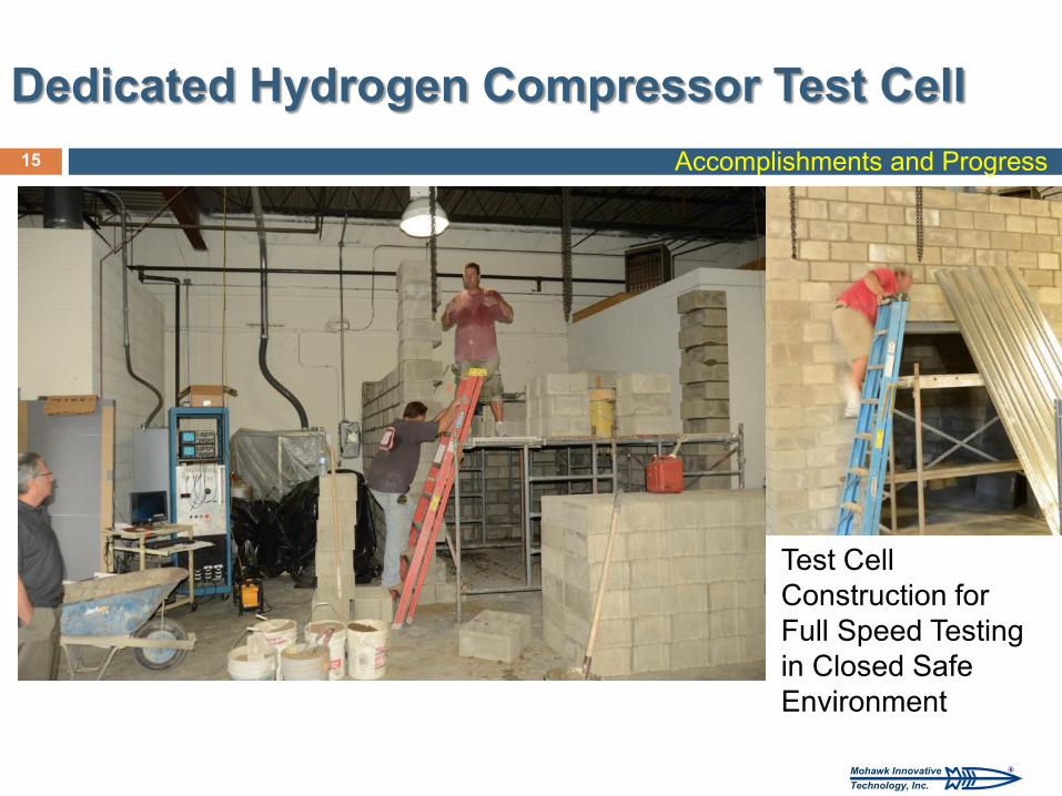
Dedicated Hydrogen Compressor Test Cell Accomplishments and Progress
Test Cell Construction for Full Speed Testing in Closed Safe Environment
®Mohawk InnovativeTechnology, Inc.
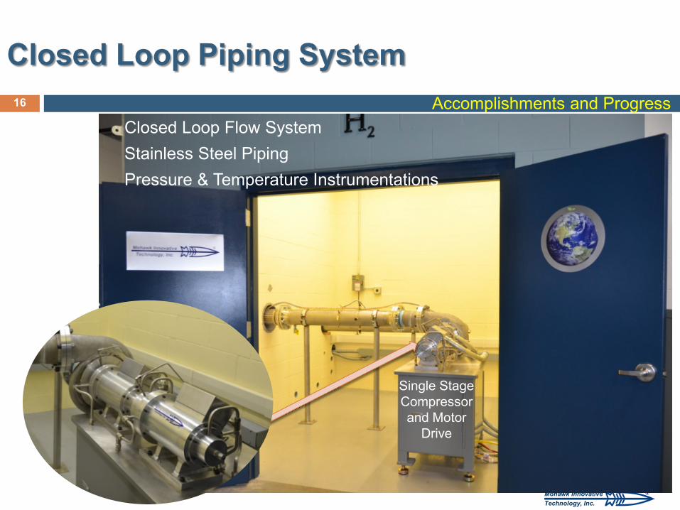
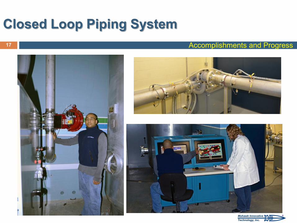
Closed Loop Piping System 16
Closed Loop Flow System Stainless Steel Piping Pressure & Temperature Instrumentations
Single Stage Compressor and Motor
Drive
Accomplishments and Progress
®Mohawk InnovativeTechnology, Inc.
17
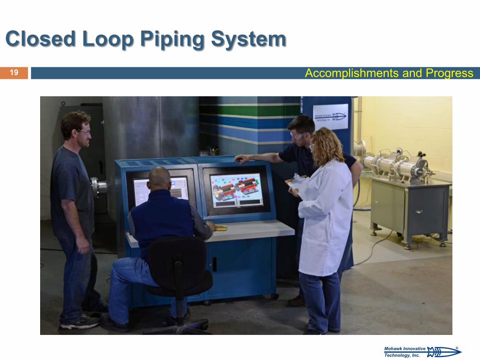
Closed Loop Piping System Accomplishments and Progress
®Mohawk InnovativeTechnology, Inc.
18
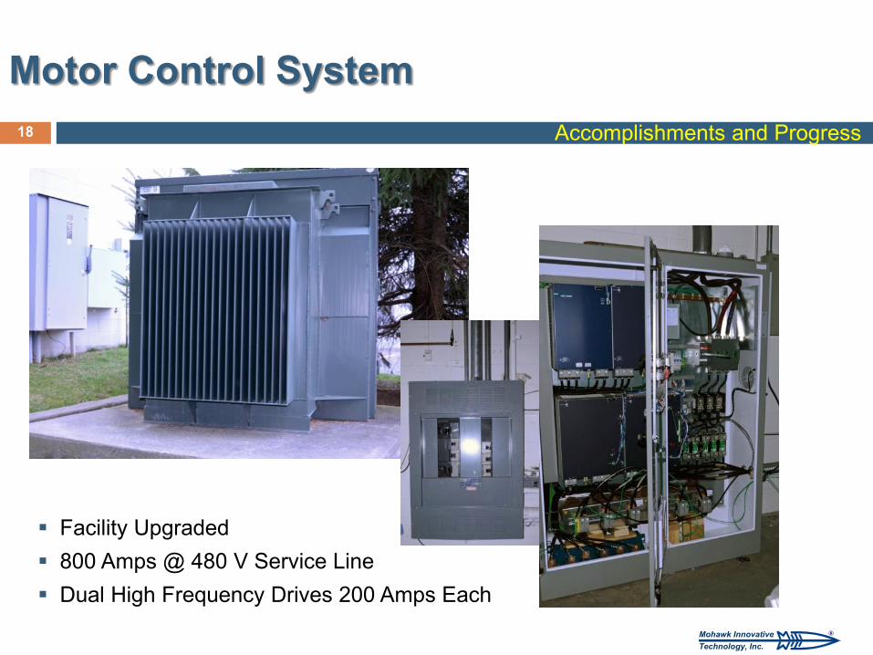
Motor Control System Accomplishments and Progress
Facility Upgraded 800 Amps @ 480 V Service Line Dual High Frequency Drives 200 Amps Each
®Mohawk InnovativeTechnology, Inc.
19
Closed Loop Piping System Accomplishments and Progress
®Mohawk InnovativeTechnology, Inc.
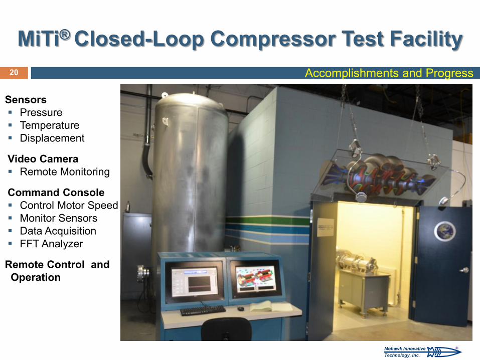
MiTi® Closed-Loop Compressor Test Facility
20 Accomplishments and Progress
Sensors Pressure Temperature Displacement
Video Camera Remote Monitoring
Command Console Control Motor Speed Monitor Sensors Data Acquisition FFT Analyzer
Remote Control and Operation
®Mohawk InnovativeTechnology, Inc.
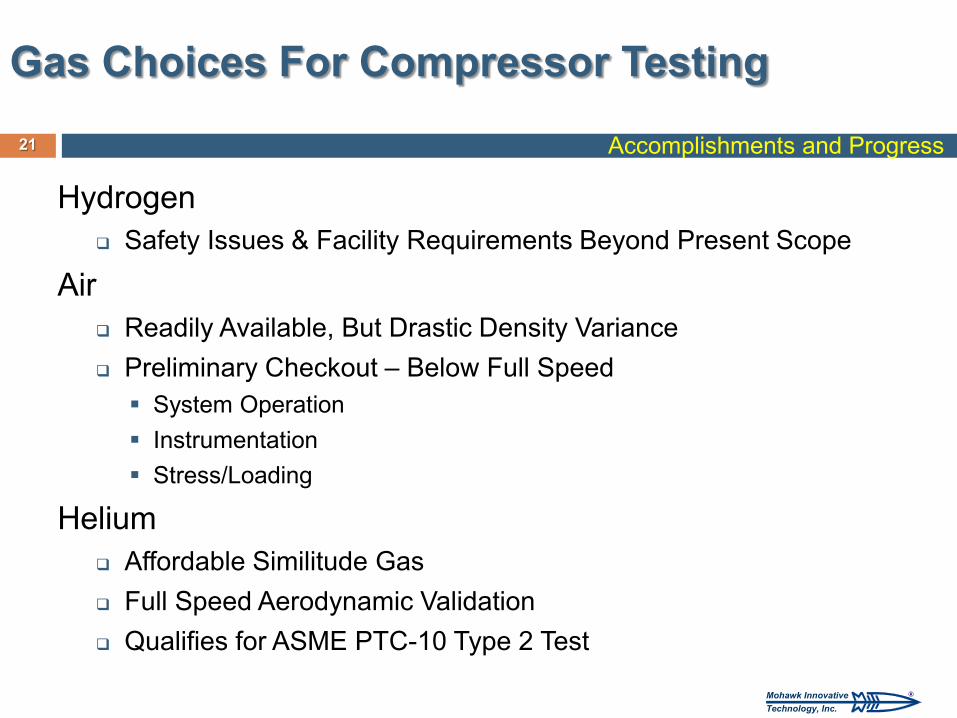
Hydrogen Safety Issues & Facility Requirements Beyond Present Scope
Air Readily Available, But Drastic Density Variance Preliminary Checkout – Below Full Speed System Operation Instrumentation Stress/Loading
Helium Affordable Similitude Gas Full Speed Aerodynamic Validation Qualifies for ASME PTC-10 Type 2 Test
21
Gas Choices For Compressor Testing
Accomplishments and Progress
®Mohawk InnovativeTechnology, Inc.
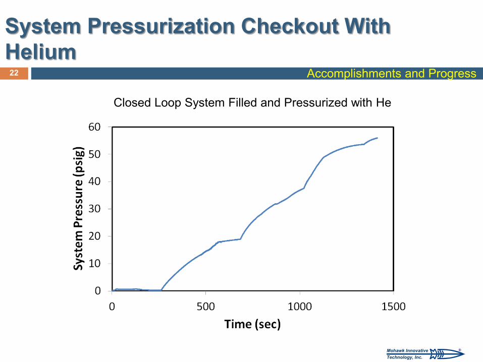
System Pressurization Checkout With Helium
22 Accomplishments and Progress
Closed Loop System Filled and Pressurized with He
®Mohawk InnovativeTechnology, Inc.
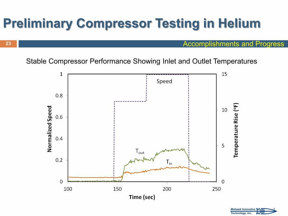
Preliminary Compressor Testing in Helium 23 Accomplishments and Progress
Stable Compressor Performance Showing Inlet and Outlet Temperatures
®Mohawk InnovativeTechnology, Inc.
Simulated Hydrogen Compressor Testing Complete Testing in Accordance with Industry Standard ASME PTC-
10 with He Validate Oil-Free Compressor with Foil Bearings and Seals
Hydrogen Compatibility Evaluation Evaluate H2 compatibility of Ti Alloy and Foil Bearing/Seal Materials
Design Refinement Estimate Multi-Frame Compressor System Performance, Total
Intercooler Heat Load and Total Driving Power Required per Frame, Based on Single Stage Test Data
Refine Estimates of Capital Costs and Compare to DOE Targets
24
Future Work (FY 13)
Planned Future Work
®Mohawk InnovativeTechnology, Inc.
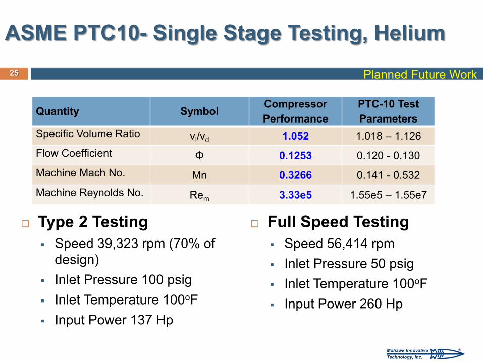
Type 2 Testing Speed 39,323 rpm (70% of
design) Inlet Pressure 100 psig Inlet Temperature 100oF Input Power 137 Hp
Quantity Symbol Compressor Performance
PTC-10 Test Parameters
Specific Volume Ratio vi/vd 1.052 1.018 – 1.126 Flow Coefficient Φ 0.1253 0.120 - 0.130 Machine Mach No. Mn 0.3266 0.141 - 0.532 Machine Reynolds No. Rem 3.33e5 1.55e5 – 1.55e7
25
ASME PTC10- Single Stage Testing, Helium
Full Speed Testing Speed 56,414 rpm Inlet Pressure 50 psig Inlet Temperature 100oF Input Power 260 Hp
Planned Future Work
®Mohawk InnovativeTechnology, Inc.
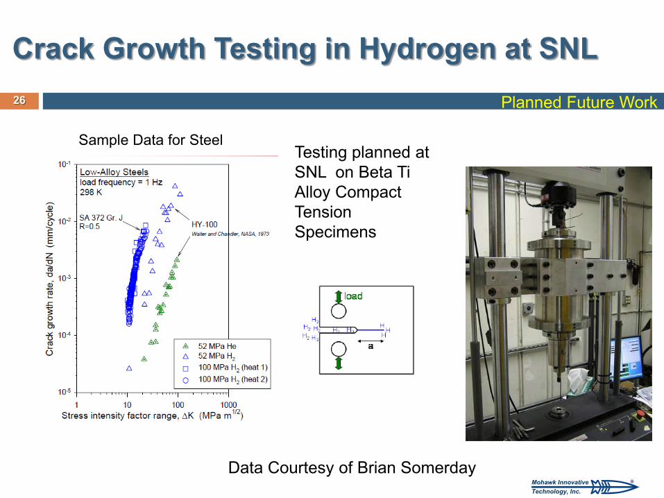
Crack Growth Testing in Hydrogen at SNL Planned Future Work 26
Testing planned at SNL on Beta Ti Alloy Compact Tension Specimens
Sample Data for Steel
Data Courtesy of Brian Somerday
®Mohawk InnovativeTechnology, Inc.
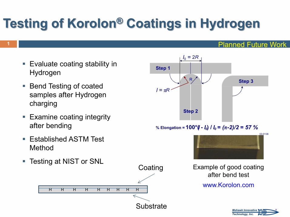
Testing of Korolon® Coatings in Hydrogen 1
Evaluate coating stability in Hydrogen
Bend Testing of coated samples after Hydrogen charging
Examine coating integrity after bending
Established ASTM Test Method
Testing at NIST or SNL
Substrate
Coating
H H H H H H H H H
Planned Future Work
Example of good coating after bend test
www.Korolon.com
Step 2
R Step 3
Step 1
l 0 = 2 R
l = π R
% Elongation = 100*( l - l 0 ) / l 0 = (π-2)/2 = 57 % 03-0138
®Mohawk InnovativeTechnology, Inc.
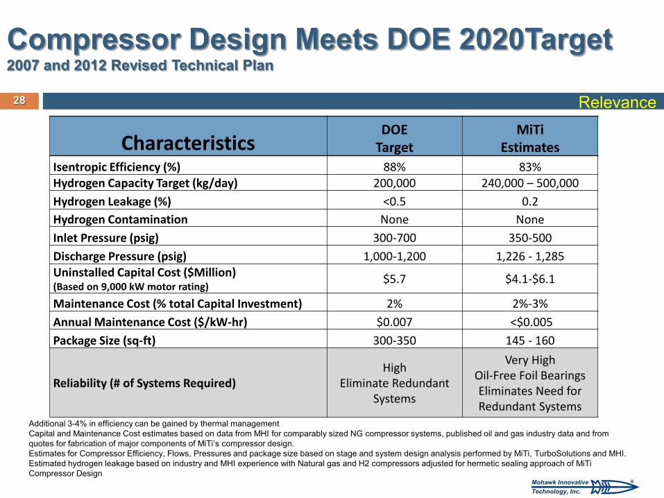
Characteristics DOE
Target MiTi
Estimates Isentropic Efficiency (%) 88% 83% Hydrogen Capacity Target (kg/day) 200,000 240,000 – 500,000 Hydrogen Leakage (%) <0.5 0.2 Hydrogen Contamination None None Inlet Pressure (psig) 300-700 350-500 Discharge Pressure (psig) 1,000-1,200 1,226 - 1,285 Uninstalled Capital Cost ($Million) (Based on 9,000 kW motor rating)
$5.7 $4.1-$6.1
Maintenance Cost (% total Capital Investment) 2% 2%-3% Annual Maintenance Cost ($/kW-hr) $0.007 <$0.005 Package Size (sq-ft) 300-350 145 - 160
Reliability (# of Systems Required) High
Eliminate Redundant Systems
Very High Oil-Free Foil Bearings Eliminates Need for Redundant Systems
28
Compressor Design Meets DOE 2020Target 2007 and 2012 Revised Technical Plan
Additional 3-4% in efficiency can be gained by thermal management Capital and Maintenance Cost estimates based on data from MHI for comparably sized NG compressor systems, published oil and gas industry data and from quotes for fabrication of major components of MiTi’s compressor design. Estimates for Compressor Efficiency, Flows, Pressures and package size based on stage and system design analysis performed by MiTi, TurboSolutions and MHI. Estimated hydrogen leakage based on industry and MHI experience with Natural gas and H2 compressors adjusted for hermetic sealing approach of MiTi Compressor Design
Relevance
®Mohawk InnovativeTechnology, Inc.
Summary
Refined Multi-Stage/Multi-Frame Compressor Concept (FY09) Established Stage Pressure Ratios and Flows Defined and Selected Optimum Operating Speeds Selected One Stage for Detailed Design and Verification Test
Conducted Detailed Compressor Design (FY10-11) Established Detailed Flow Paths Including Inlet, Impeller, Diffuser and Return Channel
Using Computational Fluid Dynamics at Several Operating Points Designed Foil Bearings and Seals Using Coupled Elasto-Hydrodynamic Analysis System Designed Using FEM Dynamic and Stress Analyses with Titanium Alloys
Completed Fabrication and Verification Testing of MiTi® Hydrogen Compressor Stage (FY12-13) Completed Testing in Air and Preliminary Testing in He Selected Double-Entry design over Single Entry Design
29 Summary
®Mohawk InnovativeTechnology, Inc.
Novel Technologies Developed by MiTi 30 Summary
Technologies Developed and Demonstrated Under This Program Advanced Foil Bearings and Seals 200 kW Oil-Free High-Speed Motor Motor Coupling Technology Oil-Free High-Speed Gearless Compressor Closed Loop Testing Facility
®Mohawk InnovativeTechnology, Inc.
31
1. Heshmat H., Walton JF., “Oil-Free Modular System Designs for Industrial Compressors and Renewable Energy Turbine Generator Systems,” Clean Technology Conference and Expo, June 21, 2010, Anaheim, CA
2. Heshmat H., Hunsberger AZ., Ren Z., Jahanmir S., Walton JF., “On the Design of a Multi-Megawatt Oil-Free Centrifugal Compressor for Hydrogen Gas Transportation and Delivery – Operation Beyond Supercritical Speeds”, Proceedings of the ASME International Mechanical Engineering Congress and Expo, November 12-18, 2010, Vancouver, BC, Canada.
3. Heshmat H., Invited Keynote, “Tribological Requirements of High-Speed Oil-Free Rotating Machinery for Hydrogen Applications,” 2011 Hydrogenous Tribology Symposium, February 3, 2011, Fukuoka, Japan.
4. Heshmat H., “Design of a Multi-Megawatt Oil-Free Centrifugal Compressor for Hydrogen Gas Transportation and Delivery,” Fuel Cell and Hydrogen Energy Expo, February 15, 2011, National Harbor, Md.
5. Heshmat, H., Hunsberger, A., Ren, Z., Jahanmir, S., and Walton, J., Invited Keynote, “Oil-Free Bearings and Seals for Centrifugal Hydrogen Compressor,” International Tribology Conference, Hiroshima, Japan, December 5, 2011.
6. Walton, JF, “Design of a Multi-Megawatt Oil-Free Centrifugal Compressor for Hydrogen Gas Transportation and Delivery”, World Hydrogen Energy Conference, Toronto, Canada, June 6, 2012.
7. MiTi presents, “Operation of the single stage compressor”. Multimedia video can be viewed at the following site: (http://www.youtube.com/watch?v=dPn0uLIdtS8).
8. H. Heshmat, A. Hunsberger, Z. Ren, S. Jahanmir, and J. F. Walton, “Oil-Free Foil-Bearings for Centrifugal Hydrogen Compressor,” Tribology Online, January 2013.
Partial List – Publications and Presentations Summary
®Mohawk InnovativeTechnology, Inc.
32
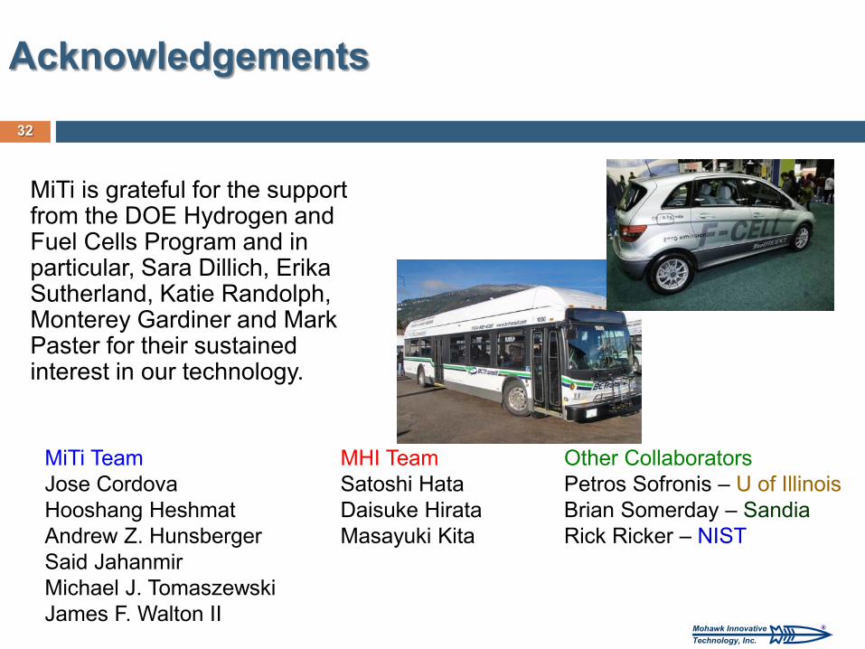
MiTi is grateful for the support from the DOE Hydrogen and Fuel Cells Program and in particular, Sara Dillich, Erika Sutherland, Katie Randolph, Monterey Gardiner and Mark Paster for their sustained interest in our technology.
Acknowledgements
MiTi Team Jose Cordova Hooshang Heshmat Andrew Z. Hunsberger Said Jahanmir Michael J. Tomaszewski James F. Walton II
MHI Team Satoshi Hata Daisuke Hirata Masayuki Kita
Other Collaborators Petros Sofronis – U of Illinois Brian Somerday – Sandia Rick Ricker – NIST

®Mohawk InnovativeTechnology, Inc.
Backup Slides 33 Backup
®Mohawk InnovativeTechnology, Inc.
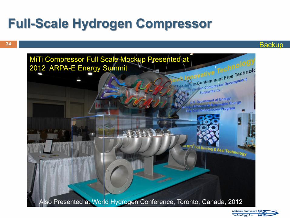
Full-Scale Hydrogen Compressor 34
MiTi Compressor Full Scale Mockup Presented at 2012 ARPA-E Energy Summit
Also Presented at World Hydrogen Conference, Toronto, Canada, 2012
Backup
®Mohawk InnovativeTechnology, Inc.
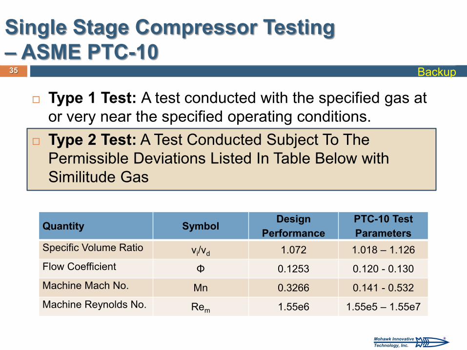
Type 1 Test: A test conducted with the specified gas at or very near the specified operating conditions.
Type 2 Test: A Test Conducted Subject To The Permissible Deviations Listed In Table Below with Similitude Gas
Quantity Symbol Design Performance
PTC-10 Test Parameters
Specific Volume Ratio vi/vd 1.072 1.018 – 1.126 Flow Coefficient Φ 0.1253 0.120 - 0.130 Machine Mach No. Mn 0.3266 0.141 - 0.532 Machine Reynolds No. Rem 1.55e6 1.55e5 – 1.55e7
35
Single Stage Compressor Testing – ASME PTC-10
Backup
®Mohawk InnovativeTechnology, Inc.
36
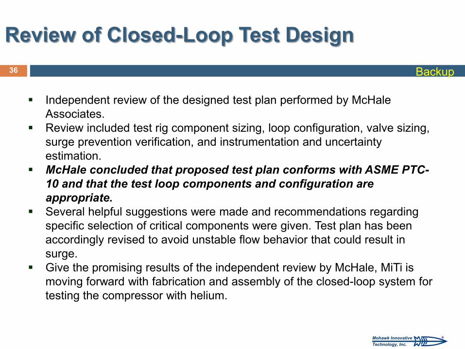
Independent review of the designed test plan performed by McHale Associates.
Review included test rig component sizing, loop configuration, valve sizing, surge prevention verification, and instrumentation and uncertainty estimation.
McHale concluded that proposed test plan conforms with ASME PTC-10 and that the test loop components and configuration are appropriate.
Several helpful suggestions were made and recommendations regarding specific selection of critical components were given. Test plan has been accordingly revised to avoid unstable flow behavior that could result in surge.
Give the promising results of the independent review by McHale, MiTi is moving forward with fabrication and assembly of the closed-loop system for testing the compressor with helium.
Review of Closed-Loop Test Design Backup
®Mohawk InnovativeTechnology, Inc.
37
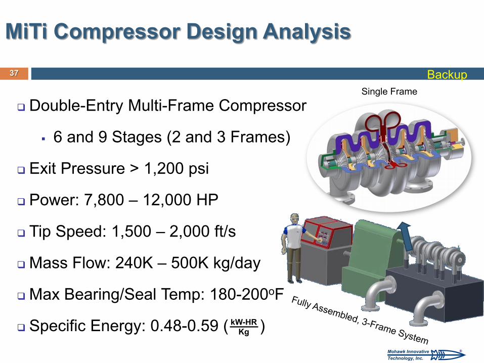
Double-Entry Multi-Frame Compressor
6 and 9 Stages (2 and 3 Frames)
Exit Pressure > 1,200 psi
Power: 7,800 – 12,000 HP
Tip Speed: 1,500 – 2,000 ft/s
Mass Flow: 240K – 500K kg/day
Max Bearing/Seal Temp: 180-200oF
Specific Energy: 0.48-0.59 ( )
MiTi Compressor Design Analysis
Single Frame
kW-HR Kg
Backup
®Mohawk InnovativeTechnology, Inc.
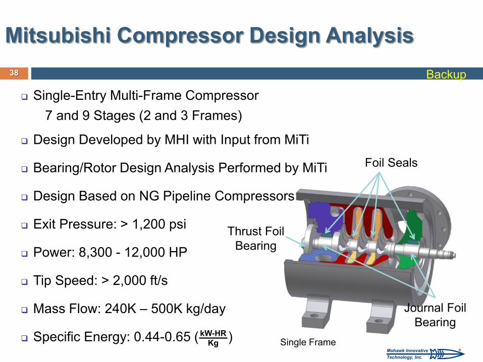
Thrust Foil Bearing
Journal Foil Bearing
Foil Seals
38
Single-Entry Multi-Frame Compressor 7 and 9 Stages (2 and 3 Frames)
Design Developed by MHI with Input from MiTi
Bearing/Rotor Design Analysis Performed by MiTi
Design Based on NG Pipeline Compressors
Exit Pressure: > 1,200 psi
Power: 8,300 - 12,000 HP
Tip Speed: > 2,000 ft/s
Mass Flow: 240K – 500K kg/day
Specific Energy: 0.44-0.65 ( )
Mitsubishi Compressor Design Analysis
kW-HR Kg Single Frame
Backup
®Mohawk InnovativeTechnology, Inc.
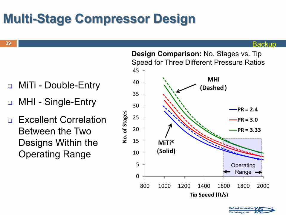
MiTi - Double-Entry
MHI - Single-Entry
Excellent Correlation Between the Two Designs Within the Operating Range
39
Design Comparison: No. Stages vs. Tip Speed for Three Different Pressure Ratios
Multi-Stage Compressor Design
0
5
10
15
20
25
30
35
40
45
800 1000 1200 1400 1600 1800 2000
No.
of S
tage
s
Tip Speed (ft/s)
PR = 2.4
PR = 3.0
PR = 3.33
MiTi®(Solid)
MHI (Dashed )
Operating Range
Backup
®Mohawk InnovativeTechnology, Inc.
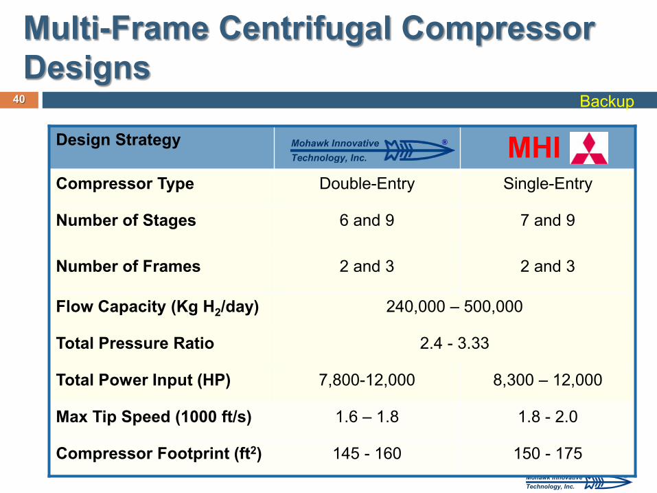
Design Strategy MHI Compressor Type Double-Entry Single-Entry
Number of Stages
6 and 9 7 and 9
Number of Frames 2 and 3 2 and 3
Flow Capacity (Kg H2/day) 240,000 – 500,000
Total Pressure Ratio 2.4 - 3.33
Total Power Input (HP) 7,800-12,000 8,300 – 12,000
Max Tip Speed (1000 ft/s) 1.6 – 1.8 1.8 - 2.0
Compressor Footprint (ft2) 145 - 160 150 - 175
40
®Mohawk InnovativeTechnology, Inc.
Multi-Frame Centrifugal Compressor Designs
Backup
®Mohawk InnovativeTechnology, Inc.
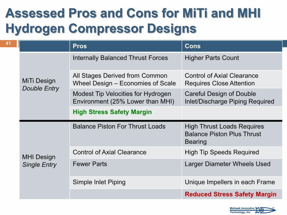
Pros Cons
MiTi Design Double Entry
Internally Balanced Thrust Forces Higher Parts Count
All Stages Derived from Common Wheel Design – Economies of Scale
Control of Axial Clearance Requires Close Attention
Modest Tip Velocities for Hydrogen Environment (25% Lower than MHI)
Careful Design of Double Inlet/Discharge Piping Required
High Stress Safety Margin
MHI Design Single Entry
Balance Piston For Thrust Loads
High Thrust Loads Requires Balance Piston Plus Thrust Bearing
Control of Axial Clearance High Tip Speeds Required
Fewer Parts
Larger Diameter Wheels Used
Simple Inlet Piping Unique Impellers in each Frame
Reduced Stress Safety Margin
41
Assessed Pros and Cons for MiTi and MHI Hydrogen Compressor Designs
®Mohawk InnovativeTechnology, Inc.
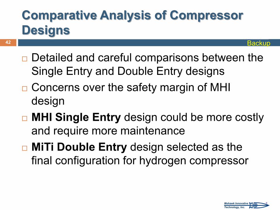
Detailed and careful comparisons between the Single Entry and Double Entry designs
Concerns over the safety margin of MHI design
MHI Single Entry design could be more costly and require more maintenance
MiTi Double Entry design selected as the final configuration for hydrogen compressor
42
Comparative Analysis of Compressor Designs
Backup
®Mohawk InnovativeTechnology, Inc.
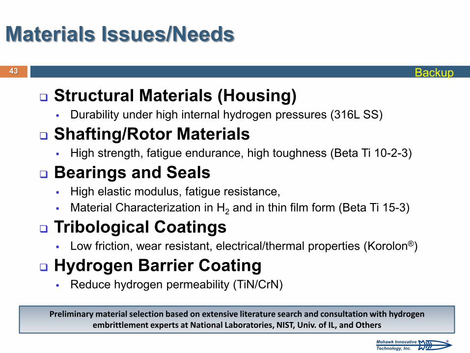
Structural Materials (Housing) Durability under high internal hydrogen pressures (316L SS)
Shafting/Rotor Materials High strength, fatigue endurance, high toughness (Beta Ti 10-2-3)
Bearings and Seals High elastic modulus, fatigue resistance, Material Characterization in H2 and in thin film form (Beta Ti 15-3)
Tribological Coatings Low friction, wear resistant, electrical/thermal properties (Korolon®)
Hydrogen Barrier Coating Reduce hydrogen permeability (TiN/CrN)
43
Materials Issues/Needs
Preliminary material selection based on extensive literature search and consultation with hydrogen embrittlement experts at National Laboratories, NIST, Univ. of IL, and Others
Backup
®Mohawk InnovativeTechnology, Inc.
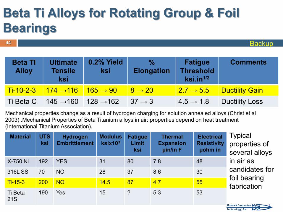
Beta Ti Alloys for Rotating Group & Foil Bearings
44
Beta TI Alloy
Ultimate Tensile
ksi
0.2% Yield ksi
% Elongation
Fatigue Threshold
ksi.in1/2
Comments
Ti-10-2-3 174 →116 165 → 90 8 → 20 2.7 → 5.5 Ductility Gain
Ti Beta C 145 →160 128 →162 37 → 3 4.5 → 1.8 Ductility Loss
Mechanical properties change as a result of hydrogen charging for solution annealed alloys (Christ et al 2003) .Mechanical Properties of Beta Titanium alloys in air: properties depend on heat treatment (International Titanium Association).
Material UTS ksi
Hydrogen Embrittlement
Modulus ksix103
Fatigue Limit ksi
Thermal Expansion
µin/in F
Electrical Resistivity
µohm in
X-750 Ni 192 YES 31 80 7.8 48
316L SS 70 NO 28 37 8.6 30
Ti-15-3 200 NO 14.5 87 4.7 55
Ti Beta 21S
190 Yes 15 ? 5.3 53
Typical properties of several alloys in air as candidates for foil bearing fabrication
Backup
®Mohawk InnovativeTechnology, Inc.
45
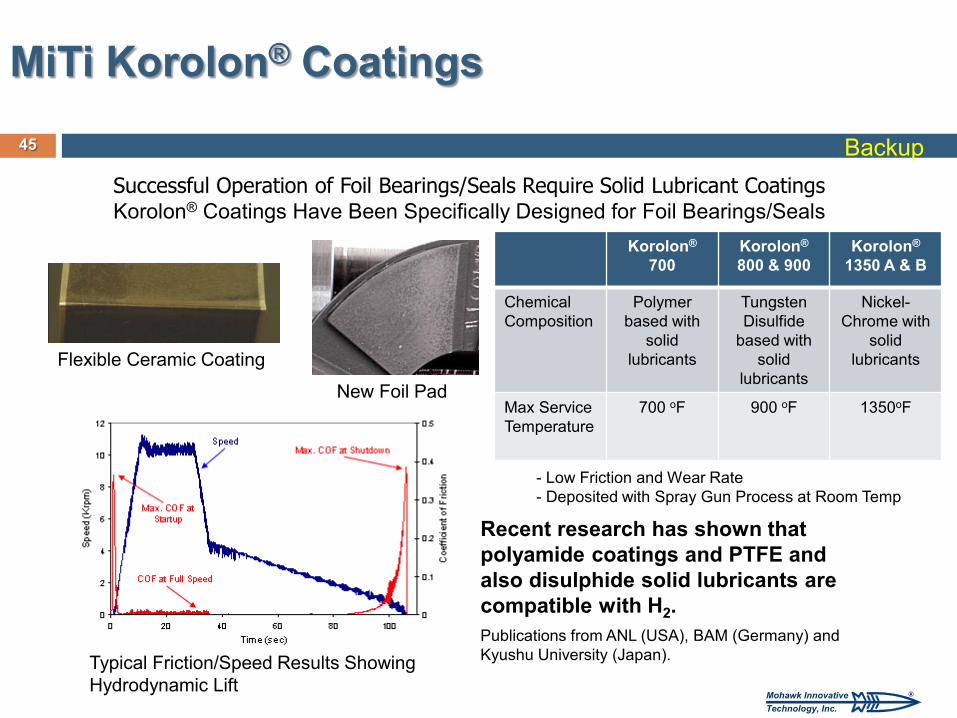
MiTi Korolon® Coatings
Successful Operation of Foil Bearings/Seals Require Solid Lubricant Coatings Korolon® Coatings Have Been Specifically Designed for Foil Bearings/Seals
Recent research has shown that polyamide coatings and PTFE and also disulphide solid lubricants are compatible with H2. Publications from ANL (USA), BAM (Germany) and Kyushu University (Japan).
New Foil Pad
Flexible Ceramic Coating
Typical Friction/Speed Results Showing Hydrodynamic Lift
Korolon® 700
Korolon® 800 & 900
Korolon® 1350 A & B
Chemical Composition
Polymer based with
solid lubricants
Tungsten Disulfide
based with solid
lubricants
Nickel-Chrome with
solid lubricants
Max Service Temperature
700 oF 900 oF 1350oF
- Low Friction and Wear Rate - Deposited with Spray Gun Process at Room Temp
Backup