Embed Size (px)
Citation preview

GRUNDFOS DATA BOOKLET
CR, CRI, CRNCustom-built pumps
50/60 Hz

2
Contents
General dataCustom-built pumps 3Variant overview 3Performance range, 50 and 60 Hz 4Type keys 5Codes 5How to read a curve chart 6Curve conditions 6
MotorsGeneral information 7Explosion-proof motors 7Low-noise motors 7Motors with multi-plug connection 7Efficiency class 1 motors 8Motors with thermal protection 9
Shaft seal arrangementsDouble seal (tandem) 11Double seal (back-to-back) 12Back-to-back double seal with pressure intensifier 13Back-to-back double seal with dosing pump 13Air-cooled top (high temperatures) 14
Shaft sealsShaft seal with FFKM or FXM O-ring material 16Hybrid shaft seal 17
CertificatesCertificates 18ATEX-approved CR pumps 19
MAGdriveMagnetic-drive pump (MAGdrive) 20
LiqTecLiqTec dry-running sensor 21
PumpsHorizontally mounted pumps 22Pumps with bearing flange 24Belt-driven pumps 26Pumps for liquid temperatures down to –40°C 28Carbon-free pumps 29Silicon-free pumps 29Pumps for pharmaceutical andbiotechnological applications 30TriClamp 30Cleaned and dried pumps 31Electropolished pumps 31
Low-NPSH pumpsLow-NPSH pumps 3350 HZ, curves and data 3460 Hz, curves and data 50
4-pole versionsCR pumps with 4-pole motors 6650 HZ, curves 6760 HZ, curves 77

Custom-built pumps
General dataCustom-built pumpsGrundfos offers a wide range of custom-built variants ofthe CR type range for a variety of demanding industrialapplications.
Featuring superior reliability like the standard products,the custom-built pumps meet the strictest demands forrobustness and trouble-free operation.
With these multistage in-line pumps, based on the well-known CR type range, Grundfos meets the customers’needs for pumps capable of handling
• high-temperature liquids
• high-viscosity liquids such as paints and varnishes
• volatile and explosive liquids and
• aggressive liquids
• special installation requirements.
The Grundfos CR range
Material versions:
• Cast iron/stainless steel, W.-Nr. 1.4301 = CR
• Stainless steel, W.-Nr. 1.4301 = CRI
• Stainless steel, W.-Nr. 1.4401 = CRN
• Titanium = CRT
Pump types:
CR 1s, 1, 3, 5, 10, 15, 20, 32, 45, 64 and 90.
Pumped liquid temperature:
–40°C to +180°C.
This data booklet gives an overview of some of thecustom-built solutions offered by Grundfos.
If the data booklet does not provide a solution to yourspecific pumping needs, please contact your localGrundfos company with a detailed description of yourproblem, and we shall get down to work - for you!
Variant overviewThe overview of custom-built solutions refers only tothe CR, CRI, CRN range.
The overview is divided into the following parts:
• Motors
• Shaft seals
• Pumps.
Motors
The standard range of motors meets a wide variety ofapplication demands.
For special applications or operating conditions,Grundfos offers custom-built motors such as
• explosion-proof motors for hazardous atmospheres (ATEX approved motors)
• motors with anti-condensation heating unit for hu-mid environments
• efficiency class 1 motors
• low-noise motors
• motors with multi-plug connection
• motors with thermal protection.
Shaft seals
Grundfos offers a wide range of special-purpose shaftseals and shaft seal arrangements for the pumping ofliquids such as
• aggressive or corrosive liquids
• particle-carrying liquids
• toxic or explosive liquids
• high-viscosity or sticky liquids
and for operating under conditions such as
• extremely high pressures
• extremely high or low temperatures.
Pumps
The pump can be custom-built for special operatingconditions and applications such as
• high inlet pressures
• high-pressure systems up to 50 bar
• horizontal mounting
• applications demanding belt-driven pumps
• pharmaceutical and biotechnological applications
• applications requiring low NPSH.
GR5
357
3

4
General data Custo
m-built pumpsPerformance range, 50 and 60 Hz
TM0
2 11
92
250
3
10.8 11 2 3 4 5 6 8 1010 20 30 40 50 60 80 100100 Q [m³/h]
20
30
40
60
80
100
200
300
400
H[m] 50 Hz
CR 1
CR 3
CR 5
CRI 1
CRN 1
CRI 3
CRN 3
CRI 5
CRN 5
CRN 32
CRN 64
CRN 90CRN 45
CR 32
CR 45
CR 64
CR 90
CR 10
CRI 10
CRN 10
CR 15
CRI 15
CRN 15
CR 20
CRI 20
CRN 20
CR 1s
CRI 1s
CRN 1s
10.8 11 2 3 4 5 6 8 1010 20 30 40 50 60 80 100100 Q [m³/h]
0
20
40
60
80
[%]Eta
High-pressure range
TM0
2 15
30 2
803
10.8 11 2 3 4 5 6 8 1010 20 30 40 50 60 80 100100 Q [m³/h]
20
30
40
60
80
100
200
300
400
H[m] 60 Hz
CR 1s CR 10
CR 15
CR 20
CR 1
CR 90
CR 64
CR 45
CR 32CR 5
CR 3
CRI 1CRN 1
CRI 3
CRN 3
CRI 5CRN 5
CRN 32 CRN 64
CRN 90CRN 45CRI 10
CRN 10
CRI 15CRN 15
CRI
CRN
20
20
CRI 1s
CRN 1s
10.8 11 2 3 4 5 6 8 1010 20 30 40 50 60 80 100100 Q [m³/h]
0
20
40
60
80[%]Eta
High-pressure range

General data Custom
-built pumpsType keysCR(E), CRI(E), CRN(E)
Codes
Example CR E 32 s -4 -2 -A -F -G -E -HQQE
Type range:CR, CRI, CRN
Pump with integrated frequency control
Flow rate [m3/h]
Under size impeller (all impellers)- only for CR 1s, CRI 1s, CRN 1s
Number of impellers
Number of reduced-diameter impellers CR,N(E) 32, 45, 64, 90
Code for pump version
Code for pipe connection
Code for materials
Code for rubber parts
Code for shaft seal
Example A -F -A -E -H QQ E
Pump version
A Basic version
B Oversize motor
E Cetificate/approval
FCR pump for high temperatures(air-cooled top assembly)
H Horizontal version
HSHigh-pressure pump with high speed MGE motor
I Different pressure rating
J Pump w/different max speed
K Pump with low NPSH
M Magnetic drive
N Fitted with sensor
P Undersize motor
R Horizontal version with bearing bracket
SF High pressure pump
TOver size motor(two flange sizes bigger)
X Special version
Pipe connection
A Oval flange
B NPT thread
CA FlexiClamp (CRI(E), CRN(E) 1, 3, 5, 10, 15, 20)
CX Triclamp (CRI(E), CRN(E) 1, 3, 5, 10, 15, 20)
F DIN flange
G ANSI flange
J JIS flange
N Changed diameter of ports
P PJE coupling
X Special version
Materials
A Basic version
D Carbon-graphite filled PTFE (bearings)
G Wetted parts 1.4401/AISI 316
GIAll parts stainless steel, wetted parts 1.4401/AISI 316
I Wetted parts 1.4301/AISI 304
IIAll parts stainless steel, wetted parts 1.4301/AISI 304
K Bronze (bearings)
S SiC bearings + PTFE neck rings
X Special version
Code for rubber parts
E EPDM
F FXM
K FFKM
P NBR
T PTFE
V FKM
Shaft seal
A O-ring seal with fixed driver
B Rubber bellows seal
C O-ring seal with spring as seal driver
D O-ring seal, balanced
E Cartridge seal with O-ring
F Cartridge seal with rubber bellows
H Balanced cartridge seal with O-ring
K Type M as cartridge seal
M Shaft seal with metal bellows
O Double seal, back-to-back
P Double seal, tandem
R O-ring seal, type A, with reduced sliding surfaces
X Special version
B Carbon, synthetic resin-impregnated
C Other types of carbon
S Chromium steel
H Cemented tungsten carbide, embedded (hybrid)
U Cemented tungsten carbide
V Aluminium oxide
Q Silicon carbide
X Other ceramics
E EPDM
F FXM
K FFKM
P NBR (nitrile rubber)
T PTFE
V FKM
Example A -F -A -E -H QQ E
5

6
General data Custo
m-built pumpsHow to read a curve chart
Curve conditionsThe guidelines below apply to the curves shown in thisdata booklet.
1. Tolerances to ISO 9906, Annex A, if indicated.
2. The motors used for the measurements arestandard Grundfos motors.
3. Measurements have been made with airless water at a temperature of 20°C.
4. The curves apply to a kinematic viscosity ofυ = 1 mm2/s (1 cSt).
5. Due to the risk of overheating, the pumps shouldnot be used at a flow below the minimum flow rate.
The curve below shows the minimum flow rate as apercentage of the nominal flow rate in relation to theliquid temperature.
The dotted curve represents a pump fitted with an air-cooled top.
TM0
1 31
22 0
303
0 4 8 12 16 20 24 28 32 36 Q [m³/h]
0
5
10
15
20
25
30
35
40
45
50
55
60
H[m]
0 2 4 6 8 10 Q [l/s]
0
100
200
300
400
500
600
[kPa]p
CR 3250 Hz
ISO 9906 Annex A
-2
-2-2
0 4 8 12 16 20 24 28 32 36 Q [m³/h]
0.00.51.01.52.0
P2[kW]
020406080[%]Eta
0
1
2
[hp]P2
Eta1/12/3
0 4 8 12 16 20 24 28 32 36 Q [m³/h]
0102030
[m]H
0246
NPSH[m]
0100200
[kPa]p
NPSHQH 2900 rpm 1/1
QH 2900 rpm 2/3
QH curves for each individual impeller. The chart shows curves for full-diameter (1/1) and reduced-diameter (2/3) impellers.
Number of stagesFirst figure indicates number of stages, second figure indicates number of reduced-diameter impellers.
The power curves indicatepump input power per stage.Chart shows curve for pump with full-diameter impeller (1/1) and reduced-diameter impeller(2/3).
Pump type and frequency
QH curves for the individual pumps.The bold curves indicate the recom-mended performance range for bestefficiency.The thin curves are only to be used as a guide.
The eta curve shows pump effi-ciency. The efficiency of pumps with reduced-diameter impellers is approx. 2% lower than the eta curve shown in the chart.
The NPSH curve is an averagecurve for all the variants shown.When sizing the pumps, add asafety margin of at least 0.5 m.
TM0
1 28
16 0
303
40 60 80 100 120 140 160 180 t [°C]
0
10
20
30
Qmin[%]

Custom-built pumps
MotorsGeneral informationThe Grundfos standard range of motors meets a widevariety of application demands. For special applicationsor operating conditions, Grundfos offers custom-builtmotors such as
• explosion-proof motors
• motors with anti-condensation heating unit
• low-noise motors
• motors with multi-plug connection
• efficiency class 1 motors
• motors with thermal protection.
Explosion-proof motorsGrundfos offers explosion-proof or dust-ignition-proofmotors. Grundfos can supply ATEX approved motors in 2G EExe IIT3 , 2G EExd IIB T4, EEx 2D T125° and EEx 3D T125° version.All Explosion-proof motors has angular contact bearingsand PTC.
VEM 2G EExe II T3 is only available up to 28 kW as EExemotors are derated.
Reference numbers
Motors with anti-condensation heating unitHigh humidity may cause condensation in the motor.Slow condensation occurs as a result of low temperatureat night; rapid condensation occurs as a result of shockcooling caused by direct sun followed by tropical rain.
Designed to IP 65, Grundfos motors are capable of oper-ating continuously in applications with up to 85%humidity and temperatures up to 25°C and short-time upto 95% humidity at temperatures up to 40°C.
In applications with constantly high humidity levels above85%, the drain holes in the drive-end flange should beopen. This changes the motor protection level to IP 44.
If IP 55 protection is required due to operation in dusty envi-ronments, it is recommended to fit an anti-condensationheating unit on the stator coil ends.
The heating unit keeps the motor temperature constantduring nights and prevents condensation.
Grundfos motor types available with anti-condensationheating unit:
1 x 220-250 V, 50 or 60 Hz
Reference numbers
Low-noise motorsGrundfos offers low-noise Siemens motors with a noiselevel 7-8 dB below that of standard motors.
Note: The 15 kW and 18.5 kW standard motors for the CRseries are low-noise types.
Reference numbers
Motors with multi-plug connectionMotors fitted with a multi-plug connection (Harting®
plug) enable easy connection to the mains.
The drawing below shows examples of different multi-plug positions.
Reference numbers
Motor [kW]
BrandReference
numberVEM CEMP VEM
(2G EExe II T3) (2G EExd IIB T4) (2D T125°) (3D T125°)
0.37 - 1.3 98 99 41
1.85 - 4.6 98 99 40
5.5 - 7.5 98 99 39
10 - 15 98 98 52
0.37 - 1.5 98 99 38
2.2 - 4.0 98 99 37
5.5 - 7.5 98 99 36
9.2 - 11 98 98 76
15 - 45 98 98 51
0.37 - 45 98 96 12
0.37 - 45 98 96 13
Motor type Power of heating unit [W]
MG 71 - MG 100 23
MG 121 - MG 132 31
MG 160 38
Motor [kW] Reference number
0.37 - 11 98 97 78
Motor [kW] Reference number
Up to 22 98 98 39
30 - 37 98 98 38
45 98 98 37
TM0
1 87
15 0
700
- TM
02
4922
180
2
Motor [kW] Reference number
0.25 - 7.5 kW 98 97 86
7

8
Motors Custo
m-built pumpsEfficiency class 1 motors
General information
Grundfos offers motors in the highest European effi-ciency class, EFF 1. The motors are classified under theEU/CEMEP motor efficiency labelling scheme.
Benefits offered by EFF 1 labelled motors
• Improved efficiency (see the graph below)
• Lower noise level
• Higher permissible ambient temperature
• Longer bearing life due to reduced temperature.
Pump range
EFF 1 motors are available for the following Grundfospumps:
The graph below shows the efficiency level of the EFF 1and EFF 2 classified Grundfos motors within the EU/CEMEP defined efficiency bands.
EFF 1 motors meet the following efficiency levels:
Reference numbers
Calculation example showing energy savings of a high-efficiency motor:
Esaving = Energy savings per year
P2 = Nominal power output (4.0 kW)
toperating = Operating time (2,500 h/year)
Pload = Percentage of full load (90%)
ηnew = Efficiency of new motor (0.89)
ηold = Efficiency of old motor (0.86)
Esaving = P2 x Pload x toperating x (1/ηold – 1/ηnew)
Example:
Esaving = 4.0 x 0.90 x 2,500 x (1/0.86 – 1/0.89) = 353 kWh/year.
Pump type
CR 1s CR 1 CR 3 CR 5 CR 10 CR 15 CR 20 CR 32 CR 45 CR 64 CR 90
CR
CRI
CRN
TM0
2 70
26 2
303
0 1 2 3 4 5 6 7 8 9 10 11 12 13 14 15 16P2 [kW]
76
78
80
82
84
86
88
90
92
94
[%]
Siemens
MMG-E
MMG-D
MG-D
MG-C
Eff3 2 p
Eff2 2 p
Eff1 2 p
1.1 1.5 2.2 5.5 7.5 11 15 18.5 22 30 4537 55 75 90
Motor[kW]
Minimumefficiency
Motor[kW]
Minimumefficiency
1.1 82.8 11 90.5
1.5 84.1 15 91.3
2.2 85.6 18.5 91.8
3 86.7 22 92.2
4 87.6 30 92.9
5.5 88.6 37 93.3
7.5 89.5 45 93.7
Motor [kW] Reference number
1.1 - 3.0 98 97 23
4.0 98 97 22
5.5 98 97 21
7.5 - 15 98 97 20
18.5 98 97 19
22 98 97 18
30 98 97 17
37 98 97 16
45 98 97 15

Motors Custom
-built pumpsMotors with thermal protectionGrundfos offers motors with built-in bimetallic thermalswitches or temperature-controlled PTC sensors (ther-mistors) incorporated in the motor windings.
Grundfos motors from 3 kW and up have PTC sensors(thermistors) as standard.
Thermal switches
Examples of trade names are Klixon® and Thermik.
The thermal switches must be connected to an externalcontrol circuit to protect the motor against slow over-heating. The thermal switches require no tripping unit.
Protection according to IEC 34-11: TP 111 (slow over-heating). As protection against seizure, the motor mustbe connected to a motor starter.
Thermal switches tolerate the following maximumloads:
Umax = 250 VACIn = 1.5 AImax = 5.0 A (locked-rotor and breaking current).
The figure below shows an example of a typical circuit ofa three-phase motor with built-in bimetallic thermalswitches.
Key to figure:
TM0
0 3
96
4 14
94
S1 On/off switch
K1 Contactor
t° Thermal switch in motor
M Motor
MV Motor starter
9

10
Motors Custo
m-built pumpsPTC sensors (thermistors)
To protect the motor against rapid as well as slow over-heating, the temperature-controlled PTC sensors (ther-mistors) must be connected to an external tripping orLiqTec™ unit connected to the control circuit.
Protection according to IEC 34-11: TP 211 (slow over-heating and seizure).
Thermistors comply with DIN 44 082. Maximum voltageat the terminals: Umax = 2.5 VDC. All tripping units avail-able for DIN 44 082 thermistors meet this requirement.
The figure below shows an example of a typical circuit ofa three-phase motor with PTC sensors (thermistors):
Key to figure:
Reference numbers
TM0
0 3
96
5 14
94
L1 L2 L3 N
K1
M3
N
3UN2 100-0 C
9896A2T2T1
K1
S1
KH2
95A1
H1
S1 On/off switch
K1 Contactor
+T PTC sensor (thermistor) in motor
M Motor
3UN2 100-0 C Tripping unit with automatic reset
N Amplifier
K Output relay
H1 LED ‘Ready’
H2 LED ‘Tripped’
A1, A2 Connection for control voltage
T1, T2 Connection for PTC sensor loop
Protection Reference number
Built-in bimetallic thermal switch (TP 111) 98 99 91
Built-in PTC sensor (thermistor) (TP 211)for motors below 3 kW
98 99 35

Custom-built pumps
Shaft seal arrangementsDouble seal (tandem)
General information
Double seals mounted in tandem are recommended foruse with crystallizing, hardening or sticky liquids.
Reference applications
• Pharmaceutical industry (production of dextran)
• Negative pressure deaeration systems (vacuum)
• Industries handling potentially hardening oilproducts
• Caustic soda (sodium hydroxide - NaOH)
• Hydrated lime (calcium hydroxide - Ca(OH)2).
Pump range
The tandem type of seal is available for the followingGrundfos pumps:
Technical description
This type of double seal consists of two shaft sealsmounted in a tandem arrangement in a separate sealchamber. Only Grundfos cartridge shaft seals can beused.
If the primary seal is leaking, the pumped liquid will beflushed away by the flushing liquid.
The flushing liquid pressure must always be lower thanthe pumped liquid pressure.
Recommended flushing liquid conditions:
• Q = 25-200 l/hour
• p = 4-6 bar
Sectional drawings
CR, CRI, CRN 1, 3 and 5
CR, CRI, CRN 10, 15 and 20
CR, CRN 32, 45, 64 and 90
Dimensions
Reference numbers
Pump type
CR 1s CR 1 CR 3 CR 5 CR 10 CR 15 CR 20 CR 32 CR 45 CR 64 CR 90
CR
CRI
CRN
TM0
2 21
39 3
701
TM0
2 73
86 3
403
TM0
1 6
204
169
9
Pump typeAdditional height of seal chamber *
[mm]
CR, CRI, CRN 1, 3 and 5 108
CR, CRI, CRN 10, 15 and 20 90
CR, CRN 32, 45, 64 and 90 0
* As compared to a standard pump.
Pump type Reference number
CR, CRI, CRN 1, 3 and 5 98 97 08
CR, CRI, CRN 10, 15 and 20 98 94 70
CR, CRN 32, 45, 64 and 90 98 98 05
Outlet ½"
Inlet ½"
•
• •
•
Inlet 3/8"Outlet 3/8"
Outlet ½"
Inlet ½"
11
12
Shaft seal arrangements Custo
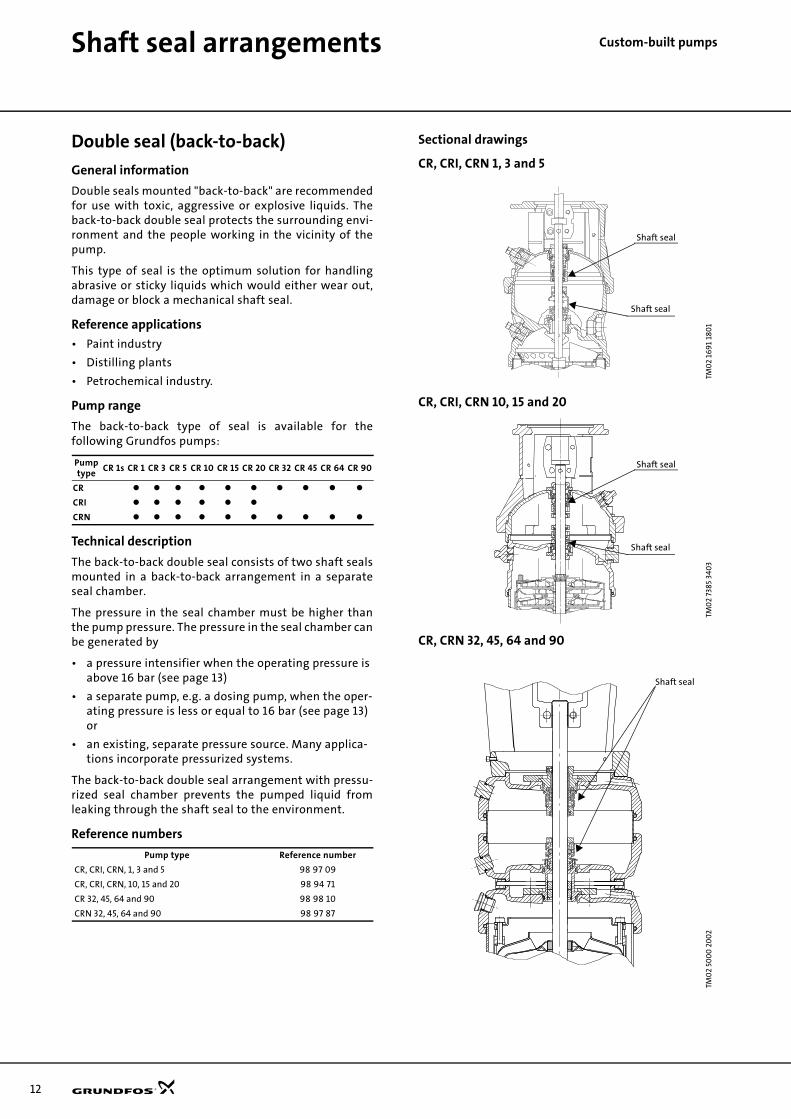
m-built pumpsDouble seal (back-to-back)
General information
Double seals mounted "back-to-back" are recommendedfor use with toxic, aggressive or explosive liquids. Theback-to-back double seal protects the surrounding envi-ronment and the people working in the vicinity of thepump.
This type of seal is the optimum solution for handlingabrasive or sticky liquids which would either wear out,damage or block a mechanical shaft seal.
Reference applications
• Paint industry
• Distilling plants
• Petrochemical industry.
Pump range
The back-to-back type of seal is available for thefollowing Grundfos pumps:
Technical description
The back-to-back double seal consists of two shaft sealsmounted in a back-to-back arrangement in a separateseal chamber.
The pressure in the seal chamber must be higher thanthe pump pressure. The pressure in the seal chamber canbe generated by
• a pressure intensifier when the operating pressure is above 16 bar (see page 13)
• a separate pump, e.g. a dosing pump, when the oper-ating pressure is less or equal to 16 bar (see page 13) or
• an existing, separate pressure source. Many applica-tions incorporate pressurized systems.
The back-to-back double seal arrangement with pressu-rized seal chamber prevents the pumped liquid fromleaking through the shaft seal to the environment.
Reference numbers
Sectional drawings
CR, CRI, CRN 1, 3 and 5
CR, CRI, CRN 10, 15 and 20
CR, CRN 32, 45, 64 and 90
Pump type
CR 1s CR 1 CR 3 CR 5 CR 10 CR 15 CR 20 CR 32 CR 45 CR 64 CR 90
CR
CRI
CRN
Pump type Reference number
CR, CRI, CRN, 1, 3 and 5 98 97 09
CR, CRI, CRN, 10, 15 and 20 98 94 71
CR 32, 45, 64 and 90 98 98 10
CRN 32, 45, 64 and 90 98 97 87
TM0
2 16
91
180
1TM
02
7385
340
3TM
02
500
0 2
00
2
Shaft seal
Shaft seal
Shaft seal
Shaft seal
•
Shaft seal
Shaft seal arrangements Custom
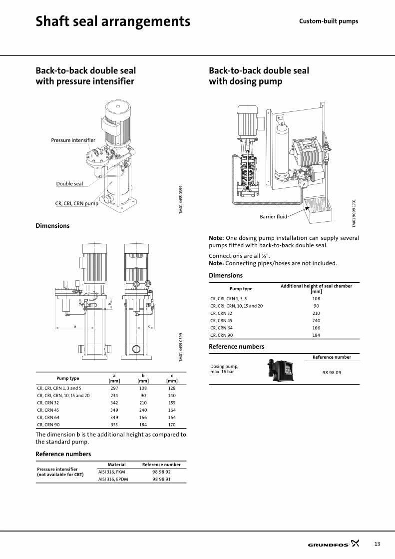
-built pumpsBack-to-back double seal with pressure intensifier
Dimensions
The dimension b is the additional height as compared tothe standard pump.
Reference numbers
Back-to-back double seal with dosing pump
Note: One dosing pump installation can supply severalpumps fitted with back-to-back double seal.
Connections are all ½".Note: Connecting pipes/hoses are not included.
Dimensions
Reference numbers
TM0
1 44
55 0
399
TM0
1 44
59 0
399
Pump typea
[mm]b
[mm]c
[mm]
CR, CRI, CRN 1, 3 and 5 297 108 128
CR, CRI, CRN, 10, 15 and 20 234 90 140
CR, CRN 32 342 210 155
CR, CRN 45 349 240 164
CR, CRN 64 349 166 164
CR, CRN 90 355 184 170
Pressure intensifier(not available for CRT)
Material Reference number
AISI 316, FKM 98 98 92
AISI 316, EPDM 98 98 91
CR, CRI, CRN pump
Double seal
Pressure intensifier
a
b
c
TM0
1 9
09
9 1
701
Pump typeAdditional height of seal chamber
[mm]
CR, CRI, CRN 1, 3, 5 108
CR, CRI, CRN, 10, 15 and 20 90
CR, CRN 32 210
CR, CRN 45 240
CR, CRN 64 166
CR, CRN 90 184
Dosing pump,max. 16 bar
Reference number
98 98 09
Barrier fluid
13

14
Shaft seal arrangements Custo
m-built pumpsAir-cooled top (high temperatures)
General information
The unique Grundfos air-cooled top shaft seal solution isrecommended for applications involving high tempera-tures from 120°C to 180°C.
The following air-cooled top solutions are available:
• 120-150°C - EPDM rubber parts
• 120-180°C - FXM rubber parts.
Reference applications
• Boiler feeding
• Temperature control, e.g. in moulding processes
• Circulation of transmission oils.
Pump range
The air-cooled top is available for the followingGrundfos pumps:
120-150°C and 120-180°C
Technical description
The air-cooled top separates the seal chamber from thepump by an air-cooled chamber, generating an insu-lating effect similar to that of a thermos.
Via the narrow passage between the pump and the air-cooled top, a small quantity of the pumped liquid recir-culates by natural circulation.
Temperatures above 120°C normally result in a substan-tial reduction of seal life due to poor lubrication of theseal faces.
As the temperature in the seal chamber does not exceed120°C during operation, a standard Grundfos shaft sealcan be used.
The Grundfos air-cooled top does not require anyexternal cooling.
An automatic air vent is required to vent the pump sealchamber.
Air-cooled top with bearing flange
For applications involving pumping of water up to180°C, the pump requires a net positive inlet pressure,according to the vapour pressure of water.
To prevent the axial thrust generated by the inlet pres-sure from being transmitted to the motor shaft andbearings, a bearing flange is fitted between pump andmotor.
A bearing flange is incorporated in the followingGrundfos pump types:
The max. permissible operating pressure of pumps withair-cooled top for temperatures up to 180°C is 25 bar.
Dimensions
Reference numbers, air-cooled top for 120-150°C
Reference numbers, air-cooled top for 120-180°C
GR5
228
Pump type
CR 1s CR 1 CR 3 CR 5 CR 10 CR 15 CR 20 CR 32 CR 45 CR 64 CR 90
CR
CRI
CRN
50 Hz 60 Hz
CRI, CRN 10-1 --> 10-6 CRI, CRN 10-1 --> 10-5
CRI, CRN 15-1 --> 15-3 CRI, CRN 15-1 --> 15-2
CRI, CRN 20-1 --> 20-3 CRI, CRN 20-1
CR,CRN 32-1-1 --> 32-4 CR,CRN 32-1-1 --> 32-2
CR, CRN 45-1-1 --> 45-2 CR, CRN 45-1-1 --> 45-1
CR, CRN 64-1-1 --> 64-2-2 CR, CRN 64-1-1 --> 64-2-1
CR, CRN 90-1-1 --> 90-1 CR, CRN 90-1-1 --> 90-2-2
Pump typeAdditional pump height
[mm]
CRI, CRN 1, 3 and 5 108
CRI, CRN 10, 15 and 20 90
CR, CRN 32 210
CR, CRN 45 240
CR, CRN 64 166
CR, CRN 90 184
Pump type Reference number
CRI, CRN 1, 3 and 5 98 97 10
CRI, CRN, 10, 15 and 20 98 94 72
CR 32, 45, 64 and 90 98 98 46
CRN 32 and 45 98 98 44
CRN 64 and 90 98 98 43
Pump type Reference number
CRI, CRN 1, 3 and 5 98 96 40
CRI, CRN, 10, 15 and 20 98 94 73
CR 32, 45, 64 and 90 98 96 38
CRN 32 and 45 98 96 37
CRN 64 and 90 98 96 36

Shaft seal arrangements Custom
-built pumpsSectional drawings
CRI, CRN 1, 3 and 5 CRI, CRN 10, 15 and 20
CR, CRN 32, 45, 64 and 90
TM0
2 16
93
180
1
Liquid
Air chamberPipe
Shaft seal
Air vent
TM0
2 73
84 3
403
TM0
1 47
85 0
899
Air vent
Liquid
Air chamber
Shaft seal
1/2"
Bush
••
• •
•
•
•
•
•
Air vent
Liquid
Air
Pipe
Bush
chamber
Shaft seal
1/2"
15
16
Custom-built pumps
Shaft sealsShaft seals
General information
Liquids or applications exceeding the range of normaloperating conditions require special-purpose shaft sealsolutions.
To ensure reliability and avoid untimely breakdowns,the following conditions must be considered:
• temperature,
• pressure
• pumped liquid.
In order to meet any specific requirements, Grundfosoffers the following variants:
1. Shaft seals with FFKM or FXM O-ring material
2. Hybrid shaft seals
Recommended operating range
The actual operating range of the shaft seal depends onthe operating pressure, pump type, type of shaft sealand liquid temperature. The following table applies toclean water and water containing glycol.
For explanation of codes, see the type key on page 5.
*Maximum operation temperature is 120°C for thestandard range.
Pumps equipped with an air cooled top the maximumoperation temperature is 180°C.
Shaft seal with FFKM or FXM O-ring material
General information
Shaft seals with FFKM or FXM O-ring material are recom-mended for applications where the pumped liquids maydamage the standard O-ring material.
See the list of pumped liquids in the CR, CRI, CRN databooklet.
Reference applications, FFKM (Kalrez®)
• Chemical industry (aggressive liquids)
• Petrochemical industry (oils)
• High-temperature applications.
Plug and sleeve O-rings made of FFKM are also availablefor CR, CRI, CRN 1s, 1, 3, 5, 10, 15 and 20.
Reference applications, FXM (Flouraz®)
• High-temperature applications (instead of FKM).
Plug and sleeve O-rings made of FXM are available forthe full range.
Pump range
Shaft seals with FFKM or FXM O-ring are available for thefollowing Grundfos pumps:
Technical description
The FFKM and FXM O-rings replace the standard shaftseal O-rings.
Dimensions
Dimensions are identical to those of the standard shaftseal.
Reference numbers
Pump type Shaft sealMin.
temp.Max.temp.
Pressurerating
CR, CRI, CRN1s, 1, 3, 5, 10, 15, 20, 32, 45, 64, and 90
HUBx 0 120 30
HUUx -40 90 30
HQQx -40 120 30
HQBx 0 120 30
Rubber type Min. temperature Max. temperature
EPDM -40 120
FKM -20 90
FXM -10 275*
FFKM -20 275*
Pump type
CR 1s CR 1 CR 3 CR 5 CR 10 CR 15 CR 20 CR 32 CR 45 CR 64 CR 90
FFKM
FXM
Pump typeReference number
FFKM FXM
CR, CRI, CRN 1s, 1, 3 and 5 98 99 72 98 96 78
CR, CRI, CRN 10, 15 and 20 98 94 74 98 94 75
CR, CRN 32, 45, 64 and 90 98 98 15 98 96 77

Shaft seals Custom
-built pumpsHybrid shaft seal
General information
Hybrid shaft seals are recommended for applicationsinvolving a risk of dry running.
Reference applications
• Boiler-feed applications
• Applications involving degassing of liquids
• Industrial applications involving frequent priming.
Pump range
Hybrid shaft seals are available for the followingGrundfos pumps:
Technical description
The stationary seat of the shaft seal is equipped with anextra, special-carbon seal face, expanding at hightemperatures as a result of dry running or similar condi-tions.
This eliminates the usual damaging effects of dryrunning, such as leakage and noise.
Sectional drawing
Dimensions
Dimensions are identical to those of the standard shaftseal.
Reference numbers
Pump type
CR 1s CR 1 CR 3 CR 5 CR 10 CR 15 CR 20 CR 32 CR 45 CR 64 CR 90
CR
CRI
CRN
TM0
2 42
79 0
402
Pump type Reference number
CR, CRN 32, 45, 64 and 90 98 98 01
Hybrid seal design
17

18
Certificates Custo
m-built pumpsCertificates
General information
Grundfos offer a number of certificates for differentpurposes. The following types are available...
• material certificates( certificates stating material components or mate-rial specifications)
• performance certificates(printed test reports guaranteeing and certifiing test data of QH performance, current consumption curves, rpm, etc.)
• authorized test by third party(surveyed performance test)
• ATEX approved CR pumps(according to ATEX-directive 94/9/EC)
The certificates must be ordered with the pump.
Reference applications
• Pharmaceutical industries
• Ships and offshore
• Big contractors
• Areas exposed to explosive atmosphere
Pump range
Certificates are available for the following pump types:
GR
5381
Pump type
CR 1s CR 1 CR 3 CR 5 CR 10 CR 15 CR 20 CR 32 CR 45 CR 64 CR 90
CR
CRI
CRN
Certificate Standard
Material specification report
Material report with certificate
ReportATEX-approved pump
Inspection certificate EN 10.204 3.1.B
Inspection certificate- Lloyds Register of Shipping (LRS), - Det Norske Veritas (DNV)Germanisher Lloyd (GL), - Bureau Veritas (BV), - Etc.....
EN 10.204 3.1.C
Surface roughness report
Motor test report
Standard test report ISO 9906
Vibration report
Certificate of compliance with the order
EN 10.204 2.1
Test report - non specific inspec-tion and testing
EN 10.204 2.2
ReportCleaned and dried pump
ReportElectro-polished pump
Part no 96 51 22 40/A53123
ATEX-approved pump
Grundfos hereby confirms that the pump mentioned above is manufactured according the specifications mentioned in the “CR, CRI, CRN Custom-built pumps” data booklet. This means the pump is conformity with the ATEX 94/9EEC (ATEX 100) appendix VIII directive as men-tioned in the “ATEX Supplement to installation and operating instructions” supplied with the pump.
GRUNDFOS Date:
Signature:
Name: Dept.:
Customer name Customer order no. Grundfos order no. Pump type Part number Production code Pump serial no. Motor serial no. ATEX approval of pump
Part no 96 50 79 31/A53123
Surface roughness According to ISO 1302
Customer name Customer order no. Grundfos order no. Pump type Part number CRN base part number
The surface roughness is measured as the maximum roughness of the CRN inlet and outlet surface.
B A
Surface Treatment None
Roughnessvalue RA [µm]
Roughnessdegree
Electro-polished 50 N 12 25 N 11 12.5 N 10 Measured values A 6.3 N 9 R max [µm] 3.2 N 8 R A [µm] 1.6 N 7 R Z [µm] 0.8 N 6 0.4 N 5 Measured values A 0.2 N 4 R max [µm] 0.1 N 3 R A [µm] 0.05 N 2 R Z [µm] 0.025 N 1
GRUNDFOSDate:
Signature:
Name:
Dept.:
Part no 96 50 79 32/A53123
Vibration reportAccording to ISO 10816
Measured object Pump type Part number P2 (kW) Frequency (Hz) Number of poles Serial no.
Test conditions Voltage (V) Frequency: (Hz) Flow (m³/h) Head (m)
The pump is floor-mounted on vibration absorbers. For vibration velocity measurement positions, see figure.
Remarks
Result of measurement:
Pos RMS vibration velocity (mm/s)
12 3 4 5 6 7 8 9
Typical zone boundry limits
RMS vibration velocity (mm/s)
Class I Class II
0.28
0.45
0.71
A
1.12
A
1.8B
2.8B
4.5C
7.1C
11.2
18
28
45
DD
The machine classifications are as follows: Class I: Individual parts of engines and machines, integrally connected to the complete machine in its normal operating condition. (Production electrical motors of up to 15 kW are typical examples of machines in this category.)
Class II: Medium-sized machines (typically electrical motors with 15 kW to 75 kW output) without special foundations, rigidly mounted engines or machines (up to 300 kW) on spe-cial foundations.
GRUNDFOSDate: 25-Jun-04
Signature:
Name:
Dept.:

Certificates Custom
-built pumpsATEX-approved CR pumps
General information
The CR pumps can be approved according to EC directive94/9/EC, the so-called ATEX directive.
The pumps can be used in areas (zones) classifiedaccording to the directive 1999/92/EC. In case of doubt,please consult the above-mentioned directives orcontact GRUNDFOS.
ATEX-approved pumps will be supplied with serialnumber, special installation and operating instructionsand a nameplate including the ATEX classification.
An ATEX-approved pump report is available on request.
Scope of ATEX categories for CR pumps
1) Solutions including MAGdrive or double shaft seal.
2) Note: To enable the use of category 3 G CR pumps in zone 1 areas, the minimum requirement is a dry-running protection aprroved for zone 1. The dry-running protection must stop the pumps if the liquid supply ceases.
Group I
Category M2
Underground installations in mines lia-ble to be endangered by explosive gas-ses or combustible dust.
Pumps made of materials that do not create sparks and thus do not constitute any danger of explosion.
CR pumps available CR, CRI, CRN
Motors available None*
* Air or hydraulic motors are not available from Grundfos.
Group II
Category 2 Category 3
Installation areas liable to be endan-gered by explosive atmospheres.
Pumps intended for use in areas in which explosive atmospheres are likely to occur.
Pumps intended for use in areas in whichexplosive atmospheres only rarely occur.
G (gas) D (dust) G (gas) 2) D (dust)
CR pumps available CR, CRI, CRN 1) CR, CRI, CRN, CRT CR, CRI, CRN, CRT CR, CRI, CRN, CRT
Motors availableVEM 2G EEx e IIT3CEMP 2G EEc d IIB T4
VEM 2D 125°CVEM 2G EEx e IIT3CEMP 2G EEc d IIB T4
VEM 3D 125°C
19
20
Custom-built pumpsMAGdrive
Magnetic-drive pump (MAGdrive)
General information
The zero-leakage, custom-built pump with magneticdrive (MAGdrive) is recommended for the pumping ofhazardous or aggressive liquids.
Grundfos MAGdrive protects the surrounding environ-ment and the people working in the vicinity of the pump.
Reference applications
• Chemical industry (aggressive or toxic liquids)
• Petrochemical industry (volatile liquids)
• Pharmaceutical industry.
Pump range
The following Grundfos pumps are available withMAGdrive:
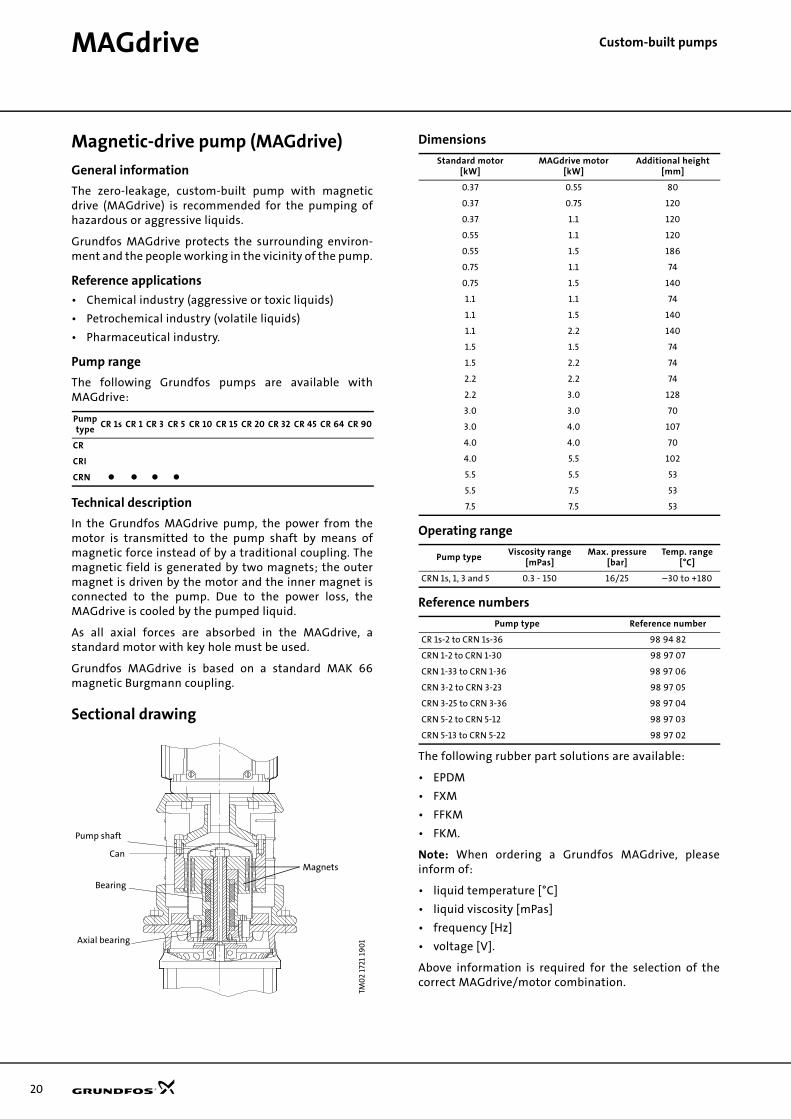
Technical description
In the Grundfos MAGdrive pump, the power from themotor is transmitted to the pump shaft by means ofmagnetic force instead of by a traditional coupling. Themagnetic field is generated by two magnets; the outermagnet is driven by the motor and the inner magnet isconnected to the pump. Due to the power loss, theMAGdrive is cooled by the pumped liquid.
As all axial forces are absorbed in the MAGdrive, astandard motor with key hole must be used.
Grundfos MAGdrive is based on a standard MAK 66magnetic Burgmann coupling.
Sectional drawing
Dimensions
Operating range
Reference numbers
The following rubber part solutions are available:
• EPDM
• FXM
• FFKM
• FKM.
Note: When ordering a Grundfos MAGdrive, pleaseinform of:
• liquid temperature [°C]
• liquid viscosity [mPas]
• frequency [Hz]
• voltage [V].
Above information is required for the selection of thecorrect MAGdrive/motor combination.
Pumptype
CR 1s CR 1 CR 3 CR 5 CR 10 CR 15 CR 20 CR 32 CR 45 CR 64 CR 90
CR
CRI
CRN
TM0
2 17
21 1
90
1
265
250
258
259
Magnets
Pump shaft
Can
Bearing
Axial bearing
Standard motor[kW]
MAGdrive motor[kW]
Additional height[mm]
0.37 0.55 80
0.37 0.75 120
0.37 1.1 120
0.55 1.1 120
0.55 1.5 186
0.75 1.1 74
0.75 1.5 140
1.1 1.1 74
1.1 1.5 140
1.1 2.2 140
1.5 1.5 74
1.5 2.2 74
2.2 2.2 74
2.2 3.0 128
3.0 3.0 70
3.0 4.0 107
4.0 4.0 70
4.0 5.5 102
5.5 5.5 53
5.5 7.5 53
7.5 7.5 53
Pump typeViscosity range
[mPas]Max. pressure
[bar]Temp. range
[°C]
CRN 1s, 1, 3 and 5 0.3 - 150 16/25 –30 to +180
Pump type Reference number
CR 1s-2 to CRN 1s-36 98 94 82
CRN 1-2 to CRN 1-30 98 97 07
CRN 1-33 to CRN 1-36 98 97 06
CRN 3-2 to CRN 3-23 98 97 05
CRN 3-25 to CRN 3-36 98 97 04
CRN 5-2 to CRN 5-12 98 97 03
CRN 5-13 to CRN 5-22 98 97 02

21
Custom-built pumpsLiqTec
LiqTec dry-running sensor
General information
The Grundfos LiqTec dry-running sensor stops the pumpimmediately if
• there is no liquid present in the pump,
• the liquid temperature exceeds 130±5°C.
• the sensor, sensor cable, electronic unit or power supply fails
When connected to the PTC sensors in the motor, theLiqTec also protects the motor against overheating.
The sensor is easily inserted through the pump headclose to the shaft seal.
Reference applications
Any application involving a risk of dry running.
Pump range
The LiqTec is available for the following Grundfospumps:
Technical description
The LiqTec transmits a heat impulse through the sensor,measuring the temperature of the sensor. Liquid in thepump cools the sensor as well as the shaft seal and otherpump parts.
If there is no liquid present, the LiqTec detects a hightemperature in the sensor and cuts out the pump imme-diately to prevent damage. The risk of pump breakdownis thus further reduced by up to 50%.
The LiqTec also prevents excessive liquid temperaturesfrom damaging the pump. If the LiqTec senses a liquidtemperature above 130°C, it cuts out the pump immedi-ately. Further the LiqTec is a failsafe device, meaningthat the pump stops as soon as the sensor detects anerror on the sensor cable, the electronics or if the powersupply of the control unit is cut off.
Restarting after a pump cut-out can be done automati-cally or manually when liquid in the pump is againdetected by the sensor.
Remote restarting is possible via a digital input.
The electronic control unit can also be connected to thepump thermistor measuring the motor temperature. Incase of overheating of the motor, the system cuts outthe pump.
For installation of the Grundfos LiqTec, see the installa-tion example in the right column.
Installation example
Dimensions
116 x 90 mm. The LiqTec can be fitted to a DIN rail to beincorporated in a control cabinet.
Operating range
Reference numbers
TM0
3 0
110
440
4
Pump type
CR 1s CR 1 CR 3 CR 5 CR 10 CR 15 CR 20 CR 32 CR 45 CR 64 CR 90
CR
CRI
CRNTM
03
011
2 40
04
Power supply1 x 80-130 V or1 x 200-240 V
Power consumption 5 W
Max. pressure 40 bar
Min./max. liquid temperature –20°C/120°C
Max. ambient temperature 40°C
Humidity 99%
Pumped liquid Any liquid handled by Grundfos pumps
Cable length 5/15 m
Pump type Reference number
CR, CRI, CRN 1s, 1, 3, 5, 10, 15, 20, 32, 45, 64 and 90 99 96 82
Sensor
3
M
K1
T+
T+
T+
K1
N
L3
L2
L1
Brow
n/Bl
ack
Blu
eW
hit
e
Externalrestart

22
Custom-built pumps
PumpsHorizontally mounted pumps
General information
For safety and space-saving reasons, the pump can bemounted in the horizontal position.
Reference applications
• Ships
• Earthquake areas (low centre of gravity)
• Places with limited access and space.
Pump range
The following Grundfos pumps are available for hori-zontal mounting:
Also available for CRT 2, 4, 8, 16.
Technical description
The pumps are supplied with separate mounting platesfor support of pump and motor.
Note: The following pump types are fitted with a B3 / B5foot/flange mounted motor:
• CR, CRI, CRN 1 to 20 with motors ≥ 7.5 kW and
• CR, CRN 32, 45, 64 and 90.
Reference numbers
Dimensional drawings
CR, CRI, CRN 1s, 1, 3, 5, CR, CRI, CRN 10, 15 and 20 <= 4 kW
CR, CRI, CRN 10, 15 and 20 >=5.5 kW
CR, CRN 32, 45, 64 and 90
GR5
379
Pump type
CR 1s CR 1 CR 3 CR 5 CR 10 CR 15 CR 20 CR 32 CR 45 CR 64 CR 90
CR
CRI
CRN
Pump type Reference number
CR, CRI, CRN 1s, 1, 3 and 5 98 99 51
CR, CRI, CRN 10, 15 and 20 <= 4 kW 98 94 76
CR, CRI, CRN 10, 15 and 20 >= 5.5 kW 98 94 77
CR, CRN 32, 45, 64 and 90 98 98 53
TM0
2 83
72 5
00
3TM
02
8373
50
03
TM0
2 74
26 3
403
L
H
CX
B
B
B1
L
H
X
B
B1
AAAAAA
BB B
4 x ø14
AB
D
8
L
H
X
AAAAAA
BB B
4 x ø19
AB
D
8
256

Pumps Custom
-built pumpsDimensions
CR, CRI, CRN 1s, 1 , 3 and 5, support for base plate and pump head
For pump height B1, see the CR, CRI, CRN data booklet.
CR, CRI, CRN 10, 15 and 20, support for base plate and pump head
For pump height B1, see the CR, CRI, CRN data booklet.
CR, CRI, CRN 10, 15 and 20, support for base plate and motor
CR, CRN 32, 45, 64 and 90, support for base plate and motor
X[mm]
X[mm]
Motor[kW]
B[mm]
H[mm]
L[mm]
C[mm]
Connections
DIN Oval, PJE, FlexiClamp
0.37-0.55
138 140 50
B1-58
105 80
0.75-1.10 B1-64
1.50-2.20 B1-80
3.0-4.0 B1-84
5.5-7.5 B1-114
CR, CRI, CRN 10 CR, CRI, CRN 15/20
X[mm]
X[mm]
Motor[kW]
B[mm]
H[mm]
L[mm]
C[mm]
Connections
DIN, Oval, PJE, Flexiclamp DIN, Oval, PJE, Flexiclamp
0.37-0.55
170 174 50
B1-65
110 1200.75-1.1 B1-69
1.5-2.20 B1-84
3.0-4.0 B1-89
CR, CRI, CRN 10 CR, CRI, CRN 15/20
X[mm]
X[mm]
Motor[kW]
A[mm]
AA[mm]
AAA[mm]
B[mm]
BB[mm]
D[mm]
H[mm]
L[mm]
AB[mm]
Connections
DIN, Oval, PJE, Flexiclamp DIN, Oval, PJE, Flexiclamp
5.5 216 326 366 140 180 68 200 50 276
110 120
7.5 216 326 366 140 180 68 200 50 276
11 254 384 424 210 260 40 200 50 334
15 254 384 424 210 260 40 200 50 334
18.5 254 384 424 254 310 40 200 50 334
CR, CRN 32 CR, CRN 45, 64, 90
X[mm]
X[mm]
Motor[kW]
A[mm]
AA[mm]
AAA[mm]
B[mm]
BB[mm]
D[mm]
AB[mm]
H[mm]
L[mm]
Connection
DIN
1.5 140 320 380 125 165 200 220 290 60
212 177
2.2 140 320 380 125 165 200 220 290 60
3.0 160 340 400 140 180 190 245 290 60
4.0 190 370 430 140 180 178 275 290 60
5.5 216 395 455 140 180 158 300 290 60
7.5 216 395 455 140 180 158 300 290 60
11 254 440 500 210 275 130 340 290 60
15 254 455 515 210 266 130 340 290 60
18.5 254 455 515 254 310 130 340 290 60
22 279 485 545 240 310 110 365 290 60
30 318 540 600 305 365 90 410 290 60
37 318 540 600 305 365 90 410 290 60
45 356 580 640 310 370 65 450 290 60
23

24
Pumps Custo
m-built pumpsPumps with bearing flange
General information
A bearing flange is used in two situations:
• A standard motor with standard ball bearing configu-ration is required: The bearing flange absorbs the hydraulic load from the pump, ensuring an acceptable motor bearing life.
• The pump is required to run at a higher inlet pressure than the maximum pressure recommended:The bearing flange prevents movement of the angu-lar contact bearing in the motor.
Reference applications
High-pressure applications such as
• cleaning
• boiler-feed water treatment
• reverse osmosis.
Pump range
The following Grundfos pumps are available withbearing flange:
Also avaiable for CRT 2, 4, 8, 16.
Technical description
A bearing flange is an additional flange with an oversizeball bearing to absorb axial forces in both directions. Thecoupling is part of the bearing flange fitted in order toobtain optimum alignment.
The bearing flange requires a standard motor withkeyway.
Note: For motor sizes above 11 kW, the bearing flange isequipped with grease nipples and must be lubricatedregularly. Please follow the instructions on the bearingflange.
Sectional drawings
CR, CRI, CRN 1s, 1, 3, 5, <= 5.5 kWCR, CRI, CRN 10, 15 and 20 , <= 4 kW
CR, CRI, CRN 10, 15 and 20, > 4kW
CR, CRN 32, 45, 64 and 90, <= 7.5 kW
TM0
1 43
54 0
199
Pumptype
CR 1s CR 1 CR 3 CR 5 CR 10 CR 15 CR 20 CR 32 CR 45 CR 64 CR 90
CR
CRI
CRN
MG 71- MG 112NEMA 56 C - NEMA 213-5 TC
TM0
2 74
36 3
403
MG 132 - MG 160NEMA 254 TC - NEMA 284 TC
TM0
2 74
37 3
403
MG 100 - MG 132NEMA 182 TC - NEMA 215 TC
TM0
1 43
52 0
199
Pumps Custom
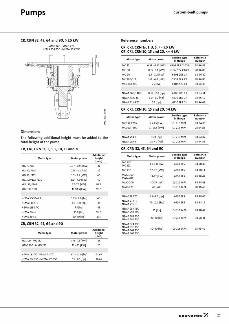
-built pumpsCR, CRN 32, 45, 64 and 90, > 7.5 kW
Dimensions
The following additional height must be added to thetotal height of the pump:
CR, CRI, CRN 1s, 1, 3, 5, 10, 15 and 20
CR, CRN 32, 45, 64 and 90
Reference numbers
CR, CRI, CRN 1s, 1, 3, 5, <= 5.5 kWCR, CRI, CRN 10, 15 and 20, <= 4 kW
CR, CRI, CRN 10, 15 and 20, >4 kW
CR, CRN 32, 45, 64 and 90
MMG 160 - MMG 225NEMA 254 TSC - NEMA 365 TSC
TM0
1 43
53 0
503
Motor type Motor powerAdditional
height[mm]
MG 71, F85 0.37 - 0.55 [kW] 31
MG 80, F100 0.75 - 1.1 [kW] 32
MG 90, F115 1.5 - 2.2 [kW] 40
MG 100/112, F130 3.0 - 4.0 [kW] 40
MG 132, F265 5.5-7.5 [kW] 98.9
MG 160, F300 11-18.5 [kW] 98.9
NEMA 56C/148.2 0.33 - 2.0 [hp] 40
NEMA F182 TC 3.0 - 5.0 [hp] 45
NEMA 213-5 TC 7.5 [hp] 45
NEMA 254-6 15.0 [hp] 98.9
NEMA 284-6 20-40 [hp] 135
Motor type Motor powerAdditional
height[mm]
MG 100 - MG 132 3.0 - 7.5 [kW] 23
MMG 160 - MMG 225 11 - 45 [kW] 20
NEMA 182 TC - NEMA 215 TC 3.0 - 10.0 [hp] 21.65
NEMA 254 TSC - NEMA 365 TSC 15 - 60 [hp] 16.65
Motor type Motor powerBearing type
in flangeReference
number
MG 71 0.37 - 0.55 [kW] 6305 2RS C3/C4 98 96 89
MG 80 0.75 - 1.1 [kW] 6306 2RS. C3/C4 98 96 88
MG 90 1.5 - 2.2 [kW] 6308 2RS C3 98 96 87
MG 100/112 3.0 - 4.0 [kW] 6308 2RS. C3 98 96 86
MG132, F265 5.5 [kW] 6310 2RS. C3 98 96 85
NEMA 56C/148.2 0.33 - 2.0 [hp] 6308 2RS C3 98 96 51
NEMA F182 TC 3.0 - 5.0 [hp] 6310 2RS C3 98 96 50
NEMA 213-5 TC 7.5 [hp] 6310 2RS C3 98 96 49
Motor type Motor powerBearing type
in flangeReference
number
MG132, F265 5.5-7.5 [kW] QJ 216 MPA 98 94 85
MG160, F300 11-18.5 [kW] QJ 216 MPA 98 94 86
NEMA 254-6 15.0 [hp] QJ 216 MPA 98 94 87
NEMA 284-6 20-40 [hp] QJ 216 MPA 98 94 88
Motor type Motor powerBearing type
in flangeReference
number
MG 100MG 112
3.0-4.0 [kW] 6210 2RS 98 98 45
MG 132 5.5-7.5 [kW] 6310 2RS 98 98 14
MMG 160MMG180
11-22 [kW] 6310 2RS 98 98 42
MMG 200 30-37 [kW] QJ 216 MPA 98 98 41
MMG 225 45 [kW] QJ 216 MPA 98 98 40
NEMA 182 TC 3.0-5.0 [hp] 6310 2RS 98 98 45
NEMA 213 TCNEMA 215 TC
7.5-10.0 [hp] 6310 2RS 98 98 14
NEMA 254 TSCNEMA 256 TSC
15 [hp] QJ 216 MPA 98 98 42
NEMA 284 TSCNEMA 286 TSC
20-40 [hp] QJ 216 MPA 98 98 41
NEMA 324 TSCNEMA 326 TSCNEMA 364 TSCNEMA 365 TSC
50-60 [hp] QJ 216 MPA 98 98 40
25

26
Pumps Custo
m-built pumpsBelt-driven pumps
General information
A belt-driven pump is designed to operate in places withlimited space or where no electrical power is available.
Reference applications
Diesel-engine-driven or steam-turbine-driven applica-tions such as:
• applications in remote/distant areas
• mobile applications
• fire protection.
Pump range
The following Grundfos pumps are available as belt-driven pumps:
Also available for CRT 2, 4, 8, 16.
Technical description
An additional bearing has been added on top of anexisting bearing flange. The two bearings are mountedback-to-back. This bearing design makes it possible towithstand the extra radial forces caused by a pulley.
A pulley wheel is attached to the end of the shaft.
By means of pulley belts, the pump can be driven by amotor mounted next to it rather than on top of it.
The pump can be mounted horizontally or vertically byusing the extra support plates.
The pulley head is positioned on the motor stool wherethe motor would normally be fitted. Using the existingholes in the motor stool, the pulley head can be securedto the motor stool with bolts, washers and nuts. Thepulley wheel is then attached to the shaft using anappropriate bush and key.
For extended bearing life, the following pulley wheelsizes are recommended:
GR
5886
Pumptype
CR 1s CR 1 CR 3 CR 5 CR 10 CR 15 CR 20 CR 32 CR 45 CR 64 CR 90
CR
CRI
CRN
Pulley headType III
0.37 - 5.5 kW
Type IV
7.5 - 18.5 kW
Type II
1.5 - 7.5 kW
Type I
11 - 45 kW
Pump typeCR, CRI, CRN
1s, 1, 3, 5,10, 15, 20
CR, CRI, CRN10, 15, 20
CR, CRN 32, 45, 64, 90
Pulley wheel diameter
ø112 - 135 Min. Ø200 Min. ø160 Min. ø200
Number of belts 2 Min. 3 Min. 2 Min. 3
Pump speed [rpm]
Max 3000

Pumps Custom
-built pumpsSectional drawings
CR, CRI, CRN 1s, 1, 3, 5, 10, 15 and 20 (type III)
CR, CRI, CRN 10, 15 and 20 (type IV)
CR, CRN 32, 45, 64 and 90 (type II)
CR, CRN 32, 45, 64 and 90 (type I)
Dimensions
Reference numbers
For horizontal installation, the belt-driven pumps aresupplied with both brackets as standard.
TM0
2 47
83 1
60
2TM
02
7451
350
3TM
02
4785
16
02
TM0
2 47
84 1
60
2
Pump type Pulley headAdditional height
from top of motor stool[mm]
CR, CRI, CRN 1s, 1, 3, 5, 10, 15, 20 Type III 147
CR, CRI, CRN 10, 15, 20 Type IV 310
CR, CRN 32, 45, 64 and 90Type II 123
Type I 148
Pump type Pulley head Reference number
CR, CRI, CRN 1s, 1, 3, 5, 10, 15, 20 Small 98 96 48
CR, CRI, CRN 10, 15, 20 Type II 98 94 89
CR, CRN 32, 45, 64 and 90Type II 98 96 47
Type I 98 96 46
27

28
Pumps Custo
m-built pumpsPumps for liquid temperatures down to –40°C
General information
Grundfos offers pumps suitable for the pumping ofliquids of extreme temperatures down to –40°C.
Reference applications
• Cooling systems with antifreeze and brines
• Ventilation systems
• Industrial processes.
Pump range
The following Grundfos pumps are available for liquidtemperatures down to –40°C:
The standard CRN 32, 45, 64 and 90 pumps fitted withshaft seal type HQQE are capable of operating atliquid temperatures down to –40°C.
Technical description
CRI, CRN 1s, 1, 3, 5, 10, 15 and 20 feature
• PTFE neck rings with inner diameter exceeding stand-ard dimensions.
Please note that pumped liquids containing antifreezeoften require the use of oversize motors due to thehigher viscosity of these liquids.
Dimensions
Dimensions are identical to those of a standard pump.
Reference numbers
GR5
219
Pump type
CR 1s CR 1 CR 3 CR 5 CR 10 CR 15 CR 20 CR 32 CR 45 CR 64 CR 90
CR
CRI
CRN
Pump type Reference number
CRI, CRN 1s, 1, 3 and 5 98 98 75
CRI, CRN 10, 15 and 20 98 94 78

Pumps Custom
-built pumpsCarbon-free pumps
General information
Certain processes such as industrial processes in theelectronics industry require the use of pumps containingabsolutely no carbon fibres.
Reference applications
• Ultra-purification processes
• Flushing processes in the electronics industry.
Pump range
The following Grundfos pumps are available as carbon-free pumps:
CR, CRI, CRN 1s, 1, 3, 5, 10, 15 and 20 are carbon-free asstandard if non-carbon seal face material is chosen.
Technical description
A carbon-free pump differs from a standard pump in thefollowing ways:
• Bearings are made of SiC/SiC.
• Neck rings and bushes are made of carbon-free PTFE (white PTFE).
Dimensions
Dimensions are identical to those of a standard pump.
Reference numbers
Silicon-free pumps
General information
Silicon-free pumps are suitable for processes requiringthe use of pumps not containing silicon.
Reference applications
• Production of paint and varnish
• Cleaning processes in the electronics industry.
Pump range
The following Grundfos pumps are available as silicon-free pumps:
Technical description
A silicon-free pump differs from a standard pump in thefollowing ways:
• Only FKM rubber is used.
• All components, except the electric motor, are washed in "DX 380 Low-Voc cleaner".
• Spare parts ordered together with the pump are also washed in "DX 380 Low-Voc cleaner".
• The pump is assembled in a room separated from the production area.
• Tools used for the assembly of the pump do not con-tain silicon.
• The assembled pump is checked visually; perform-ance is not tested.
• The pump is wrapped in silicon-free plastic before be-ing packing.
Dimensions
Dimensions are identical to those of the standard pump.
Reference numbers
Pumptype
CR 1s CR 1 CR 3 CR 5 CR 10 CR 15 CR 20 CR 32 CR 45 CR 64 CR 90
CR
CRI
CRN
Pump type Number of stages Reference number
CR, CRN 32, 45, 64 and 90
1 - 2 98 98 02
3 - 7 98 96 94
8 - 14 98 96 93
Pumptype
CR 1s CR 1 CR 3 CR 5 CR 10 CR 15 CR 20 CR 32 CR 45 CR 64 CR 90
CR
CRI
CRN
Pump type Reference number
CR, CRI, CRN 1s, 1, 3, 5, 10, 15 and 20CR, CRN 32, 45, 64 and 90
98 99 54
29

30
Pumps Custo
m-built pumpsPumps for pharmaceutical andbiotechnological applications
General information
The Grundfos CRN range is designed for applicationsrequiring the sterilization and CIP capability of pipes,valves and pumps. (CIP = Cleaning-In-Place).
In addition, some applications make special demands onthe system in terms of safety or process technology.
Certificates can be ordered on request for
• WRC
• FDA (rubber parts)
• different material certificates, see page 18.
Solutions
Grundfos offers the following solutions to meet thesespecial requirements:
• TriClamp connection
• Cleaned and dried pumps
• Electropolished pumps.
TriClampA base with TriClamp connection is of a hygienic designwith a sanitary coupling for use in the pharmaceuticaland food industry.
The gasket is made of PTFE or EPDM.
Pump range
The base with TriClamp connection is available for thefollowing Grundfos pumps:
Reference numbers
Base with TriClamp connection
Part numbers
Two gaskets and two couplings
Pump type
CR 1s CR 1 CR 3 CR 5 CR 10 CR 15 CR 20 CR 32 CR 45 CR 64 CR 90
CR
CRI
CRN
GR5
841_
bas
e
Pump type Reference number
CRI, CRN 1s, 1, 3 and 5 98 96 92
CRI, CRN 10 , 15 and 20 98 94 79
GR5
841
_cla
mp
Pump typePipework
connectionGasket parts
Part number
CRI, CRN 1s, 1, 3 and 5 DN 32 EPDM 96 51 53 74
CRI, CRN 1s, 1, 3 and 5 DN 32 PTFE 96 51 53 75
CRI, CRN 10 , 15 and 20 DN 50 EPDM 96 51 53 76
CRI, CRN 10 , 15 and 20 DN 50 PTFE 96 51 53 77

Pumps Custom
-built pumpsCleaned and dried pumps
Pump range
The following Grundfos pumps are available as cleanedand dried pumps:
Also available for CRT 2, 4, 8, 16.
Technical description
Prior to assembly, the pump components are washed inpure, hot soap water, rinsed in de-ionised water, anddried.
Note: Cleaned and dried pumps are not performancetested in a test bed.
The pumps are wrapped in a plastic bag before beingpacked.
Reference numbers
Electropolished pumps
General information
To substantially reduce the risk of corrosion of thematerials and improve the cleanability.
Reference applications
The pharmaceutical-/food-/electronic industry.
Pump range
The following Grundfos pumps are available as elec-tropolished pumps:
Technical description
The pump incorporates a standard shaft seal which hasnot been polished.
Electro-polishing removes burrs as well as metallic andnon-metallic inclusions, providing an extremely smooth,clean and corrosion-resistant stainless steel surface.
First all components are pickled in a mixture of nitricacid and hydrofluoric acid. Subsequently, the compo-nents are electropolished in a mixture of sulphuric acidand phosphoric acid. Finally, the components are passi-vated in nitric acid.
The CRN 1s, 1, 3, 5, 10, 15 and 20 casted parts are all mechanically polished before being electropolished.
Dimensions
Dimensions are identical to those of the standard pump.
Reference numbers
Pumptype
CR 1s CR 1 CR 3 CR 5 CR 10 CR 15 CR 20 CR 32 CR 45 CR 64
CR
CRI
CRN
Pump type Reference number
CRI, CRN 1s, 1, 3, 5, 10, 15 and 20 98 98 70
CR, CRN 32, 45, 64, 90 98 96 41
Pumptype
CR 1s CR 1 CR 3 CR 5 CR 10 CR 15 CR20 CR 32 CR 45 CR 64 CR 90
CR
CRI
CRN
Pump typeStainless
steel casted parts
Stainlesssteel
plate parts
Surfaceroughness
[µm]
CRN 1s, 1, 3, 5, 10, 15 and 20
equal to or below 0.8
CRN 32, 45, 64, 9010-15
equal to or below 0.8
Pump type Reference number
CRN 1s, 1, 3, 5 98 97 60
CRN 10, 15, 20 98 94 80
CRN 32, 45, 64, 90 98 96 25
31

32

33
Custom-built pumpsLow-NPSH pumps
Low-NPSH pumps
General information
The low-NPSH pumps are designed for poor suctionconditions and/or high application temperatures.
The pumps are specially suited for handling poor inletflows and liquid temperatures above 60°C.
Reference applications
• Boiler-feed applications
• Applications involving a risk of poor inlet/suction conditions
• High-temperature applications.
Pump range
The following Grundfos pumps are available as low-NPSH pumps:
Technical description
The low-NPSH pump are standard pumps provided witha special, oversized inlet impeller and chamber. Thisreduces the NPSH value and prevents erosion anddestruction of pump, piping system and valves.
The improved inlet design may expose the low-NPSHpump to a higher level of stress as compared to conven-tional pumps, without affecting the stability of opera-tion.
Sectional drawing
Operating range
Reference numbers
Pump type
CR 1s CR 1 CR 3 CR 5 CR 10 CR 15 CR 20 CR 32 CR 45 CR 64 CR 90
CR
CRI
CRN
TM0
1 88
65
120
0
Max. pressure 25 bar
Max. liquid temperature 120°C
Max. ambient temperature 40°C
Max. liquid temperature is 180°C combined with the air-cooled top.
Pump type Reference number
CR, CRI, CRN 3 98 96 76
CR, CRI, CRN 5 98 96 84
CR, CRI, CRN 10, 15, 20 98 94 81
CR, CRN 32, 45, 64 98 97 64
Special inletimpeller
Special inlet part

34
Performance curves Low
-NPSH pumps50 HzTMx2
118
6 1
90
250
HZ,
cu
rves
an
d d
ata
0.0 0.4 0.8 1.2 1.6 2.0 2.4 2.8 3.2 3.6 4.0 4.4 Q [m³/h]
0
20
40
60
80
100
120
140
160
180
200
220
240
H[m]
0.0 0.2 0.4 0.6 0.8 1.0 1.2 Q [l/s]
0
400
800
1200
1600
2000
p[kPa] CR 3
50 HzISO 9906 Annex A
-10-11
-12-13
-17
-19
-21
-23
-25
-27
-29
-31
-33
-36
-15
-3-4
-5-6
-7-8
-9
0.0 0.4 0.8 1.2 1.6 2.0 2.4 2.8 3.2 3.6 4.0 4.4 Q [m³/h]
0.00
0.03
0.06
0.09
P2[kW]
0
20
40
60
[%]Eta
0.00
0.04
0.08
0.12
[hp]P2
P2Eta
0.0 0.4 0.8 1.2 1.6 2.0 2.4 2.8 3.2 3.6 4.0 4.4 Q [m³/h]
0
2
4
6
H[m]
0
1
2
3
NPSH[m]
0
20
40
60
[kPa]p
QH 2900 rpm
NPSH
Low NPSH

Technical data Low-
NPSH pumps50 HzDimensional sketches Dimensions and weights
Electrical data 3 x 380-415 V, 50 Hz
TM0
2 0
193
140
1
75
75
20
180
B1
B2
141100
250
ø10
0ø
89
180220
220
100
160
20
4 x ø13.5
19 x 24.5G 1/2
22G 1/2
50
4 x ø13.5
D2
D1
M10 x 40Rp 1
145
G 1/2 G 1/2
FGJ (DIN-ANSI-JIS)PN 25 / DN 25/32
A (Oval)
ø35
ø14
0
DIN
Oval
Pumptype
Dimensions [mm]Net weight
[kg]
Oval flange DIN flangeB2 D1 D2
Ova
l
DIN
B1 B1 + B2 B1 B1 + B2
CR 3-3 256 447 281 472 191 141 109 18.4 22.5
CR 3-4 274 465 299 490 191 141 109 18.7 22.8
CR 3-5 292 483 317 508 191 141 109 19.0 23.1
CR 3-6 310 501 335 526 191 141 109 19.7 23.8
CR 3-7 328 519 353 544 191 141 109 20.3 24.4
CR 3-8 350 581 375 606 231 141 109 22.8 26.9
CR 3-9 368 599 393 624 231 141 109 23.2 27.3
CR 3-10 386 617 411 642 231 141 109 23.7 27.8
CR 3-11 404 635 429 660 231 141 109 25.6 29.7
CR 3-12 422 653 447 678 231 141 109 26.1 30.2
CR 3-13 440 671 465 696 231 141 109 26.3 30.4
CR 3-15 476 707 501 732 231 141 109 26.9 31.0
CR 3-17 528 809 553 834 281 178 110 33.3 37.4
CR 3-19 564 845 589 870 281 178 110 34.0 38.1
CR 3-21 600 881 625 906 281 178 110 36.8 40.9
CR 3-23 636 917 661 942 281 178 110 37.6 41.7
CR 3-25 - - 697 978 281 178 110 - 42.9
CR 3-27 - - 733 1014 281 178 110 - 43.4
CR 3-29 - - 769 1050 281 178 110 - 44.2
CR 3-31 - - 809 1144 335 178 110 - 50.5
CR 3-33 - - 845 1180 335 178 110 - 51.2
CR 3-36 - - 899 1234 335 178 110 - 53.3
Pump typeMotor
P2 [kW]Full load current
I1/1 [A]Power factor
Cos ϕ 1/1Motor efficiency
η [%]
CR 3-3 0.37 0.96 0.84-0.76 77.5-77.5 4.8-5.2
CR 3-4 0.37 0.96 0.84-0.76 77.5-77.5 4.8-5.2
CR 3-5 0.37 0.96 0.84-0.76 77.5-77.5 4.8-5.2
CR 3-6 0.55 1.44 0.84-0.76 79.0-79.0 4.8-5.2
CR 3-7 0.55 1.44 0.84-0.76 79.0-79.0 4.8-5.2
CR 3-8 0.75 1.86 0.86-0.78 80.0-80.0 5.0-5.5
CR 3-9 0.75 1.86 0.86-0.78 80.0-80.0 5.0-5.5
CR 3-10 0.75 1.86 0.86-0.78 80.0-80.0 5.0-5.5
CR 3-11 1.1 2.65 0.87-0.79 81.0-81.0 5.2-5.7
CR 3-12 1.1 2.65 0.87-0.79 81.0-81.0 5.2-5.7
CR 3-13 1.1 2.65 0.87-0.79 81.0-81.0 5.2-5.7
CR 3-15 1.1 2.65 0.87-0.79 81.0-81.0 5.2-5.7
CR 3-17 1.5 3.40 0.85-0.79 82.0-82.0 6.3-6.9
CR 3-19 1.5 3.40 0.85-0.79 82.0-82.0 6.3-6.9
CR 3-21 2.2 4.75 0.87-0.82 84.0-84.0 7.0-7.6
CR 3-23 2.2 4.75 0.87-0.82 84.0-84.0 7.0-7.6
CR 3-25 2.2 4.75 0.87-0.82 84.0-84.0 7.0-7.6
CR 3-27 2.2 4.75 0.87-0.82 84.0-84.0 7.0-7.6
CR 3-29 2.2 4.75 0.87-0.82 84.0-84.0 7.0-7.6
CR 3-31 3.0 6.25 0.88-0.82 86.0-86.0 7.8-8.5
CR 3-33 3.0 6.25 0.88-0.82 86.0-86.0 7.8-8.5
CR 3-36 3.0 6.25 0.88-0.82 86.0-86.0 7.8-8.5
IstartI1/1
---------------
35

36
Performance curves Low
-NPSH pumps50 HzTMx2
118
9 2
701
0 1 2 3 4 5 6 7 8 Q [m³/h]
0
20
40
60
80
100
120
140
160
180
200
220
240
260
H[m]
0.0 0.5 1.0 1.5 2.0 2.5 Q [l/s]
0
400
800
1200
1600
2000
2400
p[kPa] CR 5
50 HzISO 9906 Annex A
-10-11
-12-13
-14-15
-16
-18
-20
-22
-24
-26
-29
-32
-36
-4-5
-6-7
-8-9
0 1 2 3 4 5 6 7 8 Q [m³/h]
0.00
0.05
0.10
0.15
P2[kW]
0
20
40
60
Eta[%]
0.00
0.05
0.10
0.15
0.20
[hp]P2
P2Eta
0 1 2 3 4 5 6 7 8 9Q [m³/h]
0
2
4
6
H[m]
0
2
4
6
NPSH[m]
0
20
40
60
[kPa]p
QH 2900 rpm
NPSH
Low NPSH

Technical data Low-
NPSH pumps50 HzDimensional sketches Dimensions and weights
Electrical data 3 x 380-415 V, 50 Hz
TM0
2 0
449
350
3
ø35
ø14
0
75
20
180
ø10
0ø
89
180220
220
100
160
20
4 x ø13.5
19 x 24.5
22G 1/2
50
4 x ø13.5
M10 x 40Rp 1 1/4
145
D3
75B
1B
2
141100
250
G 1/2
D2D1
G 1/2 G 1/2
FGJ (DIN-ANSI-JIS)PN 25 / DN 25/32
A (Oval)
DIN
Oval
Pumptype
Dimensions [mm]Net weight
[kg]
Oval flange DIN flangeB2 D1 D2 D3
Ova
l
DIN
B1 B1+B2 B1 B1+B2
CR 5-4 310 501 335 526 191 141 109 - 19.7 23.8
CR 5-5 341 572 366 597 231 141 109 - 22.6 26.7
CR 5-6 368 599 393 624 231 141 109 - 24.6 28.7
CR 5-7 395 626 420 651 231 141 109 - 25.3 29.4
CR 5-8 422 653 447 678 231 141 109 - 26.1 30.2
CR 5-9 465 746 490 771 281 178 110 - 32.4 36.5
CR 5-10 492 773 517 798 281 178 110 - 32.8 36.9
CR 5-11 519 800 544 825 281 178 110 - 35.1 39.2
CR 5-12 546 827 571 852 281 178 110 - 35.5 39.6
CR 5-13 573 854 598 879 281 178 110 - 36.1 40.2
CR 5-14 600 881 625 906 281 178 110 - 36.8 40.9
CR 5-15 627 908 652 933 281 178 110 - 37.4 41.5
CR 5-16 654 935 679 960 281 178 110 - 38.0 42.1
CR 5-18 712 1047 737 1072 335 178 110 - 44.8 48.9
CR 5-20 766 1101 791 1126 335 178 110 - 46.1 50.2
CR 5-22 820 1192 845 1217 372 220 134 - 55.8 59.9
CR 5-24 - - 899 1271 372 220 134 - - 62.0
CR 5-26 - - 953 1325 372 220 134 - - 63.3
CR 5-29 - - 1034 1406 372 220 134 - - 65.2
CR 5-32 - - 1145 1536 391 220 134 300 - 80.0
CR 5-36 - - 1253 1644 391 220 134 300 - 82.6
Pump typeMotor
P2 [kW]Full load current
I1/1 [A]Power factor
Cos ϕ 1/1Motor efficiency
η [%]
CR 5-4 0.75 1.86 0.86-0.78 80.0-80.0 5.0-5.5
CR 5-5 0.75 1.86 0.86-0.78 80.0-80.0 5.0-5.5
CR 5-6 1.1 2.65 0.87-0.79 81.0-81.0 5.2-5.7
CR 5-7 1.1 2.65 0.87-0.79 81.0-81.0 5.2-5.7
CR 5-8 1.1 2.65 0.87-0.79 81.0-81.0 5.2-5.7
CR 5-9 1.5 3.40 0.85-0.79 82.0-82.0 6.3-6.9
CR 5-10 1.5 3.40 0.85-0.79 82.0-82.0 6.3-6.9
CR 5-11 2.2 4.75 0.87-0.82 84.0-84.0 7.0-7.6
CR 5-12 2.2 4.75 0.87-0.82 84.0-84.0 7.0-7.6
CR 5-13 2.2 4.75 0.87-0.82 84.0-84.0 7.0-7.6
CR 5-14 2.2 4.75 0.87-0.82 84.0-84.0 7.0-7.6
CR 5-15 2.2 4.75 0.87-0.82 84.0-84.0 7.0-7.6
CR 5-16 2.2 4.75 0.87-0.82 84.0-84.0 7.0-7.6
CR 5-18 3.0 6.25 0.88-0.82 86.0-86.0 7.8-8.5
CR 5-20 3.0 6.25 0.88-0.82 86.0-86.0 7.8-8.5
CR 5-22 4.0 8.00 0.90-0.87 87.0-87.0 8.7-9.5
CR 5-24 4.0 8.00 0.90-0.87 87.0-87.0 8.7-9.5
CR 5-26 4.0 8.00 0.90-0.87 87.0-87.0 8.7-9.5
CR 5-29 4.0 8.00 0.90-0.87 87.0-87.0 8.7-9.5
CR 5-32 5.5 11.0 0.89-0.86 87.5-87.5 8.9-9.7
CR 5-36 5.5 11.0 0.89-0.86 87.5-87.5 8.9-9.7
IstartI1/1
---------------
37

38
Performance curves Low
-NPSH pumps50 HzTM0
2 73
91
460
3
0 1 2 3 4 5 6 7 8 9 10 11 12 Q [m³/h]
0
20
40
60
80
100
120
140
160
180
200
220
240
H[m]
0.0 0.5 1.0 1.5 2.0 2.5 3.0 3.5 Q [l/s]
0
400
800
1200
1600
2000
p[kPa] CR, CRI, CRN 10
50 HzISO 9906 Annex A-22
-20
-18
-16
-14
-12
-3
-4
-5
-6
-7
-8
-9
-10
0 1 2 3 4 5 6 7 8 9 10 11 12 Q [m³/h]
0.0
0.1
0.2
0.3
0.4
P2[kW]
0
20
40
60
80
Eta[%]
P2
Eta
0 1 2 3 4 5 6 7 8 9 10 11 12 Q [m³/h]
0
4
8
12
H[m]
0
2
4
6
NPSH[m]
LOW NPSH
NPSH
2900 rpm

Technical data Low-
NPSH pumps50 HzDimensional sketches Dimensions and weights
Electrical data 3 x 380-415 V, 50 Hz
TM0
2 6
574
100
3
B2
D2D1
4 x ø13.5130178
80
G 1/2
280
B1
G 1/2G 1/2
256
18 x 20.2
ø39
20
FJ (DIN-JIS)
ø11
4ø
150
178200
A (oval)
100
Rp 1 1/2"
M12 x 45
4 x ø13.5
27
215ø110
215256
130
80
20
G 1/2
PN 16-25 / DN 40
D3
Oval
Dimensions [mm] Net weight [kg]
Pumptype
Oval flange DIN flangeD1 D2 D3
Ovalflange
DINflangeB1 B1+B2 B1 B1+B2
CR 10-3 423 654 423 654 141 110 - 37.1 40.1
CR 10-4 423 704 423 704 178 110 - 43.0 46.0
CR 10-5 453 734 453 734 178 110 - 46.0 49.0
CR 10-6 483 764 483 764 178 110 - 47.0 50.0
CR 10-7 518 853 518 853 178 110 - 52.0 55.0
CR 10-8 548 883 548 883 178 110 - 53.0 56.0
CR 10-9 578 950 578 950 220 134 - 65.0 68.0
CR 10-10 608 980 608 980 220 134 - 65.0 68.0
CR 10-12 668 1040 668 1040 220 134 - 67.0 70.0
CR 10-14 760 1151 760 1151 220 134 300 90.0 93.0
CR 10-16 820 1211 820 1211 220 134 300 92.0 95.0
CR 10-18 - - 880 1271 220 134 300 - 100.0
CR 10-20 - - 940 1331 220 134 300 - 103.0
CR 10-22 - - 1000 1391 220 134 300 - 105.0
Pump typeMotor
P2 [kW]Full load current
I1/1 [A]Power factor
Cos ϕ 1/1Motor efficiency
η [%]
CR 10-3 1.1 2.65 0.87-0.79 81.0-81.0 5.2-5.7
CR 10-4 1.5 3.40 0.85-0.79 82.0-82.0 6.3-6.9
CR 10-5 2.2 4.75 0.87-0.82 84.0-84.0 7.0-7.6
CR 10-6 2.2 4.75 0.87-0.82 84.0-84.0 7.0-7.6
CR 10-7 3.0 6.25 0.88-0.82 86.0-86.0 7.8-8.5
CR 10-8 3.0 6.25 0.88-0.82 86.0-86.0 7.8-8.5
CR 10-9 4.0 8.00 0.90-0.87 87.0-87.0 8.7-9.5
CR 10-10 4.0 8.00 0.90-0.87 87.0-87.0 8.7-9.5
CR 10-12 4.0 8.00 0.90-0.87 87.0-87.0 8.7-9.5
CR 10-14 5.5 11.0 0.89-0.86 87.5-87.5 8.9-9.7
CR 10-16 5.5 11.0 0.89-0.86 87.5-87.5 8.9-9.7
CR 10-18 7.5 15.2 0.87-0.81 88.0-88.0 9.1-9.9
CR 10-20 7.5 15.2 0.87-0.81 88.0-88.0 9.1-9.9
CR 10-22 7.5 15.2 0.87-0.81 88.0-88.0 9.1-9.9
IstartI1/1
---------------
39

40
Performance curves Low
-NPSH pumps50 HzTM0
2 73
92
340
3
0 2 4 6 8 10 12 14 16 18 20 22 Q [m³/h]
0
20
40
60
80
100
120
140
160
180
200
220
240
H[m]
0 1 2 3 4 5 6 Q [l/s]
0
400
800
1200
1600
2000
p[kPa] CR, CRI, CRN 15
50 HzISO 9906 Annex A
-10
-12
-14
-17
-2
-3
-4
-5
-6
-7
-8
-9
0 2 4 6 8 10 12 14 16 18 20 22 Q [m³/h]
0.0
0.2
0.4
0.6
0.8
P2[kW]
0
20
40
60
80
Eta[%]
EtaP2
0 2 4 6 8 10 12 14 16 18 20 22 Q [m³/h]
0
5
10
15
H[m]
0
2
4
6
NPSH[m]
LOW NPSH
2900 rpm
NPSH

Technical data Low-
NPSH pumps50 HzDimensional sketches Dimensions and weights
Electrical data 3 x 380-415 V, 50 Hz
TM0
2 6
5 76
10
03
B2
D2D1
G 1/2G 1/2 D3
4 x ø13.5130176
90
G 1/2
300215256
ø65
20
PN 16-25 / DN 50ø
125
ø16
5
GJ (ANSI-JIS)
Rp 2"
M12 x 45
ø16
5
ø65
18 x 21.5
ø12
7
ø120
A (oval)
130
30
ø18.1
256215
20
4 x ø13.5
300176130
90
G 1/2
130178200
90
215256
4 x ø13.520
G 1/2
B1
F (DIN)
Pump type
Dimensions [mm]Net weight
[kg]
Oval flange
DIN flange
Oval flange
DIN flange
B1 B1+B2 B1 B1+B2 D1 D2 D3 Oval DIN
CR 15-2 415 750 415 750 178 110 - 53.0 54.0
CR 15-3 465 837 465 837 220 134 - 65.0 66.0
CR 15-4 510 882 510 882 220 134 - 66.0 66.0
CR 15-5 555 946 555 946 220 134 300 76.1 77.1
CR 15-6 632 1023 632 1023 220 134 300 89.0 90.0
CR 15-7 677 1068 677 1068 220 134 300 93.9 94.9
CR 15-8 - - 722 1113 220 134 300 - 95.0
CR 15-9 - - 767 1231 260 172 352 - 122.0
CR 15-10 - - 889 1353 260 172 352 - 129.0
CR 15-12 - - 979 1443 260 172 352 - 13.0
CR 15-14 - - 1069 1547 306 197 352 - 150.0
CR 15-17 - - 1204 1682 306 197 352 - 155.0
Pump typeMotor
P2 [kW]Full load current
I1/1 [A]Power factor
Cos ϕ 1/1Motor efficiency
η [%]
CR 15-2 3.0 6.25 0.88-0.82 86.0-86.0 7.8-8.5
CR 15-3 4.0 8.00 0.90-0.87 87.0-87.0 8.7-9.5
CR 15-4 4.0 8.00 0.90-0.87 87.0-87.0 8.7-9.5
CR 15-5 5.5 11.0 0.89-0.86 87.5-87.5 8.9-9.7
CR 15-6 5.5 11.0 0.89-0.86 87.5-87.5 8.9-9.7
CR 15-7 7.5 15.2 0.87-0.81 88.0-88.0 9.1-9.9
CR 15-8 7.5 15.2 0.87-0.81 88.0-88.0 9.1-9.9
CR 15-9 11.0 21.5 0.91-0.87 90.0-90.0 7.3-8.0
CR 15-10 11.0 21.5 0.91-0.87 90.0-90.0 7.3-8.0
CR 15-12 11.0 21.5 0.91-0.87 90.0-90.0 7.3-8.0
CR 15-14 15.0 28.7 0.87 90.0 6.0
CR 15-17 15.0 28.7 0.87 90.0 6.0
IstartI1/1
---------------
41

42
Performance curves Low
-NPSH pumps50 HzTM0
2 73
93
340
3
0 2 4 6 8 10 12 14 16 18 20 22 24 26 28 Q [m³/h]
0
20
40
60
80
100
120
140
160
180
200
220
240
260
H[m]
0 1 2 3 4 5 6 7 8 Q [l/s]
0
400
800
1200
1600
2000
2400
p[kPa] CR, CRI, CRN 20
50 HzISO 9906 Annex A
-10
-12
-14
-17
-2
-3
-4
-5
-6
-7
-8
0 2 4 6 8 10 12 14 16 18 20 22 24 26 28 Q [m³/h]
0.0
0.4
0.8
1.2
1.6
P2[kW]
0
20
40
60
80
Eta[%]
EtaP2
0 2 4 6 8 10 12 14 16 18 20 22 24 26 28 Q [m³/h]
0
5
10
15
H[m]
0
2
4
6
NPSH[m]
LOW NPSH
2900 rpm NPSH

Technical data Low-
NPSH pumps50 HzDimensional sketches Dimensions and weights
Electrical data 3 x 380-415 V, 50 Hz
TM0
2 6
5 76
10
03
B2
D2D1
G 1/2G 1/2 D3
4 x ø13.5130176
90
G 1/2
300215256
ø65
20
PN 16-25 / DN 50ø
125
ø16
5
GJ (ANSI-JIS)
Rp 2"
M12 x 45
ø16
5
ø65
18 x 21.5
ø12
7
ø120
A (oval)
130
30
ø18.1
256215
20
4 x ø13.5
300176130
90
G 1/2
130178200
90
215256
4 x ø13.520
G 1/2
B1
F (DIN)
Pump type
Dimensions [mm]Net weight
[kg]
Oval flange
DIN flange
Oval flange
DIN flange
B1 B1+B2 B1 B1+B2 D1 D2 D3 Oval DIN
CR 20-2 415 750 415 750 178 110 - 53.0 54.0
CR 20-3 465 837 465 837 220 134 - 64.0 65.0
CR 20-4 542 933 542 933 220 134 300 87.0 87.0
CR 20-5 587 978 587 978 220 134 300 90.9 91.9
CR 20-6 632 1023 632 1023 220 134 300 92.0 93.0
CR 20-7 677 1141 677 1141 260 172 352 118.0 119.0
CR 20-8 - - 799 1263 260 172 352 - 126.0
CR 20-10 - - 889 1353 260 172 352 - 129.0
CR 20-12 - - 979 1457 306 197 352 - 147.0
CR 20-14 - - 1069 1547 306 197 352 - 150.0
CR 20-17 - - 1204 1682 306 197 352 - 165.0
Pump typeMotor
P2 [kW]Full load current
I1/1 [A]Power factor
Cos ϕ 1/1Motor efficiency
η [%]
CR 20-2 3.0 6.25 0.88-0.82 86.0-86.0 7.8-8.5
CR 20-3 4.0 8.00 0.90-0.87 87.0-87.0 8.7-9.5
CR 20-4 5.5 11.0 0.89-0.86 87.5-87.5 8.9-9.7
CR 20-5 7.5 15.2 0.87-0.81 88.0-88.0 9.1-9.9
CR 20-6 7.5 15.2 0.87-0.81 88.0-88.0 9.1-9.9
CR 20-7 11.0 21.5 0.91-0.87 90.0-90.0 7.3-8.0
CR 20-8 11.0 21.5 0.91-0.87 90.0-90.0 7.3-8.0
CR 20-10 11.0 21.5 0.91-0.87 90.0-90.0 7.3-8.0
CR 20-12 15.0 28.7 0.87 90.0 6.0
CR 20-14 15.0 28.7 0.87 90.0 6.0
CR 20-17 18.5 35.9-34.1 0.86 91.0 7.2
IstartI1/1
---------------
43

44
Performance curves Low
-NPSH pumps50 HzTM0
1 9
129
030
3
0 4 8 12 16 20 24 28 32 36 Q [m³/h]
0
20
40
60
80
100
120
140
160
180
200
220
240
260
280
H[m]
0 2 4 6 8 10 Q [l/s]
0
400
800
1200
1600
2000
2400
[kPa]p
CR 3250 Hz
ISO 9906 Annex A
-11-11-2
-12-12-2
-13-13-2
-14-14-2
-10-10-2
-2
-3-3-2
-4-4-2
-5-5-2
-6-6-2
-7-7-2
-8-8-2
-9-9-2
0 4 8 12 16 20 24 28 32 36 Q [m³/h]
0.0
0.6
1.2
1.8
2.4
P2[kW]
0
20
40
60
80
[%]Eta
0.0
0.8
1.6
2.4
3.2
[hp]P2
P2 1/1
P2 2/3
Eta
0 4 8 12 16 20 24 28 32 36 Q [m³/h]
0
5
10
15
20
[m]H
0
2
4
6
8
NPSH[m]
0
40
80
120
160
200[kPa]
p
NPSH
QH 2900 rpm 1/1
QH 2900 rpm 2/3
Low NPSH

Technical data Low-
NPSH pumps50 HzDimensional sketches Dimensions and weights
Electrical data 3 x 380-415 V, 50 Hz
TM0
1 17
49 5
197
ø74240298
ø107
ø145
ø185
D2D1
170223320
B1
B2
G 1/2 8 x ø18
G 1/2
G 1/2
4 x ø14
105
D3
30
PN16-25-40/DN65
Pump typeDimensions [mm] Net weight
[kg]B1 B2 B1 + B2 D1 D2 D3
CR 32-2 575 372 947 220 134 158 98
CR 32-3-2 645 391 1036 220 134 298 107
CR 32-3 645 391 1036 220 134 298 107
CR 32-4-2 715 391 1106 220 134 298 115
CR 32-4 715 391 1106 220 134 298 115
CR 32-5-2 895 464 1359 260 172 350 156
CR 32-5 895 464 1359 260 172 350 156
CR 32-6-2 965 464 1429 260 172 350 160
CR 32-6 965 464 1429 260 172 350 160
CR 32-7-2 1035 478 1513 306 197 350 197
CR 32-7 1035 478 1513 306 197 350 197
CR 32-8-2 1105 478 1583 306 197 350 201
CR 32-8 1105 478 1583 306 197 350 201
CR 32-9-2 1175 478 1653 306 197 350 215
CR 32-9 1175 478 1653 306 197 350 215
CR 32-10-2 1245 478 1723 306 197 350 219
CR 32-10 1245 478 1723 306 197 350 219
CR 32-11-2 1315 600 1915 364 269 350 276
CR 32-11 1315 600 1915 364 269 350 276
CR 32-12-2 1385 600 1985 364 269 350 280
CR 32-12 1385 600 1985 364 269 350 280
CR 32-13-2 1455 667 2122 404 306 400 362
CR 32-13 1455 667 2122 404 306 400 362
CR 32-14-2 1525 667 2192 404 306 400 366
CR 32-14 1525 667 2192 404 306 400 366
Pump typeMotor
P2 [kW]Full load current
I1/1 [A]Power factor
Cos ϕ 1/1Motor efficiency
η [%]
CR 32-2 4.0 8.00 0.90-0.87 87.0 8.7-9.5
CR 32-3-2 5.5 11.0 0.89-0.86 88.5 8.9-9.7
CR 32-3 5.5 11.0 0.89-0.86 88.5 8.9-9.7
CR 32-4-2 7.5 15.2 0.87-0.81 89.0 9.1-9.9
CR 32-4 7.5 15.2 0.87-0.81 89.0 9.1-9.9
CR 32-5-2 11.0 21.5 0.91-0.87 85.0 7.3-8.0
CR 32-5 11.0 21.5 0.91-0.87 85.0 7.3-8.0
CR 32-6-2 11.0 21.5 0.91-0.87 85.0 7.3-8.0
CR 32-6 11.0 21.5 0.91-0.87 85.0 7.3-8.0
CR 32-7-2 15.0 28.7 0.87 86.0 6.0
CR 32-7 15.0 28.7 0.87 86.0 6.0
CR 32-8-2 15.0 28.7 0.87 86.0 6.0
CR 32-8 15.0 28.7 0.87 86.0 6.0
CR 32-9-2 18.5 35.9-34.1 0.86 87.0 7.2
CR 32-9 18.5 35.9-34.1 0.86 87.0 7.2
CR 32-10-2 18.5 35.9-34.1 0.86 87.0 7.2
CR 32-10 18.5 35.9-34.1 0.86 87.0 7.2
CR 32-11-2 22.0 42.0-40.0 0.86 89.2 7.3
CR 32-11 22.0 42.0-40.0 0.86 89.2 7.3
CR 32-12-2 22.0 42.0-40.0 0.86 89.2 7.3
CR 32-12 22.0 42.0-40.0 0.86 89.2 7.3
CR 32-13-2 30.0 56.0-52.0 0.88 91.7 7.5
CR 32-13 30.0 56.0-52.0 0.88 91.7 7.5
CR 32-14-2 30.0 56.0-52.0 0.88 91.7 7.5
CR 32-14 30.0 56.0-52.0 0.88 91.7 7.5
IstartI1/1
---------------
45
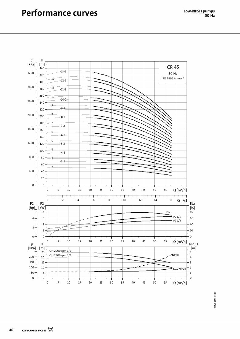
46
Performance curves Low
-NPSH pumps50 HzTMx1
145
1 0
303
0 5 10 15 20 25 30 35 40 45 50 55 Q [m³/h]
0
20
40
60
80
100
120
140
160
180
200
220
240
260
280
300
320
340
H[m]
0 2 4 6 8 10 12 14 16 Q [l/s]
0
400
800
1200
1600
2000
2400
2800
3200
[kPa]p
CR 4550 Hz
ISO 9906 Annex A
-13-2
-12-2-12
-11-2-11
-10-10-2
-2
-3-3-2
-4-4-2
-5-5-2
-6-6-2
-7-7-2
-8-8-2
-9-9-2
0 5 10 15 20 25 30 35 40 45 50 55 Q [m³/h]
0
1
2
3
4
P2[kW]
0
20
40
60
80
[%]Eta
0
2
4
[hp]P2
P2 1/1P2 2/3
Eta
0 5 10 15 20 25 30 35 40 45 50 55 Q [m³/h]
0
5
10
15
20
25[m]H
0
1
2
3
4
5
NPSH[m]
0
50
100
150
200
[kPa]p
Low NPSH
QH 2900 rpm 1/1
QH 2900 rpm 2/3 NPSH

Technical data Low-
NPSH pumps50 HzDimensional sketches Dimensions and weights
Electrical data 3 x 380-415 V, 50 Hz
TM0
1 17
51 5
197
8 x ø18
G 1/2
ø80266331
ø120
ø160
ø200
D2D1
190248365
B1
B2
G 1/2
G 1/2
4 x ø14
140
D3
45
PN16-25-40/DN80
Pump typeDimensions [mm] Net weight
[kg]B1 B2 B1 + B2 D1 D2 D3
CR 45-2 638 391 1029 220 134 298 118
CR 45-3-2 828 464 1292 260 172 350 159
CR 45-3 828 464 1292 260 172 350 159
CR 45-4-2 908 478 1386 306 197 350 196
CR 45-4 908 478 1386 306 197 350 196
CR 45-5-2 988 478 1466 306 197 350 210
CR 45-5 988 478 1466 306 197 350 210
CR 45-6-2 1068 600 1668 364 269 350 267
CR 45-6 1068 600 1668 364 269 350 267
CR 45-7-2 1148 667 1815 404 306 400 350
CR 45-7 1148 667 1815 404 306 400 350
CR 45-8-2 1228 667 1895 404 306 400 354
CR 45-8 1228 667 1895 404 306 400 354
CR 45-9-2 1308 667 1975 404 306 400 358
CR 45-9 1308 667 1975 404 306 400 358
CR 45-10-2 1388 667 2055 404 306 400 382
CR 45-10 1388 667 2055 404 306 400 382
CR 45-11-2 1468 715 2183 459 342 450 447
CR 45-11 1468 715 2183 459 342 450 447
CR 45-12-2 1556 715 2271 459 342 450 452
CR 45-12 1556 715 2271 459 342 450 452
CR 45-13-2 1636 715 2351 459 342 450 457
Pump typeMotor
P2 [kW]Full load current
I1/1 [A]Power factor
Cos ϕ 1/1Motor efficiency
η [%]
CR 45-2 7.5 15.2 0.87-0.81 88.0-88.0 9.1-9.9
CR 45-3-2 11.0 21.5 0.91-0.87 90.0-90.0 7.3-8.0
CR 45-3 11.0 21.5 0.91-0.87 90.0-90.0 7.3-8.0
CR 45-4-2 15.0 28.7 0.87 90.0 6.0
CR 45-4 15.0 28.7 0.87 90.0 6.0
CR 45-5-2 18.5 35.9-34.1 0.86 91.0 7.2
CR 45-5 18.5 35.9-34.1 0.86 91.0 7.2
CR 45-6-2 22.0 42.0-40.0 0.86 91.4 7.3
CR 45-6 22.0 42.0-40.0 0.86 91.4 7.3
CR 45-7-2 30.0 56.0-52.0 0.88 91.7 7.5
CR 45-7 30.0 56.0-52.0 0.88 91.7 7.5
CR 45-8-2 30.0 56.0-52.0 0.88 91.7 7.5
CR 45-8 30.0 56.0-52.0 0.88 91.7 7.5
CR 45-9-2 30.0 56.0-52.0 0.88 91.7 7.5
CR 45-9 37.0 68.0-63.0 0.89 92.4 7.8
CR 45-10-2 37.0 68.0-63.0 0.89 92.4 7.8
CR 45-10 37.0 68.0-63.0 0.89 92.4 7.8
CR 45-11-2 45.0 83.0-78.0 0.87 93.4 7.8
CR 45-11 45.0 83.0-78.0 0.87 93.4 7.8
CR 45-12-2 45.0 83.0-78.0 0.87 93.4 7.8
CR 45-12 45.0 83.0-78.0 0.87 93.4 7.8
CR 45-13-2 45.0 83.0-78.0 0.87 93.4 7.8
IstartI1/1
---------------
47

48
Performance curves Low
-NPSH pumps50 HzTM0
2 0
753
030
3
0 10 20 30 40 50 60 70 80Q [m³/h]
0
20
40
60
80
100
120
140
160
180
200
H[m]
0 5 10 15 20 Q [l/s]
0
400
800
1200
1600
2000
[kPa]p
CR 6450 Hz
ISO 9906 Annex A
-2
-2-1
-3
-3-1
-3-2
-4
-4-1
-4-2
-5
-5-1
-5-2
-6
-6-1
-6-2
-7-1
-7-2
0 10 20 30 40 50 60 70 80Q [m³/h]
0
2
4
6
8
P2[kW]
0
20
40
60
80
[%]Eta
0
2
4
6
8
10
[hp]P2
P2 1/1
P2 2/3
Eta
0 10 20 30 40 50 60 70 80Q [m³/h]
0
8
16
24
32
[m]H
0
2
4
6
8
NPSH[m]
0
100
200
300
[kPa]p
Low NPSH
QH 2900 rpm 1/1
QH 2900 rpm 2/3NPSH

Technical data Low-
NPSH pumps50 HzDimensional sketches Dimensions and weights
Electrical data 3 x 380-415 V, 50 Hz
TM0
1 17
53 5
197
ø100266331
ø150
ø180
ø220
D2D1
190248365
B1
B2
G 1/2 8 x ø18
G 1/2
G 1/2
4 x ø14
140
D3
45
PN16/DN100
PN25/DN100
45
4 x ø14
G 1/2
8 x ø22
ø235
ø190
ø150
331266ø100
Pump typeDimensions [mm] Net
weight[kg]B1 B2 B1 + B2 D1 D2 D3
CR 64-2-1 754 464 1218 260 172 350 158
CR 64-2 754 464 1218 260 172 350 158
CR 64-3-2 836 478 1314 306 197 350 196
CR 64-3-1 836 478 1314 306 197 350 196
CR 64-3 836 478 1314 306 197 350 205
CR 64-4-2 919 478 1397 306 197 350 209
CR 64-4-1 919 600 1519 364 269 350 262
CR 64-4 919 600 1519 364 269 350 262
CR 64-5-2 1001 667 1668 404 306 400 345
CR 64-5-1 1001 667 1668 404 306 400 345
CR 64-5 1001 667 1668 404 306 400 345
CR 64-6-2 1084 667 1751 404 306 400 350
CR 64-6-1 1084 667 1751 404 306 400 370
CR 64-6 1084 667 1751 404 306 400 370
CR 64-7-2 1166 667 1833 404 306 400 374
CR 64-7-1 1166 667 1833 404 306 400 374
Pump typeMotor
P2 [kW]Full load current
I1/1 [A]Power factor
Cos ϕ 1/1Motor efficiency
η [%]
CR 64-2-1 11.0 21.5 0.91-0.87 85.0 7.3-8.0
CR 64-2 11.0 21.5 0.91-0.87 85.0 7.3-8.0
CR 64-3-2 15.0 28.7 0.87 86.0 6.0
CR 64-3-1 15.0 28.7 0.87 86.0 6.0
CR 64-3 18.5 35.9-34.1 0.86 87.0 7.2
CR 64-4-2 18.5 35.9-34.1 0.86 87.0 7.2
CR 64-4-1 22.0 42.0-40.0 0.86 89.2 7.3
CR 64-4 22.0 42.0-40.0 0.86 89.2 7.3
CR 64-5-2 30.0 56.0-52.0 0.88 91.7 7.5
CR 64-5-1 30.0 56.0-52.0 0.88 91.7 7.5
CR 64-5 30.0 56.0-52.0 0.88 91.7 7.5
CR 64-6-2 30.0 56.0-52.0 0.88 91.7 7.5
CR 64-6-1 37.0 68.0-63.0 0.89 92.4 7.8
CR 64-6 37.0 68.0-63.0 0.89 92.4 7.8
CR 64-7-2 37.0 68.0-63.0 0.89 92.4 7.8
CR 64-7-1 37.0 68.0-63.0 0.89 92.4 7.8
IstartI1/1
---------------
49

50
Performance curves Low
-NPSH pumps60 HzTM0
2 25
74 4
5016
0 H
z, c
urv
es a
nd
dat
a
0.0 0.4 0.8 1.2 1.6 2.0 2.4 2.8 3.2 3.6 4.0 4.4 4.8 5.2 Q [m³/h]
0
20
40
60
80
100
120
140
160
180
200
220
240
H[m]
0.0 0.2 0.4 0.6 0.8 1.0 1.2 1.4 Q [l/s]
0
400
800
1200
1600
2000
[kPa]p
CR 360 Hz
ISO 9906 Annex A
-10
-11
-12
-13
-15
-17
-19
-21
-23
-25
-3
-4
-5
-6
-7-8
-9
0.0 0.4 0.8 1.2 1.6 2.0 2.4 2.8 3.2 3.6 4.0 4.4 4.8 5.2 Q [m³/h]
0.00
0.04
0.08
0.12
P2[kW]
0
20
40
60
Eta[%]
0.00
0.04
0.08
0.12
0.16
[hp]P2
P2
Eta
0.0 0.4 0.8 1.2 1.6 2.0 2.4 2.8 3.2 3.6 4.0 4.4 4.8 5.2 Q [m³/h]
0
3
6
9
H[m]
0
2
4
6
NPSH[m]
0
20
40
60
80
[kPa]p
Low NPSH
QH 3500 rpm
NPSH

Technical data Low-
NPSH pumps60 HzDimensional sketches Dimensions and weights
Electrical data 3 x 220-255/380-440 V, 60 Hz
Electrical data 3 x 220-277/380-480 V, 60 Hz
TM0
2 0
193
250
1
75
75
20
180
B1
B2
141100
250
ø10
0ø
89
180220
220
100
160
20
4 x ø13.5
19 x 24.5G 1/2
22G 1/2
50
4 x ø13.5
D2
D1
M10 x 40Rp 1
145
G 1/2 G 1/2
FGJ (DIN-ANSI-JIS)PN 25 / DN 25/32
A (Oval)
ø35
ø14
0
DIN
Oval
Pumptype
Dimensions [mm]Net weight
[kg]
Oval flange DIN flangeB2 D1 D2
Ova
l
DIN
B1 B1 + B2 B1 B1 + B2
CR 3-3 256 447 281 472 191 141 109 18.9 23.0
CR 3-4 274 465 299 490 191 141 109 19.2 23.3
CR 3-5 296 527 321 552 231 141 109 21.1 25.2
CR 3-6 314 545 339 570 231 141 109 22.8 26.9
CR 3-7 332 563 357 588 231 141 109 23.4 27.5
CR 3-8 350 581 375 606 231 141 109 24.2 28.3
CR 3-9 384 665 409 690 281 178 110 30.5 34.6
CR 3-10 402 683 427 708 281 178 110 31.0 35.1
CR 3-11 420 701 445 726 281 178 110 31.5 35.6
CR 3-12 438 719 463 744 281 178 110 34.0 38.1
CR 3-13 456 737 481 762 281 178 110 34.2 38.3
CR 3-15 492 773 517 798 281 178 110 34.8 38.9
CR 3-17 528 809 553 834 281 178 110 35.3 39.4
CR 3-19 - - 593 928 335 178 110 - 45.6
CR 3-21 - - 629 964 335 178 110 - 46.4
CR 3-23 - - 665 1000 335 178 110 - 47.2
CR 3-25 - - 701 1073 372 220 134 - 57.1
Pump typeMotor
P2 [kW]Full load current
I1/1 [A]Power factor
Cos ϕ 1/1Motor efficiency
η [%]
CR 3-3 0.55 2.40-2.18/1.38-1.26 0.88-0.82 80.5-82.0 4.80-6.00
CR 3-4 0.55 2.40-2.18/1.38-1.26 0.88-0.82 80.5-82.0 4.80-6.00
CR 3-5 0.75 3.15-2.85/1.82-1.64 0.89-0.84 82.0-84.0 5.10-6.50
CR 3-6 1.1 4.50-4.00/2.60-2.32 0.89-0.84 82.0-85.0 5.10-6.50
CR 3-7 1.1 4.50-4.00/2.60-2.32 0.89-0.84 82.0-85.0 5.10-6.50
CR 3-8 1.1 4.50-4.00/2.60-2.32 0.89-0.84 82.0-85.0 5.10-6.50
Pump typeMotor
P2 [kW]Full load current
I1/1 [A]Power factor
Cos ϕ 1/1Motor efficiency
η [%]
CR 3-9 1.5 5.70-5.00/3.30-2.90 0.89-0.78 80.5-82.0 5.90-8.40
CR 3-10 1.5 5.70-5.00/3.30-2.90 0.89-0.78 80.5-82.0 5.90-8.40
CR 3-11 1.5 5.70-5.00/3.30-2.90 0.89-0.78 80.5-82.0 5.90-8.40
CR 3-12 2.2 8.05-6.95/4.65-4.00 0.90-0.81 83.0-84.5 6.50-9.50
CR 3-13 2.2 8.05-6.95/4.65-4.00 0.90-0.81 83.0-84.5 6.50-9.50
CR 3-15 2.2 8.05-6.95/4.65-4.00 0.90-0.81 83.0-84.5 6.50-9.50
CR 3-17 2.2 8.05-6.95/4.65-4.00 0.90-0.81 83.0-84.5 6.50-9.50
CR 3-19 3.0 10.6-9.00/6.10-5.20 0.90-0.83 85.0-86.0 7.40-11.0
CR 3-21 3.0 10.6-9.00/6.10-5.20 0.90-0.83 85.0-86.0 7.40-11.0
CR 3-23 3.0 10.6-9.00/6.10-5.20 0.90-0.83 85.0-86.0 7.40-11.0
CR 3-25 4.0 13.6-11.4/7.85-6.60 0.92-0.85 86.0-87.0 8.00-12.0
IstartI1/1
---------------
IstartI1/1
---------------
51

52
Performance curves Low
-NPSH pumps60 HzTM0
2 25
75 4
501
0 1 2 3 4 5 6 7 8 9 10 Q [m³/h]
0
20
40
60
80
100
120
140
160
180
200
220
240
H[m]
0.0 0.5 1.0 1.5 2.0 2.5 3.0 Q [l/s]
0
400
800
1200
1600
2000
p[kPa] CR 5
60 HzISO 9906 Annex A
-10
-11
-12
-13
-14
-15
-16
-18
-20
-22
-24
-4
-5
-6
-7
-8
-9
0 1 2 3 4 5 6 7 8 9 10 Q [m³/h]
0.00
0.08
0.16
0.24
P2[kW]
0
20
40
60
Eta[%]
0.0
0.1
0.2
0.3
[hp]P2
P2Eta
0 1 2 3 4 5 6 7 8 9 10 Q [m³/h]
0
3
6
9
H[m]
0
2
4
6
NPSH[m]
0
20
40
60
80
[kPa]p
Low NPSH
QH 3500 rpm
NPSH

Technical data Low-
NPSH pumps60 HzDimensional sketches Dimensions and weights
Electrical data 3 x 220-255/380-440 V, 60 Hz
Electrical data 3 x 220-277/380-480 V, 60 Hz
TM0
2 0
449
350
3
DIN
Oval
ø35
ø14
0
75
20
180
ø10
0ø
89
180220
220
100
160
20
4 x ø13.5
19 x 24.5
22G 1/2
50
4 x ø13.5
M10 x 40Rp 1 1/4
145
D3
75B
1B
2
141100
250
G 1/2
D2D1
G 1/2 G 1/2
FGJ (DIN-ANSI-JIS)PN 25 / DN 25/32
A (Oval)
Pumptype
Dimensions [mm]Net weight
[kg]
Oval flange DIN flangeB2 D1 D2 D3
Ova
l
DIN
B1 B1+B2 B1 B1+B2
CR 5-4 314 545 339 570 231 141 109 - 22.8 26.9
CR 5-5 357 638 382 663 281 178 110 - 29.9 34.0
CR 5-6 384 665 409 690 281 178 110 - 32.5 36.6
CR 5-7 411 692 436 717 281 178 110 - 33.2 37.3
CR 5-8 438 719 463 744 281 178 110 - 34.0 38.1
CR 5-9 465 746 490 771 281 178 110 - 34.4 38.5
CR 5-10 496 831 521 856 335 178 110 - 40.3 44.4
CR 5-11 523 858 548 883 335 178 110 - 40.6 44.7
CR 5-12 550 885 575 910 335 178 110 - 41.0 45.1
CR 5-13 577 949 602 974 372 220 134 - 50.3 54.4
CR 5-14 604 976 629 1001 372 220 134 - 51.0 55.1
CR 5-15 631 1003 656 1028 372 220 134 - 51.6 55.7
CR 5-16 658 1030 683 1055 372 220 134 - 52.2 56.3
CR 5-18 - - 767 1158 391 220 134 300 - 70.5
CR 5-20 - - 821 1212 391 220 134 300 - 71.8
CR 5-22 - - 875 1266 391 220 134 300 - 72.8
CR 5-24 - - 929 1320 391 220 134 300 - 78.1
Pump typeMotor
P2 [kW]Full load current
I1/1 [A]Power factor
Cos ϕ 1/1Motor efficiency
η [%]
CR 5-4 1.1 4.50-4.00/2.60-2.32 0.89-0.84 82.0-85.0 5.10-6.50
Pump typeMotor
P2 [kW]Full load current
I1/1 [A]Power factor
Cos ϕ 1/1Motor efficiency
η [%]
CR 5-5 1.5 5.70-5.00/3.30-2.90 0.89-0.78 80.5-82.0 5.90-8.40
CR 5-6 2.2 8.05-6.95/4.65-4.00 0.90-0.81 83.0-84.5 6.50-9.50
CR 5-7 2.2 8.05-6.95/4.65-4.00 0.90-0.81 83.0-84.5 6.50-9.50
CR 5-8 2.2 8.05-6.95/4.65-4.00 0.90-0.81 83.0-84.5 6.50-9.50
CR 5-9 2.2 8.05-6.95/4.65-4.00 0.90-0.81 83.0-84.5 6.50-9.50
CR 5-10 3.0 10.6-9.00/6.10-5.20 0.90-0.83 85.0-86.0 7.40-11.0
CR 5-11 3.0 10.6-9.00/6.10-5.20 0.90-0.83 85.0-86.0 7.40-11.0
CR 5-12 3.0 10.6-9.00/6.10-5.20 0.90-0.83 85.0-86.0 7.40-11.0
CR 5-13 4.0 13.6-11.4/7.85-6.60 0.92-0.85 86.0-87.0 8.00-12.0
CR 5-14 4.0 13.6-11.4/7.85-6.60 0.92-0.85 86.0-87.0 8.00-12.0
CR 5-15 4.0 13.6-11.4/7.85-6.60 0.92-0.85 86.0-87.0 8.00-12.0
CR 5-16 4.0 13.6-11.4/7.85-6.60 0.92-0.85 86.0-87.0 8.00-12.0
CR 5-18 5.5 18.8-15.6/10.8-9.00 0.92-0.85 86.5-88.5 8.20-12.4
CR 5-20 5.5 18.8-15.6/10.8-9.00 0.92-0.85 86.5-88.5 8.20-12.4
CR 5-22 5.5 18.8-15.6/10.8-9.00 0.92-0.85 86.5-88.5 8.20-12.4
CR 5-24 7.5 25.5-22.6/14.6-13.0 0.92-0.80 87.5-89.0 9.50-11.6
IstartI1/1
---------------
IstartI1/1
---------------
53

54
Performance curves Low
-NPSH pumps60 HzTM0
2 73
94
510
3
0 1 2 3 4 5 6 7 8 9 10 11 12 13 14 15 16 Q [m³/h]
0
20
40
60
80
100
120
140
160
180
200
220
240
260
280
H[m]
0.0 0.5 1.0 1.5 2.0 2.5 3.0 3.5 4.0 4.5 Q [l/s]
0
400
800
1200
1600
2000
2400
p[kPa] CR, CRI, CRN 10
60 HzISO 9906 Annex A
-17
-16
-14
-12
-10
-9
-8
-7
-6
-5
-4
-3
0 1 2 3 4 5 6 7 8 9 10 11 12 13 14 15 16 Q [m³/h]
0.0
0.2
0.4
0.6
0.8
P2[kW]
0
20
40
60
80
Et[%
P2Eta
0 1 2 3 4 5 6 7 8 9 10 11 12 13 14 15 16 Q [m³/h]
0
4
8
12
16
H[m]
0
2
4
6
8
NP[m
3500 rpm
LOW NPSH
NPSH

Technical data Low-
NPSH pumps60 HzDimensional sketches Dimensions and weights
Electrical data 3 x 220-277/380-480 V, 60 Hz
TM0
2 6
574
100
3
B2
D2D1
4 x ø13.5130178
80
G 1/2
280
B1
G 1/2G 1/2
256
18 x 20.2
ø39
20
FJ (DIN-JIS)
ø11
4ø
150
178200
A (oval)
100
Rp 1 1/2"
M12 x 45
4 x ø13.5
27
215ø110
215256
130
80
20
G 1/2
PN 16-25 / DN 40
D3
Oval
Pump type
Dimensions [mm]Net weight
[kg]
Oval flange
DIN flange
Oval flange
DIN flange
B1 B1+B2 B1 B1+B2 D1 D2 D3 Oval DIN
CR 10-3 428 709 428 709 178 110 - 46.5 49.5
CR 10-4 428 763 428 763 178 110 - 49.0 52.0
CR 10-5 458 830 458 830 220 134 - 61.0 64.0
CR 10-6 488 860 488 860 220 134 - 61.0 64.0
CR 10-7 550 941 550 941 220 134 300 83.0 86.0
CR 10-8 580 971 580 971 220 134 300 84.0 87.0
CR 10-9 610 1001 610 1001 220 134 300 85.0 88.0
CR 10-10 640 1031 640 1031 220 134 300 88.0 91.0
CR 10-12 - - 700 1091 220 134 300 - 94.0
CR 10-14 - - 837 1301 260 172 352 - 127.0
CR 10-16 - - 897 1361 260 172 352 - 129.0
CR 10-17 - - 957 1421 260 172 352 - 131.0
Pump typeMotor
P2 [kW]Full load current
I1/1 [A]Power factor
Cos ϕ 1/1Motor efficiency
η [%]
CR 10-3 2.2 8.05-6.95/4.65-4.00 0.90-0.81 83.0-84.5 6.50-9.50
CR 10-4 3.0 10.6-9.00/6.10-5.20 0.90-0.83 85.0-86.0 7.40-11.0
CR 10-5 4.0 13.6-11.4/7.85-6.60 0.92-0.85 86.0-87.0 8.00-12.0
CR 10-6 4.0 13.6-11.4/7.85-6.60 0.92-0.85 86.0-87.0 8.00-12.0
CR 10-7 5.5 18.8-15.6/10.8-9.00 0.92-0.85 86.5-88.5 8.20-12.4
CR 10-8 5.5 18.8-15.6/10.8-9.00 0.92-0.85 86.5-88.5 8.20-12.4
CR 10-9 5.5 18.8-15.6/10.8-9.00 0.92-0.85 86.5-88.5 8.20-12.4
CR 10-10 7.5 25.5-22.6/14.6-13.0 0.92-0.80 87.5-89.0 9.50-11.6
CR 10-12 7.5 25.5-22.6/14.6-13.0 0.92-0.80 87.5-89.0 9.50-11.6
CR 10-14 11.0 38.0-32.5/22.0-18.8 0.92-0.86 89.0-91.0 6.80-8.60
CR 10-16 11.0 38.0-32.5/22.0-18.8 0.92-0.86 89.0-91.0 6.80-8.60
CR 10-17 11.0 38.0-32.5/22.0-18.8 0.92-0.86 89.0-91.0 6.80-8.60
IstartI1/1
---------------
55

56
Performance curves Low
-NPSH pumps60 HzTM0
2 2
739
5 34
03
0 2 4 6 8 10 12 14 16 18 20 22 24 26 28 Q [m³/h]
0
20
40
60
80
100
120
140
160
180
200
220
240
260
H[m]
0 1 2 3 4 5 6 7 8 Q [l/s]
0
400
800
1200
1600
2000
2400
p[kPa] CR, CRI, CRN 15
60 HzISO 9906 Annex A
-12
-10
-9
-8
-7
-6
-5
-4
-3
-2
0 2 4 6 8 10 12 14 16 18 20 22 24 26 28 Q [m³/h]
0.0
0.4
0.8
1.2
1.6
P2[kW]
0
20
40
60
80
Eta[%]
P2
Eta
0 2 4 6 8 10 12 14 16 18 20 22 24 26 28 Q [m³/h]
0
5
10
15
20
H[m]
0
2
4
6
8
NPSH[m]
3500 rpm
LOW NPSH
NPSH

Technical data Low-
NPSH pumps60 HzDimensional sketches Dimensions and weights
Electrical data 3 x 220-277/380-480 V, 60 Hz
TM0
2 6
5 76
10
03
B2
D2D1
G 1/2G 1/2 D3
4 x ø13.5130176
90
G 1/2
300215256
ø65
20
PN 16-25 / DN 50ø
125
ø16
5
GJ (ANSI-JIS)
Rp 2"
M12 x 45
ø16
5
ø65
18 x 21.5
ø12
7
ø120
A (oval)
130
30
ø18.1
256215
20
4 x ø13.5
300176130
90
G 1/2
130178200
90
215256
4 x ø13.520
G 1/2
B1
F (DIN)
Pump type
Dimensions [mm]Net weight
[kg]
Oval flange
DIN flange
Oval flange
DIN flange
B1 B1+B2 B1 B1+B2 D1 D2 D3 Oval DIN
CR 15-2 420 811 420 811 220 134 300 73.1 74.1
CR 15-3 465 856 465 856 220 134 300 75.0 76.0
CR 15-4 542 933 542 933 220 134 300 89.9 90.9
CR 15-5 587 1051 587 1051 260 172 352 115.0 116.0
CR 15-6 - - 709 1173 260 172 352 - 123.0
CR 15-7 - - 754 1232 306 197 352 - 139.0
CR 15-8 - - 799 1277 306 197 352 - 140.0
CR 15-9 - - 844 1322 306 197 352 - 143.0
CR 15-10 - - 889 1367 306 197 352 - 174.0
CR 15-12 - - 979 1457 306 197 352 178.0
Pump typeMotor
P2 [kW]Full load current
I1/1 [A]Power factor
Cos ϕ 1/1Motor efficiency
η [%]
CR 15-2 5.5 18.8-15.6/10.8-9.00 0.92-0.85 86.5-88.5 8.20-12.4
CR 15-3 5.5 18.8-15.6/10.8-9.00 0.92-0.85 86.5-88.5 8.20-12.4
CR 15-4 7.5 25.5-22.6/14.6-13.0 0.92-0.80 87.5-89.0 9.50-11.6
CR 15-5 11.0 38.0-32.5/22.0-18.8 0.92-0.86 89.0-91.0 6.80-8.60
CR 15-6 11.0 38.0-32.5/22.0-18.8 0.92-0.86 89.0-91.0 6.80-8.60
CR 15-7 15.0 48.8-41.0/28.1-23.7 0.91-0.86 90.0-92.0 5.40-9.15
CR 15-8 15.0 48.8-41.0/28.1-23.7 0.91-0.86 90.0-92.0 5.40-9.15
CR 15-9 15.0 48.8-41.0/28.1-23.7 0.91-0.86 90.0-92.0 5.40-9.15
CR 15-10 18.5 58.7-56.8/34.0-32.8 0.87 91.0-93.0 6.0-7.9
CR 15-12 18.5 58.7-56.8/34.0-32.8 0.87 91.0-93.0 6.0-7.9
IstartI1/1
---------------
57

58
Performance curves Low
-NPSH pumps60 HzTM0
2 2
739
6 3
403
0 4 8 12 16 20 24 28 32 Q [m³/h]
0
20
40
60
80
100
120
140
160
180
200
H[m]
0 2 4 6 8 10 Q [l/s]
0
400
800
1200
1600
2000
p[kPa] CR, CRI, CRN 20
60 HzISO 9906 Annex A
-8
-7
-6
-5
-4
-3
-2
0 4 8 12 16 20 24 28 32 Q [m³/h]
0.0
0.4
0.8
1.2
1.6
P2[kW]
0
20
40
60
80
Eta[%]
P2
Eta
0 4 8 12 16 20 24 28 32 Q [m³/h]
0
5
10
15
20
H[m]
0
2
4
6
8
NPSH[m]3500 rpm
LOW NPSH
NPSH
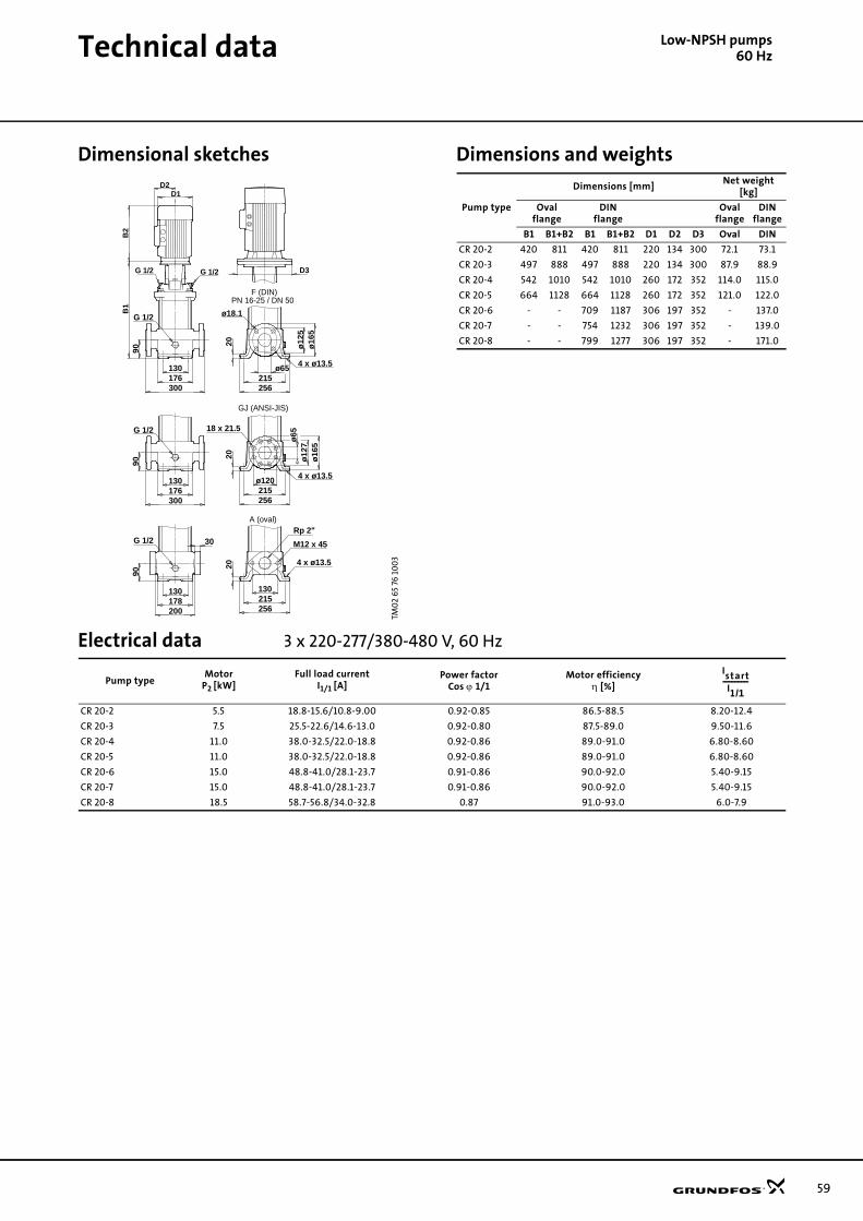
Technical data Low-
NPSH pumps60 HzDimensional sketches Dimensions and weights
Electrical data 3 x 220-277/380-480 V, 60 Hz
TM0
2 6
5 76
10
03
B2
D2D1
G 1/2G 1/2 D3
4 x ø13.5130176
90
G 1/2
300215256
ø65
20
PN 16-25 / DN 50ø
125
ø16
5
GJ (ANSI-JIS)
Rp 2"
M12 x 45
ø16
5
ø65
18 x 21.5
ø12
7
ø120
A (oval)
130
30
ø18.1
256215
20
4 x ø13.5
300176130
90
G 1/2
130178200
90
215256
4 x ø13.520
G 1/2
B1
F (DIN)
Pump type
Dimensions [mm]Net weight
[kg]
Oval flange
DIN flange
Oval flange
DIN flange
B1 B1+B2 B1 B1+B2 D1 D2 D3 Oval DIN
CR 20-2 420 811 420 811 220 134 300 72.1 73.1
CR 20-3 497 888 497 888 220 134 300 87.9 88.9
CR 20-4 542 1010 542 1010 260 172 352 114.0 115.0
CR 20-5 664 1128 664 1128 260 172 352 121.0 122.0
CR 20-6 - - 709 1187 306 197 352 - 137.0
CR 20-7 - - 754 1232 306 197 352 - 139.0
CR 20-8 - - 799 1277 306 197 352 - 171.0
Pump typeMotor
P2 [kW]Full load current
I1/1 [A]Power factor
Cos ϕ 1/1Motor efficiency
η [%]
CR 20-2 5.5 18.8-15.6/10.8-9.00 0.92-0.85 86.5-88.5 8.20-12.4
CR 20-3 7.5 25.5-22.6/14.6-13.0 0.92-0.80 87.5-89.0 9.50-11.6
CR 20-4 11.0 38.0-32.5/22.0-18.8 0.92-0.86 89.0-91.0 6.80-8.60
CR 20-5 11.0 38.0-32.5/22.0-18.8 0.92-0.86 89.0-91.0 6.80-8.60
CR 20-6 15.0 48.8-41.0/28.1-23.7 0.91-0.86 90.0-92.0 5.40-9.15
CR 20-7 15.0 48.8-41.0/28.1-23.7 0.91-0.86 90.0-92.0 5.40-9.15
CR 20-8 18.5 58.7-56.8/34.0-32.8 0.87 91.0-93.0 6.0-7.9
IstartI1/1
---------------
59

60
Performance curves Low
-NPSH pumps60 HzTM0
2 25
78 0
303
0 4 8 12 16 20 24 28 32 36 40 44 Q [m³/h]
0
20
40
60
80
100
120
140
160
180
200
220
240
260
280
H[m]
0 2 4 6 8 10 12 Q [l/s]
0
400
800
1200
1600
2000
2400
[kPa]p
CR 3260 Hz
ISO 9906 Annex A
-10-2
-2-2-1
-3
-3-2
-4
-4-2
-5
-5-2
-6
-6-2
-7-7-2
-8-8-2
-9-9-2
0 4 8 12 16 20 24 28 32 36 40 44 Q [m³/h]
0.0
0.8
1.6
2.4
3.2
P2[kW]
0
20
40
60
80[%]Eta
0
1
2
3
4
[hp]P2
P2 1/1
P2 2/3Eta
0 4 8 12 16 20 24 28 32 36 40 44 Q [m³/h]
0
8
16
24
32[m]H
0
2
4
6
8
NPSH[m]
0
80
160
240
[kPa]p
Low NPSHQH 3500 rpm 1/1QH 3500 rpm 2/3
NPSH

Technical data Low-
NPSH pumps60 HzDimensional sketches Dimensions and weights
Electrical data 3 x 220-277/380-480 V, 60 Hz
TM0
1 17
49 5
197ø74
240298
ø107
ø145
ø185
D2D1
170223320
B1
B2
G 1/2 8 x ø18
G 1/2
G 1/2
4 x ø14
105
D3
30
PN16-25-40/DN65
Pump typeDimensions [mm] Net
weight[kg]B1 B2 B1 + B2 D1 D2 D3
CR 32-2-1 575 391 966 220 134 298 103
CR 32-2 575 391 966 220 134 298 107
CR 32-3-2 755 464 1219 260 172 350 148
CR 32-3 755 464 1219 260 172 350 148
CR 32-4-2 825 464 1289 260 172 350 158
CR 32-4 825 478 1303 306 197 350 185
CR 32-5-2 895 478 1373 306 197 350 189
CR 32-5 895 478 1373 306 197 350 199
CR 32-6-2 965 478 1443 306 197 350 203
CR 32-6 965 478 1443 306 197 350 203
CR 32-7-2 1035 600 1635 364 269 350 260
CR 32-7 1035 600 1635 364 269 350 260
CR 32-8-2 1105 667 1772 404 306 400 342
CR 32-8 1105 667 1772 404 306 400 342
CR 32-9-2 1175 667 1842 404 306 400 346
CR 32-9 1175 667 1842 404 306 400 346
CR 32-10-2 1245 667 1912 404 306 400 350
Pump typeMotor
P2 [kW]Full load current
I1/1 [A]Power factor
Cos ϕ 1/1Motor efficiency
η [%]
CR 32-2-1 5.5 18.8-15.6/10.8-9.00 0.92-0.85 86.5-88.5 8.20-12.4
CR 32-2 7.5 25.5-22.6/14.6-13.0 0.92-0.80 87.5-89.0 9.50-11.6
CR 32-3-2 11.0 38.0-32.5/22.0-18.8 0.92-0.86 89.0-91.0 6.80-8.60
CR 32-3 11.0 38.0-32.5/22.0-18.8 0.92-0.86 89.0-91.0 6.80-8.60
CR 32-4-2 11.0 38.0-32.5/22.0-18.8 0.92-0.86 89.0-91.0 6.80-8.60
CR 32-4 15.0 48.8-41.0/28.1-23.7 0.91-0.86 90.0-92.0 5.40-9.15
CR 32-5-2 15.0 48.8-41.0/28.1-23.7 0.91-0.86 90.0-92.0 5.40-9.15
CR 32-5 18.5 58.7-56-8/34-0-32-8 0.87 91.0-93.0 6.0-7.9
CR 32-6-2 18.5 58.7-56-8/34-0-32-8 0.87 91.0-93.0 6.0-7.9
CR 32-6 18.5 58.7-56-8/34-0-32-8 0.87 91.0-93.0 6.0-7.9
CR 32-7-2 22.0 75.0-61.0/43.0-35.0 0.86 91.0-93.0 5.1-7.9
CR 32-7 22.0 75.0-61.0/43.0-35.0 0.86 91.0-93.0 5.1-7.9
CR 32-8-2 30.0 100-78.0/58.0-45.0 0.87 91.0-93.0 5.0-8.1
CR 32-8 30.0 100-78.0/58.0-45.0 0.87 91.0-93.0 5.0-8.1
CR 32-9-2 30.0 100-78.0/58.0-45.0 0.87 91.0-93.0 5.0-8.1
CR 32-9 30.0 100-78.0/58.0-45.0 0.87 91.0-93.0 5.0-8.1
CR 32-10-2 30.0 100-78.0/58.0-45.0 0.87 91.0-93.0 5.0-8.1
IstartI1/1
---------------
61

62
Performance curves Low
-NPSH pumps60 HzTM0
2 25
79 0
303
0 5 10 15 20 25 30 35 40 45 50 55 60 65 Q [m³/h]
0
20
40
60
80
100
120
140
160
180
200
220
240
260
H[m]
0 2 4 6 8 10 12 14 16 18 Q [l/s]
0
400
800
1200
1600
2000
2400
[kPa]p
CR 4560 Hz
ISO 9906 Annex A
-6-1
-7-2-7-1
-7
-2-2-1
-3-3-1
-3-2
-4-4-1
-4-2
-5-5-1
-5-2
-6
-6-2
0 5 10 15 20 25 30 35 40 45 50 55 60 65 Q [m³/h]
0
2
4
6
8
P2[kW]
0
20
40
60
80
[%]Eta
0
2
4
6
8
10
[hp]P2
P2 1/1P2 2/3
Eta
0 5 10 15 20 25 30 35 40 45 50 55 60 65 Q [m³/h]
0
10
20
30
40
[m]H
0
2
4
6
8
NPSH[m]
0
100
200
300
400[kPa]
p
Low NPSH
QH 3500 rpm 1/1
QH 3500 rpm 2/3NPSH

Technical data Low-
NPSH pumps60 HzDimensional sketches Dimensions and weights
Electrical data 3 x 220-277/380-480 V, 60 Hz
TM0
1 17
51 5
197
8 x ø18
G 1/2
ø80266331
ø120
ø160
ø200
D2D1
190248365
B1
B2
G 1/2
G 1/2
4 x ø14
140
D3
45
PN16-25-40/DN80
Pump typeDimensions [mm] Net
weight[kg]B1 B2 B1 + B2 D1 D2 D3
CR 45-2-1 748 464 1212 260 172 350 154
CR 45-2 748 478 1226 306 197 350 187
CR 45-3-2 828 478 1306 306 197 350 201
CR 45-3-1 828 478 1306 306 197 350 201
CR 45-3 828 478 1306 306 197 350 201
CR 45-4-2 908 600 1508 364 269 350 258
CR 45-4-1 908 667 1575 404 306 400 336
CR 45-4 908 667 1575 404 306 400 336
CR 45-5-2 988 667 1655 404 306 400 341
CR 45-5-1 988 667 1655 404 306 400 341
CR 45-5 988 667 1655 404 306 400 341
CR 45-6-2 1068 667 1735 404 306 400 365
CR 45-6-1 1068 667 1735 404 306 400 365
CR 45-6 1068 667 1735 404 306 400 365
CR 45-7-2 1148 715 1863 459 342 450 435
CR 45-7-1 1148 715 1863 459 342 450 435
CR 45-7 1148 715 1863 459 342 450 435
Pump typeMotor
P2 [kW]Full load current
I1/1 [A]Power factor
Cos ϕ 1/1Motor efficiency
η [%]
CR 45-2-1 11.0 38.0-32.5/22.0-18.8 0.92-0.86 89.0-91.0 6.80-8.60
CR 45-2 15.0 48.8-41.0/28.1-23.7 0.91-0.86 90.0-92.0 5.40-9.15
CR 45-3-2 18.5 58.7-56-8/34-0-32-8 0.87 91.0-93.0 6.0-7.9
CR 45-3-1 18.5 58.7-56-8/34-0-32-8 0.87 91.0-93.0 6.0-7.9
CR 45-3 18.5 58.7-56-8/34-0-32-8 0.87 91.0-93.0 6.0-7.9
CR 45-4-2 22.0 75.0-61.0/43.0-35.0 0.86 91.0-93.0 5.1-7.9
CR 45-4-1 30.0 100-78.0/58.0-45.0 0.87 91.0-93.0 5.0-8.1
CR 45-4 30.0 100-78.0/58.0-45.0 0.87 91.0-93.0 5.0-8.1
CR 45-5-2 30.0 100-78.0/58.0-45.0 0.87 91.0-93.0 5.0-8.1
CR 45-5-1 30.0 100-78.0/58.0-45.0 0.87 91.0-93.0 5.0-8.1
CR 45-5 30.0 100-78.0/58.0-45.0 0.87 91.0-93.0 5.0-8.1
CR 45-6-2 37.0 121-94.0/70.0-54.0 0.89 92.0-94.0 5.2-8.5
CR 45-6-1 37.0 121-94.0/70.0-54.0 0.89 92.0-94.0 5.2-8.5
CR 45-6 37.0 121-94.0/70.0-54.0 0.89 92.0-94.0 5.2-8.5
CR 45-7-2 45.0 145-118/84.0-66.0 0.88 93.0-95.0 5.6-8.5
CR 45-7-1 45.0 145-118/84.0-66.0 0.88 93.0-95.0 5.6-8.5
CR 45-7 45.0 145-118/84.0-66.0 0.88 93.0-95.0 5.6-8.5
IstartI1/1
---------------
63

64
Performance curves Low
-NPSH pumps60 HzTM0
2 25
80 0
303
0 10 20 30 40 50 60 70 80 90 Q [m³/h]
0
20
40
60
80
100
120
140
160
180
H[m]
0 5 10 15 20 25 Q [l/s]
0
400
800
1200
1600
[kPa]p
CR 6460 Hz
ISO 9906 Annex A
-5-2
-4
-2
-2-1
-3
-3-1
-3-2
-4-1
-4-2
0 10 20 30 40 50 60 70 80 90 Q [m³/h]
0
4
8
12
16
P2[kW]
0
20
40
60
80
[%]Eta
0
4
8
12
16
20
[hp]P2
P2 1/1
P2 2/3
Eta
0 10 20 30 40 50 60 70 80 90 Q [m³/h]
0
10
20
30
40
[m]H
0
2
4
6
8
NPSH[m]
0
100
200
300
400[kPa]
p
Low NPSH
QH 3500 rpm 1/1
QH 3500 rpm 2/3
NPSH

Technical data Low-
NPSH pumps60 HzDimensional sketches Dimensions and weights
Electrical data 3 x 220-277/380-480 V, 60 Hz
TM0
1 17
53 5
197ø100
266331
ø150
ø180
ø220
D2D1
190248365
B1
B2
G 1/2 8 x ø18
G 1/2
G 1/2
4 x ø14
140
D3
45
PN16/DN100
PN25/DN10045
4 x ø14
G 1/2
8 x ø22
ø235
ø190
ø150
331266ø100
Pump typeDimensions [mm] Net
weight[kg]B1 B2 B1 + B2 D1 D2 D3
CR 64-2-1 754 478 1232 306 197 350 199
CR 64-2 754 600 1354 364 269 350 252
CR 64-3-2 836 600 1503 404 306 400 252
CR 64-3-1 836 667 1503 404 306 400 330
CR 64-3 836 667 1503 404 306 400 335
CR 64-4-2 919 667 1586 404 306 400 360
CR 64-4-1 919 667 1586 404 306 400 360
CR 64-4 919 715 1634 459 342 450 425
CR 64-5-2 1001 715 1716 459 342 450 430
Pump typeMotor
P2 [kW]Full load current
I1/1 [A]Power factor
Cos ϕ 1/1Motor efficiency
η [%]
CR 64-2-1 18.5 58.7-56-8/34-0-32-8 0.87 91.0-93.0 6.0-7.9
CR 64-2 22.0 75.0-61.0/43.0-35.0 0.86 91.0-93.0 5.1-7.9
CR 64-3-2 22.0 75.0-61.0/43.0-35.0 0.86 91.0-93.0 5.1-7.9
CR 64-3-1 30.0 100-78.0/58.0-45.0 0.87 91.0-93.0 5.0-8.1
CR 64-3 30.0 100-78.0/58.0-45.0 0.87 91.0-93.0 5.0-8.1
CR 64-4-2 37.0 121-94.0/70.0-54.0 0.89 92.0-94.0 5.2-8.5
CR 64-4-1 37.0 121-94.0/70.0-54.0 0.89 92.0-94.0 5.2-8.5
CR 64-4 45.0 145-118/84.0-66.0 0.88 93.0-95.0 5.6-8.5
CR 64-5-2 45.0 145-118/84.0-66.0 0.88 93.0-95.0 5.6-8.5
IstartI1/1
---------------
65

66
4-pole versions Custom
-built pumpsCR pumps with 4-pole motors
General information
CR standard pumps fitted with 4-pole motors.
Reference applications
• Applications where a low sound pressure level isrequired
• Applications with poor inlet conditions.
Pump range
The following Grundfos pumps are available as 4-poleversions:
50 and 60 Hz
Technical description
Calculation of motor size:
Use the P2 curve on the following curve sheets to calcu-late the 4-pole motor size.
The minimum motor size available for each pump type isshown in the table.
Reference numbers
GR
5381
Pump type
CR 1s CR 1 CR 3 CR 5 CR 10 CR 15 CR 20 CR 32 CR 45 CR 64 CR 90
CR
CRI
CRN
Pump sizeMotor size
[kW]
CR 1 0.25
CR 3 0.25
CR 5 0.25
CR 10 0.25
CR 15 0.25
CR20 0.25
CR 32 1.1
CR 45 1.1
CR 64 1.1
CR 90 1.1
Pump type Reference number
CR, CRI, CRN 1, 3, 5, 10, 15 and 2099 97 24
CR, CRN 32, 45 and 64

Performance curves 4-pole ve
rsions, 50 HzTM0
2 25
43 4
5015
0 H
Z, c
urv
es
0.0 0.1 0.2 0.3 0.4 0.5 0.6 0.7 0.8 0.9 1.0 1.1 Q [m³/h]
0
5
10
15
20
25
30
35
40
45
50
55
H[m]
0.00 0.05 0.10 0.15 0.20 0.25 0.30 Q [l/s]
0
100
200
300
400
500
p[kPa] CR, CRI, CRN 1
50 HzISO 9906 Annex A
-10-11
-12-13
-15
-17
-19
-2
-21
-23
-25
-27
-3
-30
-33
-36
-4-5
-6-7
-8-9
0.0 0.1 0.2 0.3 0.4 0.5 0.6 0.7 0.8 0.9 1.0 1.1 Q [m³/h]
0.000
0.005
0.010
P2[kW]
0
20
40
Eta[%]
0.000
0.005
0.010
0.015[hp]P2
P2
Eta
0.0 0.1 0.2 0.3 0.4 0.5 0.6 0.7 0.8 0.9 1.0 1.1 Q [m³/h]
0
1
2
H[m]
0.0
0.5
1.0
NPSH[m]
0
10
20
[kPa]p
QH 1450 rpm
NPSH
67

68
Performance curves 4-pole v
ersions, 50 HzTM0
2 25
42 4
501
0.0 0.2 0.4 0.6 0.8 1.0 1.2 1.4 1.6 1.8 2.0 Q [m³/h]
0
5
10
15
20
25
30
35
40
45
50
55
60
H[m]
0.0 0.1 0.2 0.3 0.4 0.5 0.6 Q [l/s]
0
100
200
300
400
500
p[kPa] CR, CRI, CRN 3
50 HzISO 9906 Annex A
-10-11
-12-13
-15
-17
-19
-2
-21
-23
-25
-27
-29
-3
-31
-33
-36
-4-5
-6-7
-8-9
0.0 0.2 0.4 0.6 0.8 1.0 1.2 1.4 1.6 1.8 2.0 Q [m³/h]
0.000
0.005
0.010
0.015
P2[kW]
0
20
40
60
[%]Eta
0.000
0.005
0.010
0.015
0.020
[hp]P2
EtaP2
0.0 0.2 0.4 0.6 0.8 1.0 1.2 1.4 1.6 1.8 2.0 Q [m³/h]
0.0
0.5
1.0
1.5
H[m]
0.0
0.5
1.0
1.5
NPSH[m]
0
5
10
15
[kPa]p
NPSH
QH 1450 rpm

Performance curves 4-pole ve
rsions, 50 HzTM0
2 25
41 4
501
0.0 0.4 0.8 1.2 1.6 2.0 2.4 2.8 3.2 3.6 4.0 Q [m³/h]
0
5
10
15
20
25
30
35
40
45
50
55
60
65
H[m]
0.0 0.2 0.4 0.6 0.8 1.0 1.2 Q [l/s]
0
100
200
300
400
500
600
p[kPa] CR, CRI, CRN 5
50 HzISO 9906 Annex A
-10-11
-12-13
-14-15
-16
-18
-2
-20
-22
-24
-26
-29
-3
-32
-36
-4-5
-6-7
-8-9
0.0 0.4 0.8 1.2 1.6 2.0 2.4 2.8 3.2 3.6 4.0 Q [m³/h]
0.000
0.005
0.010
0.015
P2[kW]
0
20
40
60
Eta[%]
0.000
0.005
0.010
0.015
0.020
[hp]P2
EtaP2
0.0 0.4 0.8 1.2 1.6 2.0 2.4 2.8 3.2 3.6 4.0 Q [m³/h]
0.0
0.5
1.0
1.5
H[m]
0.0
0.5
1.0
1.5
NPSH[m]
0
5
10
15
[kPa]p
NPSH
QH 1450 rpm
69

70
Performance curves 4-pole v
ersions, 50 HzTM0
2 72
73 3
103
0.0 0.5 1.0 1.5 2.0 2.5 3.0 3.5 4.0 4.5 5.0 5.5 6.0 Q [m³/h]
0
5
10
15
20
25
30
35
40
45
50
55
60
H[m]
0.0 0.2 0.4 0.6 0.8 1.0 1.2 1.4 1.6 Q [l/s]
0
100
200
300
400
500
p[kPa] CR, CRI, CRN 10
50 HzISO 9906 Annex A
-1
-10
-12
-14
-16
-18
-2
-20
-22
-3
-4
-5
-6
-7
-8
-9
0.0 0.5 1.0 1.5 2.0 2.5 3.0 3.5 4.0 4.5 5.0 5.5 6.0 Q [m³/h]
0.00
0.02
0.04
0.06
P2[kW]
0
20
40
60
Eta[%]
0.00
0.02
0.04
0.06
0.08
[hp]P2
P2
Eta
0.0 0.5 1.0 1.5 2.0 2.5 3.0 3.5 4.0 4.5 5.0 5.5 6.0 Q [m³/h]
0.0
0.8
1.6
2.4
H[m]
0.0
0.5
1.0
1.5
NPSH[m]
0
10
20
[kPa]p
QH 1450 rpm
NPSH

Performance curves 4-pole ve
rsions, 50 HzTM0
2 72
74 3
103
0 1 2 3 4 5 6 7 8 9 10 11 Q [m³/h]
0
5
10
15
20
25
30
35
40
45
50
55
60
H[m]
0.0 0.5 1.0 1.5 2.0 2.5 3.0 Q [l/s]
0
100
200
300
400
500
p[kPa] CR, CRI, CRN 15
50 HzISO 9906 Annex A
-1
-10
-12
-14
-17
-2
-3
-4
-5
-6
-7
-8
-9
0 1 2 3 4 5 6 7 8 9 10 11 Q [m³/h]
0.00
0.04
0.08
0.12
P2[kW]
0
20
40
60
Eta[%]
0.00
0.04
0.08
0.12
0.16
[hp]P2
Eta
P2
0 1 2 3 4 5 6 7 8 9 10 11 Q [m³/h]
0
1
2
3
H[m]
0.0
0.5
1.0
1.5
NPSH[m]
0
10
20
30
[kPa]p
NPSH
QH 1450 rpm
71

72
Performance curves 4-pole v
ersions, 50 HzTM0
2 72
75 3
103
0 1 2 3 4 5 6 7 8 9 10 11 12 13 14 Q [m³/h]
0
5
10
15
20
25
30
35
40
45
50
55
60
65
H[m]
0.0 0.5 1.0 1.5 2.0 2.5 3.0 3.5 4.0 Q [l/s]
0
100
200
300
400
500
600
p[kPa] CR, CRI, CRN 20
50 HzISO 9906 Annex A
-1
-10
-12
-14
-17
-2
-3
-4
-5
-6
-7
-8
0 1 2 3 4 5 6 7 8 9 10 11 12 13 14 Q [m³/h]
0.00
0.05
0.10
0.15
P2[kW]
0
20
40
60
Eta[%]
0.00
0.05
0.10
0.15
0.20
[hp]P2
Eta
P2
0 1 2 3 4 5 6 7 8 9 10 11 12 13 14 Q [m³/h]
0
1
2
3
H[m]
0.0
0.5
1.0
1.5
NPSH[m]
0
10
20
30
[kPa]p
NPSH
QH 1450 rpm
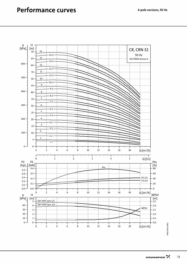
Performance curves 4-pole ve
rsions, 50 HzTM0
1 81
53 1
802
0 2 4 6 8 10 12 14 16 18 Q [m³/h]
0
5
10
15
20
25
30
35
40
45
50
55
60
65
70
H[m]
0 1 2 3 4 5 Q [l/s]
0
100
200
300
400
500
600
[kPa]p
CR, CRN 3250 Hz
ISO 9906 Annex A
10
10-2
11
11-2
12
12-2
14
13
13-2
14-2
2-2
3
3-2
4
4-2
5
5-2
6
6-2
7
7-2
8
8-2
9
9-2
1-1
1
2
0 2 4 6 8 10 12 14 16 18 Q [m³/h]
0.0
0.1
0.2
0.3
0.4
P2[kW]
0
20
40
60
80[%]Eta
0.0
0.1
0.2
0.3
0.4
0.5
[hp]P2
P2 1/1P2 2/3
Eta
0 2 4 6 8 10 12 14 16 18 Q [m³/h]
0
1
2
3
4
5[m]H
0.0
0.5
1.0
1.5
2.0
2.5
NPSH[m]
0
10
20
30
40
[kPa]p
QH 1450 rpm 1/1
QH 1450 rpm 2/3
NPSH
73

74
Performance curves 4-pole v
ersions, 50 HzTM0
1 81
54 1
802
0 2 4 6 8 10 12 14 16 18 20 22 24 26 28 Q [m³/h]
0
5
10
15
20
25
30
35
40
45
50
55
60
65
70
75
80
85
H[m]
0 1 2 3 4 5 6 7 8 Q [l/s]
0
100
200
300
400
500
600
700
800
[kPa]p
CR, CRN 4550 Hz
ISO 9906 Annex A
13-2
12 12-2
11 11-2
10
10-2
9 9-2
8
8-2
7
7-2
6
6 -2
5
5-2
4
4-2 3
3-2 2
2-2 1
1-1
0 2 4 6 8 10 12 14 16 18 20 22 24 26 28 Q [m³/h]
0.0
0.1
0.2
0.3
0.4
P2[kW]
0
20
40
60
80
[%]Eta
0.0
0.2
0.4
[hp]P2
P2 1/1 Eta
P2 2/3
0 2 4 6 8 10 12 14 16 18 20 22 24 26 28 Q [m³/h]
0
2
4
6
[m]H
0.0
0.5
1.0
1.5
NPSH[m]
0
20
40
60
[kPa]p
QH 1450 rpm 1/1
NPSH
QH 1450 rpm 2/3

Performance curves 4-pole ve
rsions, 50 HzTM0
1 81
55 1
802
0 5 10 15 20 25 30 35 40Q [m³/h]
0
5
10
15
20
25
30
35
40
45
50
55
H[m]
0 2 4 6 8 10 Q [l/s]
0
100
200
300
400
500
[kPa]p
CR, CRN 6450 Hz
ISO 9906 Annex A
1-1
1
2-2
2-1
2
3-2
3-1
3 4-2
4-1
4
5-2
5-1
5 6-2
6-1
6 7-2
7-1
7
8-2
8-1
0 5 10 15 20 25 30 35 40Q [m³/h]
0.0
0.2
0.4
0.6
0.8
P2[kW]
0
20
40
60
80
[%]Eta
0.0
0.2
0.4
0.6
0.8
1.0
[hp]P2
P2 1/1
P2 2/3
Eta
0 5 10 15 20 25 30 35 40Q [m³/h]
0
2
4
6
[m]H
0.0
0.4
0.8
1.2
NPSH[m]
0
20
40
60
[kPa]p
QH 1450 rpm 1/1
QH 1450 rpm 2/3
NPSH
75

76
Performance curves 4-pole v
ersions, 50 HzTM0
1 81
56 1
802
0 5 10 15 20 25 30 35 40 45 50 55 Q [m³/h]
0
5
10
15
20
25
30
35
40
45
50
H[m]
0 2 4 6 8 10 12 14 16 Q [l/s]
0
100
200
300
400
500
[kPa]p
CR, CRN 9050 Hz
ISO 9906 Annex A
6
6-2
5-2
5
4
4-2
3
3-2
2
2-2
1
1-1
0 5 10 15 20 25 30 35 40 45 50 55 Q [m³/h]
0.00
0.25
0.50
0.75
1.00
P2[kW]
0
20
40
60
80
[%]Eta
0.0
0.5
1.0
[hp]P2
P2 1/1
P2 2/3
Eta
0 5 10 15 20 25 30 35 40 45 50 55 Q [m³/h]
0
2
4
6
8
[m]H
0.0
0.4
0.8
1.2
1.6
NPSH[m]
0
20
40
60
80[kPa]
p
QH 1450 rpm 1/1
QH 1450 rpm 2/3
NPSH

Performance curves 4-pole ve
rsions, 60 HzTM0
2 25
40 4
5016
0 H
Z, c
urv
es
0.0 0.1 0.2 0.3 0.4 0.5 0.6 0.7 0.8 0.9 1.0 1.1 1.2 1.3 1.4 Q [m³/h]
0
5
10
15
20
25
30
35
40
45
50
55
60
H[m]
0.00 0.05 0.10 0.15 0.20 0.25 0.30 0.35 0.40 Q [l/s]
0
100
200
300
400
500
p[kPa] CR, CRI, CRN 1
60 HzISO 9906 Annex A
-10
-11-12
-13
-15
-17
-19
-2
-21
-23
-25
-27
-3
-4
-5-6
-7
-8-9
0.0 0.1 0.2 0.3 0.4 0.5 0.6 0.7 0.8 0.9 1.0 1.1 1.2 1.3 1.4 Q [m³/h]
0.000
0.005
0.010
0.015
P2[kW]
0
20
40
60
Eta[%]
0.000
0.005
0.010
0.015
0.020
[hp]P2
EtaP2
0.0 0.1 0.2 0.3 0.4 0.5 0.6 0.7 0.8 0.9 1.0 1.1 1.2 1.3 1.4 Q [m³/h]
0
1
2
3
H[m]
0.0
0.5
1.0
1.5
NPSH[m]
0
10
20
30
[kPa]p
NPSH
QH 1750 rpm
77

78
Performance curves 4-pole v
ersions, 60 HzTM0
2 25
39 4
501
0.0 0.2 0.4 0.6 0.8 1.0 1.2 1.4 1.6 1.8 2.0 2.2 2.4 2.6 Q [m³/h]
0
5
10
15
20
25
30
35
40
45
50
55
60
H[m]
0.0 0.1 0.2 0.3 0.4 0.5 0.6 0.7 Q [l/s]
0
100
200
300
400
500
p[kPa] CR, CRI, CRN 3
60 HzISO 9906 Annex A
-2
-10
-11
-12
-13
-15
-17
-19
-21
-23
-25
-3
-4
-5
-6
-7-8
-9
0.0 0.2 0.4 0.6 0.8 1.0 1.2 1.4 1.6 1.8 2.0 2.2 2.4 2.6 Q [m³/h]
0.00
0.01
0.02
0.03
P2[kW]
0
20
40
60
Eta[%]
0.00
0.01
0.02
0.03
0.04
[hp]P2
Eta
P2
0.0 0.2 0.4 0.6 0.8 1.0 1.2 1.4 1.6 1.8 2.0 2.2 2.4 2.6 Q [m³/h]
0
1
2
3
H[m]
0.0
0.5
1.0
1.5
NPSH[m]
0
10
20
30
[kPa]p
QH 1750 rpm
NPSH

Performance curves 4-pole ve
rsions, 60 HzTM0
2 25
38 4
501
0.0 0.5 1.0 1.5 2.0 2.5 3.0 3.5 4.0 4.5 5.0 Q [m³/h]
0
5
10
15
20
25
30
35
40
45
50
55
60
H[m]
0.0 0.2 0.4 0.6 0.8 1.0 1.2 1.4 Q [l/s]
0
100
200
300
400
500
p[kPa] CR, CRI, CRN 5
60 HzISO 9906 Annex A
-10
-11
-12
-13
-14
-15
-16
-18
-2
-20
-22
-24
-3
-4
-5
-6
-7
-8
-9
0.0 0.5 1.0 1.5 2.0 2.5 3.0 3.5 4.0 4.5 5.0 Q [m³/h]
0.00
0.01
0.02
0.03
P2[kW]
0
20
40
60
Eta[%]
0.00
0.01
0.02
0.03
0.04
[hp]P2
P2Eta
0.0 0.5 1.0 1.5 2.0 2.5 3.0 3.5 4.0 4.5 5.0 Q [m³/h]
0
1
2
3
H[m]
0.0
0.5
1.0
1.5
NPSH[m]
0
10
20
30
[kPa]p
NPSH
QH 1750 rpm
79

80
Performance curves 4-pole v
ersions, 60 HzTM0
2 72
76 0
304
0.0 0.5 1.0 1.5 2.0 2.5 3.0 3.5 4.0 4.5 5.0 5.5 6.0 6.5 7.0 7.5 Q [m³/h]
0
5
10
15
20
25
30
35
40
45
50
55
60
65
H[m]
0.0 0.2 0.4 0.6 0.8 1.0 1.2 1.4 1.6 1.8 2.0 Q [l/s]
0
100
200
300
400
500
600
p[kPa] CR, CRI, CRN 10
60 HzISO 9906 Annex A
-1
-10
-12
-14
-16
-17
-2
-3
-4
-5
-6
-7
-8
-9
0.0 0.5 1.0 1.5 2.0 2.5 3.0 3.5 4.0 4.5 5.0 5.5 6.0 6.5 7.0 7.5 Q [m³/h]
0.00
0.02
0.04
0.06
P2[kW]
0
20
40
60
Eta[%]
0.00
0.02
0.04
0.06
0.08
[hp]P2
EtaP2
0.0 0.5 1.0 1.5 2.0 2.5 3.0 3.5 4.0 4.5 5.0 5.5 6.0 6.5 7.0 7.5 Q [m³/h]
0.0
1.0
2.0
3.0
H[m]
0.0
0.5
1.0
1.5
NPSH[m]
0
10
20
30
[kPa]p
QH 1750 rpm
NPSH

Performance curves 4-pole ve
rsions, 60 HzTM0
2 72
77 3
103
0 1 2 3 4 5 6 7 8 9 10 11 12 13 14 Q [m³/h]
0
5
10
15
20
25
30
35
40
45
50
55
60
H[m]
0.0 0.5 1.0 1.5 2.0 2.5 3.0 3.5 4.0 Q [l/s]
0
100
200
300
400
500
p[kPa] CR, CRI, CRN 15
60 HzISO 9906 Annex A
-1
-10
-12
-2
-3
-4
-5
-6
-7
-8
-9
0 1 2 3 4 5 6 7 8 9 10 11 12 13 14 Q [m³/h]
0.00
0.05
0.10
0.15
P2[kW]
0
20
40
60
Eta[%]
0.00
0.05
0.10
0.15
0.20
[hp]P2
P2
Eta
0 1 2 3 4 5 6 7 8 9 10 11 12 13 14 Q [m³/h]
0
2
4
6
H[m]
0.0
0.5
1.0
1.5
NPSH[m]
0
20
40
60
[kPa]p
QH 1750 rpm
NPSH
81

82
Performance curves 4-pole v
ersions, 60 HzTM0
2 72
78 3
103
0 1 2 3 4 5 6 7 8 9 10 11 12 13 14 15 16 Q [m³/h]
0
5
10
15
20
25
30
35
40
45
50
55
H[m]
0.0 0.5 1.0 1.5 2.0 2.5 3.0 3.5 4.0 4.5 Q [l/s]
0
100
200
300
400
500
p[kPa] CR, CRI, CRN 20
60 HzISO 9906 Annex A
-1
-10
-2
-3
-4
-5
-6
-7
-8
0 1 2 3 4 5 6 7 8 9 10 11 12 13 14 15 16 Q [m³/h]
0.00
0.08
0.16
0.24
P2[kW]
0
20
40
60
Eta[%]
0.0
0.1
0.2
0.3
[hp]P2
P2Eta
0 1 2 3 4 5 6 7 8 9 10 11 12 13 14 15 16 Q [m³/h]
0
2
4
6
H[m]
0
1
2
3
NPSH[m]
0
20
40
60
[kPa]p
QH 1750 rpm
NPSH

Performance curves 4-pole ve
rsions, 60 HzTM0
1 81
57 1
802
0 2 4 6 8 10 12 14 16 18 20 22 Q [m³/h]
0
5
10
15
20
25
30
35
40
45
50
55
60
65
70
H[m]
0 1 2 3 4 5 6 Q [l/s]
0
100
200
300
400
500
600
[kPa]p
CR, CRN 3260 Hz
ISO 9906 Annex A
10-2
-9
9-2
-8
8-2
-7
7-2
-6
6-2
-5
5-2
-4
4-2
-3 -
3-2
-2
2-1 2-2
1-1
-1
0 2 4 6 8 10 12 14 16 18 20 22 Q [m³/h]
0.0
0.1
0.2
0.3
0.4
P2[kW]
0
20
40
60
80
[%]Eta
0.0
0.2
0.4
0.6[hp]P2
P2 2/3
P2 1/1Eta
0 2 4 6 8 10 12 14 16 18 20 22 Q [m³/h]
0
2
4
6
8
[m]H
0
1
2
3
4
NPSH[m]
0
20
40
60
80
[kPa]p
QH 1750 rpm 1/1 QH 1750 rpm 2/3
NPSH
83

84
Performance curves 4-pole v
ersions, 60 HzTM0
1 81
58 1
802
0 4 8 12 16 20 24 28 32 Q [m³/h]
0
5
10
15
20
25
30
35
40
45
50
55
60
65
H[m]
0 1 2 3 4 5 6 7 8 9 10 Q [l/s]
0
100
200
300
400
500
600
[kPa]p
CR, CRN 4560 Hz
ISO 9906 Annex A
7 7-1
7-2
6
6-1 6-2
5
5-1 5-2
4
4-1 4-2
3
3-1 3-2
2
2-1 2-2
1
1-1
0 4 8 12 16 20 24 28 32 Q [m³/h]
0.0
0.2
0.4
0.6
0.8
P2[kW]
0
20
40
60
80
[%]Eta
0.0
0.2
0.4
0.6
0.8
1.0
[hp]P2
P2 2/3
P2 1/1
Eta
0 4 8 12 16 20 24 28 32 Q [m³/h]
0
2
4
6
8
[m]H
0.0
0.5
1.0
1.5
2.0
NPSH[m]
0
20
40
60
80
[kPa]p
QH 1750 rpm 1/1
QH 1750 rpm 2/3
NPSH

Performance curves 4-pole ve
rsions, 60 HzTM0
1 81
59 1
802
0 5 10 15 20 25 30 35 40 45 Q [m³/h]
0
5
10
15
20
25
30
35
40
45
H[m]
0 2 4 6 8 10 12 14 Q [l/s]
0
100
200
300
400
[kPa]p
CR, CRN 6460 Hz
ISO 9906 Annex A
1-1
1
2-2
2-1
2
3-2
3-1
3
4-2
4-1
4
5-2
0 5 10 15 20 25 30 35 40 45 Q [m³/h]
0.0
0.4
0.8
1.2
1.6
P2[kW]
0
20
40
60
80[%]Eta
0.0
0.8
1.6
[hp]P2
P2 1/1
P2 2/3
Eta
0 5 10 15 20 25 30 35 40 45 Q [m³/h]
0
2
4
6
8
10[m]H
0.0
0.4
0.8
1.2
1.6
2.0
NPSH[m]
0
20
40
60
80
[kPa]p
NPSHQH 1750 rpm 1/1
QH 1750 rpm 2/3
85

86
Performance curves 4-pole v
ersions, 60 HzTM0
1 81
60
180
2
0 10 20 30 40 50 60 70 Q [m³/h]
0
5
10
15
20
25
30
35
40
H[m]
0 4 8 12 16 20 Q [l/s]
0
100
200
300
400
[kPa]p
CR, CRN 9060 Hz
ISO 9906 Annex A
1
1-1
2
2-1
2-2
3
3-1
3-2
4-2
0 10 20 30 40 50 60 70 Q [m³/h]
0.0
0.5
1.0
1.5
2.0
P2[kW]
0
20
40
60
80[%]Eta
0
1
2
[hp]P2
P2 1/1
P2 2/3
Eta
0 10 20 30 40 50 60 70 Q [m³/h]
0
4
8
12
[m]H
0
1
2
3
NPSH[m]
0
40
80
120
[kPa]p
QH 1750 rpm 1/1
QH 1750 rpm 2/3NPSH

87

www.grundfos.com
96486346 0105
GBRepl. 96 48 63 46 02 04
Subject to alterations.
GRUNDFOS A/S . DK-8850 Bjerringbro . DenmarkTelephone: +45 87 50 14 00.
Being responsible is our foundationThinking ahead makes it possible
Innovation is the essence